Failure Prognosis Using Timed Failure Propagation ... - PHM Society
Failure Prognosis Using Timed Failure Propagation ... - PHM Society
Failure Prognosis Using Timed Failure Propagation ... - PHM Society

You also want an ePaper? Increase the reach of your titles
YUMPU automatically turns print PDFs into web optimized ePapers that Google loves.
<strong>Failure</strong> <strong>Prognosis</strong> <strong>Using</strong> <strong>Timed</strong> <strong>Failure</strong> <strong>Propagation</strong> Graphs<br />
Sherif Abdelwahed 1 , Gabor Karsai 2<br />
1 Electrical and Computer Engineering Department, Mississippi State University, Mississippi State, MS 37203<br />
sherif@ece.msstate.edu<br />
2 Electrical Engineering and Computer Science, Vanderbilt University, Nashville, TN, 37203.<br />
gabor@isis.vanderbilt.edu<br />
ABSTRACT<br />
<strong>Timed</strong> failure propagation graph (TFPG) is a<br />
causal model that captures the causal and temporal<br />
aspects of failure propagation in a wide variety<br />
of engineering systems. In this paper we investigate<br />
the problem of failure prognosis within<br />
the TFPG model settings. The paper introduces<br />
a formal definition for system reliability based on<br />
measures of failure criticality, proximity between<br />
alarm observations, and plausibility of the estimated<br />
current system condition. An algorithm to<br />
compute the time to reach a given criticality level<br />
of the system, referred to as time to criticality,<br />
based on the current conditions of the system is<br />
introduced. The time to criticality, also known as<br />
the system’s Remaining Useful Life (RUL), can<br />
be used as a measure for system reliability at any<br />
given time in the future.<br />
1 INTRODUCTION<br />
Large engineering systems such as manufacturing systems,<br />
power networks, and chemical plants are usually<br />
designed for autonomous or semi-autonomous operation.<br />
With age, these systems become vulnerable to<br />
failures and degradations, and therefore requires extensive<br />
and expensive maintenance. A proactive maintenance<br />
approach in which operation problems can be<br />
predicted and handled at an early stage can significantly<br />
reduce the cost of operation and enhance the<br />
system performance. One of the key enabling technique<br />
for proactive maintenance is failure prognosis.<br />
<strong>Failure</strong> prognosis is the process of evaluating the reliability<br />
of the system at certain time in the future by<br />
assessing the consequence of degradation and deviation<br />
of the system from its expected normal operating<br />
settings. The ISO standard (ISO-13381-1, 2004)<br />
corresponds failure prognosis to the estimation of the<br />
operating time until failure and to the risk of existence<br />
or future appearance of one or more failure<br />
modes. This operating time until failure is known<br />
in the health management community as the Remaining<br />
Useful Life (RUL). <strong>Failure</strong> prognosis for engineering<br />
systems provides data that can be used to meet<br />
several vital and safety-critical goals, including giving<br />
advance warning of potential failures, minimizing<br />
unscheduled maintenance, extending maintenance<br />
cycles, and maintaining system effectiveness through<br />
timely repair actions, and reducing the life-cycle cost<br />
of equipment by decreasing inspection costs, downtime,<br />
and inventory (Vichare and Pecht, 2006).<br />
Three main prognosis approaches are proposed<br />
in the literature (Vachtsevanos et al., Wiley Sons)<br />
and (Lebold and Thurston, 2001): model-based prognosis,<br />
data-driven prognosis, and experience-based<br />
prognosis. The first approach depends on the availability<br />
of a mathematical model of system failure<br />
which is used to estimate the future evolution of<br />
degradation (Luo et al., 2003; Chelidze et al., 2002;<br />
Provan, 2003). The second approach uses data provided<br />
by the data collection (sensors) infrastructure<br />
to predict future faults and degradation (Medjaher et<br />
al., 2009). Tools and techniques employed in this approach<br />
are generally those used by the artificial intelligence<br />
community. The third approach proposes an<br />
estimation of the RUL by using reliability models obtained<br />
from the historical data of the machine. A survey<br />
of the techniques used in each approach can be<br />
found in (Medjaher et al., 2009; Jardine and Lin, 2006;<br />
Muller et al., 2008).<br />
In earlier work (Abdelwahed et al., 2004) a modelbased<br />
diagnosis approach was developed for a general<br />
class of engineering systems based on the timed failure<br />
propagation graph (TFPG) model. <strong>Timed</strong> failure<br />
propagation graphs (Misra et al., 1994; Padalkar et al.,<br />
1991) are causal models that describe the system behavior<br />
in presence of faults. The TFPG structure captures<br />
the effect of time delays and switching dynamics<br />
on the propagation of failures in practical discrete<br />
event and hybrid systems. A TFPG-based modeling<br />
and reasoning tool has been developed as a part of<br />
an integrated fault diagnoses and process control system<br />
toolsuite (Karsai et al., 2003) and has been successfully<br />
used in practical real-time vehicle subsystems<br />
(Ofsthun and Abdelwahed, 2007).<br />
This paper addresses the prognosis problem for<br />
TFPG models. The proposed technique falls within<br />
the model-based approach, in which a mathematical<br />
model of the degradation (in our case the TFPG model)<br />
1
Annual Conference of the Prognostics and Health Management <strong>Society</strong>, 2009<br />
is used to estimate the RUL. We define the prognosis<br />
problem for this class of real-time systems based<br />
on notions of failure criticality, measures of distance<br />
between alarms (monitored discrepancies), and plausibility<br />
of state estimation based on current observed<br />
discrepancies. These measures are then used to define<br />
the time-to-criticality metric which corresponds to the<br />
minimum time to reach a known critical failure condition<br />
from the current state of the systems. The timeto-criticality,<br />
which is semantically equivalent to RUL,<br />
can be used as a measure for system reliability at any<br />
future time.<br />
The paper is organized as follows. In Section 2, the<br />
timed failure propagation graph model is introduced.<br />
Section 3 presents an overview of the consistency<br />
based diagnosis approach for TFPG models. Section<br />
4 introduces the formal definitions for the main<br />
aspects of failure prognosis problem within the TFPG<br />
model settings and provides an algorithm to compute<br />
the time-to-criticality for a given TFPG model at any<br />
given state. Conclusion and future works are discussed<br />
in Section 5.<br />
2 TIMED FAILURE PROPAGATION GRAPHS<br />
A TFPG is a labeled directed graph where nodes represent<br />
either failure modes, which are fault causes, or<br />
discrepancies, which are off-nominal conditions that<br />
are the effects of failure modes. Edges between nodes<br />
in the graph capture the effect of failure propagation<br />
over time in the underlying dynamic system. To represent<br />
failure propagation in multi-mode (switching)<br />
systems, edges in the graph model can be activated or<br />
deactivated depending on a set of possible operation<br />
modes of the system. Formally, a TFPG is represented<br />
as a tuple (F, D, E, M, ET, EM, DC), where:<br />
∙ F is a nonempty set of failure modes.<br />
∙ D is a nonempty set of discrepancy nodes.<br />
∙ E ⊆ V × V is a set of edges connecting the set<br />
of all nodes V = F ∪ D.<br />
∙ M is a nonempty set of system modes. At each<br />
time instance t the system can be in only one<br />
mode.<br />
∙ ET : E → I is a map that associates every edge<br />
in E with a time interval [t 1 ,t 2 ] ∈ I.<br />
∙ EM : E →P(M) is a map that associates every<br />
edge in E with a set of modes in M. We assume<br />
that EM(e) ∕= ∅ for any edge e ∈ E.<br />
∙ DC : D →{AND, OR} is a map defining the class<br />
of each discrepancy as either AND or an OR node.<br />
∙ DS : D →{A, I} is a map defining the monitoring<br />
status of the discrepancy as either A for the<br />
case when the discrepancy is active (monitored<br />
by an online alarm) or I for the case when the<br />
discrepancy is inactive (not monitored) 1 .<br />
1 In this paper we will use the terms alarms and monitored<br />
discrepancies interchangeably as they mean the same thing.<br />
t=1<br />
FM1<br />
FM2<br />
FM3<br />
FM4<br />
[2,3]<br />
[1,6] B<br />
[4,5]<br />
[1,3]<br />
C1<br />
C2<br />
t=3<br />
[1,4]<br />
t=6<br />
D1<br />
D2<br />
[2,5] A t=7<br />
D4<br />
D5<br />
[1,4]<br />
D3<br />
[2,8]<br />
[3,7] A<br />
D6<br />
D7<br />
[2,6] A C3<br />
[1,5] B<br />
[1,3] A<br />
[2,5]<br />
D8<br />
[1,4]<br />
D10<br />
[2,3] A<br />
D9<br />
[2,5] B<br />
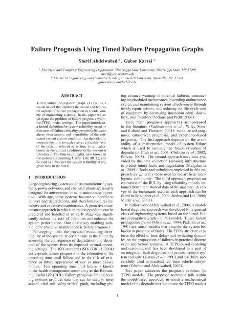
Figure 1: A TFPG model (t =10, Mode = A for t ∈<br />
[0, 10])<br />
In the above model, the map ET associates each edge<br />
e ∈ E with the minimum and maximum time for the<br />
failure to propagate along the edge. For an edge e ∈ E,<br />
we will use the notation e.tmin and e.tmax to indicate<br />
the corresponding minimum and maximum time<br />
for failure propagation along e, respectively. That is,<br />
given that a propagation edge is enabled (active), it will<br />
take at least (at most) tmin (tmax) time for the fault<br />
to propagate from the source node to the destination<br />
node. The map EM associates each edge e ∈ E with<br />
a subset of the system modes at which the failure can<br />
propagate along the edge. Consequently, the propagation<br />
link e is enabled (active) in a mode m ∈ M<br />
if and only if m ∈ EM(e). The map DC defines the<br />
type of a given discrepancy as either AND or OR. An<br />
OR type discrepancy node will be activated when the<br />
failure propagates to the node from any of its parents.<br />
On the other hand, an AND discrepancy node can only<br />
be activated if the failure propagates to the node from<br />
all its parents. We assume that TFPG models do not<br />
contain self loops and that failure modes are always<br />
root nodes, i.e., they cannot be a destination of any<br />
edge. Also, a discrepancy cannot be a root node, that<br />
is, every discrepancy must be a successor of another<br />
discrepancy or a failure mode.<br />
Figure 1 shows a graphical depiction of a failure<br />
propagation graph model. Rectangles in the graph<br />
model represent the failure modes while circles and<br />
squares represent OR and AND type discrepancies, respectively.<br />
The arrows between the nodes represent<br />
failure propagation. <strong>Propagation</strong> edges are parameterized<br />
with the corresponding interval, [e.tmin,e.tmax],<br />
and the set of modes at which the edge is active.<br />
Figure 1 also shows a sequence of active discrepancies<br />
(alarm signals) identified by shaded discrepancies.<br />
The time at which the alarm is observed is shown<br />
above the corresponding discrepancy. Dashed lines are<br />
used to distinguish inactive propagation links.<br />
The TFPG model captures observable failure propagations<br />
between discrepancies in dynamic systems. In<br />
this model, alarms capture state deviations from nom-<br />
D11<br />
2
Annual Conference of the Prognostics and Health Management <strong>Society</strong>, 2009<br />
inal values. The set of all observed deviations corresponds<br />
to the monitored discrepancy set in the TFPG<br />
model. <strong>Propagation</strong> edges, on the other hand, correspond<br />
to causality (for example, as defined by energy<br />
flow) in the system dynamics. Due to the dynamic nature<br />
of the system, failure effects take time to propagate<br />
between the system components. Such time in<br />
general depends on the systems time constants as well<br />
as the size and timing of underlying failure. <strong>Propagation</strong><br />
delay intervals can be computed analytically or<br />
through simulation of an accurate physical model.<br />
<strong>Failure</strong> propagation in a TFPG system has simple<br />
semantics. The state of a node indicates whether the<br />
failure effects reached this node. For an OR type node<br />
v ′ and an edge e =(v, v ′ ) ∈ E, once a failure effect<br />
reaches v at time t it will reach v ′ at a time t ′ where<br />
e.tmin ≤ t ′ − t ≤ e.tmax. On the other hand, the<br />
activation period of an AND alarm v ′ is the composition<br />
of the activation periods for each link (v, v ′ ) ∈ E.<br />
For a failure to propagate through an edge e =(v, v ′ ),<br />
the edge should be active throughout the propagation,<br />
that is, from the time the failure reaches v to the time<br />
it reaches v ′ . An edge e is active if and only if the current<br />
operation mode of the system, m c is in the set of<br />
activation modes of the edge, that is, m c ∈ EM(e).<br />
When a failure propagates to a monitored node v ′<br />
(DS(v ′ )=A) its physical state is considered ON, otherwise<br />
it is OFF. If the link is deactivated any time<br />
during the propagation (because of mode switching),<br />
the propagation stops. Links are assumed memoryless<br />
with respect to failure propagation so that current<br />
failure propagation is independent of any (incomplete)<br />
previous propagation. Also, once a failure effect<br />
reaches a discrepancy its state will change permanently<br />
and will not be affected by any future failure<br />
propagation.<br />
3 THE CONSISTENCY-BASED REASONING<br />
APPROACH<br />
The reasoning algorithm for TFPG model diagnosis<br />
is based on a consistency relationship defined using<br />
three state mappings for the graph nodes of the TFPG<br />
model: physical, observed, and hypothetical.<br />
A physical system state corresponds to the current<br />
state of all nodes in the TFPG model. At any time<br />
t the physical state is given by a map AS t : V →<br />
{ON, OFF}×R, where V is the set of nodes in the TFPG<br />
model. An ON state for a node indicates that the failure<br />
(effect) reached this node, otherwise it is set to OFF.<br />
The physical state at time t is denoted AS t (v).state,<br />
while AS t (v).time denote the last time at which the<br />
state of v is changed. <strong>Failure</strong> effects are assumed permanent,<br />
therefore, the state of a node once changed<br />
will remain constant after that. A similar map is used<br />
to define the state of edges based on the current mode<br />
of the system.<br />
The observed state at time t is defined as a map<br />
S t : D →{ON, OFF} ×R. Clearly, observed states<br />
are only defined for discrepancies. The observed state<br />
of the system may not be consistent with the failure<br />
propagation graph model temporal constraints, due to<br />
potential failures in the alarm monitors. However, we<br />
assume that monitored discrepancy indicators are permanent<br />
so that once the observed state of a discrepancy<br />
is changed, it will remain constant after that.<br />
The aim of the diagnosis reasoning process is to find<br />
a consistent and plausible explanation of the current<br />
system state based on the observed state. Such explanation<br />
is given in the form of a valid hypothetical<br />
state. A hypothetical state is a map that defines node<br />
states and the interval at which the node changes its<br />
state. Formally a hypothetical state at time t is a map<br />
H V ′<br />
t : V ′ → {ON, OFF} ×R × R where V ′ ⊆ V .<br />
Similar to actual states, hypothetical states are defined<br />
for both discrepancies and failure modes. The estimated<br />
earliest (latest) time of state change is denoted<br />
H(v).terl (H(v).tlat).<br />
A hypothetical state is an estimation of the current<br />
state of all nodes in the system and the time period at<br />
which each node changed its states. An estimation of<br />
the current state is valid only if it is consistent with the<br />
TFPG model. State consistency in TFPG models is<br />
a node-parents relationship that can be extended pairwise<br />
to arbitrary subsets of nodes. Formally, let Pr(v)<br />
denotes the set of parents of v in a TFPG model G. We<br />
can define observable consistency at time t as a relation<br />
OCons t ⊂P(V ) × V such that (V ′ ,v) ∈ OCons<br />
if and only if V ′ =Pr(v) and the observable state of v<br />
is consistent with that of all its parents V ′ based on the<br />
map S t and the failure propagation semantics. The observable<br />
state consistency relationship can be directly<br />
extended to any set of nodes representing a subgraph<br />
of G. In this case we overload the relationship OCons<br />
so that OCons t ⊆P(V ), where for each V ′ ⊆ V :<br />
V ′ ∈ OCons t ⇔ ∀v ∈ V ′ (Pr V ′(v),v) ∈ OCons<br />
where Pr V ′(v) is the set of parents of v restricted to<br />
V ′ . The set of maximally consistent set of nodes is<br />
denoted by Φ t where V ′ ∈ Φ t if and only if<br />
V ′ ∈ OCons t and (∀V ′′ ⊆ V ) V ′ ⊂ V ′′ ⇒<br />
V ′′ ∕∈ OCons t<br />
The set Φ t can be efficiently computed incrementally<br />
based on Φ t−1 based on a new event e t . The<br />
event e t corresponds to either a new triggered monitored<br />
discrepancy or a time-out event generated when<br />
a sensor alarm is not observed with state ON while<br />
it is supposed to be based on its current hypothetical<br />
state. The underlying procedure will be denoted<br />
UpdateMCO(Φ t−1 ,e t ). Note that initially Φ 0 =<br />
{V }.<br />
Based on the semantics of failure propagation it is<br />
possible to define a constructive notion of hypothetical<br />
consistency such that given a consistent hypothetical<br />
state H V ′<br />
t it is possible to extend this map forward<br />
(procedure BProp(H V ′<br />
t ,v))by assigning the maximal<br />
3
Annual Conference of the Prognostics and Health Management <strong>Society</strong>, 2009<br />
hypothetical state of the node v based on the hypothetical<br />
state of its parents in V ′ , or backward (operation<br />
FProp(H V ′<br />
t ,v)) by assigning the maximal hypothetical<br />
state for v ′ based on the state of its children in V ′ .<br />
The following algorithm outlines the incremental reasoning<br />
procedure.<br />
Algorithm 1 The diagnosis procedure Diag(Φ t−1 ,e t )<br />
Φ t ← UpdateMCO(Φ t−1 ,e t )<br />
HS t ← ∅<br />
define<br />
In(X) :={v ∈ X∣(∀v ′ ∈ X) (v, v ′ ) ∕∈ E}<br />
PSet(X) :={v ∈ V − X∣(∃v ′ ∈ In(X)) (v, v ′ ) ∈<br />
E}<br />
ODC(X) :=∪ v∈X Reach(v) − X<br />
TSet(X) :={v ∈ V − X∣ODC(X) × v ∩ E = ∅}<br />
CSet(X) :={v ∈ TSet(X)∣(∃v ′ ∈ X) (v ′ ,v) ∈<br />
E}<br />
end define<br />
for all V ′ ∈ Φ t do<br />
H ← S t ∣ V ′<br />
while PSet(V ′ ) ∕= ∅ do<br />
select v from PSet(V ′ )<br />
H ← BProp(H, v)<br />
V ′ ← V ′ ∪{v}<br />
end while<br />
while CSet(V ′ ) ∕= ∅ do<br />
select v from CSet(V ′ )<br />
H ← FProp(H, v)<br />
V ′ ← V ′ ∪{v}<br />
end while<br />
for all v ∈ V − V ′ do<br />
H(v).state ← OFF<br />
H(v).terl,H(v).terl ← 0<br />
end for<br />
HS t ← HS t ∪{H}<br />
end for<br />
return Φ t ,HS t<br />
In the above algorithm, for a given subset, X, of<br />
the TFPG nodes, In(X) is the set of all nodes in X<br />
that do not have children in X. These nodes forms<br />
the interior boundary for X. PSet(X) is the set of all<br />
nodes outside X that are connected (as children to the<br />
interior boundary of X, In(X). ODC(X) is the set<br />
of nodes outside X that is reachable from nodes inside<br />
X (Reach(v) is the set of nodes reachable from<br />
v). TSet(X) is the set of terminal nodes (those without<br />
children in the TFPG model) outside of X that are<br />
reachable from X. CSet(X) is the set of terminal<br />
nodes outside of X that are directly connected (as a<br />
child) to a node from X.<br />
The above diagnosis algorithm returns a set of new<br />
hypotheses that can consistently explain the current<br />
observed state of the TFPG system. A failure report<br />
is then generated from the computed set of hypotheses<br />
HS t . The failure report enlists the set of all consistent<br />
state assignments that maximally matches the current<br />
set of observations. Any observed state that does not<br />
match the current hypothesis is considered faulty. A<br />
detailed description and analysis of the diagnosis algorithm<br />
can be found in (Abdelwahed et al., 2005).<br />
3.1 Hypotheses Ranking<br />
The quality of the generated hypotheses is measured<br />
based on three independent factors:<br />
∙ Plausibility is a measure of degree to which a<br />
given hypothesis group explains the current fault<br />
signature. Plausibility is typically used as the first<br />
metric for sorting the hypotheses, focusing the<br />
search on the failure modes that explain the data<br />
that is currently being observed.<br />
∙ Robustness is a measure of the degree to which a<br />
given hypothesis is expected to remain constant.<br />
Robustness is typically used as the second metric<br />
for sorting the hypotheses, helping to determine<br />
when to take action to repair the system.<br />
∙ <strong>Failure</strong> Rate is a measure of how often a particular<br />
failure mode has occurred in the past.<br />
The plausibility metric considers two independent<br />
factors, namely, alarm consistency and failure mode<br />
parsimony. The alarm consistency factor is defined as<br />
the ratio of the active consistent alarms to that of all<br />
(currently) identified alarms. The failure mode factor<br />
is defined as the ratio of identified failure modes (according<br />
to the underlying hypothesis) to the total number<br />
of failure modes in the system. This factor is a<br />
direct representation of the parsimony principle (a hypothesis<br />
with the least number of failed components is<br />
more plausible). Hypotheses plausibility metrics are<br />
ordered, with the alarm consistency factor being the<br />
most dominant.<br />
The diagnoser selects the current set of hypothesis<br />
incrementally in an attempt to improve the current<br />
plausibility measure. In other words, the diagnoser<br />
will update a given hypothetical state map only if such<br />
update can increase the plausibility of the underlying<br />
hypothesis. In addition, changes are restricted so that<br />
the updated hypothesis remains valid.<br />
4 ASPECTS OF FAILURE PROGNOSIS IN<br />
TFPG MODELS<br />
In general, the aim of failure prognosis is to estimate<br />
the system reliability, given a set of conditions and observations,<br />
by assessing how close the system is to a<br />
critical manifestation of current failures. The reliability<br />
estimation can then be used to reconfigure the system,<br />
change the operating settings, or schedule specific<br />
maintenance procedures targeting the faulty components.<br />
In the TFPG modeling and reasoning settings,<br />
the prognosis problem and the associated reliability<br />
measure can be defined based on three main factors,<br />
namely failure criticality levels, diagnosis or hypothesis<br />
plausibility, and the time distance from the current<br />
state to the critical failure.<br />
4
Annual Conference of the Prognostics and Health Management <strong>Society</strong>, 2009<br />
Current state: defined by<br />
observed alarms as<br />
supported by a consistent<br />
hypothesis<br />
Plausibility<br />
front (variable)<br />
Criticality front<br />
(fixed)<br />
Critical section: a set of<br />
monitored discrepancies<br />
corresponding to a known<br />
critical faulty condition<br />
FM1<br />
FM2<br />
…<br />
FM3<br />
Plausibility level<br />
Defined by all the alarms<br />
supporting a set of<br />
hypothesis with the same<br />
plausibility<br />
Proximity<br />
Defined by the time<br />
required to reach from the<br />
current state to future<br />
critical states.<br />
Criticality level<br />
Corresponds to a set of<br />
monitored alarms with a<br />
given criticality value w.r.t.<br />
failure propagation<br />
Figure 2: The main factors affecting the evaluation of the system reliability for TFPG models.<br />
The first factor addresses the fact that different sections<br />
of the system may correspond to different levels<br />
of criticality with respect to system operation. These<br />
sections can be identified using a measure of criticality<br />
level for all discrepancies in the systems. The second<br />
factor address the current estimated (diagnosed) condition<br />
of the system and the plausibility of the corresponding<br />
hypothesis. The third factor, is the timing<br />
proximity of the current estimated state relative to a<br />
given critical region of the system. All these factor<br />
directly contribute to the reliability of the system at a<br />
given time. These three factors as illustrated in Figure<br />
2. We will discuss these factors in details in the<br />
reminder of this section.<br />
4.1 <strong>Failure</strong> Criticality<br />
In typical practical situations, failure progresses starting<br />
from the initial failure modes into several stages<br />
with increasing level of criticality. To capture this situation,<br />
we define the map CL : D → N that assign to<br />
each discrepancy, d ∈ D, a criticality level CL(d). The<br />
lowest criticality level, 0, is reserved for non-critical<br />
discrepancies and all failure modes. To capture the increasing<br />
criticality with respect to propagation depth,<br />
we assume that<br />
(∀d ′ ,d∈ D) (d ′ ,d) ∈ E −→ CL(d ′ ) ≤ CL(d)<br />
The above condition states that if d ′ is a parent of<br />
d in a TFPG model then the criticality level of d ′<br />
should be less than of equal to that of d. As a consequence,<br />
the criticality levels along any given path<br />
in a TFPG model form a monotonically increasing sequence.<br />
Note that we only assign a criticality level to<br />
all monitored and non-monitored discrepancies D and<br />
assign failure modes the default 0.<br />
Based on the definition of criticality levels, we can<br />
define criticality fronts associated with a given TFPG<br />
model by the map, CF : N →P(D), as follows.<br />
(∀d ∈ D) d ∈ CF(n) ←→ CL(d) ≥ n and<br />
(∀(d ′ ,d) ∈ E) CL(d ′ ) ≤ n<br />
The set of criticality fronts are essentially the<br />
codomain of the above map, and the set of criticality<br />
front levels CFL are the set {n ∈ N ∣ CF(n) ∕= ∅}.<br />
It can be shown that CFL corresponds bijectively to<br />
the codomain of CL. Based on the above definitions,<br />
a criticality front level, n ∈ N, corresponds to a graph<br />
cut of the TFPG model in which the nodes on one side<br />
of the cut have criticality levels less than n and the<br />
remaining nodes have criticality level greater than or<br />
equal to n. Figure 3 shows an example TFPG model<br />
with assigned criticality levels and the corresponding<br />
criticality fronts.<br />
Criticality levels are typically assessed based on the<br />
requirements for system operation and functionality.<br />
In particular, the criticality value for a given discrepancy<br />
depends on the operation cost associated with the<br />
5
Annual Conference of the Prognostics and Health Management <strong>Society</strong>, 2009<br />
CFL=1 CFL=2 CFL=3 CFL=4 CFL=5<br />
FM1<br />
CL=0<br />
D1<br />
CL=0<br />
D4<br />
CL=2<br />
FM2<br />
CL=0<br />
D2<br />
D5<br />
CL=3<br />
D8<br />
CL=5<br />
CL=1<br />
D6<br />
FM3<br />
CL=4<br />
CL=0<br />
D3<br />
CL=2<br />
D7<br />
CL=4<br />
FM4<br />
CL=0<br />
Figure 3: A TFPG model with assigned criticality levels and the corresponding criticality fronts.<br />
fault reaching and progressing from the discrepancy.<br />
This will include the cost of maintenance, reconfiguration,<br />
and recovery when applicable. However, in some<br />
situations, it is not possible to have a precise value for<br />
the criticality of a sensor. In such situations, an enumeration<br />
of criticality levels (ex. low, medium, and<br />
high) can be used to distinguish between sensors with<br />
respect to fault severity. Such enumeration can be assigned<br />
an approximate integer value, that reflects its<br />
relative importance, which can be used later to compute<br />
a reliability measure for the system, in terms of<br />
the remaining useful life (RUL) or the time to criticality,<br />
as discussed later in this paper.<br />
4.2 State Estimation Plausibility<br />
As discussed in the previous section, the TFPG reasoning<br />
algorithms relies on sensor signals (alarms) and<br />
the TFPG model structure to identify the most plausible<br />
estimates of the current system condition as a set of<br />
state hypotheses. The plausibility of each hypothesis is<br />
defined based on the number of supporting sensor signals<br />
(alarms) versus the inconsistent and missing ones.<br />
We will write A(H) for the set of discrepancies (monitored<br />
or not) that are presumed active (ON) according<br />
to the H and I(H) for the set of discrepancies (monitored<br />
or not) that are presumed inactive (OFF) according<br />
to H. That is,<br />
A(H) ={d ∈ D ∣ H(d).state = OFF<br />
The state front of a hypothesis H is denoted SF H and<br />
is defined as a set of discrepancies D ′ ⊆ D such that<br />
(∀d ∈ SF H )<br />
d ∈ A(H) and (∃(d, d ′ ) ∈ E) d ′ ∈ I(H)<br />
That is, the state front SF H is the set of discrepancies<br />
that are currently active as estimated by H but some<br />
of their children discrepancies are not active according<br />
to H. Given that any discrepancy in D can either be<br />
in A(H) or I(A) but not both. The set SF H is welldefined<br />
and the boundary line between D ′ and D − D ′<br />
forms a graph cut for the underlying TFPG model.<br />
The intuitive meaning of the state front for a hypothesis,<br />
is that all the discrepancies on this front are have<br />
the same likelihood of being active at the current time<br />
and they are forming the front of fault propagation in<br />
the sense that they are the discrepancies that could become<br />
active based on the next set of alarms as the fault<br />
propagation continues to progress.<br />
The plausibility of a state front is equal to the plausibility<br />
of the underlying hypothesis. As it is possible<br />
that several hypotheses can have the same plausibility<br />
level, several state front may have the same plausibility<br />
level.<br />
4.3 Time Proximity<br />
The time proximity factor measures how close the current<br />
state of the system is to a future failure. As discussed<br />
earlier, future failures are identified by their<br />
criticality level front as defined by the map CF. Each<br />
front is defined as a set of discrepancies at the boundary<br />
of a graph cut for the TFPG model. Similarly, the<br />
current state is defined by a set of hypotheses with<br />
a given plausibility level and is identified by the discrepancies<br />
at the boundaries of the cut formed by the<br />
underlying hypothesis level state front. Accordingly,<br />
the time proximity factor is a measure for the temporal<br />
6
Annual Conference of the Prognostics and Health Management <strong>Society</strong>, 2009<br />
distance between two fronts (graph cuts) each corresponding<br />
to a set of discrepancies in the TFPG model.<br />
To define such distance, consider two sets of discrepancies<br />
D 1 ,D 2 ⊆ D. Assuming that all discrepancies<br />
in D 1 are either ancestors of some discrepancies<br />
in D 2 or not connected to any discrepancy in D 2 ,we<br />
define the propagation time between D 1 and D 2 with<br />
respect to a hypothesis H, denoted t H (D 1 ,D 2 ) as the<br />
minimum time to trigger discrepancy in D 2 as a result<br />
of a set of failure propagation from discrepancies<br />
in D 1 . We write D 1 ≺ D 2 if the above condition is<br />
satisfied.<br />
To compute ˆt H (D 1 ,D 2 ), we consider the set of all<br />
discrepancies that are children of D 1 . We computer the<br />
earlier propagation time to these discrepancies based<br />
on the activation times of their parent nodes according<br />
to H. The computation of the earliest propagation<br />
time for all subsequent nodes continues as the earlier<br />
propagation times becomes available for their parents.<br />
The computation will continue until the earlier propagation<br />
time is computed for all the nodes in D 2 . The<br />
minimum time is selected as the output. Algorithm 2<br />
outlines the computation procedure.<br />
Algorithm 2 The propagation time procedure<br />
ˆt H (D 1 ,D 2 )<br />
assumption: D 1 ≺ D 2<br />
if D 1 ∩ D 2 ∕= ∅ then<br />
return 0<br />
end if<br />
define RSet(X) := {d ∈ D − X∣(∀d ′ ∈<br />
D) (d ′ ,d) ∈ E → d ′ ∈ X}<br />
TNodes = {(d, H(d).terl) ∣ d ∈ A(H)}<br />
t min = ∞<br />
while D 2 ∕⊂ TNodes.nodes do<br />
select d from RSet(D 1 )<br />
compute terl(TNodes,d)<br />
if d ∈ D 2 then<br />
t min = min(t min , terl(d))<br />
end if<br />
end while<br />
return t min<br />
In algorithm 2, for a given subset of nodes X in the<br />
TFPG model, RSet(X) is the set of discrepancies outside<br />
of X where all their parents belongs to X. The<br />
function terl(TNodes,d) computes the earliest time<br />
for d to be activated based on the earlier time the parents<br />
of d are activated. This function can be directly<br />
computed based on the semantics of failure propagation<br />
in TFPG models.<br />
4.4 Time to Criticality<br />
Given a set of criticality levels, the associated criticality<br />
fronts can be computed directly from the earlier<br />
definition. The state front for a given hypothesis can<br />
be directly computed based on the given definition. Let<br />
Y be the set of hypothesis with the highest plausibility<br />
value at a time t. We define the time to criticality level<br />
n at a give time t, denoted TTC(Y,n), as follows<br />
TTC(Y,n)=min{ˆt H (SF H , CF(n)) ∣ H ∈ Y }<br />
That is, the time to criticality level n is the minimum of<br />
all propagation times for all hypotheses with the maximum<br />
plausibility. In practice, there are typically few<br />
enumerated criticality levels. The time to criticality,<br />
therefore, follows the increasing order of the criticality.<br />
That is, the time to reach a high criticality level is<br />
usually longer than the time to reach a lower criticality<br />
level, as expected. However, this is not always the case<br />
as shown the in Figure 4. In this example, there are<br />
three different paths from the state (estimation) front<br />
SF H to the criticality front level 1 (CFL=1), where<br />
H is the most plausible hypothesis in which D2, D3,<br />
D4 are assumed active and D1 is assumed faulty. In<br />
this example, the time to criticality to the first level is<br />
3 (time units) while the time to criticality for the next<br />
higher level is 1.<br />
5 CONCLUSION<br />
In this paper we addressed a model-based prognosis<br />
problem in the TFPG settings. We presented the three<br />
main factors that directly affect the system reliability<br />
at a given state, namely, criticality levels, current state<br />
front, and time proximity. Based on the formal definitions<br />
of these factors, we introduced an algorithm to<br />
compute the time to reach a given critical level based<br />
on the current conditions of the system. The time to<br />
criticality can be used as a measure for system reliability.<br />
In future work we will consider a more general concept<br />
of system reliability that integrate different criticality<br />
levels as well as states with different plausibility<br />
values. We will also investigate the reliability assessment<br />
for systems in which propagation times are<br />
not provided. In another research direction we will investigate<br />
the problem of sensor assignment to achieve<br />
certain minimum time to criticality levels at specific<br />
system conditions.<br />
ACKNOWLEDGMENTS<br />
The authors would like to thank Timothy J. Wilmering<br />
and Stanley Ofsthun for their helpful comments<br />
and discussions regarding the problem of diagnosis for<br />
TFPG models. This work is funded, in part, by Boeing.<br />
REFERENCES<br />
(Abdelwahed et al., 2004) S. Abdelwahed, G. Karsai,<br />
and G. Biswas. System diagnosis using hybrid failure<br />
propagation graphs. In The 15th International<br />
Workshop on Principles of Diagnosis, Carcassonne,<br />
France, 2004.<br />
(Abdelwahed et al., 2005) S. Abdelwahed, G. Karsai,<br />
and G. Biswas. A consistency-based robust diagnosis<br />
approach for temporal causal systems. In The<br />
7
Annual Conference of the Prognostics and Health Management <strong>Society</strong>, 2009<br />
State front<br />
CFL=1<br />
CFL=2<br />
FM1<br />
D1<br />
D2<br />
3,6<br />
D6<br />
4,7<br />
D8<br />
FM2<br />
D3<br />
1,2<br />
D5<br />
4,5<br />
D9<br />
FM3<br />
D4<br />
3,8<br />
D7<br />
2,5<br />
1, 8<br />
3, 9<br />
D10<br />
Figure 4: Time to criticality example<br />
16th International Workshop on Principles of Diagnosis,<br />
Pacific Grove, CA, 2005.<br />
(Chelidze et al., 2002) D. Chelidze, J.P. Cusumano,<br />
and A. Charterjee. A dynamical systems approach<br />
to damage evolution tracking, part 1: The experimental<br />
method. Journal of Vibration and Acoustics,<br />
124:250–257, 2002.<br />
(ISO-13381-1, 2004) ISO-13381-1. Condition monitoring<br />
and diagnostics of machines - prognostics -<br />
part1: General guidelines. Int. Standard, 2004.<br />
(Jardine and Lin, 2006) A. K. S. Jardine and D. Lin.<br />
A review on machinery diagnostics and prognostics<br />
implementing condition-based maintenance.<br />
Mechanical Systems and Signal Processing,<br />
20(7):1483–1510, 2006.<br />
(Karsai et al., 2003) G. Karsai, G. Biswas, and S. Abdelwahed.<br />
Towards fault-adaptive control of complex<br />
dynamic systems. In T. Samad and G. Balas,<br />
editors, Software-Enabled Control: Information<br />
Technology for Dynamical Systems, chapter 17.<br />
IEEE publication, 2003.<br />
(Lebold and Thurston, 2001) M. Lebold and<br />
M. Thurston. Open standards for conditionbased<br />
maintenance and prognostic systems. In 5th<br />
annual maintenance and reliability conference,<br />
Gatlinburg, USA., 2001.<br />
(Luo et al., 2003) J. Luo, M. Namburu, K. Pattipati,<br />
L. Qiao, M. Kawamoto, and S. Chigusa. Modelbased<br />
prognostic techniques. In Proc. of IEEE AU-<br />
TOTESTCON, pages 330–340, 2003.<br />
(Medjaher et al., 2009) K. Medjaher, J.-Y. Moya, and<br />
N. Zerhouni. <strong>Failure</strong> prognostic by using dynamic<br />
bayesian networks. In 2nd IFAC Workshop on Dependable<br />
Control of Discrete Systems, DCDS’09,<br />
Bari, Italy, 2009.<br />
(Misra et al., 1994) A. Misra, J. Sztipanovits, and<br />
J. Carnes. Robust diagnostics: Structural redundancy<br />
approach. In SPIE’s Symposium on Intelligent<br />
Systems, 1994.<br />
(Muller et al., 2008) A. Muller, M.C. Suhner, and<br />
B. Iung. Formalisation of a new prognosis model<br />
for supporting proactive maintenance implementation<br />
on industrial system. Reliability Engineering<br />
and System Safety, 93:234–253, 2008.<br />
(Ofsthun and Abdelwahed, 2007) S. Ofsthun and<br />
S. Abdelwahed. Practical applications of timed<br />
failure propagation graphs for vehicle diagnosis. In<br />
IEEE Systems Readiness Technology Conference,<br />
Autotestcon’07, pages 250–259, Baltimore, MD,<br />
September 2007.<br />
(Padalkar et al., 1991) S. Padalkar, J. Sztipanovits,<br />
G. Karsai, N. Miyasaka, and K. C. Okuda. Realtime<br />
fault diagnostics. IEEE Expert, 6(3):75–85,<br />
1991.<br />
(Provan, 2003) G. Provan. <strong>Prognosis</strong> and conditionbased<br />
monitoring: an open systems architecture. In<br />
5th IFAC Symposium on Fault Detection, Supervision<br />
and Safety of Technical Processes, 2003.<br />
(Vachtsevanos et al., Wiley Sons) G. Vachtsevanos,<br />
F. L. Lewis, M. Roemer, A. Hess, and B. Wu.<br />
Intelligent Fault Diagnosis and <strong>Prognosis</strong> for<br />
Engineering Systems, volume 2006. Intelligent<br />
Fault Diagnosis and <strong>Prognosis</strong> for Engineering<br />
Systems., New Jersey, Hoboken, Wiley & Sons.<br />
8
Annual Conference of the Prognostics and Health Management <strong>Society</strong>, 2009<br />
(Vichare and Pecht, 2006) N. Vichare and M. Pecht.<br />
Prognostics and health management of electronics.<br />
IEEE Transactions on Components and Packaging<br />
Technologies, 29(1):222–229, 2006.<br />
Sherif Abdelwahed is an Assistant Professor with<br />
Electrical and Computer Engineering Department at<br />
Mississippi State University. He received his Ph.D.<br />
degree in Electrical and Computer Engineering from<br />
the University of Toronto, Canada, in 2002. From<br />
2000 to 2001, he was a research scientist with the<br />
system diagnosis group at the Rockwell Scientific<br />
Company. From 2002 to 2007 he worked as a research<br />
assistant professor with the Institute for Software<br />
Integrated Systems at Vanderbilt University. He<br />
conducts research on model-based design and analysis<br />
of self-managing computation systems. His research<br />
interests also include modeling and analysis of<br />
distributed real-time systems, automated verification,<br />
model-based fault diagnosis and prognosis techniques,<br />
and model-integrated computing. He has published<br />
over 75 publications. He is a senior member of the<br />
IEEE and member of Sigma Xi.<br />
Gabor Karsai is a Professor of Electrical Engineering<br />
and Computer Science at Vanderbilt University,<br />
and Senior Research Scientist at the Institute for<br />
Software-Integrated Systems. He has over twenty-five<br />
years of experience in software engineering. He conducts<br />
research in the design and implementation of<br />
embedded systems, in programming tools for visual<br />
programming environments, in the theory and practice<br />
of model-integrated computing. He received his<br />
BSc, MSc, and Dr. Techn. degrees from the Technical<br />
University of Budapest, in 1982, 1984 and 1988,<br />
respectively, and his PhD from Vanderbilt University<br />
in 1988. He has published over 100 papers, and he is<br />
the co-author of four patents. He has worked on several<br />
large projects in the recent past, including one on<br />
fault-adaptive control technology that has been transitioned<br />
into aerospace applications, and another one<br />
on the model-based integration of embedded systems<br />
whose resulting tools are being used in embedded software<br />
development tool chains worldwide.<br />
9