
Create successful ePaper yourself
Turn your PDF publications into a flip-book with our unique Google optimized e-Paper software.
<strong>Experiment</strong> <strong>22</strong><br />
<strong>The</strong> <strong>Current</strong> <strong>Balance</strong><br />
Advance Reading:<br />
(Halliday, Resnick and Walker)<br />
Chapter 28, sections 28-1<br />
through 28 -3<br />
Equipment:<br />
1 Pasco <strong>Current</strong> <strong>Balance</strong><br />
apparatus<br />
1 Dial-o-gram balance<br />
1 power supply<br />
3 double-banana plug wires.<br />
1 Kelvin DMM<br />
1 table clamp<br />
1 short rod<br />
Objective:<br />
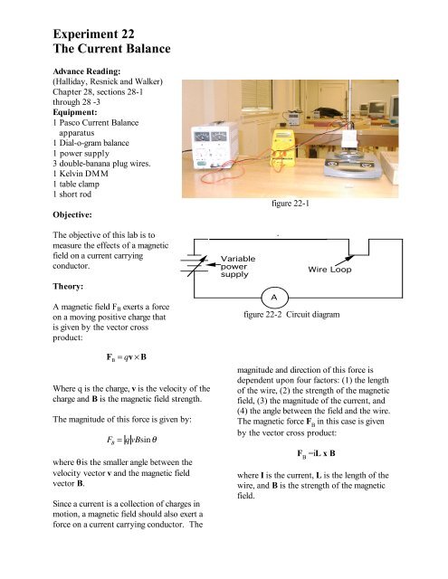
<strong>The</strong> objective of this lab is to<br />
measure the effects of a magnetic<br />
field on a current carrying<br />
conductor.<br />
<strong>The</strong>ory:<br />
A magnetic field F B exerts a force<br />
on a moving positive charge that<br />
is given by the vector cross<br />
product:<br />
F B<br />
= qv ! B<br />
Where q is the charge, v is the velocity of the<br />
charge and B is the magnetic field strength.<br />
<strong>The</strong> magnitude of this force is given by:<br />
F B<br />
= q vBsin!<br />
where θ is the smaller angle between the<br />
velocity vector v and the magnetic field<br />
vector B.<br />
Since a current is a collection of charges in<br />
motion, a magnetic field should also exert a<br />
force on a current carrying conductor. <strong>The</strong><br />
figure <strong>22</strong>-1<br />
<strong>Current</strong> Limiting Resistor<br />
Variable<br />
power<br />
supply<br />
A<br />
Wire Loop<br />
figure <strong>22</strong>-2 Circuit diagram<br />
magnitude and direction of this force is<br />
dependent upon four factors: (1) the length<br />
of the wire, (2) the strength of the magnetic<br />
field, (3) the magnitude of the current, and<br />
(4) the angle between the field and the wire.<br />
<strong>The</strong> magnetic force F B<br />
in this case is given<br />
by the vector cross product:<br />
F B<br />
=iL x B<br />
where I is the current, L is the length of the<br />
wire, and B is the strength of the magnetic<br />
field.
Procedure:<br />
Part 1: Force vs. <strong>Current</strong><br />
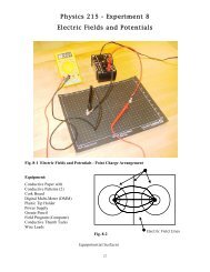
1. Set-up the apparatus as it appears in<br />
figure 21-1 and figure 21-2 using the current<br />
loop numbered SF 42. <strong>The</strong> circuit consists<br />
of a power supply, an ammeter (DMM) and<br />
the wire loop all connected in series.<br />
Before placing the magnet on the digital<br />
balance, the balance should be zeroed. Push<br />
the “zero” button once.<br />
2. Place the long magnet on the center of the<br />
balance pan. <strong>The</strong> wire loop should be<br />
arranged so that it passes through the pole<br />
region of the magnet (i.e., the horizontal part<br />
of the wire is just below the top of the<br />
magnet). See Figure 21-3 below<br />
After it has been approved, plug in the<br />
power supply and adjust the dial until the<br />
DMM reads approximately 1.0 amps. .<br />
When the current is turned on, the magnet<br />
should be deflected downwards. Read the<br />
new mass from the balance and calculate the<br />
weight F in newtons. It should be greater<br />
than it was when no current is flowing. If<br />
the balance reads less than before,<br />
reverse the wires on the arm of the<br />
current balance. <strong>The</strong> difference in the<br />
weight with the current on, and with the<br />
current off is the force due to the magnetic<br />
field, F B . ( i.e., F B =F - F 0 ) Calculate this<br />
force.<br />
5. Increase the current in 1.0 amp<br />
increments until 5.0 amps is reached.<br />
Record the current and the magnetic force for<br />
each step. Using Graphical Analysis plot<br />
magnetic force vs. current and determine the<br />
best-fit line. Be sure and include (0,0) data<br />
point. From the slope you will determine<br />
the magnetic field of your magnet.<br />
Part 2: Force vs. Length of Wire<br />
6. For this part of the lab you will need to<br />
know the effective length of the wire loops.<br />
<strong>The</strong>y are as follows:<br />
Figure <strong>22</strong>-3<br />
3. Measure the mass of the long magnet<br />
with no current flowing and calculate its<br />
weight in newtons. This is your zero force,<br />
F 0 or zero weight, W 0 .<br />
Once the experiment starts, do not move<br />
the setup. It is also important to keep all<br />
metal objects and wires away from the<br />
magnet. <strong>The</strong>se could affect the data.<br />
4. Before plugging in the power supply,<br />
have your instructor check the circuit.<br />
SF 40 1.2 cm<br />
SF 37 2.2 cm<br />
SF 39 3.2 cm<br />
SF 38 4.2 cm<br />
SF 41 6.4 cm<br />
SF 42 8.4 cm<br />
Note that the numbers on the loops do<br />
not signify the length of the wire.<br />
Insert the shortest wire segment (SF 40) into<br />
the holder. Measure the mass of the magnet<br />
holder and the magnets again and determine<br />
its weight. (It should be about the same as<br />
before).
7. Adjust the power supply until the<br />
DMM reads 2.0 amps. Determine the<br />
magnetic force. Repeat for all six wire loops.<br />
Plot magnetic force vs. wire length. Be sure<br />
and include (0,0) data point. From the<br />
slope you will determine the magnetic field<br />
of your magnet.<br />
5. Calculate the field strength of the wide<br />
magnets using the slope of the graph in part<br />
one.<br />
Part 3: Force vs. Angle<br />
8. Plug the <strong>Current</strong> <strong>Balance</strong> Accessory into<br />
the arm of the current balance. Replace the<br />
long magnet assembly with the small<br />
“square” magnet. See Figure <strong>22</strong>-4. Measure<br />
the mass. This is your zero current mass.<br />
9. Set the angle to 0 o with the direction of<br />
the coil wire parallel to the magnetic field.<br />
See Figure <strong>22</strong>-5. Set the current to 2.0 amps.<br />
Re-measure the mass. If the mass changes,<br />
slightly vary the angle of the magnet setup<br />
so that the mass is as close as possible to the<br />
zero current mass. Determine the force. This<br />
force is your zero (angle) force, F 0 .<br />
10. Increase the angle in 10 o increments up<br />
to 180 o . At each angle repeat the magnetic<br />
force measurement. Plot magnetic force vs.<br />
angle. From this plot, determine the strength<br />
of the “square” magnet.<br />
Figure <strong>22</strong>-4<br />
Questions/Conclusions:<br />
1. What is the relationship between the<br />
current and the magnetic force?<br />
2. What is the relationship between the<br />
length of the wire and the magnetic force?<br />
3. What is the shape of the curve in part 3?<br />
Sketch the shape of the curve if you could<br />
rotate the current balance accessory a full<br />
360 degrees.<br />
Figure <strong>22</strong>-5<br />
4. Show F=qvBsinθ and F=iLBsinθ are<br />
dimensionally equivalent.