Optical trapping and transportation of carbon nanotubes made easy ...
Optical trapping and transportation of carbon nanotubes made easy ...
Optical trapping and transportation of carbon nanotubes made easy ...

Create successful ePaper yourself
Turn your PDF publications into a flip-book with our unique Google optimized e-Paper software.
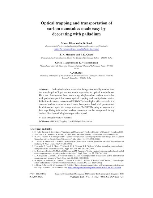
<strong>Optical</strong> <strong>trapping</strong> <strong>and</strong> <strong>transportation</strong> <strong>of</strong><br />
<strong>carbon</strong> <strong>nanotubes</strong> <strong>made</strong> <strong>easy</strong> by<br />
decorating with palladium<br />
Manas Khan <strong>and</strong> A. K. Sood<br />
Department <strong>of</strong> Physics, Indian Institute <strong>of</strong> Science, Bangalore - 560012, India<br />
Author for correspondence: asood@physics.iisc.ernet.in<br />
S. K. Mohanty <strong>and</strong> P. K. Gupta<br />
Biomedical Application Section, Centre for Advanced Technology, Indore - 452013, India<br />
Girish V. Arabale <strong>and</strong> K. Vijaymohanan<br />
Physical <strong>and</strong> Materials Chemistry Division, National Chemical Laboratory, Pune - 411008,<br />
India<br />
C.N.R. Rao<br />
Chemistry <strong>and</strong> Physics <strong>of</strong> Materials Unit, Jawaharlal Nehru Centre for Advanced Scientific<br />
Research, Bangalore - 560064, India<br />
Abstract: Individual <strong>carbon</strong> <strong>nanotubes</strong> being substantially smaller than<br />
the wavelength <strong>of</strong> light, are not much responsive to optical manipulation.<br />
Here we demonstrate how decorating single-walled <strong>carbon</strong> <strong>nanotubes</strong><br />
with palladium particles makes optical <strong>trapping</strong> <strong>and</strong> manipulation easier.<br />
Palladium decorated <strong>nanotubes</strong> (Pd/SWNTs) have higher effective dielectric<br />
constant <strong>and</strong> are trapped at much lower laser power level with greater ease.<br />
In addition, we report the <strong>transportation</strong> <strong>of</strong> Pd/SWNTs using an asymmetric<br />
line trap. Using this method <strong>carbon</strong> <strong>nanotubes</strong> can be transported in any<br />
desired direction with high <strong>transportation</strong> speed.<br />
© 2006 <strong>Optical</strong> Society <strong>of</strong> America<br />
OCIS codes: (140.7010) Trapping; (120.4610) <strong>Optical</strong> fabrication<br />
References <strong>and</strong> links<br />
1. C. N. R. Rao <strong>and</strong> A. Govindaraj, “Nanotubes <strong>and</strong> Nanowires,” The Royal Society <strong>of</strong> Chemistry (London),2005.<br />
2. S. Ghosh, A. K. Sood <strong>and</strong> N. Kumar, “Carbon Nanotube Flow Sensors,” Science 299, 1042-1044 (2003).<br />
3. H. W. C. Postma, A. Sellmeijer <strong>and</strong> C. Dekker, “Manipulation <strong>and</strong> Imaging <strong>of</strong> Individual Single-Walled Carbon<br />
Nanotubes with an Atomic Force Microscope,” Adv. Mater. 12, 1299-1302 (2000).<br />
4. T. Hertel, R. Martel <strong>and</strong> P. Avouris, “Manipulation <strong>of</strong> Individual Carbon Nanotubes <strong>and</strong> Their Interaction with<br />
Surfaces,” J. Phys. Chem. 102, 910-915 (1998).<br />
5. P. Avouris, T. Hertel, R. Martel, T. Schmidt, H. R. Shea <strong>and</strong> R. E. Walkup, “Carbon <strong>nanotubes</strong>: nanomechanics,<br />
manipulation <strong>and</strong> electronic devices,” Appl. Surf. Sci. 141, 201-209 (1999).<br />
6. L. Roschier, J. Penttila, M. Martin, P. Hakonen <strong>and</strong> M. Paalanen, “Single-electron transistor <strong>made</strong> <strong>of</strong> multiwalled<br />
<strong>carbon</strong> nanotube using scanning probe manipulation,” Appl. Phys. Lett. 75, 728-730 (1999).<br />
7. L. A. Nagahara, I. Amlani, J. Lewenstein <strong>and</strong> R. K. Tsui, “Direct placement <strong>of</strong> suspended <strong>carbon</strong> <strong>nanotubes</strong> for<br />
nanometer-scale assembly,” Appl. Phys. Lett. 80, 3826-3828 (2002).<br />
8. B. Vigolo, A. Penicaud, C. Coulon, C. Sauder, R. Pailler, C. Journet, P. Bernier <strong>and</strong> P. Poulin1, “Macroscopic<br />
Fibers <strong>and</strong> Ribbons <strong>of</strong> Oriented Carbon Nanotubes,” Science 290, 1331-1334 (2000).<br />
9. J. Plewa, E. Tanner, D. M. Mueth <strong>and</strong> D. G. Grier, “Processing <strong>carbon</strong> <strong>nanotubes</strong> with holographic optical tweezers,”<br />
Opt. Express 12, 1978-1981 (2004), http://www.opticsexpress.org/abstract.cfm?URI=OPEX-12-9-1978<br />
#9427 - $15.00 USD Received 8 November 2005; revised 22 December 2005; accepted 22 December 2005<br />
(C) 2006 OSA 9 January 2006 / Vol. 14, No. 1 / OPTICS EXPRESS 424
10. S. Tan, H. A. Lopez, C. W. Cai <strong>and</strong> Y. Zhang, “<strong>Optical</strong> Trapping <strong>of</strong> Single-Walled Carbon Nanotubes,” Nano<br />
Lett. 4, 1415-1419 (2004).<br />
11. S. K. Mohanty <strong>and</strong> P. K. Gupta, “Transport <strong>of</strong> microscopic objects using asymmetric transverse optical gradient<br />
force,” Appl. Phys. B. 81, 159-162 (2005).<br />
12. S. R. C. Vivekch<strong>and</strong>, R. Jayakanth, A. Govindaraj <strong>and</strong> C. N. R. Rao, “The Problem <strong>of</strong> Purifying Single-Walled<br />
Carbon Nanotubes,” Small 1, 920-923 (2005).<br />
13. B. C. Satishkumary, E. M. Vogl, A Govindaraj <strong>and</strong> C. N. R. Rao, “The decoration <strong>of</strong> <strong>carbon</strong> <strong>nanotubes</strong> by metal<br />
nanoparticles,” J. Phys. D: Appl. Phys. 29, 3173-3176 (1996).<br />
14. M. J. OConnell, S. M. Bachilo, C. B. Huffman, V. C. Moore, M. S. Strano, E. H. Haroz, K. L. Rialon, P. J. Boul,<br />
W. H. Noon, C. Kittrell, J. Ma, R. H. Hauge, R. B. Weisman <strong>and</strong> R. E. Smalley, “B<strong>and</strong> Gap Fluorescence from<br />
Individual Single-Walled Carbon Nanotubes,” Science 297, 593-596 (2002).<br />
15. T. Tlusty, A. Meller <strong>and</strong> R. Bar-Ziv, “<strong>Optical</strong> Gradient Forces <strong>of</strong> Strongly Localized Fields,” Phys. Rev. Lett. 81,<br />
1738-1741 (1998).<br />
1. Introduction<br />
Recent work on <strong>carbon</strong> <strong>nanotubes</strong> has revealed their potential uses in varied fields such as nanoelectronics,<br />
electron emitters in flat-panel displays, gas <strong>and</strong> liquid flow sensors, actuators etc.<br />
[1, 2]. Their mechanical, chemical, electrical <strong>and</strong> optical properties have <strong>made</strong> them a useful assembly<br />
unit for many nano-structured technological devices. It has now, therefore, become necessary<br />
to have a control over the arrangement <strong>of</strong> the <strong>nanotubes</strong> in desired patterns. Techniques<br />
such as single tube manipulation by atomic force microscopy [3, 4, 5, 6], dielectrophoresis [7],<br />
<strong>and</strong> flow-induced alignment [8] have been employed to serve the purpose. Recently, single-wall<br />
<strong>carbon</strong> <strong>nanotubes</strong> (SWNTs) were trapped using optical tweezers [9, 10] <strong>and</strong> manipulated using<br />
dynamic holographic optical tweezers [9]. Here we report how single-wall <strong>carbon</strong> <strong>nanotubes</strong><br />
decorated with Pd nanoparticles (Pd/SWNTs) can ease the optical manipulations at individual<br />
nanotube level. This is because <strong>of</strong> the increase in the effective dielectric constant <strong>of</strong> the<br />
decorated <strong>nanotubes</strong>. Furthermore, we demonstrate the <strong>transportation</strong> <strong>of</strong> Pd/SWNTs using an<br />
asymmetric optical line trap [11] that does not require the use <strong>of</strong> a scanning device [9] or micro<br />
fluid channels [10].<br />
2. Experimental details<br />
We have used SWNTs decorated with Pd metal for our experiments <strong>and</strong> compared the results<br />
with pure SWNTs. Pure SWNTs were prepared by the arc discharge method, followed by the<br />
purification process to remove the <strong>carbon</strong>aceous impurities <strong>and</strong> metal catalyst particles [12].<br />
SWNTs partially covered by Pd were prepared by dispersing 450 mg <strong>of</strong> <strong>carbon</strong> <strong>nanotubes</strong> in 25<br />
ml acetone with the aid <strong>of</strong> sonicator. 204 mg <strong>of</strong> PdCl 2 was added to the dispersion <strong>and</strong> sonicated<br />
again for 10 minutes. The sample was refluxed to 373 K for 3 hours. After solvent removal the<br />
sample was reduced in H 2 atmosphere at 773 K for 2 hours <strong>and</strong> allowed to cool. Pd/SWNTs<br />
were characterized by various techniques <strong>and</strong> the absence <strong>of</strong> unreacted PdCl 2 in the sample was<br />
confirmed. It has been shown that such treatment gives rise to <strong>nanotubes</strong> decorated with metal<br />
nanoparticles [13]. From the TGA studies, the wt% <strong>of</strong> Pd was calculated as 23%. Ellipsometry<br />
studies on the bulk samples were performed using Sentec Ellipsometer (model: SE850) to measure<br />
the enhancement in dielectric constant <strong>of</strong> SWNT after decorating with Pd nanoparticles.<br />
It was observed that there was a substantial change in the real part <strong>of</strong> the dielectric constant,<br />
Re[ε SW NT ]=1.58 to Re[ε Pd/SW NT ]=1.71 at 1064 nm. On the other h<strong>and</strong>, the imaginary part<br />
<strong>of</strong> the dielectric constant which plays an important role in heating <strong>of</strong> the sample while in the<br />
optical trap, was almost same: Im[ε SW NT ]=0.85 as compared to Im[ε Pd/SW NT ]=0.87 at 1064<br />
nm. The SWNT <strong>and</strong> Pd/SWNT samples were dispersed in 1% SDS + D 2 O solution at 20 mg/l<br />
concentration <strong>and</strong> sonicated for more than 10 hours. The SWNT <strong>and</strong> Pd/SWNT dispersions<br />
were centrifuged for 30 minutes at 16000 rpm <strong>and</strong> only the upper part <strong>of</strong> the dispersions were<br />
taken for the experiments to ensure the absence <strong>of</strong> nanotube bundles in the samples [14].<br />
#9427 - $15.00 USD Received 8 November 2005; revised 22 December 2005; accepted 22 December 2005<br />
(C) 2006 OSA 9 January 2006 / Vol. 14, No. 1 / OPTICS EXPRESS 425
A 1064nm linearly polarized laser beam from a 2.5 WNd: YVO 4 laser was focused through<br />
a 1.4 numerical aperture 100× objective to trap the <strong>nanotubes</strong>. The laser power was increased<br />
gradually to measure the threshold laser power to trap the pure SWNTs <strong>and</strong> the Pd/SWNTs.<br />
The experiments were recorded using a digital CCD camera attached to the microscope. As<br />
the size <strong>of</strong> the SWNTs are smaller than the optical microscopy resolution limit, the diffraction<br />
limited images <strong>of</strong> the trapped SWNTs are seen like a blurred dark spot at the trap center (Fig.<br />
1).<br />
For the <strong>transportation</strong> <strong>of</strong> the <strong>nanotubes</strong>, we used an asymmetric optical line trap. The nanotube<br />
dispersions used in the <strong>transportation</strong> experiments were not centrifuged <strong>and</strong> therefore the<br />
samples were not free from small nanotube bundles. Replacing a spherical lens <strong>of</strong> the telescopic<br />
pair outside the microscope by a cylindrical lens makes the laser beam focus only in one direction<br />
<strong>and</strong> hence results in a line trap in the sample plane. A schematic <strong>of</strong> the optical layout<br />
has been shown in Fig. 2. As shown in the Fig. 2, when the laser beam is tilted slightly (about<br />
Y axis), the intensity pr<strong>of</strong>ile as well as the potential well <strong>of</strong> the line trap become asymmetric<br />
[11]. Tilting the laser beam in the other direction allowed us to reverse the asymmetry while the<br />
angle <strong>of</strong> tilt governed the degree <strong>of</strong> asymmetry in the line trap. We used SWNT <strong>and</strong> Pd/SWNT<br />
dispersions for the <strong>transportation</strong> experiments at various laser power levels. The <strong>transportation</strong><br />
experiments were recorded at 25 frames per second using a CCD camera. Due to poor<br />
optical contrast <strong>and</strong> higher speed <strong>of</strong> <strong>transportation</strong>, the images <strong>of</strong> <strong>transportation</strong> <strong>of</strong> very small<br />
Pd/SWNT bundles are not clear enough. The time lapse images <strong>of</strong> <strong>transportation</strong> <strong>of</strong> a rather big<br />
bundle <strong>of</strong> Pd/SWNT have been shown in Fig. 3.<br />
Fig. 1. <strong>Optical</strong> microscope images <strong>of</strong> trapped Pd/SWNT (a-c) <strong>and</strong> pure SWNT (d). In frame<br />
(a) the laser is <strong>of</strong>f. Frame (b) shows the <strong>trapping</strong> <strong>of</strong> Pd/SWNT at 118 mW laser power. The<br />
image is a diffraction limited image <strong>and</strong> hence it does not represent the real size <strong>of</strong> the<br />
trapped nanotube. In (c), the <strong>trapping</strong> <strong>of</strong> SWNT-Pd has been shown at laser power <strong>of</strong> 170<br />
mW when more than one nanotube get trapped <strong>and</strong> a more prominent dark spot is visible<br />
at the trap center. Frame (d) shows the <strong>trapping</strong> <strong>of</strong> pure SWNT at 214 mW .<br />
3. Results<br />
Pd/SWNTs were trapped with relative ease compared to pure SWNTs. We could trap the<br />
Pd/SWNTs starting from a threshold value <strong>of</strong> the laser power <strong>of</strong> 118 mW . As shown in Fig.<br />
1, a blurred dark spot at the trap center was seen as the signature <strong>of</strong> the <strong>trapping</strong> <strong>of</strong> Pd/SWNTs.<br />
With increasing power the dark spot became more prominent as more than one nanotube were<br />
trapped. As compared to Pd/SWNTs, the threshold laser power for <strong>trapping</strong> <strong>of</strong> pure SWNTs<br />
was much higher, 214 mW , <strong>and</strong> the <strong>trapping</strong> was not as stable as that <strong>of</strong> the Pd decorated sample.<br />
Even at 214 mW , the trapped SWNTs showed greater thermal agitation <strong>and</strong> were kicked out<br />
<strong>of</strong> the optical trap in collisions with the new incoming SWNTs, whereas all trapped Pd/SWNTs<br />
stayed in the optical trap <strong>and</strong> did not show any visible thermal agitation till the laser power was<br />
decreased below the threshold value <strong>of</strong> 118 mW .<br />
Pd/SWNTs could be transported using the asymmetric optical line trap whereas this was not<br />
the case for pure SWNTs. The Pd/SWNTs were attracted to the potential well from the steeper<br />
#9427 - $15.00 USD Received 8 November 2005; revised 22 December 2005; accepted 22 December 2005<br />
(C) 2006 OSA 9 January 2006 / Vol. 14, No. 1 / OPTICS EXPRESS 426
Fig. 2. <strong>Optical</strong> layout <strong>of</strong> the asymmetric line trap. For normal incidence (beam position 1)<br />
on the cylindrical lens, a symmetric line trap is formed at the sample plane. The intensity<br />
pr<strong>of</strong>ile <strong>and</strong> the corresponding potential well for this case have been shown in inset A. When<br />
the incident beam is tilted about Y axis (position 2), the intensity pr<strong>of</strong>ile <strong>and</strong> the potential<br />
well <strong>of</strong> the line trap become asymmetric. The intensity pr<strong>of</strong>ile <strong>and</strong> the potential well corresponding<br />
to beam position 2 have been displayed in inset B. For beam position 2, the<br />
scattering force (F S2 ) gains a nonzero transverse component acting along the direction <strong>of</strong><br />
flatter potential <strong>of</strong> the line trap. TL <strong>and</strong> MO represent the tube lens <strong>and</strong> the microscope<br />
objective respectively.<br />
intensity gradient side <strong>of</strong> the line trap with very high velocity <strong>and</strong> then were pushed to the other<br />
end <strong>of</strong> the line trap with a slower velocity (Fig. 3). The absolute velocity <strong>of</strong> the <strong>transportation</strong><br />
increased with increasing laser power. For smaller bundles, the <strong>transportation</strong> speed as high as<br />
25 µm/sec was observed <strong>and</strong> bundles were transported over a length <strong>of</strong> 8 µm at laser power <strong>of</strong><br />
200 mW . The direction <strong>of</strong> <strong>transportation</strong> could be reversed just by tilting the laser beam in the<br />
opposite direction (about Y axis) (Fig. 2). The speed <strong>of</strong> <strong>transportation</strong> could also be regulated<br />
by the tilting angle <strong>of</strong> the beam. A rotation <strong>of</strong> the cylindrical lens about the optic axis (Z axis)<br />
<strong>made</strong> the line trap to rotate about the Z axis in the sample plane <strong>and</strong> using this process all the<br />
desired directions <strong>of</strong> <strong>transportation</strong> were realized.<br />
4. Discussion<br />
The difficulty in <strong>trapping</strong> <strong>of</strong> individual <strong>carbon</strong> <strong>nanotubes</strong> is tw<strong>of</strong>old, small size <strong>and</strong> low dielectric<br />
constant. In the strongly focused laser beam a nanotube gets polarized <strong>and</strong> starts interacting<br />
with the strong electric field at that point. The dipole interaction energy can be given by,<br />
∫<br />
W = −α IdV (1)<br />
where α = ε p<br />
ε 0<br />
−1 accounts for the relative difference <strong>of</strong> the dielectric constants <strong>of</strong> the nanotube<br />
(ε p ) <strong>and</strong> the surrounding medium (ε 0 ), I is the electromagnetic energy density [15] which is<br />
a sole function <strong>of</strong> the spatial coordinates for a CW lasr beam <strong>and</strong> the spatial integral is done<br />
#9427 - $15.00 USD Received 8 November 2005; revised 22 December 2005; accepted 22 December 2005<br />
(C) 2006 OSA 9 January 2006 / Vol. 14, No. 1 / OPTICS EXPRESS 427
Fig. 3. Time lapse images <strong>of</strong> the <strong>transportation</strong> <strong>of</strong> a Pd/SWNT bundle in the asymmetric<br />
line trap. The parallel lines indicate the length <strong>and</strong> direction <strong>of</strong> the line trap. A color bar in<br />
each image indicates the asymmetry in the beam intensity pr<strong>of</strong>ile <strong>of</strong> the trap. The bundle<br />
is pulled toward the maximum intensity point from the steeper gradient side with a higher<br />
velocity <strong>and</strong> then pushed to the other end at much lower speed.<br />
over the volume <strong>of</strong> the nanotube. Since both α <strong>and</strong> V are small for a individual nanotube, the<br />
value <strong>of</strong> the integral is less <strong>and</strong> as a result it does not get trapped strongly. When the <strong>nanotubes</strong><br />
are decorated with Pd nanoparticles, the effective dielectric constant <strong>and</strong> therefore α increases<br />
substantially <strong>and</strong> hence even an individual Pd/SWNT gets trapped at greater ease <strong>and</strong> at much<br />
lower laser power. In this case, the ratio α Pd/SW NT /α SW NT can be approximately calculated as<br />
2 at 1064 nm.<br />
As the Pd decorated SWNTs become more participative in optical manipulation, they get<br />
transported by the asymmetric optical line trap unlike the pure SWNTs. When the laser beam<br />
is tilted about the Y axis, because <strong>of</strong> the oblique incidence the intensity pr<strong>of</strong>ile <strong>of</strong> the line<br />
trap become asymmetric (as shown in inset B <strong>of</strong> Fig. 2) <strong>and</strong> the scattering force gains a non<br />
zero transverse component (Fig. 2). The Pd/SWNTs are pulled in the potential well from the<br />
stiffer gradient side by the gradient force <strong>and</strong> then are pushed away to the other end <strong>of</strong> the<br />
line trap by the transverse component <strong>of</strong> the scattering force. Since the width <strong>of</strong> the line trap<br />
in the orthogonal direction is very narrow, the Pd/SWNTs follow the path <strong>of</strong> the line trap <strong>and</strong><br />
get transported along a predefined direction. With the increasing laser power, the stiffer side<br />
<strong>of</strong> the potential well become more stiffer <strong>and</strong> the transverse component <strong>of</strong> the scattering force<br />
increases resulting in a faster <strong>transportation</strong>. A change in the angle <strong>of</strong> tilt <strong>of</strong> the laser beam<br />
regulates the asymmetry in the intensity pr<strong>of</strong>ile <strong>and</strong> hence the potential well <strong>of</strong> the line trap<br />
which, in turn, is reflected in the speed <strong>of</strong> <strong>transportation</strong>. By reversing the tilt <strong>of</strong> the laser beam,<br />
the asymmetry <strong>of</strong> the line trap as well as the direction <strong>of</strong> the transverse component <strong>of</strong> the<br />
scattering force is reversed <strong>and</strong> thus the direction <strong>of</strong> <strong>transportation</strong> could be flipped. Along with<br />
this, as the direction <strong>of</strong> <strong>transportation</strong> can be rotated in the sample plane about the Z axis by<br />
rotating the cylindrical lens about the optic axis, any desired <strong>transportation</strong> <strong>of</strong> the Pd/SWNTs<br />
can be achieved.<br />
5. Conclusions<br />
The significance <strong>of</strong> this work lies in the fact that by decorating SWNTs with Pd nanoparticles,<br />
the efficiency <strong>of</strong> optical <strong>trapping</strong> <strong>and</strong> manipulations <strong>of</strong> the tiny <strong>carbon</strong> <strong>nanotubes</strong> that are much<br />
smaller than the wavelength <strong>of</strong> the <strong>trapping</strong> beam has been enhanced. The enhancement would<br />
be even more at higher wavelengths as an absorption peak <strong>of</strong> SWNT appears at 1000nm. The<br />
<strong>transportation</strong> process reported here is also very useful as the speed <strong>of</strong> <strong>transportation</strong> is much<br />
higher <strong>and</strong> it allows to choose the direction <strong>of</strong> <strong>transportation</strong>. The optical manipulations <strong>of</strong><br />
Pd/SWNT will be useful for making sub-micron structures in different needs <strong>of</strong> nanotechnol-<br />
#9427 - $15.00 USD Received 8 November 2005; revised 22 December 2005; accepted 22 December 2005<br />
(C) 2006 OSA 9 January 2006 / Vol. 14, No. 1 / OPTICS EXPRESS 428
ogy.<br />
Acknowledgments<br />
The help <strong>of</strong> Mr. Sudip M<strong>and</strong>al, Department <strong>of</strong> Physics, Indian Institute <strong>of</strong> Science, in performing<br />
the ellipsometry measurements is thankfully acknowledged. AKS thanks Department <strong>of</strong><br />
Science <strong>and</strong> Technology, India, for support under the DST Nanoscience Initiative.<br />
#9427 - $15.00 USD Received 8 November 2005; revised 22 December 2005; accepted 22 December 2005<br />
(C) 2006 OSA 9 January 2006 / Vol. 14, No. 1 / OPTICS EXPRESS 429