AMC D0.9 Short Spec - picmg
AMC D0.9 Short Spec - picmg
AMC D0.9 Short Spec - picmg

Create successful ePaper yourself
Turn your PDF publications into a flip-book with our unique Google optimized e-Paper software.
PICMG <strong>AMC</strong>.0<br />
Advanced Mezzanine Card <strong>Short</strong> Form <strong>Spec</strong>ification<br />
June 15, 2004<br />
Version <strong>D0.9</strong>a<br />
Do Not <strong>Spec</strong>ify or Claim Compliance to the Draft <strong>Spec</strong>ification
® Copyright 2004, PCI Industrial Computer Manufacturers Group.<br />
The attention of adopters is directed to the possibility that compliance with or adoption of PICMG ® specifications may require use of an invention<br />
covered by patent rights. PICMG ® shall not be responsible for identifying patents for which a license may be required by any PICMG ® specification or<br />
for conducting legal inquiries into the legal validity or scope of those patents that are brought to its attention. PICMG ® specifications are prospective<br />
and advisory only. Prospective users are responsible for protecting themselves against liability for infringement of patents.<br />
NOTICE:<br />
The information contained in this document is subject to change without notice. The material in this document details a PICMG ® specification in<br />
accordance with the license and notices set forth on this page. This document does not represent a commitment to implement any portion of this<br />
specification in any company's products.<br />
WHILE THE INFORMATION IN THIS PUBLICATION IS BELIEVED TO BE ACCURATE, PICMG ® MAKES NO WARRANTY OF ANY KIND,<br />
EXPRESS OR IMPLIED, WITH REGARD TO THIS MATERIAL INCLUDING, BUT NOT LIMITED TO, ANY WARRANTY OF TITLE OR OWNERSHIP,<br />
IMPLIED WARRANTY OF MERCHANTABILITY OR WARRANTY OF FITNESS FOR PARTICULAR PURPOSE OR USE.<br />
In no event shall PICMG ® be liable for errors contained herein or for indirect, incidental, special, consequential, reliance or cover damages, including<br />
loss of profits, revenue, data or use, incurred by any user or any third party.<br />
Compliance with this specification does not absolve manufacturers of AdvancedTCA equipment from the requirements of safety and regulatory<br />
agencies (UL, CSA, FCC, IEC, etc.).<br />
The PICMG ® and CompactPCI ® names and the PICMG ® , CompactPCI ® , and AdvancedTCA ® logos are registered trademarks and ATCA is a<br />
trademark of the PCI Industrial Computer Manufacturers Group.<br />
All other brand or product names may be trademarks or registered trademarks of their respective holders.<br />
PICMG <strong>AMC</strong>.0 <strong>Short</strong> Form <strong>Spec</strong>ification Version <strong>D0.9</strong>a<br />
Page 1 of 57
Introduction and objectives 1<br />
1.1 Overview<br />
The PICMG ® Advanced Mezzanine Card (<strong>AMC</strong>) specification defines the base-level requirements for a wide-range<br />
of high-speed mezzanine cards optimized for, but not limited to, AdvancedTCA ® Carriers. This base specification<br />
defines the common elements for each implementation including mechanical, management, power, thermal, and<br />
interconnect. Subsidiary specifications will define the usage requirements for each interface implementation. Target<br />
interfaces include PCI Express, Advanced Switching, Serial RapidIO, and Gigabit Ethernet.<br />
1.2 Introduction<br />
<strong>AMC</strong> defines a modular add-on or “child” card that extends the functionality of a Carrier board (see Figure 1-1).<br />
Often referred to as mezzanines, these cards are called “<strong>AMC</strong> Modules” or “Modules” throughout this document.<br />
<strong>AMC</strong> Modules lie parallel to and are integrated onto the Carrier board by plugging into an <strong>AMC</strong> Connector. Carrier<br />
boards may range from passive boards with minimal “intelligence” to high performance single board computers.<br />
Figure 1-1 Four Single-Width <strong>AMC</strong> Modules on an ATCA Carrier board<br />
PICMG <strong>AMC</strong>.0 <strong>Short</strong> Form <strong>Spec</strong>ification Version <strong>D0.9</strong>a<br />
Page 2 of 57
<strong>AMC</strong> enables a modular building block design for both industry standard and proprietary Carrier boards. This <strong>AMC</strong><br />
specification enables larger markets with more unique functions and creates economies of scale that lower prices.<br />
Mezzanines range in terms of their functionality but typically include the following categories:<br />
• Telecom connectivity (ATM/POS (OC-3/12/48), T1/E1, VoIP, GbE, etc.)<br />
• Processors (CPUs, DSPs, and FPGAs)<br />
• Network communication processors (NPUs)<br />
• Network communications co-processors (Classification, Security or Intrusion Detection)<br />
• Mass storage<br />
1.2.1 Next generation mezzanine standard<br />
<strong>AMC</strong> represents the industry’s next generation mezzanine standard supporting high-speed interfaces and<br />
AdvancedTCA optimization. In the early 1990s, another base mezzanine standard was developed to support parallel<br />
interfaces and was optimized to support PCI and CompactPCI environments. This earlier specification is the IEEE-<br />
P1386 Common Mezzanine Card (CMC) specification. Many subsidiary specifications to CMC have been developed<br />
including:<br />
• IEEE Std P1386.1-2001 PCI Mezzanine Card (PMC)<br />
• PICMG 2.15 PCI Telecom Mezzanine/Carrier Card (PTMC)<br />
• ANSI/VITA 32-2003, Processor PMC (PrPMC or PPMC)<br />
A new mezzanine specification, rather than an extension of the CMC standard, was required to meet the design<br />
objectives of high-speed LVDS interface support and AdvancedTCA optimization. As such, <strong>AMC</strong> is not backward<br />
compatible with mezzanine standards based on the CMC specification.<br />
<strong>AMC</strong> is designed to take advantage of the strengths of the PICMG 3.0 ATCA specification and the Carrier grade<br />
needs of Reliability, Availability, and Serviceability (RAS). These strengths and needs required a new Hot Swappable<br />
mezzanine that could either maximize density through the use of Stacked Modules or through the use of greater<br />
surface area and Component height. In addition, the needs of higher electrical power with higher I/O bandwidth were<br />
also compelling reasons to launch a new mezzanine base specification.<br />
1.2.2 Scope<br />
This <strong>AMC</strong>.0 specification defines the framework or base requirements for a family of anticipated subsidiary<br />
specifications. The objective of this document is to define the requirements for mechanical, thermal, power,<br />
interconnect (including I/O), system management (including hot swap), and regulatory guidelines. It includes the<br />
definitions and requirements for Face Plates with ejectors, defined component spaces, complete mechanical<br />
dimensions, thermal definitions, mounting, guides, and a connector necessary to interface between the Module and<br />
the Carrier board will also be defined.<br />
<strong>AMC</strong>.0 will not define specific interconnect usage, although it will be optimized for current and emerging High-<br />
Speed LVDS Interconnect standards, such as PCI Express, Advanced Switching, Serial RapidIO, and Gigabit<br />
Ethernet. These interconnect definitions will be specified through further subsidiary work.<br />
1.2.3 Design goals<br />
This PICMG <strong>AMC</strong> specification was written with the following design goals in mind:<br />
• PICMG 3.0 optimized: All elements must work within the bounds of the PICMG 3.0 base specification<br />
and build upon its strengths of Reliability, Availability, and Serviceability (RAS). The <strong>AMC</strong> Module will<br />
not be limited by other chassis standards.<br />
• System management: System management will be an extension of the PICMG 3.0 Shelf management<br />
scheme.<br />
PICMG <strong>AMC</strong>.0 <strong>Short</strong> Form <strong>Spec</strong>ification Version <strong>D0.9</strong>a<br />
Page 3 of 57
• Hot Swap support: Hot Swap of <strong>AMC</strong> Modules will be enabled in support of Availability and<br />
Serviceability objectives. The focus will be on front loadable Hot Swap Modules with non Hot Swap being<br />
an optional implementation.<br />
• Low Voltage Differential Signaling (LVDS) interconnect: <strong>AMC</strong> will be optimized for High-Speed<br />
LVDS interconnects.<br />
• Low pin count: The interconnect will be conservative in its total pin count, thereby reducing the amount<br />
of space required on both the Module and the Carrier board, yet provide sufficient real estate for intended<br />
interconnects and usage models.<br />
• Support for a rich mix of processors: This includes compute processors (CPUs), network processors<br />
(NPUs), digital signal processors (DSPs), and input/output (I/O).<br />
• Reduced development time and costs: The reduced total cost of ownership will be accomplished through<br />
component standardization and by driving economies of scale.<br />
• Communications and embedded industry focus: Target usage includes support for edge, core, transport,<br />
data center, wireless, wireline, and optical network design elements.<br />
• Modularity, flexibility and configurability: Support for a minimum of four Modules across a given<br />
ATCA Carrier, dual width mezzanines, and stacked mezzanines.<br />
• Future advances in signal throughput: Anticipate advances in interconnect technologies by supporting a<br />
minimum of 12.5 Gbps throughput per LVDS signal pair.<br />
1.2.4 Theory and operation of usage<br />
Each <strong>AMC</strong> Module is designed to be Hot Swappable into an <strong>AMC</strong> Connector, seated parallel to the host Carrier<br />
board. The Carrier Face Plate is to provide one or more slot openings through which the Modules are inserted into<br />
<strong>AMC</strong> Bays. Module Guide Rails support the insertion of the Modules into the <strong>AMC</strong> Connectors (see Figure 1-2). The<br />
<strong>AMC</strong> Bay opening provides mechanical support as well as EMI shielding.<br />
Connectivity between the <strong>AMC</strong> and the Carrier is provided via a one-part, replaceable connector that is attached to<br />
the Carrier board. The connector resides on the Carrier board at the rear of the <strong>AMC</strong> Module.<br />
The Module’s I/O can be via the Face Plate or via the <strong>AMC</strong> Connector. If the I/O is through the Connector, the I/O<br />
may also be routed to the host’s backplane or RTM (Rear Transition Module), as is commonly done on ATCA<br />
systems.<br />
The <strong>AMC</strong> specification defines usage requirements for a single Carrier board and single ATCA (or proprietary)<br />
chassis slot implementation.<br />
PICMG <strong>AMC</strong>.0 <strong>Short</strong> Form <strong>Spec</strong>ification Version <strong>D0.9</strong>a<br />
Page 4 of 57
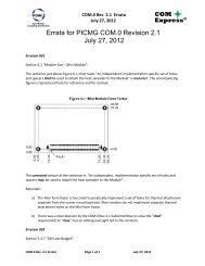
Figure 1-2 General orientation and insertion of <strong>AMC</strong> Modules<br />
Single-Width,<br />
Full-Height<br />
<strong>AMC</strong> Module<br />
<strong>AMC</strong> Connector<br />
<strong>AMC</strong> Guide Rails<br />
Note:<br />
Figure 1-2 is shown without the Side 1 Component Cover.<br />
1.2.4.1 Multi-Width modules<br />
<strong>AMC</strong> supports two Module width definitions: Single-Width and Double-Width.<br />
• Single-Width Modules: The standard width for an <strong>AMC</strong> Module is approximately 74 mm and is referred<br />
to as a Single-Width Module. A maximum of four Single-Width Modules fit across an ATCA Carrier board<br />
as shown in Figure 1-2. (Can be abbreviated as 1x Module.)<br />
• Double-Width Modules: <strong>AMC</strong>.0 also supports a Double-Width Module whose width is roughly twice that<br />
of a Single-Width Module at approximately 149 mm. The wider Module enables designs that would<br />
otherwise not fit on a Single-Width implementation. Double-Width Modules utilize a single <strong>AMC</strong><br />
Connector. A maximum of two Double-Width Modules are designed to fit across an ATCA Carrier board.<br />
(Can be abbreviated as 2x Module.)<br />
A mixture of both Single-Width and Double-Width Modules is permitted (see Figure 1-3). It is important to note that<br />
while most illustrations demonstrate Carrier boards fully populated with <strong>AMC</strong>s, this is not a requirement. It is also<br />
important to note that some designs may only support one or two Single-Width <strong>AMC</strong> Modules.<br />
PICMG <strong>AMC</strong>.0 <strong>Short</strong> Form <strong>Spec</strong>ification Version <strong>D0.9</strong>a<br />
Page 5 of 57
Figure 1-3 Single-Width and Double-Width Full-Height Module Configuration<br />
Double-Width,<br />
Full-Height<br />
Module<br />
Single-Width,<br />
Full-Height<br />
Modules<br />
Note:<br />
Figure 1-3 is shown without the Side 1 Component Cover.<br />
1.2.4.2 Multi-height Modules<br />
<strong>AMC</strong> defines two standard height configurations: Half-Height Modules and Full-Height Modules.<br />
Full-Height Modules: Full-Height Modules are defined to maximize the amount of component and thermal space<br />
available on Component Side 1 of the <strong>AMC</strong> Module. Full-Height Modules cannot be stacked. (See Figure 1-3,<br />
Figure 1-6, and Figure 1-9.)<br />
Half-Height Modules: Half-Height Modules are similar to Full-Height Modules, with the exception of reduced<br />
component space on the Module’s Component Side 1 (See Figure 1-4, Figure 1-7, and Figure 1-8). The term “Half-<br />
Height” implies that two Modules equally split the maximum height available in a stacked implementation and<br />
should not be taken literally as being half of a Full-Height Module.<br />
Table 1-1 presents a general analysis of the different types of connectors that fit on both Half-Height and Full-Height<br />
Modules.<br />
Table 1-1 Connectors that fit Half-Height and Full-Height Modules<br />
Connector types Full-Height Half-Height<br />
XPAK (low profile) Yes (1 on a 1x; 3 on a 2x) Yes (1 on a 1x; 3 on a 2x)<br />
XPAK2 (X2 MSA)<br />
(low profile)<br />
Yes (1 on a 1x; 3 on a 2x)<br />
Yes (1 on a 1x; 3 on a 2x)<br />
(Subject manufacturer<br />
specified pin length)<br />
XENPAK Yes (1 on a 1x; 3 on a 2x) No<br />
SFP (MiniGBIC) Yes (4 max. -1x) Yes - (4 max.-1x)<br />
RJ-45 Yes (4 max. -1x) Yes - (4 max.-1x)<br />
PICMG <strong>AMC</strong>.0 <strong>Short</strong> Form <strong>Spec</strong>ification Version <strong>D0.9</strong>a<br />
Page 6 of 57
Table 1-2 presents a general assessment of a variety of <strong>AMC</strong> Modules that would typically be expected to fit on the<br />
configurations identified.<br />
Table 1-2 Sample Module configurations and functionality<br />
<strong>AMC</strong> Module configurations<br />
Single-Width, Half-Height<br />
Single-Width, Half-Height and<br />
Full-Height<br />
Double-Width, Half-Height and<br />
Full-Height<br />
Example functionality<br />
Disk Drive, DSP Array, FPGA Array, Encryption Engine, T1/E1/J1 Line<br />
Cards, T3/E3 Line Cards, OC-3/12/48 Line Cards, GbE WAN Cards,<br />
10 GbE Optical WAN Card, InfiniBand WAN Card, Memory Arrays<br />
CPU Boards, DOCSIS Cable Modem, Baseband Modem, Radio Cards<br />
NPU Boards<br />
1.2.4.3 Carrier types<br />
<strong>AMC</strong> supports three types of Carrier board configurations.<br />
• Conventional Carriers: The term Conventional Carrier refers to a full Carrier board without any required<br />
cutouts and allows components to be placed on the Carrier below <strong>AMC</strong> Modules. Conventional Carriers<br />
support both Full-Height and Half-Height Modules (see Figure 1-6 and Figure 1-7). Conventional Carriers<br />
also support up to four Single-Width or two Double-Width Modules across an ATCA Carrier board.<br />
• Cutaway Carriers: The term Cutaway Carrier is derived from the fact that the Carrier board below the<br />
<strong>AMC</strong> Modules must be cut-away to support Stacked Modules (see Figure 1-4). By cutting the Carrier<br />
Board, this permits the maximum component height possible for Half-Height Modules and ensures the<br />
needed space for I/O interfaces on the Face Plate (see Figure 1-8). Full-Height Modules can be inserted<br />
into the upper Bay of a Cutaway Carrier when the lower Bay is unoccupied (see Figure 1-9). Cutaway<br />
Carriers can support up to eight Single-Width, Half-Height Modules (see Figure 1-4) or four Double-<br />
Width, Half-Height Modules across an ATCA Carrier board. A maximum stacking of two Modules is<br />
permitted.<br />
• Hybrid Carriers. Hybrid Carriers combine both Conventional and Cutaway Carrier sites on a single<br />
Carrier board.<br />
PICMG <strong>AMC</strong>.0 <strong>Short</strong> Form <strong>Spec</strong>ification Version <strong>D0.9</strong>a<br />
Page 7 of 57
Figure 1-4 Single-Width, Stacked Modules on a Cutaway Carrier<br />
Note:<br />
Figure 1-4 is shown without the Side 1 Component Cover.<br />
1.2.4.4 Connector types<br />
<strong>AMC</strong>.0 defines two fundamental Connector types to support Single-Layer and Stacked Module implementations: B<br />
and AB.<br />
• B Connector:The B Connector is used in association with Conventional Carriers and can support a Single-<br />
Layer Module implementation. Both Full-Height and Half-Height Modules are supported (see Figure 1-6<br />
and Figure 1-7).<br />
• AB Connector:The AB Connector is used in association with Cutaway Carriers and supports up to two<br />
Stacked Half-Height Modules or one Single-Layer Full-Height Module in the upper Bay when the lower<br />
Bay is not occupied. (See Figure 1-8 and Figure 1-9).<br />
Figure 1-5 Overview of <strong>AMC</strong> Connector housings<br />
86<br />
85<br />
86<br />
Slot B<br />
85<br />
86<br />
Slot A<br />
85<br />
170<br />
1<br />
170<br />
85<br />
85<br />
1<br />
1<br />
170<br />
1<br />
Style B/B+<br />
1<br />
Style AB<br />
Style A+B+<br />
PICMG <strong>AMC</strong>.0 <strong>Short</strong> Form <strong>Spec</strong>ification Version <strong>D0.9</strong>a<br />
Page 8 of 57
1.2.4.4.1 Basic and Extended Connectors<br />
<strong>AMC</strong> Modules use a card-edge connection style, which consists of conductive traces at the edge of the Module PCB.<br />
The conductive traces at the edge of the <strong>AMC</strong> act as male pins, which mate to a female connector mounted on the<br />
Carrier board.<br />
<strong>AMC</strong> supports two Connector styles in association with the B and AB Connectors: Basic and Extended.<br />
• Basic Connector: The term “Basic” is associated with <strong>AMC</strong> Connectors that are equipped with<br />
conductive traces on only one side of the Connector. This provides cost and real estate savings for designs<br />
that do not need a large amount of I/O connectivity. The mating Connector for the single-sided design<br />
contains 85 pins and is designated simply as either B or AB. (See Figure 1-5.)<br />
• Extended Connector: The Extended Connector is equipped with conductive traces on both sides of the<br />
Module edge. The mating connector for the two-sided design contains 170 pins per <strong>AMC</strong> Connector and is<br />
designated with a “+” following the connector type (e.g., B+ and A+B+).<br />
1.2.4.5 Module Orientation on a Conventional Carrier<br />
<strong>AMC</strong> Modules on a Conventional Carrier are placed such that Component Side (B1) of the Module faces the Carrier<br />
board (see Figure 1-6). The mechanical envelope is optimized for Single-Layer Full-Height Modules, which allow<br />
for taller components towards the front portion of the Module. This mechanical envelope is maintained for both Full-<br />
Height and Half-Height Modules so as to encourage industry interoperability (see Figure 1-7). Additional<br />
components may be placed on Component Side 2 (B2) of the Module.<br />
Figure 1-6 Full-Height Module orientation in a Conventional Carrier<br />
Module B<br />
Component Side B1<br />
Component Side B2<br />
B/B+<br />
Connector<br />
Conventional Carrier<br />
Carrier Board Components<br />
Figure 1-7 Half-Height Module orientation in a Conventional Carrier<br />
Module B<br />
Component Side B1<br />
Component Side B2<br />
B/B+<br />
Connector<br />
Conventional Carrier<br />
Carrier Board Components<br />
1.2.4.6 Module orientation on a Cutaway Carrier<br />
Cutaway Carriers are designed to enable Stacked Half-Height Modules. The Stacked Modules are oriented such that<br />
Component Side 1 of each <strong>AMC</strong> Module faces in the same direction towards where the Carrier board would be.<br />
Additional Components may be placed on Component Side 2 (A2 or B2) of each <strong>AMC</strong> Module (see Figure 1-8).<br />
Cutaway Carriers also may support a Single-Layer Full-Height Module in the B/B+ layer only (see Figure 1-9).<br />
PICMG <strong>AMC</strong>.0 <strong>Short</strong> Form <strong>Spec</strong>ification Version <strong>D0.9</strong>a<br />
Page 9 of 57
Figure 1-8 Stacked, Half-Height Module orientation in a Cutaway Carrier<br />
Modules<br />
A B<br />
Component Side B1<br />
Component Side A1<br />
Component Side B2<br />
Component Side A2<br />
AB/A+B+<br />
Connector<br />
Cutaway Carrier<br />
Figure 1-9 Single-Layer, Full-Height Module in Cutaway Carrier<br />
Component Side B2<br />
AB/A+B+<br />
Connector<br />
Module B<br />
Component Side B1<br />
Cutaway Carrier<br />
1.2.4.7 Component Covers<br />
A metal encasement above (Side 1 Component Cover) and below (Side 2 Component Cover) the <strong>AMC</strong> configuration<br />
provides the additional strength and rigidity needed, as well as support for <strong>AMC</strong> Guide Rails (see Figure 1-1.) These<br />
plates are required for both Conventional and Cutaway Carrier configurations wherever <strong>AMC</strong> Bays are located.<br />
1.2.4.8 Module management<br />
Module management is optimized for an ATCA environment. Other platforms may require extensions to<br />
accommodate the <strong>AMC</strong> Modules. A management controller is located on every mezzanine which supports a minimal<br />
subset of IPMI commands. The intent of this subset of commands is to minimize both the size and the cost of the onboard<br />
controller. This specification also provides unique geographical address lines for each Module’s IPMI address.<br />
The Module’s management controller communicates with the Carrier board using IPMB.<br />
1.3 Conformance<br />
Do not specify or claim compliance with this <strong>Short</strong> Form version of the <strong>AMC</strong>.0 <strong>D0.9</strong>a <strong>Spec</strong>ification. See the<br />
complete specification for guidelines regarding any statement of compliance.<br />
1.4 Unit measurements<br />
1.4.1 Dimensions<br />
All dimensions in this standard are in millimeters (mm) unless otherwise specified. Drawings are not to scale.<br />
1.4.2 Pressures and airflows<br />
Pressures and airflows are in English units<br />
PICMG <strong>AMC</strong>.0 <strong>Short</strong> Form <strong>Spec</strong>ification Version <strong>D0.9</strong>a<br />
Page 10 of 57
1.5 Reference specifications<br />
The following publications are used in conjunction with this standard. When any of the referenced specifications are<br />
superseded by an approved revision, that revision shall apply. All documents may be obtained from their respective<br />
organizations.<br />
• AdvancedTCA Base <strong>Spec</strong>ification document (PICMG 3.0 R1.0) and as amended by ECN 3.0-1.0-001<br />
• ANSI/TIA/EIA-644-A-2001: Electrical Characteristics of Low Voltage Differential Signaling (LVDS)<br />
Interface Circuits, January 1, 2001<br />
• IPMI – Intelligent Platform Management Bus Communications Protocol <strong>Spec</strong>ification V1.0 Document<br />
Revision 1.0, November 15, 1999 Copyright © 1998, 1999 Intel Corporation, Hewlett-Packard Company,<br />
NEC Corporation, Dell Computer Corporation. All rights reserved.<br />
• IPMI – Intelligent Platform Management Interface <strong>Spec</strong>ification, v1.5. Document Revision 1.1, February<br />
20, 2002. Copyright © 1999,2000, 2001, 2002 Intel Corporation, Hewlett-Packard Company, NEC<br />
Corporation, Dell Computer Corporation. All rights reserved.<br />
• IPMI – Platform Event Trap Format <strong>Spec</strong>ification V1.0 Document Revision 1.0, December 7, 1998<br />
Copyright © 1998, Intel Corporation, Hewlett-Packard Company, NEC Corporation, Dell Computer<br />
Corporation. All rights reserved.<br />
• IPMI – Platform Management FRU Information Storage Definition, V1.0 Document Revision 1.1,<br />
September 27, 1999 Copyright © 1998, 1999 Intel Corporation, Hewlett-Packard Company, NEC<br />
Corporation, Dell Computer Corporation. All rights reserved.<br />
• IPMI – Wired for Management Baseline, Version 2.0.<br />
• PICMG ® Policies and Procedures for <strong>Spec</strong>ification Development, Revision 1.5, October 5, 2001, PCI<br />
Industrial Computer Manufacturers Group (PICMG ® ), 401 Edgewater Place, Suite 500, Wakefield, MA<br />
01880 USA, Tel: 781.224.1100, Fax: 781.224.1239, www.<strong>picmg</strong>.org<br />
1.6 <strong>Spec</strong>ial word usage<br />
This document uses the following key words:<br />
may:Indicates the flexibility of choice with no implied preference.<br />
should:Indicates flexibility of choice with a strongly preferred implementation. The use of should not (in bold text)<br />
indicates flexibility of choice with a strong preference that the choice or implementation be prohibited.<br />
shall:Indicates a mandatory requirement. Designers shall implement such mandatory requirements to ensure<br />
interoperability and to claim conformance with this specification. The use of shall not (in bold text) indicates an<br />
action or implementation that is prohibited.<br />
1.7 Intellectual property<br />
Lucent Technologies has a patent, US #6646890, referring to “Mounting of mezzanine circuit boards to a base<br />
board.” This patent, filed on 9/4/02 and issued on 11/11/03, may cover aspects of the guide mechanisms that are<br />
detailed in the <strong>AMC</strong>.0 specification.<br />
1.8 Glossary<br />
Definitions of terms and acronyms as they are used in this document have been grouped as follows:<br />
• Table 1-3, “<strong>AMC</strong> Carrier specific terms”<br />
• Table 1-4, “<strong>AMC</strong> Module specific terms”<br />
PICMG <strong>AMC</strong>.0 <strong>Short</strong> Form <strong>Spec</strong>ification Version <strong>D0.9</strong>a<br />
Page 11 of 57
• Table 1-5, “<strong>AMC</strong> Connector or Interface specific terms”<br />
Table 1-3 <strong>AMC</strong> Carrier specific terms<br />
Term or acronym<br />
<strong>AMC</strong> Carrier or<br />
Carrier<br />
<strong>AMC</strong> Bay or Bay<br />
Component Cover<br />
Conventional<br />
Carrier<br />
Cutaway Carrier<br />
Hybrid Carrier<br />
Partial Carrier<br />
Description<br />
“<strong>AMC</strong> Carrier” is used to describe Carrier boards that support <strong>AMC</strong> Modules. The<br />
abbreviated “Carrier” may optionally be used when the context of <strong>AMC</strong> is well<br />
understood.<br />
An <strong>AMC</strong> Bay is a single <strong>AMC</strong> site on an <strong>AMC</strong> Carrier and can support either Stacked<br />
or Single-Layer Modules.<br />
Board Covers provide mechanical rigidity for the Carrier boards as well as a place to<br />
mount the Module Guide Rails and the <strong>AMC</strong> connector body. Conductive board<br />
covers are required on both sides of all <strong>AMC</strong> Carrier board configurations and are<br />
referred to as Side 1 Component Cover and Side 2 Component Cover.<br />
The term Conventional Carrier refers to a full Carrier board without any required<br />
cutouts and allows components to be placed on the Carrier below <strong>AMC</strong> Modules.<br />
Conventional Carriers support both Full-Height and Half-Height Modules (see<br />
Figure 1-5 and Figure 1-6). Conventional Carriers also support up to four Single-<br />
Width or two Double-Width Modules across an ATCA Carrier board.<br />
The term Cutaway Carrier is derived from the fact that the Carrier board below the<br />
<strong>AMC</strong> Modules must be cut away to support Stacked Modules (see Figure 1-4).<br />
Cutting the Carrier Board permits the maximum component height possible for Half-<br />
Height Modules and ensures the needed space for I/O interfaces on the Face Plate<br />
(see Figure 1-7). Full-height Modules can be inserted into the upper Bay of a<br />
Cutaway Carrier when the lower Bay is unoccupied (see Figure 1-8). Cutaway<br />
Carriers can support up to eight Single-Width, Half-Height Modules (as shown in<br />
Figure 1-4) or four Double-Width, Half-Height Modules across an ATCA Carrier<br />
board. A maximum stacking of two Modules is permitted.<br />
An <strong>AMC</strong> Carrier that has both Conventional and Cutaway sites and includes both<br />
B/B+ and AB/A+B+ connector types. Assumes the Carrier board is fully populated<br />
with <strong>AMC</strong> Modules. (Also, see Partial Carrier.)<br />
Any <strong>AMC</strong> Carrier that is not fully populated with <strong>AMC</strong> Modules (e.g., a Carrier that<br />
includes only two <strong>AMC</strong> Bays). The following Partial Carrier types are possible: Partial<br />
Conventional Carrier, Partial Cutaway Carrier, and Partial Hybrid Carrier.<br />
.<br />
Table 1-4 <strong>AMC</strong> Module specific terms<br />
Term or acronym<br />
<strong>AMC</strong> Module or<br />
Module<br />
Double-Width<br />
Module<br />
Full-Height<br />
Module<br />
Half-Height<br />
Module<br />
Module Guide Rail<br />
Single-Layer<br />
Module<br />
Description<br />
An <strong>AMC</strong> Module (or Module) is a modular add-on or “child” card that extends the<br />
functionality of a Carrier board. An <strong>AMC</strong> Module can also be referred to as a<br />
mezzanine. The term is also used to generically refer to the different varieties of<br />
Multi-Width and Multi-Height Modules.<br />
A Module that is roughly twice the width of a Single-Width <strong>AMC</strong> Module and requires<br />
two <strong>AMC</strong> Bays. A maximum of two Double-Width Modules are designed to fit across<br />
an ATCA Carrier.<br />
Full-Height Modules allow for taller components on Component Side 1 of the Module<br />
but otherwise are identical to Half-Height Modules.<br />
The component height on Component Side 1 of Half-Height Modules is optimized to<br />
allow for two Stacked Modules to equally split the maximum height (ATCA pitch)<br />
available. The term Half-Height should not be taken literally as being half of a Full-<br />
Height Module.<br />
Guide Rail utilized by <strong>AMC</strong> Modules to facilitate insertion into the <strong>AMC</strong> Bay and to<br />
help facilitate Hot Swap of Modules.<br />
Used to describe the presence of a single <strong>AMC</strong> Module in an <strong>AMC</strong> Bay and is always<br />
used in connection with Full-Height Modules.<br />
PICMG <strong>AMC</strong>.0 <strong>Short</strong> Form <strong>Spec</strong>ification Version <strong>D0.9</strong>a<br />
Page 12 of 57
Table 1-4 <strong>AMC</strong> Module specific terms (Continued)<br />
Term or acronym<br />
Single-Width<br />
Module<br />
Stacked<br />
Modules<br />
Description<br />
The standard (1x) width of an <strong>AMC</strong> Module that fits into a single <strong>AMC</strong> Bay.<br />
Used to describe two Half-Height Modules that are “stacked” one above another<br />
using an AB/A+B+ Connector.<br />
.<br />
Table 1-5 <strong>AMC</strong> Connector or Interface specific terms<br />
Term or acronym<br />
A Layer<br />
AB/A+B+<br />
Connector<br />
<strong>AMC</strong> Connector or<br />
Connector<br />
B Layer<br />
Basic Connector<br />
Basic Side<br />
B/B+ Connector<br />
Contact List<br />
Connector Brace<br />
Extended<br />
Connector<br />
Extended Side<br />
LVDS or<br />
High-Speed LVDS<br />
Link<br />
M-LVDS<br />
Port<br />
Description<br />
Module orientation when inserted into the lower Bay of an AB/A+B+ Connector. It is<br />
located in the cutout section of a Cutaway Carrier and is utilized by Half-Height<br />
Modules only.<br />
An <strong>AMC</strong> Connector that supports two <strong>AMC</strong> Bays. The AB designation indicates<br />
support as Basic Connectors. The “+” designation indicates support as Extended<br />
Connectors.<br />
Used to generically refer to <strong>AMC</strong> defined connectors including B/B+ and AB/A+B+.<br />
Module orientation when inserted into B/B+ Connector or into the upper Bay of an<br />
AB/A+B+ Connector.<br />
Requires conductive traces on only one side of the connector and supports all the<br />
mandatory aspects of the connector definition including <strong>AMC</strong> power and<br />
management. The mating connector for the single-sided design contains 85 contacts<br />
per Bay and is designated simply as B or AB. The Basic Connector supports 8 ports.<br />
Refers to the side of the <strong>AMC</strong> Connector that supports a Basic Connector.<br />
An <strong>AMC</strong> Connector that supports a single <strong>AMC</strong> Bay. The B designation indicates<br />
support as a Basic Connector. The “+” designation indicates support as an Extended<br />
Connector.<br />
Defines the use of each contact and is identical for both the <strong>AMC</strong> Module and<br />
Connector.<br />
A stiffener that is mounted on Component Side 2 of the Carrier board, opposite the<br />
<strong>AMC</strong> Connector and used to help prevent the Carrier board from bending.<br />
Requires conductive traces on each side of the Connector and includes the Basic<br />
Connector definition. The mating connector for the two-sided design contains 170<br />
contacts per Bay and is designated with the “+” designation (i.e., B+ and A+B+).<br />
Refers to the side of the <strong>AMC</strong> Connector associated with the additional support<br />
provided by an Extended Connector.<br />
Refers to Low Voltage Differential Signaling and defined in ANSI/EIA-644-A.<br />
One or more Ports aggregated under a common protocol. Links are groups of Ports<br />
that are enabled and disabled by Electronic Keying operations. A xN Link<br />
(pronounced “by-N link”) is composed of N Ports.<br />
A later development of LVDS defined in ANSI/TIA/EIA-644. It is specifically designed<br />
for multi-drop and multi-sourced signaling.<br />
A set of differential signal pairs, one pair for transmission and one pair for reception.<br />
(Note: The PCI Express term “Lane” is equivalent to the <strong>AMC</strong>.0 term “Port”.)<br />
PICMG <strong>AMC</strong>.0 <strong>Short</strong> Form <strong>Spec</strong>ification Version <strong>D0.9</strong>a<br />
Page 13 of 57
Mechanical 2<br />
2.1 Modules<br />
2.1.1 Module PCB dimensions<br />
Modules shall have all 170 gold plated pads and pre-pads regardless of whether they are electrically required or not in<br />
order to protect the contacts of the connectors.<br />
The Module contacts shall be electroplated 0.4 µm hard gold over 1.3 µm nickel.<br />
The Module keepout areas shall exclude all components, traces, test points, vias, and features that can form a<br />
mechanical impediment or provide an electrical conduction including traces protected by solder mask.<br />
2.1.1.1 Single-Width Module PCB dimensions<br />
Figure 2-1 Single-Width Module PCB dimensions<br />
PICMG <strong>AMC</strong>.0 <strong>Short</strong> Form <strong>Spec</strong>ification Version <strong>D0.9</strong>a<br />
Page 14 of 57
2.1.1.2 Double-Width Module PCB dimensions<br />
Figure 2-2 Double-Width Module PCB dimensions<br />
PICMG <strong>AMC</strong>.0 <strong>Short</strong> Form <strong>Spec</strong>ification Version <strong>D0.9</strong>a<br />
Page 15 of 57
2.1.1.3 Module Connector interface dimensions<br />
Figure 2-3 Module Connector interface dimensions<br />
PICMG <strong>AMC</strong>.0 <strong>Short</strong> Form <strong>Spec</strong>ification Version <strong>D0.9</strong>a<br />
Page 16 of 57
Figure 2-4 Module edge contact detail<br />
2.1.2 Module component height requirements<br />
The maximum Module component heights shall not exceed those shown in the profiles in Figure 2-5 and Figure 2-6;<br />
these show Half-Height Modules with a total component envelope of 11.58 mm and Full-Height Modules with a total<br />
component envelope of 17.91 mm for the front 100 mm and 15.85 mm for the rear 73 mm.<br />
Full-Height Modules shall be supported in the B-Layer only.<br />
PICMG <strong>AMC</strong>.0 <strong>Short</strong> Form <strong>Spec</strong>ification Version <strong>D0.9</strong>a<br />
Page 17 of 57
2.1.3 Module Face Plate<br />
Module Face Plates fulfill a series of tasks:<br />
• Support for the latch mechanism<br />
• Mounting surface for I/O connectors<br />
• EMC containment<br />
• Mounting and mating of EMC gasket surfaces<br />
• Mechanical interface to the <strong>AMC</strong> PCB<br />
• ESD shield<br />
• Mounting for LED displays<br />
• Mounting and display of product information<br />
2.1.4 Module Face Plate labels<br />
Figure 2-5 Vendor and PICMG label dimensioning and positioning<br />
PICMG <strong>AMC</strong>.0 <strong>Short</strong> Form <strong>Spec</strong>ification Version <strong>D0.9</strong>a<br />
Page 18 of 57
2.1.5 Carrier PCB dimensions<br />
2.1.5.1 Cutaway Carrier board dimensions<br />
Figure 2-6 Cutaway Carrier using AB Connector dimensions<br />
PICMG <strong>AMC</strong>.0 <strong>Short</strong> Form <strong>Spec</strong>ification Version <strong>D0.9</strong>a<br />
Page 19 of 57
2.1.5.2 Conventional Carrier board dimensions<br />
Figure 2-7 Conventional Carrier board dimensions<br />
2.1.6 Carrier component height requirements<br />
All component heights that are not below the Module, with the exception of the <strong>AMC</strong> Connector, shall conform to all<br />
PICMG 3.0 specifications or the relevant requirements for other form factors.<br />
PICMG <strong>AMC</strong>.0 <strong>Short</strong> Form <strong>Spec</strong>ification Version <strong>D0.9</strong>a<br />
Page 20 of 57
2.1.6.1 Conventional Carriers<br />
These dimensions are also applicable to the Conventional Carrier portion of Hybrid Carriers. See relevant<br />
requirements for other form factors.<br />
Figure 2-8 Conventional Carrier component heights<br />
2.1.6.2 Cutaway Carriers<br />
Cutaway Carriers mandate that the Carrier board PCB be removed below the <strong>AMC</strong> Module sites. Therefore, there are<br />
no <strong>AMC</strong>-controlled Carrier board component heights.<br />
2.1.7 Card guides and struts<br />
The component covers provide a means of mounting removable and non-removable channels on which the edges of<br />
Module PCB boards ride in or ride out. These are known as <strong>AMC</strong> card guides.<br />
PICMG <strong>AMC</strong>.0 <strong>Short</strong> Form <strong>Spec</strong>ification Version <strong>D0.9</strong>a<br />
Page 21 of 57
2.1.7.1 A Layer<br />
Figure 2-9 Card guide A Layer assembly dimensions<br />
PICMG <strong>AMC</strong>.0 <strong>Short</strong> Form <strong>Spec</strong>ification Version <strong>D0.9</strong>a<br />
Page 22 of 57
Figure 2-10 A Layer card guide and strut parts dimensions<br />
PICMG <strong>AMC</strong>.0 <strong>Short</strong> Form <strong>Spec</strong>ification Version <strong>D0.9</strong>a<br />
Page 23 of 57
2.1.7.2 B Layer<br />
Figure 2-11 Card guide B Layer assembly dimensions<br />
PICMG <strong>AMC</strong>.0 <strong>Short</strong> Form <strong>Spec</strong>ification Version <strong>D0.9</strong>a<br />
Page 24 of 57
Figure 2-12 B Layer card guide and strut parts dimensions<br />
PICMG <strong>AMC</strong>.0 <strong>Short</strong> Form <strong>Spec</strong>ification Version <strong>D0.9</strong>a<br />
Page 25 of 57
Module management 3<br />
3.1 Overview<br />
The management aspects of Modules are intended to be platform agnostic. Although the Module specification is<br />
developed with ATCA in mind, it is the intent of the management architecture to support Modules in ATCA-based<br />
Carrier cards as well as platforms that might be exclusively Module-based or platforms that mix Modules with other<br />
form factors. In defining the role of the Module in system management it has been the intent of this section to<br />
minimize the management burden on the Module where space is a premium. Modules are controlled by a<br />
management controller with minimal functionality called the Module Management Controller or MMC. The<br />
commands that the MMC must support are intended to be a bare minimum in order to lower the cost of the MMC and<br />
save space on the Module. The Carrier IPMC communicates with a Module’s MMC using IPMI messages over<br />
IPMB. This specification provides unique geographical address lines for each Module’s IPMB-L address.<br />
Figure 3-1 Module Management Infrastructure<br />
Shelf External System<br />
Manager<br />
Shelf<br />
Manager<br />
Active<br />
ShMC<br />
Shelf<br />
Manager<br />
Standby<br />
ShMC<br />
ATCA Board<br />
2x Redundant, Bussed or Radial, IPMB-0<br />
ATCA Carrier Board<br />
IPMC<br />
IPMC<br />
Bussed or Radial, IPMB-L<br />
isolator<br />
isolator<br />
isolator<br />
isolator<br />
MMC<br />
MMC<br />
MMC<br />
MMC<br />
<strong>AMC</strong><br />
<strong>AMC</strong><br />
<strong>AMC</strong><br />
<strong>AMC</strong><br />
3.1.1 IPMI and IPMB architecture overview<br />
The Carrier and Module communicate through a limited set of IPMI commands. The intent is to allow the use of<br />
inexpensive single chip microcontrollers on the Module. This specification requires that the Carrier provide ways to<br />
isolate the IPMB to each Module. This was done to prevent a Module from bringing down the IPMB. The<br />
specification also envisions that the Carrier might have multiple IPMBs. For clarity, the term IPMB-0 refers to the<br />
AdvancedTCA IPMB and the term IPMB-L refers to the IPMB between the Carrier and Module. The IPMB-L could<br />
either be radial or bussed as desired by the Carrier board designer. The IPMB-0 and IPMB-L are physically separate<br />
busses and in general the Carrier is responsible for bridging the two as necessary.<br />
PICMG <strong>AMC</strong>.0 <strong>Short</strong> Form <strong>Spec</strong>ification Version <strong>D0.9</strong>a<br />
Page 26 of 57
Note:<br />
Intelligent controllers are referred to as an MMC on an <strong>AMC</strong> and as an IPMC on Carriers.<br />
3.1.2 Module and Carrier power architecture overview<br />
The Carrier provides management and payload power to a Module. Management power is used to power the<br />
management circuitry in the Module. The management circuitry includes the MMC, and pullups for IPMB-L and<br />
ENABLE#. Management power is current-limited by the Carrier. An MMC reset is provided from the Carrier. The<br />
Carrier will hold the MMC in reset until the Module is fully inserted. The MMC reset can also be controlled by the<br />
Carrier in the event that it becomes necessary to reset the MMC. Payload power (PWR) is the power provided to the<br />
Module from the Carrier for the main function of the Module. The Module FRU information contains records that<br />
define the PWR requirements for the payload. A Carrier will enable PWR if it determines that enough power and<br />
cooling exist to support the Module.<br />
3.2 Module management interconnects<br />
Figure 3-2 shows the interconnections between the Module and Carrier. Note that active low signals are denoted with<br />
a trailing #. All logic levels are assumed to be 3.3 V compatible unless noted.<br />
Figure 3-2 Interconnections between Carrier and Module<br />
GA_PULLUP<br />
Module<br />
MP<br />
Carrier<br />
Module<br />
Management<br />
Pow er<br />
MMC<br />
3.3K 33K<br />
10K<br />
GA[2..0]<br />
IPMB-L<br />
2.2K<br />
IPMB-L_Isolator<br />
RESET#<br />
ENABLE#<br />
Reset_MMC#<br />
From IPMC<br />
PS1#<br />
PS0#<br />
3.2.1 Geographic address [2..0] (GA[2..0])<br />
There are three geographic address pins which are used to assign the address of the Module on the local IPMB-L.<br />
Each of the GA pins can encode three different levels. The GA (Geographic Address) lines can be connected to<br />
ground, to management power, or left unconnected on the Carrier to define the geographic address of the Module.<br />
This scheme requires that the Module be able to distinguish between the three states. The states of the GA bits can be<br />
G (grounded), U (unconnected), and P (pulled up to management power).<br />
PICMG <strong>AMC</strong>.0 <strong>Short</strong> Form <strong>Spec</strong>ification Version <strong>D0.9</strong>a<br />
Page 27 of 57
3.2.2 PS0# and PS1#<br />
PS0# and PS1# pins are used to detect the presence of a Module in a Carrier. The PS pins are last mate pins located on<br />
opposite sides of the connector. These pins are used to de-skew the connector and provide an indication that all pins<br />
on the Module connector have mated. The Carrier connects PS0# to GND and PS1# to a management power pullup<br />
resistor. The Module provides a low resistance path between PS0# and PS1#. The Carrier can detect the presence of a<br />
Module by a low on PS1#.The Module can determine insertion into a Carrier by the Carrier’s feedback of PS0# and<br />
PS1# on ENABLE# as well as current flowing through the PS0# - PS1# connection.<br />
3.2.3 ENABLE#<br />
The Enable pin is an active low input to the Module pulled up on the Module to management power. This signal is<br />
inverted on the Module to create an MMC RESET# signal. This input indicates to the Module that the Module is fully<br />
inserted and valid states exist on all inputs to the Module. The MMC is not allowed to read the GA inputs or use the<br />
IPMB-L while ENABLE# is inactive. Note that the payload power decisions are made by the higher level entity and<br />
the Carrier executes that decision.<br />
3.2.4 IPMB-L<br />
The IPMB-L is made up of clock (SCL_L) and data (SDA_L) signals. These signals are to be considered valid by the<br />
Module when ENABLE# is active. Each Module receives an isolated copy of the IPMB-L. This isolated IPMB can be<br />
provided using FET type switches or I 2 C buffers.<br />
3.2.5 BLUE LED<br />
The BLUE LED is local to the Module. The BLUE LED is mounted on the front of the Module and is used to provide<br />
basic feedback to the user on the Hot Swap state of the Module. The BLUE LED states are off, short blink, long blink,<br />
and on. Once management power is available to the Module, the BLUE LED is turned 100% on as soon as possible.<br />
3.2.6 LED 1 (mandatory)<br />
LED 1 typically provides basic feedback about failures and out of service.<br />
3.2.7 Hot Swap switch<br />
The Hot Swap switch input connects to the mechanical latching mechanism. This switch is used to indicate a request<br />
for a pending extraction. This switch is pulled up to management power so that it can be read when payload power is<br />
not applied. The Module sends an IPMI platform event message to the Carrier when the Hot Swap switch changes<br />
state.<br />
3.2.8 Payload reset<br />
The payload reset is local to the Module. This signal is used by the MMC to reset the payload when a FRU Control<br />
command is issued by the Carrier IPMC.<br />
3.2.9 Watchdog timer<br />
A watchdog timer is provided to reset the MMC in the event that the MMC is unresponsive. The watchdog could be<br />
integrated into the MMC. This specification does not mandate what the watchdog checks; just that a watchdog be<br />
provided to reset an unresponsive MMC. Note that the state of the payload cannot be impacted if an MMC watchdog<br />
timer reset occurs.<br />
PICMG <strong>AMC</strong>.0 <strong>Short</strong> Form <strong>Spec</strong>ification Version <strong>D0.9</strong>a<br />
Page 28 of 57
3.3 Module management-hardware requirements<br />
This section defines the requirements for the interconnects as seen by the Module. Figure 3-3 presents a simplified<br />
block diagram showing the Module interconnects for clarity.<br />
Figure 3-3 Module to Carrier hardware<br />
Module<br />
GA_PULLUP<br />
Carrier<br />
MP<br />
Hot Swap Switch<br />
300 Ohm 10 K<br />
MMC<br />
3.3 K<br />
33 K<br />
10 K<br />
GA[2..0]<br />
IPMB-L<br />
Blue LED<br />
RESET#<br />
ENABLE#<br />
PS1#<br />
PS0#<br />
3.4 Carrier management-hardware requirements<br />
This section defines the interconnect requirements for the Carrier. Figure 3-4 shows a simplified version of the<br />
interconnects on a Carrier for clarity.<br />
Figure 3-4 Carrier and Module interconnects<br />
Module<br />
Carrier<br />
MP<br />
GA[2..0]<br />
IPMB-L<br />
2.2K<br />
Module<br />
Management<br />
Power Control<br />
3.3K<br />
3.3 V<br />
IPMB-L Enable<br />
IPMB<br />
Isolator<br />
IPMB-L<br />
IPMC<br />
ENABLE#<br />
Reset_MMC#<br />
PS1#<br />
PS0#<br />
PICMG <strong>AMC</strong>.0 <strong>Short</strong> Form <strong>Spec</strong>ification Version <strong>D0.9</strong>a<br />
Page 29 of 57
3.5 Power management<br />
This specification insists that the power needs of the Module are not part of the Carrier’s power budget and that the<br />
Modules be treated as separate FRUs and represent their power budget as such. The intelligent power management<br />
decisions for the Modules are made by the Shelf Manager and the Carrier plays the role of a facilitator cum executor<br />
of that decision. A converter is viewed as part of the Carrier’s power budget. An additional criteria is the amount of<br />
power that can be delivered to an <strong>AMC</strong> site. This is typically limited by the trace width.<br />
The final criteria in power management is the amount of power that the Module can consume. As explained in the<br />
AdvancedTCA base specification document (PICMG 3.0 R1.0) and as amended by ECN 3.0-1.0-001, in order to<br />
make intelligent decisions about when the FRUs (in this case, <strong>AMC</strong>s) are powered up or down and what power levels<br />
to assign for each FRU (in this case, <strong>AMC</strong>), the Shelf Manager must collect several pieces of data.<br />
• The Carrier data (provided by the Carrier manufacturer)<br />
–Maximum PWR Current (number 5 in Figure 3-5) that could be that can be delivered to all of the <strong>AMC</strong><br />
sites. This is typically the power rating of the DC-DC converter that generates PWR.<br />
–Maximum FRU Current (number 6 in Figure 3-5) that could be delivered to a particular Module. This is<br />
the maximum amount of current that can be delivered to an <strong>AMC</strong> site in Amps at 12 V.<br />
• The Module power consumption (provided by the Module manufacturer).<br />
–The Power consumed by a Module in Amps (number 7 in Figure 3-5).<br />
Figure 3-5 Power distribution management architecture<br />
4<br />
5<br />
6<br />
7<br />
1<br />
2<br />
3<br />
3<br />
1 Power supplied to the Shelf Power Feed; entered during Shelf installation<br />
2 Power that can be handled by this Feed; entered by Shelf manufacturer<br />
3 Max. Power that can be routed to an ATCA Board; entered by Shelf manufacturer<br />
4 Power required by the ATCA Board; entered by ATCA Board manufacturer<br />
5 Power available to all <strong>AMC</strong> sites; entered by ATCA Board manufacturer<br />
6 Max. Current that can be routed to an <strong>AMC</strong> site; entered by ATCA Board manufacturer<br />
7 Power required by the <strong>AMC</strong>; entered by <strong>AMC</strong> Board manufacturer<br />
Shelf<br />
ATCA Board<br />
<strong>AMC</strong><br />
Defined in<br />
ATCA <strong>Spec</strong>.<br />
Defined in<br />
<strong>AMC</strong> <strong>Spec</strong>.<br />
3.6 Cooling management<br />
To support a higher level managing entity to appropriately manage the cooling resources, the Module has to provide<br />
reports of abnormal temperature in its environment. Every Module has to have a temperature sensor to enable the<br />
Module to report the temperature and this temperature sensor is monitored by the MMC. When an MMC detects that<br />
PICMG <strong>AMC</strong>.0 <strong>Short</strong> Form <strong>Spec</strong>ification Version <strong>D0.9</strong>a<br />
Page 30 of 57
a monitored temperature sensor exceeds one or more thresholds or returns to normal, The MMC raises a standard<br />
IPMI temperature event message and sends it to the event receiver (the Carrier). The Carrier, or a higher level<br />
managing entity, uses this information to manage the cooling.<br />
Every Module must contain at least one temperature sensor and an appropriate Sensor Data Record (SDR) to describe<br />
the sensor.<br />
3.7 E-Keying<br />
Electronic Keying is the mechanism by which the mandatory <strong>AMC</strong>.0 Management infrastructure is used to<br />
dynamically satisfy the needs that had traditionally been satisfied by various mechanical connector keying solutions:<br />
• Prevent mis-operation<br />
• Verify fabric compatibility<br />
Since the <strong>AMC</strong>.0 specification does not allow a direct connection between Modules and the Carrier backplane, the<br />
Carrier must provide one or more switch(es) between the Carrier backplane and the Modules. The IPMC on the<br />
Carrier is responsible for E-Keying between the Modules and switch(es). E-Keying between switch(es) and the<br />
Carrier backplane is out of scope of the <strong>AMC</strong>.0 specification and is covered by PICMG 3.0.<br />
This section uses the terms Control Interface and Data Fabric Interface. These interfaces are made up of a number of<br />
ports. The ports allocated to the Control Interface on a Module or Carrier are typically connected to the ATCA base<br />
interface through an on-Carrier switch. The ports allocated for the Data Fabric Interface would typically connect to<br />
the ATCA fabric.<br />
3.7.1 E-Keying process<br />
The basis for the E-Keying process is the E-Keying entries present as FRU information in the Carrier and all<br />
Modules. Those E-Keying entries describe the Control Interface, and the Data Fabric Interface implemented by the<br />
Carrier and Modules.<br />
3.7.2 Point-to-point E-Keying<br />
Point-to-point E-Keying covers the Control Interface and Data Fabric Interface. In the Data Fabric, the primary unit<br />
of point-to-point connectivity is a Port. A Port is two differential pairs (one transmit and one receive). One to four<br />
Ports can be grouped into a logical <strong>AMC</strong> Channel that is similar to an AdvancedTCA Channel. An <strong>AMC</strong> Channel is<br />
composed of an arbitrary (not necessarily numerically or physically contiguous) set of up to four Ports. In contrast,<br />
any given AdvancedTCA Channel involves a specific set of contiguous zone 2 connector pins.<br />
<strong>AMC</strong> Channels are identified by <strong>AMC</strong> Channel IDs. In the data structures and commands defined in this section,<br />
<strong>AMC</strong> Channel IDs play essentially the same role as Channel numbers in AdvancedTCA E-Keying. <strong>AMC</strong> Channel<br />
IDs start at 0 and are numbered sequentially on a given Carrier or Module. In this specification, each Link is mapped<br />
to a specific <strong>AMC</strong> Channel and an associated protocol. As in AdvancedTCA, a Link can be composed of several<br />
<strong>AMC</strong> Channels (say, to create a x16 PCI Express Link that combines four <strong>AMC</strong> Channels, each representing a x4<br />
connection).<br />
Point-to-Point E-Keying supports two Data Fabric <strong>AMC</strong> Carrier routing models: the centralized <strong>AMC</strong> switch model<br />
and the <strong>AMC</strong> direct connectivity model. The point-to-point connectivity provided in a Carrier is described in the<br />
Carrier FRU information. The capabilities of an <strong>AMC</strong> Module to communicate over point-to-point connections are<br />
described in the Module’s FRU information. Similar information for the links supported by the on-Carrier switch(es)<br />
is provided in the Carrier FRU information. In this topic there are references to Switch ID; these refer to the ID<br />
(number) assigned to an on-Carrier switch. The assignment of the number is arbitrary.<br />
PICMG <strong>AMC</strong>.0 <strong>Short</strong> Form <strong>Spec</strong>ification Version <strong>D0.9</strong>a<br />
Page 31 of 57
3.7.2.1 <strong>AMC</strong> point-to-point interface information<br />
One or more <strong>AMC</strong> point-to-point connectivity records are included in the <strong>AMC</strong> FRU information and describe the<br />
connections to the Control and Data Fabric Interfaces that are implemented on the <strong>AMC</strong> Module. Similarly, one or<br />
more such records are included in the Carrier FRU information to describe the connections to the Control and Data<br />
Fabric Interfaces that are implemented by on-Carrier switch(es). These connections, each consisting of some subset<br />
of the Ports associated with one or more <strong>AMC</strong> Channels, are generically referred to as “Links”.<br />
Each <strong>AMC</strong> point-to-point connectivity record contains <strong>AMC</strong> Link Descriptors, each of which identifies a Link and an<br />
associated protocol.<br />
3.8 Module payload control<br />
The “FRU Control” command provides base level control over the Module’s payload to the Carrier IPMC. Through<br />
this command, the Module’s payload can be reset, rebooted, instructed to attain quiescence, or have its diagnostics<br />
initiated. The exact implementation of these commands will vary according to individual requirements, and all<br />
command variants with the exception of the “FRU Control (Cold Reset)” and “FRU Control (Attain Quiescence” are<br />
optional. The “FRU Control” command does not directly change the operational state of the Module as represented<br />
by the Carrier IPMC (which is typically M4 or FRU Active).<br />
3.9 Module sensor management<br />
MMCs have the capability of supporting any of the IPMI or OEM sensor types (analogous to an IPMC on an ATCA<br />
board). The MMC’s sensors on IPMB-L are visible to the ShMC through the IPMC over IPMB-0. Since the IPMC<br />
must present unique sensor numbers and sensor LUNs over IPMB-0, it is necessary for the IPMC to translate the<br />
MMC’s sensor number and sensor LUN to IPMC-wide unique numbers. The IPMC device SDR repository holds a<br />
combination of its own SDRs and SDRs from MMCs installed on the Carrier. The IPMC adds the MMC’s SDRs into<br />
its SDR Repository after management power has been enabled to the MMC. Conversely, the MMC’s SDRs are<br />
removed from the IPMC’s SDR repository after management power has been removed from an MMC. As mentioned<br />
previously, when an IPMC adds the MMC’s SDRs into its SDR repository, it needs to ensure that the sensor number<br />
and sensor LUN assigned are unique for the IPMC.<br />
The IPMC will also need to provide unique FRU IDs for all MMCs on a Carrier. The local FRU ID for an MMC is<br />
always 0; the IPMC will need to assign unique FRU IDs to all MMCs. MMC SDRs are linked with a Module using<br />
the entity fields of the SDR; the entity ID identifies that SDR as coming from a Module FRU and the entity instance<br />
is set to the Module site number to identify the Module on the Carrier. Also refer to Section 3.4.3 in the<br />
AdvancedTCA base specification document (PICMG 3.0 R1.0) and as amended by ECN 3.0-1.0-001 and to IPMI 1.5<br />
Chapter 33.1 for more information on IPMI entities.<br />
The IPMC will need to maintain a table that would be used to translate the IPMC-wide unique sensor number, sensor<br />
LUN, and FRU ID to the MMC’s sensor number, sensor LUN, and FRU ID. When an IPMC receives a request over<br />
IPMB-0 for an MMC’s sensor or FRU data, the IPMC substitutes the received sensor number, sensor LUN, or FRU<br />
ID with the target MMC’s sensor number, sensor LUN, or FRU ID and sends the request over the IPMB-L to the<br />
MMC. The IPMC then returns the requested data substituting the MMC’s identifying data with the IPMC’s<br />
identifying data. The IPMC is also responsible for redirecting events generated on IPMB-L to the system event<br />
receiver on IPMB-0. In doing so, the IPMC substitutes the event generator ID with its own ID and substitutes the<br />
sensor number and sensor LUN from the received message with the IPMC-wide unique sensor number and sensor<br />
LUN. The message is then transmitted over IPMB-0.<br />
PICMG <strong>AMC</strong>.0 <strong>Short</strong> Form <strong>Spec</strong>ification Version <strong>D0.9</strong>a<br />
Page 32 of 57
3.10 FRU information<br />
All Carriers and Modules must contain a FRU information storage device (for instance, an SEEPROM) that contains<br />
basic information about them. The format of the FRU information follows the requirements set forth in Section 3.6.3,<br />
IPM Controller FRU Information, in the AdvancedTCA base specification document (PICMG 3.0 R1.0) and as<br />
amended by ECN 3.0-1.0-001. In addition to this basic information, additional fields are required to support functions<br />
unique to the Modules.<br />
An early and important feature of system management is its inventory management capability. Sections 1.6.11<br />
through 1.6.14 of the IPMI specification provide an overview of FRU information principles and implementations.<br />
While the IPMI specification highly recommends that each IPMC implement the “FRU Inventory Device”<br />
commands, this document makes that a requirement of each MMC.<br />
The term Field Replaceable Unit (FRU) is used to reference a unit that can be replaced by customers in the field. All<br />
Modules are FRUs.<br />
The term FRU information refers to information stored within the Module in some non-volatile storage location. For<br />
instance, it could be contained in a SEEPROM within the unit. In all cases, the FRU information is accessed through<br />
a controller that knows how to talk to the non-volatile storage within the Module.<br />
3.10.1 FRU information access commands<br />
Access to read or write the FRU information is provided by three IPMI commands directed at the MMC that hosts the<br />
FRU information. FRU device IDs corresponding to particular Module sites can be identified by scanning the Carrier<br />
IPMC device SDR repository for device locator records (Type 11h) with entity ID fields set to C1h (Advanced<br />
Mezzanine Carrier [<strong>AMC</strong>]). These records represent Modules and their entity instance fields identify the site number<br />
in which they are installed.<br />
3.11 Bridging<br />
The Carrier IPMC manages the Module using a minimal set of IPMI commands. This minimal set of commands are<br />
the mandatory ones that the Module must support. For Module management purposes, there is no means and no need<br />
for an external entity (application in the Carrier, or Shelf Manager) to execute an IPMI command directly on the<br />
MMC. But if there are proprietary IPMI-based commands or optional IPMI 1.5 commands implemented in the MMC<br />
that the applications in the Carrier (or other entity that can talk to the IPMC on the Carrier) have to execute, the way<br />
to do it is by utilizing the Send Message command in the IPMC. For this reason all Carriers that host one or more<br />
Modules must support the Send Message IPMI command.<br />
PICMG <strong>AMC</strong>.0 <strong>Short</strong> Form <strong>Spec</strong>ification Version <strong>D0.9</strong>a<br />
Page 33 of 57
Power distribution 4<br />
The purpose of this section is to describe the specifications for features and components required to support the<br />
Advanced Mezzanine Card (<strong>AMC</strong>), such as:<br />
• Payload current limiting<br />
• Payload power<br />
• Management power<br />
• <strong>AMC</strong> Module power interface<br />
• <strong>AMC</strong> Connector<br />
• <strong>AMC</strong> Module power distribution<br />
• Fault tolerant payload operation<br />
Standard Carrier board features outside the scope of this document include power source isolation, safety grounding,<br />
backplane interface, limiting inrush current, providing over-current protection, and steady state operational current.<br />
4.1 Overview<br />
The power distribution required to support <strong>AMC</strong>s on the Carrier includes power sources for both payload power and<br />
management power. Hence, <strong>AMC</strong> power distribution requirements include both payload and management power.<br />
Figure 4-1 shows the major components comprising the power distribution system.<br />
Figure 4-1 Power distribution block diagram<br />
<strong>AMC</strong> Payload<br />
Power Source<br />
PWR (8)<br />
Payload<br />
Power<br />
<strong>AMC</strong> Module<br />
Power<br />
Interface(s)<br />
MP (1)<br />
<strong>AMC</strong><br />
Connector(s)<br />
Basic side<br />
Management<br />
Power<br />
<strong>AMC</strong> Module(s)<br />
Power<br />
Distribution<br />
GND (28)<br />
Ground<br />
GND (27)<br />
Extended side<br />
Ground<br />
Carrier side<br />
Carrier/Module<br />
Boundary<br />
Module side<br />
The <strong>AMC</strong> payload power source can be at any voltage derived from the supplied and specified 12 V and a single<br />
payload power voltage helps minimize the number of power pins. This also accounts for the supply voltages changing<br />
constantly, as they migrate to lower and lower voltages. This approach has the additional advantage of lending itself<br />
PICMG <strong>AMC</strong>.0 <strong>Short</strong> Form <strong>Spec</strong>ification Version <strong>D0.9</strong>a<br />
Page 34 of 57
to a point of load (POL) regulated power distribution strategy (to all payload circuits on the Module), which is<br />
believed to be a superior design technique. <strong>AMC</strong> payload power distribution is variable and determined by the<br />
Module design, as long as it conforms to the requirements of this section.<br />
The <strong>AMC</strong> management power source can be at any voltage that is convenient to the design and is derived from the<br />
specified Carrier. The Module management source can either be Carrier management power or Carrier payload<br />
power. The <strong>AMC</strong> Module power distribution will mostly provide isolated management power for the Module<br />
Management Controller (MMC).<br />
4.1.1 Power interface<br />
Module power interface presented in Figure 4-2 includes management and payload power current limiters; these two<br />
supply voltages need to have power-good indicators so that the system management can detect boot sequence events<br />
and nominal operating conditions.<br />
PS0# and PS1# provide for <strong>AMC</strong> presence detection. Two signals are used to ensure that the Module is fully seated<br />
even if rotated slightly. Also, the interface circuitry presented in Figure 4-2 recurs for every Module-Carrier<br />
combination. The power interface also provides an ENABLE# signal which is an open drain signal, driven by the<br />
Carrier and pulled up to MP on the Module. This signal is asserted when the Carrier detects that the Module is not<br />
fully inserted. The Carrier may additionally assert ENABLE# to restart the MMC if needed. The MMC is supposed to<br />
not execute a payload reset on the Module in this case.<br />
The CMC can sense the actual amount of Module current flow for any given site. This will allow the CMC to<br />
dynamically respond to any Module site if the site begins to draw more current than the stored value on the FRU<br />
ROM. The response of the CMC could be to inform the Shelf Manager of this condition or to immediately shut down<br />
the offending Module site’s power supply.<br />
Figure 4-2 Module power interface<br />
Carrier<br />
(non-recurring circuit)<br />
<strong>AMC</strong> Power Interface<br />
(recurring circuit for each bay)<br />
<strong>AMC</strong><br />
Connector<br />
<strong>AMC</strong> Module Power<br />
Distribution<br />
Module<br />
Management<br />
Power<br />
Source<br />
Module<br />
Management Power<br />
Current Limit<br />
MP<br />
Module<br />
Management<br />
Power<br />
Carrier<br />
Management<br />
Power<br />
2.2K<br />
PG<br />
10K<br />
MP Good<br />
Presence<br />
ENABLE#<br />
MMC<br />
IPMC<br />
PS0#<br />
PP Enable<br />
Payload<br />
Pwr Good<br />
PS1#<br />
470<br />
Note 1<br />
220<br />
2.7K<br />
Option surprise extraction<br />
detection circuit<br />
MPP<br />
Enable<br />
Current<br />
Limit<br />
2.7K<br />
Payload<br />
Power Source<br />
Note 1 - If surprise extraction circuit<br />
not used replace 470 with 0 ohms<br />
Carrier side<br />
PWR<br />
Module side<br />
Module<br />
Payload<br />
Power<br />
PICMG <strong>AMC</strong>.0 <strong>Short</strong> Form <strong>Spec</strong>ification Version <strong>D0.9</strong>a<br />
Page 35 of 57
Thermal 5<br />
Thermal design requirements of this sort are relatively new to specifications such as PICMG 3.0 and PICMG.<strong>AMC</strong>.<br />
They are included here because of the experiences of the committee members in the market. Printed circuit board<br />
manufacturers have not been able to create designs with clearly defined capabilities, to dissipate heat. And system<br />
integrators have not had the necessary thermal data to design a system, mandated by the specifications. This portion<br />
of this specification is an attempt to bring a new level of understanding and information exchange to meet this market<br />
need.<br />
Being in compliance with the “shall” requirements in this section will not guarantee complete compatibility of<br />
Modules and Carriers. The system integrator will be required to evaluate the compatibility/ interoperability of<br />
Modules and Carriers involved. Also, in this section alone, compliance with the “should” provisions is intended to<br />
provide good evidence of interoperability, but not a guarantee. The committee felt that it was too restrictive of a<br />
Module originally designed for unique specific applications to match the features of a general-purpose Module.<br />
Carriers with mezzanine cards are in fact the most challenging thermal design applications and some issues that cause<br />
them to be so are:<br />
• Multiple Carrier form factors<br />
• Wide range of Module types<br />
• Higher airflow resistance<br />
• Varying power levels<br />
There are at least two approaches to obtaining the thermal data required in this section: 1) Thermal analysis using<br />
Computational Fluid Dynamics modeling tools such as ICEPAK from Fluent or Flotherm from Flomerics, and 2)<br />
Empirical measurement using a wind tunnel. The analysis approach requires specified pressure gradients across<br />
Modules or Carriers. Knowing the design pressure will enable the ability to calculate volumetric airflow based on<br />
impedance curves of the individual components. Then having determined airflow, heat dissipation and temperature<br />
rise can be calculated.<br />
PICMG <strong>AMC</strong>.0 <strong>Short</strong> Form <strong>Spec</strong>ification Version <strong>D0.9</strong>a<br />
Page 36 of 57
Interconnect 6<br />
The <strong>AMC</strong>.0 interconnect framework comprises the physical Connector used to mate the <strong>AMC</strong> with its Carrier board,<br />
the mapping of signals to that Connector, and the routing of those signals among the <strong>AMC</strong>s across the Carrier, and<br />
also to the Carrier based switching elements. The performance headroom in the Connector will allow future<br />
interconnect technologies with higher signal rates to be accommodated within the framework. The generic signal<br />
mapping across the <strong>AMC</strong> Connector supports a variety of system fabric topologies for connecting <strong>AMC</strong>s together.<br />
The Interconnect interfaces are divided into six functional groups:<br />
• Fabric Interface<br />
• Control Interface<br />
• System Management Interface<br />
• Synchronization Clock Interface<br />
• JTAG Test Interface<br />
• Power<br />
These interfaces are connected between each <strong>AMC</strong> Carrier and the <strong>AMC</strong> Module across the Connector.<br />
<strong>AMC</strong> Carrier and Module compatibility guidelines are defined within this section for the following functional<br />
groups: Fabric Interface, Control Interface, Synchronization Clocks and JTAG. System Management and Power<br />
Interconnect specifics are covered in Sections 3 and 4 respectively.<br />
The <strong>AMC</strong>.0 base specification provides a physical framework for the Fabric Interface. <strong>AMC</strong>.0 subsidiary<br />
specifications define how to overlay a specific switching interconnect technology onto the <strong>AMC</strong>.0 Fabric Interface<br />
physical framework.<br />
Governance of <strong>AMC</strong> Module and Carrier board compatibility for the Interconnect interfaces, including the Fabric<br />
Interface, is provided by an Electronic Keying mechanism that is an integral part of the <strong>AMC</strong>.0 Module Management<br />
architecture.<br />
The ability to deploy interconnect technologies to the Fabric Interface (through subsidiary specifications) is limited<br />
by the number of assigned Fabric ports on the <strong>AMC</strong> Connector and the signal rate capacity defined by that Connector.<br />
6.1 Connector pin allocation<br />
The <strong>AMC</strong> Connector supports 170 pins, the Connector and pin definition are optimized around supporting high speed<br />
interconnects. The <strong>AMC</strong> Carrier can be optionally fitted with either a full connectivity 170 pin Connector, or with an<br />
85 pin version to reduce cost where less Fabric connectivity can be accepted.<br />
The <strong>AMC</strong> Connector array optimally supports five separate interfaces to the <strong>AMC</strong> Carrier to utilize:<br />
• 2 pins allocated to the Control Interface<br />
• 42 signal pairs allocated to the Fabric Interface<br />
• 3 pin pairs allocated to the Synchronization Clock Interface<br />
• 5 pins allocated to the JTAG Test Interface<br />
• 9 pins allocated to the System Management Interface<br />
Four levels of sequential mating (first mate, second mate, third mate, and last mate) are provided to ensure a correct<br />
electrical connection sequence is followed during insertion and extraction of the Module.<br />
PICMG <strong>AMC</strong>.0 <strong>Short</strong> Form <strong>Spec</strong>ification Version <strong>D0.9</strong>a<br />
Page 37 of 57
Table 6-1 <strong>AMC</strong> Connector A+B+ footprint pin assignments<br />
Slot Layer A<br />
Slot Layer B<br />
Pin Nr. Signal Pin Nr. Signal Pin Nr. Signal Pin Nr. Signal<br />
A85 GND A86 GND B85 GND B86 GND<br />
A84 MA_PWR A87 MA_Tx8- B84 MB_PWR B87 MB_Tx8-<br />
A83 MA_PS0# A88 MA_Tx8+ B83 MB_PS0# B88 MB_Tx8+<br />
A82 GND A89 GND B82 GND B89 GND<br />
A81 MA_CLK3- A90 MA_Rx8- B81 MB_CLK3- B90 MB_Rx8-<br />
A80 MA_CLK3+ A91 MA_Rx8+ B80 MB_CLK3+ B91 MB_Rx8+<br />
A79 GND A92 GND B79 GND B92 GND<br />
A78 MA_CLK2- A93 MA_Tx9- B78 MB_CLK2- B93 MB_Tx9-<br />
A77 MA_CLK2+ A94 MA_Tx9+ B77 MB_CLK2+ B94 MB_Tx9+<br />
A76 GND A95 GND B76 GND B95 GND<br />
A75 MA_CLK1- A96 MA_Rx9- B75 MB_CLK1- B96 MB_Rx9-<br />
A74 MA_CLK1+ A97 MA_Rx9+ B74 MB_CLK1+ B97 MB_Rx9+<br />
A73 GND A98 GND B73 GND B98 GND<br />
A72 MA_PWR A99 MA_Tx10- B72 MB_PWR B99 MB_Tx10-<br />
A71 MA_SDA_L A100 MA_Tx10+ B71 MB_SDA_L B100 MB_Tx10+<br />
A70 GND A101 GND B70 GND B101 GND<br />
A69 MA_Tx7- A102 MA_Rx10- B69 MB_Tx7- B102 MB_Rx10-<br />
A68 MA_Tx7+ A103 MA_Rx10+ B68 MB_Tx7+ B103 MB_Rx10+<br />
A67 GND A104 GND B67 GND B104 GND<br />
A66 MA_Rx7- A105 MA_Tx11- B66 MB_Rx7- B105 MB_Tx11-<br />
A65 MA_Rx7+ A106 MA_Tx11+ B65 MB_Rx7+ B106 MB_Tx11+<br />
A64 GND A107 GND B64 GND B107 GND<br />
A63 MA_Tx6- A108 MA_Rx11- B63 MB_Tx6- B108 MB_Rx11-<br />
A62 MA_Tx6+ A109 MA_Rx11+ B62 MB_Tx6+ B109 MB_Rx11+<br />
A61 GND A110 GND B61 GND B110 GND<br />
A60 MA_Rx6- A111 MA_Tx12- B60 MB_Rx6- B111 MB_Tx12-<br />
A59 MA_Rx6+ A112 MA_Tx12+ B59 MB_Rx6+ B112 MB_Tx12+<br />
A58 GND A113 GND B58 GND B113 GND<br />
A57 MA_PWR A114 MA_Rx12- B57 MB_PWR B114 MB_Rx12-<br />
A56 MA_SCL_L A115 MA_Rx12+ B56 MB_SCL_L B115 MB_Rx12+<br />
A55 GND A116 GND B55 GND B116 GND<br />
A54 MA_Tx5- A117 MA_Tx13- B54 MB_Tx5- B117 MB_Tx13-<br />
A53 MA_Tx5+ A118 MA_Tx13+ B53 MB_Tx5+ B118 MB_Tx13+<br />
A52 GND A119 GND B52 GND B119 GND<br />
A51 MA_Rx5- A120 MA_Rx13- B51 MB_Rx5- B120 MB_Rx13-<br />
A50 MA_Rx5+ A121 MA_Rx13+ B50 MB_Rx5+ B121 MB_Rx13+<br />
A49 GND A122 GND B49 GND B122 GND<br />
A48 MA_Tx4- A123 MA_Tx14- B48 MB_Tx4- B123 MB_Tx14-<br />
A47 MA_Tx4+ A124 MA_Tx14+ B47 MB_Tx4+ B124 MB_Tx14+<br />
A46 GND A125 GND B46 GND B125 GND<br />
A45 MA_Rx4- A126 MA_Rx14- B45 MB_Rx4- B126 MB_Rx14-<br />
A44 MA_Rx4+ A127 MA_Rx14+ B44 MB_Rx4+ B127 MB_Rx14+<br />
A43 GND A128 GND B43 GND B128 GND<br />
A42 MA_PWR A129 MA_Tx15- B42 MB_PWR B129 MB_Tx15-<br />
A41 MA_ENABLE# A130 MA_Tx15+ B41 MB_ENABLE# B130 MB_Tx15+<br />
A40 GND A131 GND B40 GND B131 GND<br />
PICMG <strong>AMC</strong>.0 <strong>Short</strong> Form <strong>Spec</strong>ification Version <strong>D0.9</strong>a<br />
Page 38 of 57
Table 6-2 Table 6-4. <strong>AMC</strong> Connector A+B+ footprint pin assignments (continued)<br />
Slot Layer A<br />
Slot Layer B<br />
Pin Nr. Signal Pin Nr. Signal Pin Nr. Signal Pin Nr. Signal<br />
A39 MA_Tx3- A132 MA_Rx15- B39 MB_Tx3- B132 MB_Rx15-<br />
A38 MA_Tx3+ A133 MA_Rx15+ B38 MB_Tx3+ B133 MB_Rx15+<br />
A37 GND A134 GND B37 GND B134 GND<br />
A36 MA_Rx3- A135 MA_Tx16- B36 MB_Rx3- B135 MB_Tx16-<br />
A35 MA_Rx3+ A136 MA_Tx16+ B35 MB_Rx3+ B136 MB_Tx16+<br />
A34 GND A137 GND B34 GND B137 GND<br />
A33 MA_Tx2- A138 MA_Rx16- B33 MB_Tx2- B138 MB_Rx16-<br />
A32 MA_Tx2+ A139 MA_Rx16+ B32 MB_Tx2+ B139 MB_Rx16+<br />
A31 GND A140 GND B31 GND B140 GND<br />
A30 MA_Rx2- A141 MA_Tx17- B30 MB_Rx2- B141 MB_Tx17-<br />
A29 MA_Rx2+ A142 MA_Tx17+ B29 MB_Rx2+ B142 MB_Tx17+<br />
A28 GND A143 GND B28 GND B143 GND<br />
A27 MA_PWR A144 MA_Rx17- B27 MB_PWR B144 MB_Rx17-<br />
A26 MA_GA2 A145 MA_Rx17+ B26 MB_GA2 B145 MB_Rx17+<br />
A25 GND A146 GND B25 GND B146 GND<br />
A24 MA_Tx1- A147 MA_Tx18- B24 MB_Tx1- B147 MB_Tx18-<br />
A23 MA_Tx1+ A148 MA_Tx18+ B23 MB_Tx1+ B148 MB_Tx18+<br />
A22 GND A149 GND B22 GND B149 GND<br />
A21 MA_Rx1- A150 MA_Rx18- B21 MB_Rx1- B150 MB_Rx18-<br />
A20 MA_Rx1+ A151 MA_Rx18+ B20 MB_Rx1+ B151 MB_Rx18+<br />
A19 GND A152 GND B19 GND B152 GND<br />
A18 MA_PWR A153 MA_Tx19- B18 MB_PWR B153 MB_Tx19-<br />
A17 MA_GA1 A154 MA_Tx19+ B17 MB_GA1 B154 MB_Tx19+<br />
A16 GND A155 GND B16 GND B155 GND<br />
A15 MA_Tx0- A156 MA_Rx19- B15 MB_Tx0- B156 MB_Rx19-<br />
A14 MA_Tx0+ A157 MA_Rx19+ B14 MB_Tx0+ B157 MB_Rx19+<br />
A13 GND A158 GND B13 GND B158 GND<br />
A12 MA_Rx0- A159 MA_Tx20- B12 MB_Rx0- B159 MB_Tx20-<br />
A11 MA_Rx0+ A160 MA_Tx20+ B11 MB_Rx0+ B160 MB_Tx20+<br />
A10 GND A161 GND B10 GND B161 GND<br />
A9 MA_PWR A162 MA_Rx20- B9 MB_PWR B162 MB_Rx20-<br />
A8 MA_ETH100T A163 MA_Rx20+ B8 MB_ETH100T B163 MB_Rx20+<br />
A7 GND A164 GND B7 GND B164 GND<br />
A6 MA_ETH100R A165 MB_TCLK B6 MB_ETH100R B165 MB_TCLK<br />
A5 MA_GA0 A166 MB_TMS B5 MB_GA0 B166 MB_TMS<br />
A4 MA_MP A167 MB_TRST# B4 MB_MP B167 MB_TRST#<br />
A3 MA_PS1# A168 MB_TDO B3 MB_PS1# B168 MB_TDO<br />
A2 MA_PWR A169 MB_TDI B2 MB_PWR B169 MB_TDI<br />
A1 GND A170 GND B1 GND B170 GND<br />
6.2 Fabric Interface<br />
The Fabric Interface is comprised of up to 21 ports providing point-to-point connectivity for Module-to-Carrier and<br />
Module-to-Module implementations. The Fabric Interface can be used in a variety of ways by <strong>AMC</strong>s and <strong>AMC</strong><br />
Carrier boards to meet the needs of many applications. There are two usage models:<br />
• Transport types covered by the <strong>AMC</strong> subsidiary specifications, i.e., Ethernet, PCI-Express, etc.<br />
• Vendor-specific mappings named within this specification as General Purpose Input/ Output. GPIO still<br />
adheres to the Fabric Interface electrical specifications.<br />
PICMG <strong>AMC</strong>.0 <strong>Short</strong> Form <strong>Spec</strong>ification Version <strong>D0.9</strong>a<br />
Page 39 of 57
6.2.1 Fabric Interface electrical requirements for LVDS<br />
Independent of Electronic Keying (E-Keying), the receiver hardware must not be damaged during inadvertent<br />
interconnects of incompatible interfaces; therefore, the following requirements have to be followed. Figure 6-1 shows<br />
one mode of operation where two Modules are directly connected via a passive <strong>AMC</strong> Carrier. The example shows the<br />
case where optional receive interface capacitors are required.<br />
Figure 6-1 Channel test points - Module to Module routing model<br />
<strong>AMC</strong> Module<br />
<strong>AMC</strong> Carrier<br />
<strong>AMC</strong> Module<br />
Tx<br />
Rx<br />
TP-1<br />
(BGA Pads)<br />
TP-4<br />
(BGA Pads)<br />
<strong>AMC</strong> Connectors<br />
6.2.2 Fabric Interface electrical requirements for non-LVDS<br />
Due to the fine pitch of the connector and the 0.1 mm isolation distances between conductive areas in the connector<br />
area, the voltage range of the signaling needs to be restricted. The potential difference between adjacent connection<br />
areas is limited accordingly by the following requirements:<br />
6.3 Control Interface<br />
A dedicated control Port is provided to allow for the initialization and Control of the <strong>AMC</strong> Module before Fabric<br />
ports are enabled. This allows for components on the Module to be initialized at startup. This also allows software<br />
uploads which may include FPGA code to initialize programmable logic devices, or runtime images to be retrieved<br />
from networked storage devices for example. This provides the ability to see the <strong>AMC</strong> as a logical IP endpoint for<br />
control purposes. <strong>AMC</strong> Modules supporting the Control Interface may also support the Fabric Interface. The Control<br />
Interface supports 100 Mbit Ethernet operating in a single ended mode. Figure 6-2 shows the interconnect detail for<br />
this interface.<br />
PICMG <strong>AMC</strong>.0 <strong>Short</strong> Form <strong>Spec</strong>ification Version <strong>D0.9</strong>a<br />
Page 40 of 57
Figure 6-2 Control Interface<br />
Transmitter Portion<br />
3V3<br />
Receiver Portion<br />
49.9 R<br />
49.9 R<br />
0.1uF<br />
Tx+<br />
Rx+<br />
PHY-Transmit<br />
(100Base-FX)<br />
3V3<br />
49.9 R<br />
49.9 R<br />
49.9 R<br />
1V8<br />
PHY-Receive<br />
(100Base-FX)<br />
Tx-<br />
Rx-<br />
6.3.1 Control Interface model<br />
The Control Interface is based on a single ended Ethernet model capable of supporting 100 Mbps. Control Interface<br />
support is governed by the system management Electronic Keying mechanism; however, only a subset of<br />
requirements apply due to the deterministic nature of the interface. In particular, the Control Interface drivers do not<br />
need to be electrically isolated either from the <strong>AMC</strong> Module or the Carrier perspective.<br />
6.3.2 Control Interface E-Keying requirements<br />
Because the Control Interface signaling has only one configuration, Electronic Keying is not required to resolve<br />
potential signaling conflicts. However, boards are required to support E-Keying entries in the <strong>AMC</strong> FRU<br />
information.<br />
6.4 Synchronization Clock Interface<br />
This section defines the clock interface requirements to ensure interoperability between the <strong>AMC</strong> Module and the<br />
Carrier card that may be supplied by multiple vendors.<br />
Many telecommunications applications using the AdvancedTCA and Advanced Mezzanine Card architectures need<br />
to interface to external networks that require strict timing relationships between multiple interfaces and the external<br />
network, such as PDH networks and SONET/SDH networks.Such Interfaces typically require the <strong>AMC</strong> Module to<br />
receive frame and bit rate clocks from the Carrier, also to transmit a bit rate clock to the Carrier.<br />
The Synchronization Clock Interface provides three differential pairs for clock distribution to enable applications that<br />
require the exchange of synchronous timing information among Modules and consequently multiple boards in a<br />
Shelf. This allows Modules to source clock(s) to the system in the case where it provides a Network Interface<br />
function, or conversely to receive timing information from another Carrier board or Module within the system.<br />
PICMG <strong>AMC</strong>.0 <strong>Short</strong> Form <strong>Spec</strong>ification Version <strong>D0.9</strong>a<br />
Page 41 of 57
6.5 JTAG Interface<br />
JTAG IEEE 1149.1 support is provided on the <strong>AMC</strong> Connector. This provides an industry standard method of<br />
performing manufacturing test and verification and is critical to the test of today's complex and often exclusively<br />
BGA device products. The JTAG Interface is supported for vendor product test primarily to increase product test<br />
throughput and hence reduce manufacturing cost. The optional JTAG support is provided via the extended half of the<br />
Connector, which is available in the B+ or A+B+ Connectors.<br />
The Module may support JTAG as required by the vendor. The Carrier may provide JTAG chain support for Modules<br />
and should allow the chain to be kept intact in the absence of an empty Module site. The JTAG capable Module shall<br />
function correctly on a non-JTAG supporting Carrier by providing applicable pullup/pulldown resistors.<br />
6.6 System integration guidelines<br />
The design flexibility offered by the Fabric Interface requires some guidelines to ensure proper interoperability<br />
between compatible <strong>AMC</strong> Modules and their Carrier boards. This section describes the minimum compatibility<br />
requirements for Carrier boards and Modules to ensure interoperability.<br />
The <strong>AMC</strong> Electronic Keying mechanism will confirm compatible connections exist prior to interface drivers being<br />
enabled. This ensures incompatible Module/Carrier combinations do not damage one another; however,<br />
interoperability of compatible boards can only be obtained when they are installed correctly. The <strong>AMC</strong> subsidiary<br />
specifications detail the Fabric Port usage specific requirements to ensure interoperability.<br />
6.7 <strong>AMC</strong> Carrier fabric topologies<br />
The <strong>AMC</strong> Connector provides up to 21 ports of fabric connectivity. This gives the flexibility to support a variety of<br />
fabric topologies. The following sections describe two fabric topologies that are expected to cover many of the<br />
application requirements and can be supported with <strong>AMC</strong> Carrier applications.<br />
Supporting multiple fabrics and/or topologies within a single system environment can be advantageous both for:<br />
• Communications applications that require high speed, low latency data-plane interconnects.<br />
• Control-plane interconnects with less stringent latency and jitter requirements.<br />
PICMG <strong>AMC</strong>.0 <strong>Short</strong> Form <strong>Spec</strong>ification Version <strong>D0.9</strong>a<br />
Page 42 of 57
<strong>AMC</strong> Connector 7<br />
<strong>AMC</strong> Connector manufacturers shall comply with Performance Level 3, System Quality Requirements Level III and<br />
Quality Level III according to GR-1217-CORE.<br />
<strong>AMC</strong> Connector manufacturers shall state the Performance Level, the System Quality Requirements, Level, and the<br />
Quality Level according to GR-1217-CORE of their products.<br />
The <strong>AMC</strong> Connector is a single-part Z-Pluggable Connector. It contains groups of contacts for power, for general<br />
purpose connections, and for very high speed transmissions.<br />
The general contact pitch is 0.75 mm at the Module side and at the Carrier side.<br />
The <strong>AMC</strong> Connector makes pluggable card edge connections to the contact fingers on the <strong>AMC</strong> Module PCB and<br />
solderless compression connections to the conductive pads on the Carrier board. It is mounted on the Carrier by<br />
means of two screws through the Carrier board onto a steel Connector Brace.<br />
7.1 <strong>AMC</strong> Connectors - Basic and Extended<br />
The Basic Connector only connects to contact fingers on Component Side 1; the Extended <strong>AMC</strong> Connector connects<br />
to both sides of the <strong>AMC</strong> Module PCB. Compared to the Extended Connector, the Basic Connector provides a cost<br />
advantage for the connector and saves real estate on the Carrier board.<br />
<strong>AMC</strong> Connector contact definitions have been made such that the indispensable connections are implemented in the<br />
Basic Side. Connections for additional differential pair signals have been implemented in the Extended Side, they are<br />
only available in the Extended Connectors.<br />
The Basic Connectors have been designated as B and AB, while the Extended Connectors have been designated as<br />
B+ and A+B+.<br />
Table 7-1 Functional contact list: Basic Side<br />
Basic Side (<strong>AMC</strong> Module Component Side 1)<br />
Power 2, 9, 18, 27, 42, 57, 72, 84<br />
Ground<br />
1, 7, 10, 13, 16, 19, 22, 25, 28, 31, 34, 37, 40, 43, 46, 49, 52, 55, 58, 61,<br />
64, 67, 70, 73, 76, 79, 82, 85<br />
General purpose 3, 4, 5, 6, 8, 17, 26, 41, 56, 71, 83<br />
Differential pairs<br />
11/12, 14/15, 20/21, 23/24, 29/30, 32/33, 35/36, 38/39, 44/45, 47/48, 50/51,<br />
53/54, 59/60, 62/63, 65/66, 68/69, 74/75, 77/78, 80/81<br />
Table 7-2 Functional contact list: Extended Side<br />
Extended Side (<strong>AMC</strong> Module Component Side 2)<br />
Power<br />
Ground<br />
none<br />
86, 89, 92, 95, 98, 101, 104, 107, 110, 113, 116, 119, 122, 125, 128, 131,<br />
134, 137, 140, 143, 146, 149, 152, 155, 158, 161, 164, 170<br />
General purpose 165, 166, 167, 168, 169<br />
Differential pairs<br />
87/88, 90/91, 93/94, 96/97, 99/100, 102/103, 105/106, 108/109, 111/112,<br />
114/115, 117/118, 120/121, 123/124, 126/127, 129/130, 132/133, 135/136,<br />
138/139, 141/142, 144/145, 147/148, 150/151, 153/154, 156/157, 159/160,<br />
162/163<br />
PICMG <strong>AMC</strong>.0 <strong>Short</strong> Form <strong>Spec</strong>ification Version <strong>D0.9</strong>a<br />
Page 43 of 57
7.1.1 Family of <strong>AMC</strong> Connector styles<br />
The <strong>AMC</strong> Connector family consists of four different connector styles, with three different housings.<br />
Table 7-3 Number of contacts in the fixed connector<br />
Connector<br />
Style<br />
Interface<br />
to <strong>AMC</strong><br />
Module<br />
Number<br />
of Module<br />
Slots<br />
Number<br />
of contact<br />
positions<br />
to Carrier<br />
Number<br />
of contact<br />
rows on<br />
Carrier<br />
Differential<br />
pairs<br />
General<br />
purpose<br />
contacts<br />
Power<br />
contacts<br />
Ground<br />
contacts<br />
B Basic 1 85 1 19 11 8 28<br />
B+ Extended 1 170 2 45 16 8 56<br />
AB Basic 2 170 2 38 22 16 56<br />
A+B+ Extended 2 340 4 90 32 16 112<br />
Figure 7-1 Overview of <strong>AMC</strong> Connector housings<br />
86<br />
85<br />
86<br />
Slot B<br />
85<br />
86<br />
Slot A<br />
85<br />
170<br />
1<br />
170<br />
85<br />
85<br />
1<br />
1<br />
170<br />
1<br />
Style B/B+<br />
1<br />
Style AB<br />
Style A+B+<br />
When the Carrier is equipped with a Cutaway Carrier board, two layers of Half-Height <strong>AMC</strong> Modules may be used.<br />
<strong>AMC</strong> Connectors AB and A+B+ provide the interconnections between both <strong>AMC</strong> Module layers and the Cutaway<br />
Carrier board.<br />
When the Carrier is equipped with a Conventional Carrier board (no cut-out), only <strong>AMC</strong> Module Layer B can be<br />
used. <strong>AMC</strong> Connectors B and B+ provide the connections between Module Layer B and the Conventional Carrier<br />
board.<br />
The <strong>AMC</strong> Connector styles shall provide alignment posts, distance pillars, and passages for mounting screws to<br />
assure proper alignment of the Carrier Component Covers.<br />
The lead-in chamfers of the plug-in slots of the <strong>AMC</strong> Connector shall be able to correct a maximum misalignment of<br />
the <strong>AMC</strong> Module PCB of ± 1 mm in the height and width directions, taking the lead-in features of the <strong>AMC</strong> Module<br />
PCB into account.<br />
7.1.2 Contact protection mechanism (optional)<br />
The <strong>AMC</strong> Connector may contain an optional feature to protect the contact beams from damage during insertion over<br />
the card edge. The mechanism prevents the contacts from scraping over the milled chamfers, where potentially<br />
exposed copper layers and glass fibers cause wear and eventual contamination to the contact surface.<br />
A mechanical device hovers the contacts over the <strong>AMC</strong> Module PCB edge, and lets them land on auxiliary pads in<br />
front of the actual contact pads.<br />
PICMG <strong>AMC</strong>.0 <strong>Short</strong> Form <strong>Spec</strong>ification Version <strong>D0.9</strong>a<br />
Page 44 of 57
7.2 Dimensions<br />
7.2.1 Dimensions of <strong>AMC</strong> Connectors<br />
For dimensional drawings of other connector styles see the full <strong>AMC</strong> <strong>Spec</strong>ification.<br />
Figure 7-2 Overall dimensions of <strong>AMC</strong> Connector style A+B+<br />
PICMG <strong>AMC</strong>.0 <strong>Short</strong> Form <strong>Spec</strong>ification Version <strong>D0.9</strong>a<br />
Page 45 of 57
Figure 7-3 View on compression mounted bottom of <strong>AMC</strong> Connector style A+B+<br />
7.2.2 Connector Braces for the Carrier board<br />
On Component Side 2 of the Carrier board, opposite the <strong>AMC</strong> Connector, a Connector Brace shall be mounted to<br />
exert a homogeneously spread force of 0.5 N per contact, to compensate for the compression force and prevent the<br />
Carrier board from bending after time and temperature exposure.<br />
PICMG <strong>AMC</strong>.0 <strong>Short</strong> Form <strong>Spec</strong>ification Version <strong>D0.9</strong>a<br />
Page 46 of 57
7.3 Electrical characteristics<br />
7.3.1 Current carrying capacity<br />
All power and ground conductors inside the <strong>AMC</strong> Connector shall be able to carry 1.0 A minimum, simultaneously<br />
driven, at an ambient temperature of 70 C.<br />
7.3.2 Line resistance<br />
Table 7-4 Maximum line resistances<br />
Maximum initial line<br />
resistance<br />
Maximum change in<br />
relation to initial value<br />
Differential pair conductors 375 mΩ max ±15 mΩ<br />
Ground conductors 60 mΩ max ±15 mΩ<br />
General purpose conductors 90 mΩ max ±15 mΩ<br />
Power conductors 90 mΩ max ±15 mΩ<br />
In order to avoid excessive current in the lower resistance lines, the difference in line resistance between conductors<br />
belonging to the same group of power conductors shall not exceed ± 20% of the average line resistance in the group<br />
during all test sequences.<br />
7.4 High-speed characteristics<br />
Conditions:<strong>Spec</strong>imen environment impedance = 100 Ω differential<br />
Measured step rise time (10% – 90%) throughout the <strong>AMC</strong> Connector 30 ps maximum<br />
Adjacent lines terminated at both ends<br />
7.4.1 Differential impedance<br />
Under the conditions stated above, the impedance profile of the <strong>AMC</strong> Connector together with its connections to the<br />
<strong>AMC</strong> Module PCB and the Carrier board shall show an average value of 100 Ω ± 5 Ω.<br />
Under the conditions stated above, the differential impedance peak values of the <strong>AMC</strong> Connector together with its<br />
connections to the <strong>AMC</strong> Module PCB and the Carrier board shall stay within a tolerance band of 100 Ω ± 10 Ω.<br />
7.4.2 Differential return loss<br />
Under the conditions stated above, the differential loss profile of the <strong>AMC</strong> Connector together with its connections to<br />
the <strong>AMC</strong> Module PCB and the Carrier board shall be better than 20 dB at 5 GHz, better than 15 dB at 8 GHz, and<br />
better than 8 dB at 18 GHz.<br />
PICMG <strong>AMC</strong>.0 <strong>Short</strong> Form <strong>Spec</strong>ification Version <strong>D0.9</strong>a<br />
Page 47 of 57
7.4.3 Differential attenuation<br />
Under the conditions stated above, the differential attenuation profile of the <strong>AMC</strong> Connector together with its<br />
connections to the <strong>AMC</strong> Module PCB and the Carrier board shall be less than 1 dB at 8 GHz, less than 2 dB at<br />
12 GHz, and less than 4 dB at 18 GHz.<br />
7.4.4 Differential pair cross talk<br />
Under the conditions stated above, the differential cross talk amplitude induced at the far end to a differential pair by<br />
two driven adjacent differential pairs in the <strong>AMC</strong> Connector, together with their connections to the <strong>AMC</strong> Module<br />
PCB and the Carrier board, shall be less than 2%.<br />
Under the conditions stated above, the differential cross talk amplitude induced at the far end to a differential pair on<br />
the Extended Side by an opposite differential pair on the Basic Side in the <strong>AMC</strong> Connector, together with their<br />
connections to the <strong>AMC</strong> Module PCB and the Carrier board, shall be less than 2%.<br />
7.4.5 Propagation characteristics<br />
The propagation characteristics are measured in transmission lines including traces and contact pads on the <strong>AMC</strong><br />
Module PCB and the Carrier board.<br />
Transmission lines coming from the Basic Side have a shorter propagation time compared to the lines coming from<br />
the Extended Side. The time difference between Basic and Extended Side is identical for connectors coming from<br />
different sources. This difference can be compensated by adding 30 ps of propagation time in the layout of the traces<br />
on the Carrier board for the lines coming from the Basic Side.<br />
The propagation delay skew within each differential pair including traces and contact pads on the <strong>AMC</strong> Module PCB<br />
and the Carrier board shall be 2 ps maximum.<br />
The propagation delay skew between differential pairs including traces and contact pads on the <strong>AMC</strong> Module PCB<br />
and the Carrier board and belonging to the same side of the Module interface shall be 20 ps maximum.<br />
The average propagation delay shall be 30 ps greater on the Extended side of the connector than on the Basic side.<br />
7.5 Mechanical characteristics<br />
7.5.1 Mechanical operation<br />
The <strong>AMC</strong> Module PCB shall withstand 50 mating cycles with one <strong>AMC</strong> Connector under the above stated<br />
conditions, without damage that would impair normal operation.<br />
The <strong>AMC</strong> Connector shall withstand 250 mating cycles with five <strong>AMC</strong> Module PCBs in sequence, each of them<br />
serving 50 cycles under the above stated conditions, without damage that would impair normal operation.<br />
7.5.2 Engaging and separating forces<br />
Table 7-5 Engaging and separating forces<br />
Mating sides Single-sided Double-sided<br />
Maximum engaging force 100 N 100 N<br />
Maximum separating force 65 N 65 N<br />
Maximum bottoming force 200 N 200 N<br />
PICMG <strong>AMC</strong>.0 <strong>Short</strong> Form <strong>Spec</strong>ification Version <strong>D0.9</strong>a<br />
Page 48 of 57
7.5.3 Compression connection - remounting operation<br />
Conditions:Use three times the same connector and the same connector location on the same Carrier board<br />
After successfully mounting and connecting the <strong>AMC</strong> Connector, it shall be possible to perform at least three<br />
remounting operations without damaging the <strong>AMC</strong> Carrier board in a way that would impair normal operation.<br />
PICMG <strong>AMC</strong>.0 <strong>Short</strong> Form <strong>Spec</strong>ification Version <strong>D0.9</strong>a<br />
Page 49 of 57
<strong>AMC</strong> mating conditions<br />
A<br />
A.1 Alignment in width direction (parallel to the plane of<br />
the Module PCB)<br />
Table A-1 Width dimensions and tolerances<br />
Nominal<br />
dimension<br />
Tolerance<br />
±<br />
Position<br />
tolerance<br />
Guide Rail width (from pitch-line) Gw 0,50 0,030 0,08<br />
Guide Rail slot depth Sd 1,70 0,08<br />
Connector slot width Cw 65,15 0,05 0,03<br />
Connector centering holes Cc 0,03<br />
Module PCB width Bw 73,50 0,10<br />
Module PCB interface width Bi 65,00 0,10<br />
Width of non-insulated components CNw 70,10 max.<br />
Milling symmetry on Module PCB Msym 0,03<br />
Etching symmetry on Module PCB Esym 0.05<br />
Pitch on cover plates P 75,00 0.08<br />
Figure A-1 Dimensions in width direction<br />
PICMG <strong>AMC</strong>.0 <strong>Short</strong> Form <strong>Spec</strong>ification Version <strong>D0.9</strong>a<br />
Page 50 of 57
The given dimensions assure that in mated condition there is no constraint in width direction between the Connector<br />
and the Guide Rails. As a result, the back end of the Module PCB will be solely supported by the Connector, not by<br />
the Guide Rails.<br />
The lead-in chamfers of the plug-in aperture of the Connector are designed to correct a maximum misalignment of ±<br />
1 mm in width direction, taking the chamfers of the Module PCB into account.<br />
In worst case conditions the Module PCB keeps an overlap with the Guide Rails of at least 0.7 mm under all<br />
insertion/withdrawal and mating circumstances.<br />
The space between the Guide Rails permits the use of non-insulated components with a maximum width of 70.10 mm<br />
without interference with the Guide Rails.<br />
During insertion of the <strong>AMC</strong> Module the inclination in width direction is limited to ± 1° by the Guide Rails of the<br />
Carrier, in mated and locked condition it is reduced to ± 0°20'.<br />
A.2 Alignment in height direction (perpendicular to the<br />
plane of the Module PCB)<br />
Table A-2 Height dimensions and tolerances<br />
Module Layer A<br />
Module Layer B<br />
Nominal<br />
dimension<br />
Tolerance<br />
±<br />
Nominal<br />
dimension<br />
Tolerance<br />
±<br />
Centre of Guide Rail slot/cover<br />
plate<br />
Ga 8.68 00.8 Gb 3.90 00.8<br />
Guide Rail slot height Sh 2.10 00.8<br />
Module PCB thickness Bt 1.60 0.16<br />
Centre of Connector slot/cover<br />
plate<br />
Ca 8.68 00.8 Cb 3.90 00.8<br />
Connector slot height Co 1.90 00.8<br />
Figure A-2 Dimensions in height direction<br />
The given dimensions assure that in mated condition there is no constraint in height direction between the Connector<br />
and the Guide Rails. As a result, the back end of the Module PCB will be solely supported by the Connector, not by<br />
the Guide Rails.<br />
The lead-in chamfers of the plug-in aperture of the Connector are designed to correct a maximum misalignment of ±<br />
1 mm in height direction, taking the chamfers of the Module PCB into account.<br />
PICMG <strong>AMC</strong>.0 <strong>Short</strong> Form <strong>Spec</strong>ification Version <strong>D0.9</strong>a<br />
Page 51 of 57
A.3 Mating depth conditions<br />
The Module Locking Latch mechanism applies a constant force on the Module PCB in engaging direction, to keep it<br />
bottomed to the Connector slot, at all times and under all possible operating conditions.<br />
PICMG <strong>AMC</strong>.0 <strong>Short</strong> Form <strong>Spec</strong>ification Version <strong>D0.9</strong>a<br />
Page 52 of 57
<strong>AMC</strong> Module Face Plates -<br />
implementation example<br />
B<br />
B.1 Purpose<br />
In Section 2 of the <strong>AMC</strong> <strong>Spec</strong>ification some features concerning the Module Face Plate assembly are left open for<br />
various design solutions:<br />
• The shape and manufacturing technology of the Face Plate may be different from the sheet metal<br />
construction.<br />
• The fixation of the Face Plate to the Module PCB is implementation dependent.<br />
• The location of the LED’s may vary in a small range at the top of the Face Plate.<br />
• The extraction lever and the locking mechanism may adopt different solutions.<br />
• The location and choice of the Hot Swap microswitch depends on the choice of the locking mechanism.<br />
• The purpose of Appendix B is to show different examples of mechanical implementations, including<br />
specific board layouts and keepout areas.<br />
B.2 Schroff’s implementation<br />
Schroff’s example is a <strong>AMC</strong> Module Face Plate unit, consisting of a U-shaped profile with two die-cast flanges and a<br />
rotating locking latch.<br />
PICMG <strong>AMC</strong>.0 <strong>Short</strong> Form <strong>Spec</strong>ification Version <strong>D0.9</strong>a<br />
Page 53 of 57
Figure B-1 Overview of Schroff’s Implementation<br />
B.3 Front of the Face Plate unit<br />
Schroff’s implementation specifies fixed dimesnions for:<br />
• The location of the LEDs<br />
• The location and front dimensions of the extraction lever<br />
• The available area for Cable Connector arrangements<br />
PICMG <strong>AMC</strong>.0 <strong>Short</strong> Form <strong>Spec</strong>ification Version <strong>D0.9</strong>a<br />
Page 54 of 57
B.4 Fixation to the Module PCB<br />
The following figure shows the specific method of mounting and the layout of the Module PCB with the milled<br />
contours, the mounting holes and the keepout areas.<br />
Figure B-2 Layout of the mounting features on a Single-Width Module PCB<br />
View on Component Side 2<br />
View on Component Side 1<br />
B.5 Cross section through the Face Plate unit<br />
Schroff's implementation also specifies the space for components inside the faceplate unit, on both sides of the<br />
Module PCB. It defines how the return flanges of the Faceplate Unit fit into the cutouts of the Carrier Board and their<br />
position versus the Carrier Struts and Card Guides. It clarifies the maximum dimensions of a faceplate cutout for the<br />
implementation of Cable Connectors.<br />
PICMG <strong>AMC</strong>.0 <strong>Short</strong> Form <strong>Spec</strong>ification Version <strong>D0.9</strong>a<br />
Page 55 of 57
B.6 Locking mechanism<br />
Figure B-3 <strong>AMC</strong> Module in position for normal operation<br />
Module Face Plate<br />
Rotating locking latch<br />
Carrier strut with catch<br />
Hot Swap microswitch<br />
Carrier Card Guide<br />
B.7 Locking latch and its catch in the Carrier strut<br />
Figure B-4 Compensation for 1 mm insertion depth tolerance<br />
Three situations in case the Module PCB bottoms in the <strong>AMC</strong> Connector 0.5 mm before it reaches its nominal<br />
position, in its nominal position, and 0.5 mm beyond its nominal position<br />
B.8 Extraction lever<br />
Shape and dimensions of the Knob and the Extraction Lever, including hole for extraction tool.<br />
Travel of the Extraction Lever during the unlocking sequence.<br />
Actuating forces during the unlocking and extraction sequence.<br />
Figure B-5 Dimensions of extraction lever<br />
PICMG <strong>AMC</strong>.0 <strong>Short</strong> Form <strong>Spec</strong>ification Version <strong>D0.9</strong>a<br />
Page 56 of 57
Under preparation<br />
B.9 Other implementations<br />
PICMG <strong>AMC</strong>.0 <strong>Short</strong> Form <strong>Spec</strong>ification Version <strong>D0.9</strong>a<br />
Page 57 of 57