PICMG 2.15, CompactPCI Telecom Mezzanine Card
PICMG 2.15, CompactPCI Telecom Mezzanine Card
PICMG 2.15, CompactPCI Telecom Mezzanine Card

You also want an ePaper? Increase the reach of your titles
YUMPU automatically turns print PDFs into web optimized ePapers that Google loves.
<strong>CompactPCI</strong> ®<br />
<strong>PICMG</strong> ® <strong>2.15</strong> Revision 1.0<br />
PCI <strong>Telecom</strong> <strong>Mezzanine</strong>/Carrier <strong>Card</strong><br />
Short Form Specification<br />
April 11, 2001<br />
including:<br />
ECN <strong>2.15</strong>-1.0-001: 10/100/1000 Ethernet MDI Links on PTMCs<br />
January 22, 2003<br />
FOR INFORMATION ONLY; DO NOT ATTEMPT TO DESIGN<br />
FROM THIS DOCUMENT<br />
NOTE: This short form specification is a subset of the <strong>CompactPCI</strong> PTMC specification, <strong>PICMG</strong> <strong>2.15</strong><br />
R 1.0. For complete guidelines on the design of PCI <strong>Telecom</strong> <strong>Mezzanine</strong>/Carrier <strong>Card</strong> implementations,<br />
the full specification is required.<br />
For a full copy of the <strong>PICMG</strong> <strong>2.15</strong> specification, go to www.picmg.org, or contact the PCI Industrial<br />
Computer Manufacturers Group at 401 Edgewater Place, Suite 500, Wakefield, Mass., 01880. Phone<br />
781-246-9318, fax 781-224-1239, email info@picmg.org.<br />
©Copyright 1995, 1996, 1997, 2001 PCI Industrial Computer Manufacturers Group.<br />
<strong>PICMG</strong> disclaims all warranties and liability for the use of this document and the information contained herein, and<br />
assumes no responsibility for any errors or omissions that may appear in this document, nor is <strong>PICMG</strong> responsible<br />
for any incidental or consequential damages resulting from the use of any data contained in this document, nor does<br />
<strong>PICMG</strong> assume any responsibility to update or correct any information in this publication.<br />
<strong>PICMG</strong>®, <strong>CompactPCI</strong>®, and the <strong>PICMG</strong>® and <strong>CompactPCI</strong>® logos are registered trademarks of the PCI<br />
Industrial Computer Manufacturers Group. All other brand or product names may be trademarks or registered<br />
trademarks of their respective holders.
<strong>PICMG</strong> ® <strong>2.15</strong> Revision 1.0 SHORT FORM Specification<br />
Engineering Change Notice <strong>2.15</strong>-1.0-001<br />
TOPIC: 10/100/1000 ETHERNET MDI LINKS ON PTMCS<br />
Description<br />
Two new options (Configuration 5 and Configuration 6) are added to the <strong>PICMG</strong> <strong>2.15</strong> specification to<br />
augment the PTMC connector Configurations defined in the R1.0 document. Configuration 5 enhances<br />
TDM capacities by extending the TDM (H.110) bandwidth and adding Ethernet links. Configuration 6<br />
combines ATM (UTOPIA Level 2) capabilities with Ethernet links. Both of these new options<br />
standardize use of Ethernet MDI links on the PMC connector at 10 Mb/s, 100 Mb/s and 1000 Mb/s. This<br />
ECN did not modify any of the existing PTMC options and is compatible with these previous options.<br />
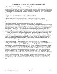
PTMC Interface Configurations<br />
Interface 0 1 2 3 4 5 6 7 >7<br />
Serial Tx/Rx x x x x x x<br />
RMII x x<br />
RMII PHY Management I/F x x<br />
10/100/1000 Ethernet MDI Ports 2 2<br />
UTOPIA I/II (8-bit) x x x x<br />
UTOPIA II (8/16-bit) x x<br />
POS-PHY<br />
x<br />
Local CT (20 bit) x x<br />
Extended Local CT (32 bit)<br />
x<br />
USER IO Pins<br />
64 66 6 0 40 4 64<br />
32-bit PCI x x x x x x x x<br />
64-bit PCI<br />
x<br />
JTAG x x x x x x x x<br />
SMB x x x x x x x x<br />
RESERVED<br />
Note: In Configurations 2 and 3, two of the USER IO pins are located on Jn3, and are identified<br />
as USER1Z and USER2Z.<br />
RESERVED<br />
FOR INFORMATION ONLY;<br />
DO NOT ATTEMPT TO DESIGN FROM THIS DOCUMENT
<strong>PICMG</strong> ® <strong>2.15</strong> Revision 1.0 SHORT FORM Specification<br />
Relationship of Existing Standards and PTMC<br />
Editorial corrections to the base <strong>PICMG</strong> <strong>2.15</strong> Release 1.0 document are also included in this ECN to<br />
properly identify references to the Local CT bus and H.110 backplane CT bus signals. These changes do<br />
not affect the functionality defined in the base specification.<br />
Justification<br />
The new mezzanine connector signal configurations introduced with this ECN define PTMCs that are<br />
capable of managing larger traffic capacities (672 equivalent voice connections and above) than the<br />
current PTMC mezzanine configurations permit. These higher traffic capacities are enabled with current<br />
generation link termination and traffic processing silicon. PTMCs implementing these new buses will be<br />
capable of implementing voice traffic transcoding operations among the following traffic protocols:<br />
- Voice over IP (VoIP) traffic carried on 100Base-TX or 1000Base-T Ethernet links, either at a<br />
front panel link on the mezzanine board or across the mezzanine / carrier connectors;<br />
- Voice over ATM traffic carried in either AAL1 or AAL2 cells on external transmission links at<br />
the front panel of the mezzanine board or on a Utopia 2 bus across the mezzanine / carrier<br />
connectors;<br />
- TDM voice traffic carried on either external TDM facilities at mezzanine board front panel<br />
connectors or on an extended Local CT bus at the mezzanine / carrier connectors.<br />
FOR INFORMATION ONLY;<br />
DO NOT ATTEMPT TO DESIGN FROM THIS DOCUMENT
<strong>PICMG</strong> ® <strong>2.15</strong> Revision 1.0 SHORT FORM Specification<br />
INTRODUCTION<br />
The PCI <strong>Telecom</strong> <strong>Mezzanine</strong> <strong>Card</strong> (PTMC) is based on the four connector standard PCI<br />
<strong>Mezzanine</strong> <strong>Card</strong> (PMC). The PTMC provides all of the traditional PMC 32-bit PCI signals on<br />
the Pn1 and Pn2 connectors and specifies the use of industry standard telecom interfaces on Pn3<br />
and Pn4. In addition, interoperability with 64-bit PCI is provided as a dedicated configuration<br />
type. PTMC leverages the success, form factor, and functionality of the PMC series of<br />
peripheral mezzanine cards, but is not a replacement for PMC. It will coexist with PMC and<br />
support four popular industry standard telecom bus interfaces. PTMC brings new definition and<br />
flexibility to the world of slim modular mezzanine cards for PCI, <strong>CompactPCI</strong>, and VME.<br />
Objectives of the PCI <strong>Telecom</strong> <strong>Mezzanine</strong>/Carrier <strong>Card</strong> Specification<br />
The objective of the PTMC is to provide an industry standard from which designers,<br />
manufacturers, and integrators will have a common platform for implementing a variety of<br />
telecommunications hardware or specialized voice and data applications.<br />
PTMC represents a leap in standardization for hosts and carriers with the capability for<br />
delivering modular multi-function resources, through universal mezzanine cards that offer line<br />
interface and/or co-processor functionality. <strong>Card</strong> vendors and developers will no longer have to<br />
choose between competing hardware architectures to support standard telephony interfaces.<br />
Instead, they will simply select PTMC modules with options based on the applications and<br />
functionality that they wish to implement.<br />
Design Goals<br />
• Maximize Printed Circuit Board (PCB) space available for circuitry.<br />
• Maintain Full Interoperable Compatibility (FIC) between PCI <strong>Telecom</strong> Carrier <strong>Card</strong>s<br />
(PTCC) and PMC mezzanine cards (32-bit and 64-bit).<br />
• Maintain Partial Interoperable Compatibility (PIC) between PTMC mezzanine cards and<br />
PMC carrier cards that do not utilize Pn3/Jn3.<br />
• Maintain Non-Invasive Compatibility (NIC) between PTMC modules and PMC carrier<br />
cards that utilize Pn3/Jn3 to implement the 64-bit PCI bus extension (PCC64).<br />
• Support multiple configurations of PTMC and PTCC modules and automatically sense<br />
compatibility in hardware.<br />
• Support user-defined Input/Output (I/O) for some configurations.<br />
• Specify nothing that precludes Network Equipment Building Systems (NEBS)<br />
compliance.<br />
• Any PTMC application is correctly mapped to exactly one configuration and the rules for<br />
making this mapping are clear.<br />
PTMC is not a replacement for PMC – it is a specialized type of PMC. A PTMC module is<br />
intended to interoperate primarily with special PCI <strong>Telecom</strong> Carrier <strong>Card</strong>s (PTCC), although<br />
some interoperability with PCI Carrier <strong>Card</strong>s (PCC) is supported.<br />
FOR INFORMATION ONLY;<br />
DO NOT ATTEMPT TO DESIGN FROM THIS DOCUMENT
<strong>PICMG</strong> ® <strong>2.15</strong> Revision 1.0 SHORT FORM Specification<br />
A deliberate effort was made to limit the PTMC to no more than four connectors to maximize<br />
utilization of card surface area for IC and component placement. PTMC implements connector<br />
configurations on two 64-pin connectors (Pn1/Jn1and Pn2/Jn2). These are identical to PMC<br />
mezzanine card standards. Pn3/Jn3 and Pn4/Jn4 are implemented with identical 64-pin<br />
connectors. Pn3/Jn3 is utilized to provide telecom specific functionality or 64-bit PCI bus<br />
extensions. Pn4/Jn4 is utilized to provide telecom specific functionality or user-defined I/O.<br />
Backwards compatibility with PMC cards compliant to IEEE 1386.1 and IEEE 1386 is<br />
maintained mechanically to allow a PTCC to operate with PMC mezzanine cards via Pn1/Jn1,<br />
Pn2/Jn2, Pn3/Jn3, and Pn4/Jn4. Backwards compatibility with PMC cards compliant to IEEE<br />
1386.1 is maintained electrically to allow a PTCC to operate with PMC mezzanine cards via<br />
Pn1/Jn1 and Pn2/Jn2.<br />
Ground signal assignments on Pn3/Jn3 have been allocated identically to the 64-bit PCI bus<br />
specification to eliminate conflict with carriers supporting 64-bit access. PCI data accesses of 64<br />
bits are supported on the mezzanine card as a dedicated PTMC configuration. Other PTMC<br />
configurations are non-invasive to the carrier card such that 64-bit operation can function on the<br />
carrier while the mezzanine card is mated. The complete <strong>2.15</strong> specification describes the level of<br />
interoperability for a variety of configurations.<br />
A PCI <strong>Telecom</strong> IDentification (PTID) mechanism is specified for PTMC that allows a<br />
mezzanine card to advertise its configuration and sense the carrier’s assertion of compatibility.<br />
The complete <strong>2.15</strong> specification provides a thorough discussion of the interoperability of specific<br />
mezzanine and carrier combinations.<br />
The PTID mechanism is implemented to inherently allow a mezzanine card to sense that it has<br />
been mated to a PMC carrier card. <strong>Mezzanine</strong> cards will electrically isolate their Pn3/Jn3 and<br />
Pn4/Jn4 PTMC specified signals until the carrier determines that an interoperable configuration<br />
has occurred. The complete <strong>2.15</strong> specification describes the PTID configuration mechanism and<br />
its use in determining interoperability between carrier and mezzanine cards.<br />
User-defined I/O has been maintained on Pn4/Jn4, for some configurations, in order to support<br />
custom connectivity. The definition of all user-defined I/O is outside the scope of this<br />
specification. Therefore, user-defined I/O on Pn4/Jn4 need not follow PTMC specified signal<br />
isolation requirements. User-defined I/O on Pn3/Jn3 must follow PTMC specified signal<br />
isolation requirements for compatibility with 64-bit PCI signaling.<br />
Some PTMC applications can function equally well with more than one configuration. This<br />
specification requires that a PTMC advertise a single configuration type. The complete <strong>2.15</strong><br />
specification describes how to correctly choose a single PTMC configuration type.<br />
FOR INFORMATION ONLY;<br />
DO NOT ATTEMPT TO DESIGN FROM THIS DOCUMENT
<strong>PICMG</strong> ® <strong>2.15</strong> Revision 1.0 SHORT FORM Specification<br />
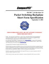
Interface<br />
PTMC Interface Configurations<br />
Serial Tx/Rx x x x x<br />
RMII x x<br />
RMII PHY Management I/F x x<br />
UTOPIA I/II (8-bit) x x x<br />
Configuration<br />
0 1 2 3 4 5 6 7 >7<br />
RESERVED<br />
UTOPIA II (8/16-bit)<br />
x<br />
POS-PHY<br />
x<br />
Local CT x x<br />
USER IO<br />
64 66 6 0<br />
64<br />
32-bit PCI x x x x x x x x<br />
64-bit PCI<br />
x<br />
JTAG x x x x x x x x<br />
SMB x x x x x x x x<br />
RESERVED<br />
RESERVED<br />
RESERVED<br />
OVERVIEW<br />
PCI and <strong>CompactPCI</strong> cards inter-communicate (within their respective systems) across a<br />
common backplane via connections implemented with multiple high-density connector plugs and<br />
jacks. Each slot’s high-density connector set allows wide data and address busses to be<br />
implemented for supporting high-bandwidth data transfers.<br />
Further demands for bandwidth can be addressed by subdividing the system architecture.<br />
Processes that do not require connectivity to every slot can be isolated to dedicated secondary<br />
data busses with a single bridge to the primary bus. This hierarchical approach requires bridge<br />
components and enables the use of more processors to improve total system bandwidth. The<br />
need for large amounts of circuitry within a single slot is often addressed with one or more<br />
mezzanine cards that communicate with a carrier card. Only the carrier card need communicate<br />
with the backplane, thus allowing the mezzanine/carrier combination to utilize a single<br />
backplane slot. PTMC supports this approach for several popular telecommunication interfaces.<br />
The PTMC specification utilizes industry standards for mezzanine cards and for<br />
telecommunication busses. This standardizes the mechanical, electrical and functional aspects of<br />
mezzanine-carrier interoperability in a telecommunications system. Restrictions and relaxations<br />
of implementation requirements for these specifications are provided.<br />
FOR INFORMATION ONLY;<br />
DO NOT ATTEMPT TO DESIGN FROM THIS DOCUMENT
<strong>PICMG</strong> ® <strong>2.15</strong> Revision 1.0 SHORT FORM Specification<br />
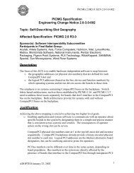
Existing Standards<br />
The chart below shows the parent/child relationships among specifications. The PCI <strong>Telecom</strong><br />
<strong>Mezzanine</strong>/Carrier <strong>Card</strong> Specification (PTMC) standardizes the mechanical and physical aspects<br />
of the mezzanine card and its connection to a carrier card. Individual PTMC implementations<br />
make use of the electrical and functional features of several popular telecommunication<br />
standards.<br />
<strong>PICMG</strong> <strong>2.15</strong><br />
PTMC<br />
IEEE 1386.1<br />
PMC<br />
H.110<br />
ECTF<br />
UTOPIA<br />
Level 2<br />
POS-PHY<br />
RMII<br />
SMBus<br />
IEEE 1386<br />
CMC<br />
UTOPIA<br />
Level 1<br />
IEEE 802.3<br />
I2C<br />
PCI<br />
Relationship of Existing Standards and PTMC<br />
###<br />
FOR INFORMATION ONLY;<br />
DO NOT ATTEMPT TO DESIGN FROM THIS DOCUMENT