Ready Welder II Operation Manual. - Pirate4x4.Com
Ready Welder II Operation Manual. - Pirate4x4.Com
Ready Welder II Operation Manual. - Pirate4x4.Com
You also want an ePaper? Increase the reach of your titles
YUMPU automatically turns print PDFs into web optimized ePapers that Google loves.
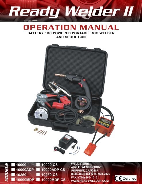
<strong>Ready</strong> <strong>Welder</strong> <strong>II</strong><br />
OPERATION MANUAL<br />
BATTERY / DC POWERED PORTABLE MIG WELDER<br />
AND SPOOL GUN<br />
MODELS<br />
10000<br />
10000ADP<br />
10250<br />
10000MDP<br />
10000-CS<br />
10000ADP-CS<br />
10250-CS<br />
10000MDP-CS<br />
WELDSTONE<br />
4769 E. WESLEY DRIVE<br />
ANAHEIM, CA 92807<br />
(800) 465-9184 (714) 970-2076<br />
FAX: (714) 463-1013<br />
WWW.READYWELDER.COM<br />
Certified
READY WELDER <strong>II</strong><br />
TABLE OF CONTENTS<br />
Warranty Information . . . . . . . . . . . . . . . . . . . . . . . . . . . . . . . . . . . 1<br />
Safety . . . . . . . . . . . . . . . . . . . . . . . . . . . . . . . . . . . . . . . . . . . . . 1-2<br />
Frequently Asked Questions . . . . . . . . . . . . . . . . . . . . . . . . . . . . . 3<br />
Important Operating Tips . . . . . . . . . . . . . . . . . . . . . . . . . . . . . . . 4<br />
Thin Metal Welding . . . . . . . . . . . . . . . . . . . . . . . . . . . . . . . . . . . . 5<br />
Wire Spool Installation . . . . . . . . . . . . . . . . . . . . . . . . . . . . . . . . . 5<br />
Loading the <strong>Ready</strong> <strong>Welder</strong> <strong>II</strong> . . . . . . . . . . . . . . . . . . . . . . . . . . . . 6<br />
Welding Aluminum . . . . . . . . . . . . . . . . . . . . . . . . . . . . . . . . . . . . 7<br />
<strong>Operation</strong> . . . . . . . . . . . . . . . . . . . . . . . . . . . . . . . . . . . . . . . . . . . 8<br />
Connecting Your RW-<strong>II</strong> . . . . . . . . . . . . . . . . . . . . . . . . . . . . 8-10<br />
MIG Machine As The RW-<strong>II</strong> Power Source . . . . . . . . . . . . . . . . . . . 11<br />
Diagrams For Battery Connections . . . . . . . . . . . . . . . . . . . . . . . 11-12<br />
Diagrams For Connection to CV MIG Machine . . . . . . . . . . . . . . . 13-14<br />
Diagrams For Connection to CC Stick <strong>Welder</strong> . . . . . . . . . . . . . . . 14<br />
Routine Maintenance . . . . . . . . . . . . . . . . . . . . . . . . . . . . . . . 15<br />
Recommended Periodic Mantenance . . . . . . . . . . . . . . . . . . . . . . 15<br />
Troubleshooting . . . . . . . . . . . . . . . . . . . . . . . . . . . . . . . . . . . 16<br />
Applications Table . . . . . . . . . . . . . . . . . . . . . . . . . . . . . . . . . . . 17<br />
Assembly Diagram . . . . . . . . . . . . . . . . . . . . . . . . . . . Back Cover<br />
FOR ADDITIONAL ASSISTANCE, CONTACT US AT (800) 465-9184
WARRANTY INFORMATION<br />
This Limited Warranty supercedes all previous RW-<strong>II</strong> warranties and is exclusive, with no other guarantees or warranties<br />
expressed or implied.<br />
Your RW-<strong>II</strong> is warranted to be free from defects in material and workmanship for a period of one year from the date<br />
of the original purchase (proof of purchase required). This warranty covers only failures due to defects in material or<br />
workmanship which occurs during normal use and does not cover damage which occurs in shipment or failures which<br />
result from accident, misuse, abuse, neglect, mishandling, misapplication, alteration, or modification of the product,<br />
or damage that is attributable to acts of God.<br />
The warrantor shall not be responsible for any incidental or consequential damages resulting from the use of this<br />
product, or arising out of any breach of this warranty. All express and implied warranties, including the warranties or<br />
mechantability and fitness for a particular purpose, are limited to the applicable warranty period set forth above.<br />
IMPORTANT NOTICE: Certain states do not allow the exclusion or limitation of incidental or consequential damages<br />
or limitations to the length of an implied warranty, therefore the above exclusions or limitations may not apply<br />
to you. This warranty gives you specific legal rights, and you may also have other rights, which vary from state to<br />
state.<br />
SAFETY<br />
READ THESE WARNINGS - PROTECT YOURSELF AND OTHERS<br />
BE AWARE, SERIOUS INJURY OR DEATH MAY RESULT if welding or cutting equipment is not properly<br />
installed, used, and maintained. Misuse of this equipment and other practices can be both hazardous and dangerous to<br />
the operator and any persons in the general work area. The operator, supervisor, and helper must read and understand<br />
the following safety warnings and instructions before installing or using any welding or cutting equipment.<br />
The welding and/or cutting process is used in many potentially dangerous and hazardous conditions. In environments<br />
such as elevated heights, areas of limited ventilation, close quarters, around water, uncertain power sources, in hostile<br />
environments, etc., it is important that the operators are aware of the dangers and limitations associated with working<br />
in these types of conditions. Only properly trained and experienced operator(s) trained in safe practices for the<br />
environments in which they are expected to work and are under competent supervision should use this welder. It is<br />
essential that the operator, supervisor, and others in the work areas are aware of the dangers of the welding or cutting<br />
process. Training and supervision are both important and necessary for a safe work place. Please keep these instructions<br />
for future use and reference.<br />
BE AWARE, THE FOAM IN THE RW-<strong>II</strong> CASE IS FLAMMABLE<br />
Make sure the case is a sufficient distance from welding and cutting activity and is closed to avoid sparks, slag, or<br />
any hot material from coming in contact with the foam.<br />
ELECTRIC SHOCK CAN CAUSE INJURY OR DEATH<br />
Install and maintain equipment in accordance with the National Electric Code NFPA 70 and local codes. Do not service<br />
or repair equipment with power on or batteries connected. Do not operate equipment with protective insulators<br />
or covers removed. Service or repair to equipment must be done by qualified and/or trained personnel only.<br />
Operator should not and must not contact electrically live parts. Do Not touch electrode with bare skin and electrical<br />
ground at the same time. Always wear dry welding gloves in good condition. Be aware aluminized protective<br />
clothing can become part of the electrical path. Keep oxygen cylinders, chains, wire ropes, cranes, hoists, and elevators<br />
away from any part of the electrical path. All ground connections must be checked periodically to determine that<br />
they are mechanically strong and electrically adequate for the required current. When welding is to be suspended for<br />
any sustained period of time, such as during lunch or overnight, the READY WELDER <strong>II</strong> should be disconnected<br />
from its arc current power source when not in use. Never immerse MIG guns, electrode holders, TIG torches,<br />
plasma torches, or electrodes in water.<br />
1
SAFETY (continued)<br />
BE AWARE, ARC RAYS, HOT SLAG AND SPARKS CAN AND DO CAUSE INJURIES TO EYES<br />
AND SKIN<br />
The welding and/or cutting processes produce extreme localized heat and strong ultraviolet rays. Never attempt to<br />
weld and/or cut without proper welding equipment, including, but not limited to, a welding helmet with the proper<br />
lens, which complies with federal guide lines. A number 12 to 14 shade filter lens on the helmet provides the best<br />
protection against arc radiation . Please note that in a confined area prevent the reflected arc rays from entering around<br />
the helmet. It is important to make sure others are protected from arc rays and sparks. Approved shielding curtains<br />
and/or appropriate goggles should be used by all persons working in the close vicinity of the welding area to provide<br />
protection to others in the surrounding area and operators of nearby equipment. Skin should and must also be protected<br />
from arc rays, heat and molten metal. The operator must always wear protective gloves and clothing which<br />
will not allow skin to become exposed. All clothing pockets should be closed and cuffs sewn shut. Leather aprons,<br />
sleeves, leggings, etc. should and must be worn for out-of-position welding and/o r cutting. High top work shoes<br />
provide adequate protection from foot burns; for added protection, use leather spats. Flammable hair products should<br />
not be used when welding and/or cutting. Where the work permits, the operator should be enclosed in an individual<br />
booth painted with a finish of low reflectivity such as zinc oxide, an important factor for absorbing ultraviolet radiation,<br />
and lamp black, or shall be enclosed with non-combustible screens similarly painted.<br />
BE AWARE, WELDING SPARKS CAN AND DO CAUSE FIRES AND EXPLOSIONS<br />
Causes of fire and explosions are: combustibles reached by the arc, flame, flying sparks, hot slag or heated materials.<br />
Remove combustible materials and items from the work area and/or provide a fire watch. Avoid oily or greasy<br />
clothing as a spark may ignite them. It is necessary and required that the operator have a fire extinguisher nearby and<br />
have knowledge and training in it’s use. Be aware and alert to the danger of conduction or radiation. For example , if<br />
welding and/or cutting is to be done on a metal wall, partition, ceiling or roof, precautions must be taken to prevent<br />
ignition of combustibles on the other side. Do not weld and/or cut containers that have held combustibles. All hollow<br />
spaces, cavities and containers should be and must be vented prior to welding and/or cutting to permit the escape of<br />
air or gases. Purging with inert gas is recommended. Use only inert gases or inert gas mixes as required by the process.<br />
Use of combustible compressed gases can cause explosions resulting in personal injury or death. Arcing against<br />
any compressed gases can cause explosions resulting in personal injury or death.<br />
SAFETY AND OPERATION REFERENCES<br />
1. Code of Federal Regulations, (OSHA) Section 29 Part 1910.95, 132-134, 251-254 and 1000. U.S. Government<br />
Printing Office, Washington, D.C. 20402<br />
2. ANSI Z49.1 “Safety in Welding and Cutting”<br />
3. ANSI Z87.1 “Practice of Occupational and Educational Eye and Face Protection”<br />
4. ANSI Z88.2 “Standard Practice for Respiratory Protection”, American National Standard Institute, 1430 Broad<br />
way, New York, NY 10018<br />
5. AWS F4. 1 “Recommended Safe Practices for Welding and Cutting Containers”, The American Welding Society,<br />
550 NW Lejeune Road, P.O. Box 351040, Miami, FL 33135<br />
6. NFPA 51B “Fire Prevention in Cutting and Welding Processes”<br />
7. NFPA-7 “National Electrical Code “National Fire Protection Association, Battery Park, Quincy, MA 02269<br />
8. CSA Standard W117.2 “Safety in Welding, Cutting and Allied Processes” Canadian Standards Association, 178<br />
Rexdale, Ontario, Canada M9W 1R3<br />
22
FREQUENTLY ASKED QUESTIONS<br />
Below you will find answers to the most “frequently asked questions” regarding RW-<strong>II</strong>, the DC Powered MIG <strong>Welder</strong><br />
/ Spool Gun. If you have any additional questions, call us at (800) 935-3644 between 8 AM and 5 PM PST on weekdays.We<br />
hope this information will help you to obtain the highest level of satisfaction from your RW-<strong>II</strong>.<br />
1. How long of welding duration time will I get out of a pair of batteries before I<br />
will need to recharge them? Many factors will determine the length of acceptable quality welding<br />
duration time, with the primary factors being the the type and size of batteries used and the type of welding being<br />
performed. The thicker the metal being welded the greater the amperage draw will need to be to obtain satisfactory<br />
results,which will drain the batteries faster. The size and amp hour ratings of the batteries used will determine the<br />
total amount of power available and thus the welding time available, We recommend a deep cycle gel cell battery,<br />
like Optima Batteries offers, or at least a group 31 marine deep cycle battery as a power source for the <strong>Ready</strong><br />
<strong>Welder</strong> <strong>II</strong>. A fully charged pair of these batteries will normally yield a minimum duration of about 45 minutes when<br />
welding 1/2” steel or 3/4” aluminum @ approximately 175 amps, while lighter duty welding operations on thinner<br />
metal can offer a duration time of 4 hours or more. Please see the operating guidelines in your Owner’s <strong>Manual</strong> for<br />
more battery discussion.<br />
2. What type of batteries and charger should I buy, and what type of maintenence<br />
do I need to perform on the batteries? We highly suggest the purchase and investment of good<br />
quality 12DCV deep-cycle marine or RV batteries, ranging from group 24 to group 31, which is our preference. Our<br />
recommendation is Optima Batteries, they have a few deep cycle options to choose from. Their gel cell batteries will<br />
give you reliable power and a longer life. If you get one with vertical posts capped with wing-nuts, you will have easy<br />
power connections to the RW-<strong>II</strong>. Regular auto batteries and other batteries not designed for deep cycle discharging<br />
and recharging will have a shorter life span if drawn too low too many times, for occasional or recreational welding<br />
this shouldn’t be a problem. For home use, a 10 amp overnight charging will work well. Maintenance of batteries<br />
should be according to manufacturer’s instructions.<br />
3. Does the trigger control power to the tip? Depends on which model you are speaking of. If it is<br />
a model with a “-CS” at the end of the model number, then the answer is YES, IT DOES. The cold switch upgrade<br />
includes a solenoid system integrated into the cable of the gun near the quick disconnects. This solenoid system is<br />
designed as a safety switch only, and does not affect any other function of the RW-<strong>II</strong>. On the non-CS models, the<br />
trigger controls wire feed (on-off) and gas flow, as the -CS models, but does not control power feeding to the tip. The<br />
tip is live whenever the RW-<strong>II</strong> is connected to power source. The red plastic connectors in the RW-<strong>II</strong> power cable are<br />
designed to be easily disconnected to de-power the welder between uses without having to disconnect the cables at<br />
the power source.<br />
4. Does the wire feed speed control knob adjest the amerage level fed to the electrode?<br />
The wire feed speed control knob indirectly affects amperage based upon the speed and physical volume of<br />
wire being fed to the bead. The amount of wire fed to the bead is directly proportional to the ultimate amperage level<br />
delivered to the weld . The diameter of the feed wire will also affect the total amperage level delivered to the welding<br />
bead. The larger the wire the hotter it will bum as with the faster the feed rate the hotter the weld.<br />
5. I’ve got two 12 volt batteries under the hood of my vehicle. Can I hook up the<br />
RW-<strong>II</strong> to these with the motor running and battery cables still connected? No, it is<br />
not recommended as batteries are normally wired in 12V parallel for these applications (except 24V equipment) and<br />
the RW-<strong>II</strong> prefers a minimum of 18V for welding metal thicker than thin sheet metal, which means the two batteries<br />
must be wired in series to yield 24V. Leaving the batteries connected to the vehicle’s electrical system while you’re<br />
operating a RW-<strong>II</strong> may cause severe damage to the vehicle’s electrical components. Many auto parts stores sell<br />
“quick disconnect” battery terminals which come in handy for these types of situations. Please isolate the batteries<br />
electrically from the vehicle when welding, and especially when welding on the vehicle itself using flux-cored wire,<br />
as this operation uses positive ground.<br />
6. Can I connect the RW-<strong>II</strong> to my Arc or MIG <strong>Welder</strong> to use a “spool gun” attachment?<br />
Some RW-<strong>II</strong> models include an AC/DC power supply to power the circuitry of the gun. It is only required<br />
when connected to CC/stick welders and was specifically designed for these types of applications. However, it is recommended<br />
for use when connecting to CV MIG machines as well. While using the AC/DC power supply provided,<br />
the RW-<strong>II</strong> can safely be used with any DC output welding machines. Do not connect the RW-Il directly to constant<br />
current welding machines without the use of the AC/DC power supply. The power supply must be connected in<br />
the same polarity as the arc current. The use of the power supply is not mandatory when connecting to CV<br />
machines with output ranging from 18V to 40V DC, or batteries.<br />
3
IMPORTANT OPERATING TIPS<br />
In order to obtain the best possible performance and service life from your new RW-<strong>II</strong>, we recommend that you read<br />
and practice the following operati ng tips:<br />
1. SAFETY · Never open the RW-<strong>II</strong> if it is connected to a live power source!<br />
Opening the case halves while the gun is powered will likely cause severe damage to the circuit board and other<br />
parts inside the RW-<strong>II</strong>. This damage will not be covered by the warranty Also, never leave the power connected to<br />
the RW-<strong>II</strong> when you are not actually welding as the tip stays “hot” at all times, except with “-CS” models, when the<br />
power remains connected. Always disconnect the RW-Il from the power source when not in use.<br />
2. Power Connections for the RW-<strong>II</strong><br />
The RW-<strong>II</strong> comes with battery clamps which can be mounted onto the 3/8” copper lugs (hardware provided). Whenever<br />
possible it is preferable to make your power connections using the 3/8” copper lugs mounted directly to the<br />
battery terminals. Many deep-cycle batteries come with additional threaded post terminals, with wing-nuts on them,<br />
which are ideal for making these connections. The battery clamps are convenient to use but may restrict current flow<br />
and should therefore only be used when use of the 3/8” lugs is not feasible. Always securely attach the copper lug(s)<br />
to appropriate connection points directly on the welding machine itself if possible. Never connect the RW-<strong>II</strong> to AC<br />
Output Terminals on arc welding machines.<br />
3. Battery Selection<br />
Battery selection is a crucial part of successful RW-<strong>II</strong> operation. The size and power ratings of the batteries selected<br />
will have a great effect on the duration of welding time and the depth of penetration possible. For welding metal 1/8”<br />
and thicker, the larger the batteries the better. Deep cycle marine batteries are recommended, with threaded tip terminal<br />
posts topped with wing-nuts, in group sizes of 24D to 31D. Gel-Cell batteries from Optima work extremely well,<br />
but can require a special charger. Keep your batteries charged over 80% between uses to extend their life-span. Thin<br />
metal in general, and thin aluminum in particular, requires much lower amperage levels to be welded successfully<br />
than thicker metals. Sometimes the use of a single 12 volt battery with .030”-035” aluminum wire , and the proper gas<br />
mixture, will weld thin aluminum sheet. Normally the use of 18 volts, from connecting 12 volt and 6 volt batteries<br />
together in series, are necessary to weld thin steel, aluminum or stainless steel. Thinner wire conducts less electricity,<br />
so it is helpful to use thinner wire (.023”) on thin metal and thicker wire (up to .040”) when welding thicker metal.<br />
When using 12 volts the use of thicker wire may be helpful as it allows more current to flow at the lower voltage .<br />
4. Clean Metal Surfaces<br />
The metal surfaces to be welded together should be clean and free from any “mill scale” deposits found on most steel<br />
products as they come from the foundry. Grinding the surfaces to be welded down to shiny bare metal will greatly improve<br />
the strength and penetration of the weld. Because MIG welding is an electrical process, any action taken which<br />
improves the conductivity of the metal being welded will improve the final results. This also applies to the surface<br />
to which the large “grounding clamp” is connected to as well. Make sure the ground clamp is attached to clean, bare<br />
metal on the piece being welded. Remember, the cleaner the surfaces welded, the stronger the weld.<br />
5. The “RW-<strong>II</strong> Applications Table”<br />
This manual contains the “RW-<strong>II</strong> Applications” Chart (page 21). Successful welding with the RW-<strong>II</strong> can be achieved<br />
if you follow the guidelines shown in this chart, especially as it directly relates to POLARITY. Flux core wire requires<br />
reverse porarity (red light) ground positive, while solid wire (all metals) requires straight polarity (green light)<br />
ground negative and the use of an appropriate gas mixture, as specified. When using the AC/DC power supply supplied<br />
with RW-<strong>II</strong>, the LED’s no longer indicate arc current polarity but simply reveal that the RW-<strong>II</strong> circuit board is<br />
being powered. The AC/DC power supply must be connected in the same polarity as the arc current. The small red<br />
pigtails included with the system will allow for the AC/DC power supply to be hooked up in reverse polarity.<br />
6. Lever Tension Spring Settings<br />
The lever tension spring adjuster selector should normally be left in the “Steel” slot for proper wire feed tension for<br />
.035” wire. Use of .023” wire may sometimes require that the selector spring be moved to the “Extra Grip” slot setting,<br />
while thicker wires may require use of the “Aluminum” slot setting. Select the firmest setting which still allows<br />
the wire to feed freely without causing the motor to bog down or the wire feed rate to be inconsistant.<br />
4
THIN METAL WELDING<br />
When attempting to weld metal thinner than 1/8” with the RW-<strong>II</strong>, we recommend the following guidelines.<br />
POWER CONTROL GUIDELINES<br />
1. Determine the Minimum Voltage You Can Use In The Given Situation. Some thin sheet metal can be welded<br />
with 12VDC from a single battery. Two 6 volt deep cycle batteries connected in series can yield up to approximately<br />
15VDC. The use of 18 volts DC, obtained by connecting a 6 volt battery in series with a 12 volt battery, will<br />
provide enough arc current to weld all metals with a thickness of 1/8” or less but be aware it can get hot enough to<br />
cause melt through.<br />
2. Use the Smallest Diameter of Feed Wire Available of the Type Desired. The smaller the diameter of wire the<br />
less current it can conduct, therefore use the smallest diameter feed wire you can in any given application to cool<br />
down the bead to reduce melt-through. Solid steel, stainless and Aluminum wires come in .023” diameter and will<br />
require the use of gas. Flux core wire comes in .030”, typically as a minimum.<br />
3. Use Increased Wire “Stick-Out’’ Length to Cool the Bead. The greater the distance from the end of the contact<br />
tip to the bead, the greater the resistance faced by the arc current. Increasing wire “stick-out” works best with<br />
flux cored wire since you will not be concerned about keeping any shielding gas focused on the bead area.<br />
4. “Stitch Welding” Mode. The use of this mode of welding should allow you to successfully weld thin sheet<br />
metal at a 24 volt power level without melt-through problems. By producing a series of small, cooler beads, rather<br />
than a continuous bead, the stitch mode process prevents the bead area from getting hot enough to melt the surrounding<br />
metal. To use this process, tum the RW-<strong>II</strong>’s wire feed speed control knob to the “off” position and then<br />
slowly advance it until the electrode wire just starts to feed slowly out of the contact tip. Release the trigger and cut<br />
off the excess wire which has been fed out. Aim the RW-<strong>II</strong> at the thin metal you wish to weld and pull the trigger<br />
while allowing for the maximum acceptable amount of wire “stick-out”. Keep the RW-<strong>II</strong>’s trigger pulled during the<br />
entire stitch mode welding process. When the feed wire makes contact and creates a small bead, the feed wire will<br />
momentarily melt back to the point that the arc is broken. The feed wire will feed out to the point that another bead<br />
is started where the previous bead ended. Repeat this process of connecting small, sequential beads until the job is<br />
complete. By using the maximum wire “stick-out” you can reduce the likelihood of wire “burn-back” clogging the<br />
contact tip.<br />
5. Increased External Resistance. This will lower the output and can be done in several different ways such as<br />
longer cable, smaller cable or by attaching a piece of chain to the work piece and adjusting the ground clamp up or<br />
down the chain, be aware that increased resistance causes greater heat!<br />
WIRE SPOOL INSTALLATION<br />
The <strong>Ready</strong> <strong>Welder</strong> system is shipped virtually ready-to-use as its name implies. The only preparation required is to<br />
load the RW-<strong>II</strong> welding gun with a wire spool. Wire cutters, and a flat head screw driver are the only tools needed.<br />
Wire Loading Guidelines<br />
Before opening the RW-<strong>II</strong> case halves to load a wire spool, be sure to disconnect the gun from any “live” power<br />
sources, including the AC/DC power supply if so equipped. The RW-<strong>II</strong> comes equipped with quick disconnects in its<br />
power cord to make this process quick and easy without the need to disconnect the power leads at the batteries or<br />
welding machine. Failure to follow this rule can lead to personal injury and cause could cause damage to the RW-<strong>II</strong><br />
gun which will not be covered under the warranty as this would constitute user negligence. Before loading any wire<br />
spool be sure that the wire selected is suitable for the task at hand. Please refer to the chart on page 21.<br />
Control Functions<br />
The RW-<strong>II</strong>’s primary user controls consist of a trigger and a wire feed speed control knob. There are also LED indicator<br />
lights just ahead of the wire feed speed control knob which indicate arc current polarity with battery power hookups<br />
(and with machine hook-ups when no AC/DC power supply is being utilized). When using the RW-<strong>II</strong> supplied<br />
AC/DC power supply to power the RW-<strong>II</strong> circuit board and motor, the LED light will indicate only that the AC/DC<br />
power supply is powered and is properly connected to the RW-<strong>II</strong>. Arc current polarity is NOT indicated by the LED’s<br />
when the AC/DC power supply is being utilized. The power supply must be connected in the same polarity as the<br />
power source. The small red pigtails included with the system will allow for the AC/DC power supply to be hooked<br />
up in reverse polarity.<br />
5
LOADING THE READY WELDER <strong>II</strong><br />
1<br />
2<br />
Remove the T-Bolt handle (turn counter clockwise).<br />
3<br />
Lift top half of case from spool end first to allow the<br />
retainer clip securing the case halves at the tip end to<br />
disengage. Remove nozzle and insulator, then remove<br />
gas diffuser and tip; this will make loading the wire<br />
much easier.<br />
4<br />
Select wire to be used. Unroll a few inches of wire,<br />
making sure to hold the coil firmly to prevent “bird<br />
nesting”. Clip off the end of the wire, leaving 3 to 4<br />
inches of straight wire.<br />
5<br />
Place the spool in the housing of the gun, being sure to<br />
hold the wire firmly. Press the red tension lever and insert<br />
the wire between the rollers into the slot. Be sure<br />
to feed the wire parallel to the flat surface of the brass<br />
bracket. The wire should feed quickly and easily.<br />
CAUTION: ALWAYS DISCONNECT THE<br />
GUN FROM THE POWER SOURCE AND<br />
LET IT COOL DOWN BEFORE OPENING<br />
THE CASE FOR ANY REASON!<br />
Install the gas diffuser and tip. Then, reinstall the<br />
nozzle cup and insulator. This will prevent accidental<br />
arcing.<br />
CAUTION: ONCE THE WELDER IS CON-<br />
NECTED TO THE POWER SOURCE, THE<br />
CIRCUITRY IS LIVE, AS WELL AS THE GUN<br />
TIP ON NON-CS MODELS. BE VERY CARE-<br />
FUL NOT TO ACCIDENTALLY GROUND TIP<br />
TO ANYTHING WHEN THE WELDER IS<br />
CONNECTED!<br />
6
WELDING ALUMINUM WITH THE RW-<strong>II</strong><br />
GENERAL POINTS FOR THE READY WELDER <strong>II</strong><br />
When welding aluminum, be sure to use a contact tip which is .005 larger than the wire diameter itself, and extend the<br />
nozzle out approximately 3/8”, this helps reduce burn back (i.e. melting the wire in the tip). As aluminum conducts<br />
heat so rapidly, some users find it preferable to increase the wire speed and move more quickly across the metal being<br />
welded, especially on thin aluminum of 1/8” and less. Please consult the chart on page 21.<br />
Preheating aluminum over 1/4” to approximately 250 O F., is a widely recognized practice and helps on the start of the<br />
bead while increasing the penetration. Using a heat sink steel plate on the back side of aluminum can help prevent<br />
burn through. Please note: When welding, thin aluminum wire will help to reduce the voltage and amperage. See thin<br />
metal guidelines on page 5. When welding on 1/8” thick aluminum or less, the travel rate must be faster than on steel<br />
and movement must be similar to drawing a line on a piece of paper. When the wire speed is adjusted correctly there<br />
should be no spatter and the weld process should be very quiet, similar to the sound of a gas leak. HINT: The proper<br />
travel is to push with aluminum usually right to left if you’re right handed and left to right if you’re left handed.<br />
BIRD NESTING<br />
The RW-<strong>II</strong> has been used for many years with great success. However, we do know that some users are more successful<br />
than others. Bird nesting may occur when wire stick out makes contact with grounded surface. Very important to<br />
remember that the wire is electrically hot when there is power to the RW-<strong>II</strong> unit, unless equipped with the CS<br />
option. This means that if the aluminum wire extending out of the contact tip comes in contact with the grounded<br />
work; it will burn back and weld into the contact tip. Taking this condition into consideration may eliminate some<br />
frustration and excessive use of contact tips. The following suggestions should provide information to make welding<br />
aluminum easy using the RW-<strong>II</strong> spool gun. As with all installations of weld wire, and especially aluminum, be sure<br />
that the <strong>Ready</strong> <strong>Welder</strong> is NOT connected to any welding power source (batteries or DC welding machines). Once the<br />
aluminum wire is installed, install the gas diffuser and contact tip, and then trim any excess wire flush to the nozzle.<br />
To avoid excessive tip replacement and arc flashing, it is important to remember to pull away from the grounded work<br />
just prior to releasing the spool gun trigger when concluding a weld.<br />
READY TO WELD WITH ALUMINUM<br />
You are now ready to establish an arc and weld aluminum. Depending on the thickness, and mass of aluminum to be<br />
welded, a slight pre heat in the area where you are going to start will help provide a uniform weld bead. Your welding<br />
position should be with a slight tilt of the spool gun into the direction of the travel; this is called the forehand<br />
technique. When you are ready to establish the arc, hold the gun nozzle about 1/4” away from the grounded work<br />
piece. Slowly depress the gun trigger to start the flow of argon shield gas. Now pull the gun trigger and establish the<br />
weld. The weld wire should burn off slightly above the grounded work piece. If excess spatter and a cracking sound<br />
are detected, slow the wire speed just slightly until it smoothes out to a quiet smooth running arc. If you are welding<br />
lighter gauge aluminum, increasing travel speeds will help avoid burning through. In some cases reducing power to<br />
18VDC, a 12 and 6 volt battery in series, will also make it easter to weld.<br />
We know that welding aluminum is not easy for the inexperienced welder, it can also be different for those welders<br />
that are not familiar with the RW-<strong>II</strong>. There are many satisfied RW-<strong>II</strong> owners doing an excellent job with welding<br />
aluminum, as it is one of it’s key features. With a little practice, you will be successful at welding aluminum. If you<br />
have any ques tions or technical assistance, just call us at (800) 935-3644 or email techsvc@readywelder.com.<br />
SETTINGS FOR WELDING ALUMINUM<br />
The suggested settings for the RW-<strong>II</strong> with batteries are as follows; Three charged 12 volt batteries in series will provide<br />
plenty of power for heavy, thick, and large aluminum welding jobs. Two 12 volt batteries in series will provide<br />
up to 275 amps for most jobs. One 12 volt and one 6 volt battery works well on 1/8” or thinner aluminum. Wire sizes<br />
.023” - .030” should be used for thinner sections and .035” - .040” is for heavier sections of aluminum.<br />
When connections are completed and you are ready to begin welding, set the spool gun speed control to 50%. Then<br />
adjust as required, remember, wire size will also have an effect on the welding current.<br />
On DC stick electrode machines; be sure that the AC/DC power supply is plugged into a 115V AC outlet and is connected<br />
to the RW-<strong>II</strong> cable assembly prior to hooking to the CC power source. Because there are a large variety of<br />
these machines, we find it important to understand that wire size and current settings need to be carefully evaluated,<br />
for example, an .023” aluminum wire may require as little as 80-100 amps, so you must make adjustments to the wire<br />
speed and machine settings to get the desired amperage.<br />
Aluminum wire size .030” usually requires a minimum of 130 amps, and the .035” wires may require a minimum<br />
of 150 amps, if possible adjust the voltage and wire speed to match the wire size being used.<br />
7
OPERATION<br />
Duty Cycle<br />
Unlike conventional welders, which are limited in how long they can weld because of heat build-up, the RWIl has .<br />
a 100% duty cycle when shielding gas is being used. The use of flux-core wire with high amperage levels will require<br />
cooling periods, however the welder can be cooled rapidly with compressed air. When operating from direct current<br />
drawn from battenes, there are no power source somponents to overheat. The system can be operated continuously<br />
for as long as the batteries can deliver power. As always be sure to leave a small gap between the back end of the<br />
nozzle and the plastic face of the gun, so heat will not be directly transfered into the plastic and cause damage to the<br />
RW-<strong>II</strong>.<br />
Using the MIG Gun<br />
RW-<strong>II</strong> can use a number of types and sizes of welding wire, some shown in the Application Chart on page 21. One<br />
of the major advantages of the RW-<strong>II</strong> is the ability to control the speed of the wire directly from the gun. Wire speeds<br />
can range from 50 inches per minute for lighter work to 900 inches per minute for heavier jobs, this speed selection<br />
is done using the RW-<strong>II</strong> speed selector knob. The Application Chart lists various metals that can be welded using the<br />
RW-<strong>II</strong>, and includes recommendations for wire, gas tips, and various system settings to be used.<br />
CONNECTING YOUR RW-<strong>II</strong><br />
BATTERIES<br />
Batteries are an excellent power source for welding, as this is pure DC power. Two 12 volt batteries connected in<br />
series will produce 24VDC, and will provide up to 275 amps of power with .040” wire, to single pass up to 1/2” plate.<br />
At 36VDC, the RW-<strong>II</strong> will pull up to 350 amps to penetrate 3/4” material. The RW<strong>II</strong> will, under the correct circumstances,<br />
make an ideal thin metal welder using 12VDC. Larger wire has less resistance 12 volts, so the RW-<strong>II</strong> should<br />
be able to weld 18 to 24 gauge metal using .035” wire. The opposite is the rule for 24 volt power, as you decrease the<br />
wire size down to .023”, this will increase the resistance to help reduce the output power. By adjusting the gas mixture<br />
and voltage, the RW-<strong>II</strong> will adjust to a spray transfer process. Deep cycle marine batteries have a longer discharge/<br />
recharge life over standard batteries. However, welding performance will be the same with either type of battery.<br />
Model 10000/10000-CS<br />
Connect two 12 volt batteries in series by connecting the positive terminal of battery #1 to the negitive terminal of<br />
battery #2. This set up provides the necessary 24 volts. For all gas shielded wires use standard polarity (green LED<br />
light). Connect the lead (gun) to the positive terminal on battery #2 and the ground to the negative terminal of battery<br />
#1. Again the green polarity light indicates proper standard polarity. For flux core, self-shielded, wire use negative<br />
polarity (red LED light) with the gun lead connected to the negative terminal of battery #1 and the ground connected<br />
to the positive terminal of battery #2. See illustration on page 12.<br />
Model 10000ADP/10000ADP-CS<br />
Connect to batteries as described above, except you will need to connect the small black wire from the jacket of the<br />
cable to the small red wire connector on the negative side of the red plug, this will then complete the circuit of the<br />
motor. See illustration on page 12.<br />
Model 10250/10250-CS<br />
This model is not shipped from the factory with a ground cable or a battery series cable. The user must supply both<br />
of these items for battery connection. Connect the batteries in series as described before, connect the RW-<strong>II</strong> lug to<br />
the open positive and the ground to the open negative. Connect the small jumper wire equipped with the mini clamp<br />
to the negative with the ground to complete the motor circuit. This set up is for welding with gas, straight polarity<br />
(green LED light). Reverse the leads for flux core wire, no gas, reverse polarity (red LED light). See illustration on<br />
page 13.<br />
8
CONNECTING YOUR RW-<strong>II</strong> (continued)<br />
DC/CV POWER SOURCE<br />
Constant Voltage (CV) MIG machines also make an excellent power source for the RW-<strong>II</strong>. The voltage control on<br />
these machines will directly affect the welding power. The wire speed will also have an effect on the power, i.e. the<br />
faster the wire feed the higher the amp draw. It is not required to use the AC/DC power supply supplied with these<br />
machines, but if the power supply is used, it must be connected in the same polarity as the arc current. The RW-<strong>II</strong> will<br />
be controled by the voltage control on the machine.<br />
Model 10000/10000-CS<br />
Connect the RW-<strong>II</strong> positive lug to the positive output stud on the machine, or you can connect to any part of the roller<br />
block, if needed. Then connect the negative lug of the RW-<strong>II</strong> to the negative post of the machine. Connect the RW-<strong>II</strong><br />
ground clamp to the work piece, and close the contactor on your machine. Some models require you to close the contactor<br />
by closing the existing MIG gun switch/trigger, this can sometimes be accomplished by jumping the contactor<br />
if the machine has a 7 or 14 pin connector on the front. Be sure to release the drive roll tension if there is wire in the<br />
machine. See illustration on page 16.<br />
Model 10000ADP/10000ADP-CS<br />
Connect as described above, except connect the small black wire from the jacket to the small red wire on the<br />
negative side of the red plastic connector. See illustration on page 16.<br />
Model 10250/10250-CS<br />
Connect the RW-<strong>II</strong> lug to the positive output on the machine or to one of the bolts on the roller block, connect the<br />
small clamp to the connector from the jacket of the RW-<strong>II</strong> and to the negative post in the machine or anywhere along<br />
the machine ground. Connect the machine ground to the work piece. Again, some machines require you to close the<br />
contactor by closing the existing MIG gun switch/trigger, this can sometimes be accomplished by jumping the contactor<br />
if the machine has a 7 or 14 pin connector on the front. Be sure to release the drive roll tension if there is wire<br />
in the machine. See illustration on page 16.<br />
DC/CV ENGINE DRIVES<br />
Model 10000/10000-CS<br />
Connect the RW-<strong>II</strong> positive lug to the positive output stud on the machine and connect the machine ground to the<br />
negitive lug of the RW-<strong>II</strong> for straight polarity. Reverse the connections for reverse polarity. Then connect the RW-<strong>II</strong><br />
ground clamp to the work piece.<br />
Model 10000ADP/10000ADP-CS<br />
Connect the same as described above except, you will need to connect the small black wire from the<br />
jacket to the small red wire on the negative side of the red connector and be sure the machine is set on constant voltage<br />
(CV).<br />
Model 10250/10250-CS<br />
Connect the RW-<strong>II</strong> lug to the positive output on the machine then connect the small clamp to the connector from<br />
the jacket of the RW<strong>II</strong> and to the negative post on the machine or anywhere along the machine ground. Connect the<br />
machine ground to the work piece . Be sure the machine is set on CV.<br />
DC/CC ENGINE DRIVES AND STICK MACHINES<br />
All stick welding machines are constant current (CC). These machines can be difficult to adjust to, at first, as the<br />
initial voltage spike causes the wire to burn back readily. However, once you have mastered the technique it should be<br />
easy to repeat. These power sources will weld aluminum and flux core wire but generally will not have the sustained<br />
voltage to run hard wire. Always start with a higher wire speed and adjust down until the arc appears to “dial in”. The<br />
machine will drop from approximately 80 volts to the mid 20 volt range after the initial arc is struck. It is imperative<br />
to use the AC/DC power supply supplied with the RW-<strong>II</strong> and it must be connected in the same polarity as the arc current.<br />
Gas welding is DC+ or ground negative (green LED light), and flux core is DC- or ground positive (red LED<br />
light). Change arc polarity as you would with a welding rod.<br />
Model 10000/10000-CS<br />
These models are not suitable for constant current machines, it can be upgraded at the factory for a fee to include<br />
the AC/DC power supply and its proper connections.<br />
9
CONNECTING YOUR RW-<strong>II</strong> (continued)<br />
Model 10000ADP/10000ADP-CS<br />
Connect the postivie RW-<strong>II</strong> lug to the stinger and the negative RW-<strong>II</strong> lug to the ground c1amp of the machine. As<br />
normal, the RW-<strong>II</strong> can also be directly connected to the positive and negative posts. It is imperative that you use the<br />
AC/DC power supply to drive the gun controls, these connections must be in the same polarity as the arc current. See<br />
illustration on page 15.<br />
Model 10250/10250-CS<br />
Connect postive RW-<strong>II</strong> lug to the stinger or directly to the positive output on the machine. It is imperative that you<br />
use the AC/DC power supply to drive gun controls, these connections must be in the same polarity as the arc current.<br />
See illustration on page 15.<br />
Additional info when using the RW-<strong>II</strong> with constant current welding machines<br />
In the electrical flow of welding current, DC stick electrode welding machines only offer a very narrow gap for making<br />
the <strong>Ready</strong> <strong>Welder</strong> useful. DC stick electrode welding current will provide adequate welding amps and volts to use<br />
ONLY in a spray transfer process.<br />
This means that solid wires for steel or stainless steel must be used in a spray transfer process only. Therefore will<br />
not work with a short circuiting arc. Solid wires for steel and stainless steel must have a gas mixture of argon and<br />
oxygen. Typically, a 98% argon with 2% oxygen will do well. NOTE: Never use more than 5% oxygen in argon for<br />
both steel and stainless steel.<br />
Aluminum using 100% argon gas is one of the only solid wire stypes that will be easy to use, because the constant<br />
current welding machines voltage is controlled with arc length. This means that the <strong>Ready</strong> <strong>Welder</strong> wire speed control<br />
becomes the voltage control for welding at a specific amperage. Copper/bronze wire types will also work well. Experience<br />
has taught us that when using a constant current DC stick electrode welding current for feeding wire from any<br />
wire feeder, the amperage setting should be set above 100 amps for .030 wires and voltage adjusted to burn the wire<br />
off just above the work piece. If a satisfactory setting cannot be achieved this way, then you will need to increase the<br />
amperage slightly by adjusting the wire speed until a satisfactory weld is accomplished.<br />
As the wire size increases, the amperage on the machine will need to be set higher also. The following settings may<br />
be helpful with making the proper amperage settings.<br />
.030wire, set amperage to 120 to 150 amps<br />
.035wire, set amperage to 150 to 180 amps<br />
.045wire, set amperage to 160 to 250 amps<br />
It is important to remember that with solid wires, the proper connection will be with the RW-<strong>II</strong> ground lug on the<br />
negative terminal, with the <strong>Ready</strong> <strong>Welder</strong> connected this way, the green LED light should be on.<br />
With using gasless flux core, the RW-<strong>II</strong> positive lug should be connected to the negative terminal and the RW-<strong>II</strong><br />
ground connected to the positive terminal. The red LED light should be on for this setting.<br />
Flux cored wires with gas will require the green light to be on and negative ground. Steel and stainless steel small<br />
diameter gas covered flux cored wires are available but must be used in a wind free environment.<br />
IMPORTANT:<br />
1. To compensate for the initial voltage spike on constant current machines (up to 80 volts) start with the wire stuck<br />
out of the tip 2 or 3 times more than usual to compensate for “burn-back”. Pulling the mig nozzle out a little further<br />
will also build in extra stick-out. It helps to use the shorter 11 series contact tips, or to cut the 14 series tips shorter<br />
as needed. After the arc is struck, arc voltage drops to a manageable level. Before plugging the AC/DC power supply<br />
into the machine, be sure that the 110 volt outlet is AC power, some machines have a 110 volt DC outlet that will<br />
damage the RW-<strong>II</strong> AC/DC power supply. If the 110V outlet on the machine is DC, batteries can be used for powering<br />
the circuit board and motor. It may be possible to connect to the 12V battery that starts the engine drive, for this you<br />
will need to make up two wires that will plug into the connectors that the AC/DC power supply plugs into at the end<br />
of the RW<strong>II</strong> cable.<br />
10<br />
2. With non-CS models, the RW-<strong>II</strong> does not have a contactor, which means the wire is live. Treat it like using<br />
a stick welder and do not ground the spool gun to the work surface. Additionally, fully depress the gun trigger<br />
when welding, otherwise when the wire contacts the work it will burn-back if the wire is not feeding.
MIG MACHINE AS THE RW-<strong>II</strong> POWER SOURCE<br />
As stated, battery is the best source of power for the RW-<strong>II</strong> because it is pure DC and constant voltage. The second<br />
best is MIG because it offers DC/CV (constant voltage) power source.<br />
You must remember that MIG machines have a contactor control which we need to close so that the MIG becomes<br />
the DC/CV power source for the RW-<strong>II</strong>. Several methods can accomplish this. The easiest is to tape or strap down the<br />
trigger on the MIG gun. When you tum the machine on you will hear the connector close. NOTE: Everything that<br />
you do must be done with the power switch off.<br />
The next method is to follow the trigger leads from the end of the MIG gun to their attachment to the welder. Some<br />
connections are the (2) wires plugged in with simple solderless crimp on spade terminals. Unplug the terminals and<br />
make a jumper lead about 4” long with proper terminals, crimped on each end. Then plug these into the proper location.<br />
NOTE: Remove the welding wire from the drive roller and turn wire speed control to “0”, zero.<br />
Some MIG welders have actual plugs or amphenol plugs on the face of the machine. Unplug the trigger lead and there<br />
will be (2) male pins showing. Find the (2) female corresponding pinholes on the machine and with a short jumper<br />
wire , plug it into the pinholes.<br />
If you would like to control the MIG drive motor during your use with the RW-<strong>II</strong>, you can install a toggle switch with<br />
either of these conversion methods and be able to turn off the MIG drive motor.<br />
CONNECTION DIAGRAMS<br />
Connecting To Batteries<br />
Model 10000<br />
Model 10000-CS<br />
TO RW-<strong>II</strong><br />
TO GROUND<br />
TO RW-<strong>II</strong><br />
TO GROUND<br />
GAS HOSE<br />
GAS HOSE<br />
24VDC Battery Connection, Reverse Polarity, Red LED Light, Flux Core Wire<br />
NOTE: Reverse Pigtail Leads for Straight Polarity, Green LED Light, Welding With Gas<br />
11
CONNECTION DIAGRAMS (continued)<br />
Connecting To Batteries (continued)<br />
Model 10000ADP<br />
Model 10000ADP-CS<br />
Wire From Jacket<br />
to Neg Side<br />
Not Used<br />
TO RW-<strong>II</strong><br />
TO GROUND<br />
TO RW-<strong>II</strong><br />
TO GROUND<br />
GAS HOSE<br />
GAS HOSE<br />
24VDC Battery Connection, Reverse Polarity, Red LED Light, Flux Core Wire<br />
NOTE: Reverse Pigtail Leads for Straight Polarity, Green LED Light, Welding With Gas<br />
Model 10250<br />
Model 10250-CS<br />
Connect Small<br />
Clamp w/ Terminal<br />
Connect Small<br />
Clamp w/ Terminal<br />
GAS<br />
HOSE<br />
TO RW-<strong>II</strong><br />
TO GROUND<br />
GAS<br />
HOSE<br />
TO RW-<strong>II</strong><br />
TO GROUND<br />
24VDC Battery Connection, Reverse Polarity, Red LED Light, Flux Core Wire<br />
NOTE: Reverse Pigtail Leads for Straight Polarity, Green LED Light, Welding With Gas<br />
12
CONNECTION DIAGRAMS (continued)<br />
Connecting To A CV MIG Machine<br />
Model 10000 and 10000-CS<br />
TO RW-<strong>II</strong><br />
TO GROUND<br />
GAS HOSE<br />
TO RW-<strong>II</strong><br />
TO GROUND<br />
GAS HOSE<br />
Straight Polarity, Green LED Light, Welding With Gas<br />
NOTE: Reverse Pigtail Leads for Reverse Polarity, Red LED Light, Flux Core Wire<br />
Model 10000ADP and 10000ADP-CS<br />
-OR-<br />
-OR-<br />
Wire From Jacket<br />
to Neg Side<br />
TO RW-<strong>II</strong><br />
TO GROUND<br />
GAS HOSE<br />
TO RW-<strong>II</strong><br />
TO GROUND<br />
GAS HOSE<br />
Straight Polarity, Green LED Light, Welding With Gas<br />
NOTE: Reverse Pigtail Leads for Reverse Polarity, Red LED Light, Flux Core Wire<br />
13
CONNECTION DIAGRAMS (continued)<br />
Connecting To A CV MIG Machine (continued)<br />
Model 10250 and 10250-CS<br />
Small Clamp To Ground<br />
-OR-<br />
Small Clamp To Ground<br />
TO RW-<strong>II</strong><br />
GAS HOSE<br />
The use of the AC/DC power supply is not required<br />
on CV machines. If used, it must be connected<br />
in the same polarity as arc current.<br />
TO RW-<strong>II</strong><br />
GAS HOSE<br />
Straight Polarity, Green LED Light, Welding With Gas<br />
NOTE: Reverse Pigtail Leads for Reverse Polarity, Red LED Light, Flux Core Wire<br />
Connecting To A CC Stick Machine<br />
Model 10000ADP<br />
Model 10250<br />
110V AC In<br />
110V AC In<br />
AC/DC Pwr<br />
Supply<br />
AC/DC Pwr<br />
Supply<br />
GAS HOSE<br />
GAS HOSE<br />
Not Used<br />
TO RW-<strong>II</strong><br />
TO GROUND<br />
TO RW-<strong>II</strong><br />
TO GROUND<br />
Red LED Indicates Reverse Polarity, Green LED Indicates Straight Polarity<br />
14<br />
NOTE: The LED will only indicate AC/DC power supply polarity. Connect power supply wires to the<br />
same as arc polarity, to reverse polarity use small red pigtails included.
ROUTINE MAINTENANCE<br />
RW-<strong>II</strong> Prevent:ative Maintenance Recommendations<br />
1. Keep grinding grit from getting into the RW-<strong>II</strong> gun. Do not lay the RW-<strong>II</strong> down on dirty or gritty surfaces and set<br />
the gun down as far away from grinding activities and grit sources as possible.<br />
2. Proper Lubrication of moving parts is essential to long life. We recommend the use of “Castrol Syntcc” brand<br />
fully synthetic motor oil for all the lubrication needs of the RW-<strong>II</strong>. Be aware, use of petroleum based lubricants can<br />
adversely affect the gun body and gas valve action.<br />
3. Regularly blow gun clean with compressed air or gas.<br />
Battery Maintenance<br />
To maximize the life of lead-acid, deep cycle batteries, always check the fluid level at least once a week and keep the<br />
level full. Recharge at 20 amp or lower settings and stop charging when the batteries reach full charge as excessive<br />
charging will boil and damage the batteries. Always keep the batteries fully charged between uses and the use of a<br />
“Battery Tender” device is recommended.<br />
Replacing Tip Assembly Components<br />
With use, the welding tips will need to be replaced intermittently. Recommended replacement tips are standard #2<br />
Tweco tips or compatible. Dedicated tips should be used when welding various types of metal (i.e., do not use the<br />
same tip for welding aluminum and steel). When welding aluminum, be sure to use a contact tip which is .005” larger<br />
than the feed wire itself.<br />
CAUTION: REMEMBER TO LET THE GUN COOL DOWN BEFORE REPLACING TIPS!<br />
RECOMMENDED PERIODIC MAINTENANCE<br />
The following diagram shows areas to be lubricated periodically.<br />
Oil may be added<br />
through window<br />
Oil lip of main shaft<br />
Oil steel axle in trigger roller<br />
Oil ring gear and<br />
main shaft gear<br />
NOTE: Do not get oil on surface of plastic roller and main shaft. Use silicon oil on gears and shafts. Oil<br />
all parts sparingly with a toothpick or a Q-Tip.<br />
15
TROUBLESHOOTING<br />
Trouble Possible Problem Possible Solution<br />
Irregular Wire Feed<br />
or Motor Unable to<br />
Feed Wire<br />
Wire Not Loaded Properly<br />
Batteries Need Recharging / Maintenance<br />
Check for Binding<br />
Charge or Maintain Batteries<br />
No Wire Feed<br />
No Weld Output<br />
(Wire Feeds Normally)<br />
Poor Weld Quality<br />
Contact Tip Clogged<br />
Wire Feed Tension Spring Misadjusted<br />
Idle Roller Not Contacting Wire<br />
Improper Power or Ground Connection<br />
No Power from MIG Machine<br />
AC/DC Power Supply Not Powered<br />
Motor or Circuitry Damaged<br />
No Power to Wire Feed Motor<br />
Batteries Need Recharging / Maintenance<br />
No Arc Power from MIG Machine<br />
Improper Power or Ground Connection<br />
Arc Current Source Malfunctioning<br />
Cold Start Solenoid Not Working (CS Models Only)<br />
Batteries Need Recharging / Maintenance<br />
Improper Power or Ground Connection<br />
Contact Tip Clogged<br />
Wrong Output Polarity Used<br />
Wrong Feed Wire or Shielding Gas Used<br />
Replacement Tip Needed<br />
Tighten Tension Spring Setting<br />
Replacement Roller Needed<br />
Check All Connections<br />
Close Contactor on MIG Machine<br />
Check AC/DC Connections<br />
Contact <strong>Ready</strong> <strong>Welder</strong> Corporation<br />
Verify LED is Lit & Check Connections<br />
Charge or Maintain Batteries<br />
Close Contactor on MIG Machine<br />
Check All Connections<br />
Check Source for Output Problems<br />
Contact <strong>Ready</strong> <strong>Welder</strong> Corporation<br />
Charge or Maintain Batteries<br />
Check All Connections<br />
Replacement Tip Needed<br />
Check Application Table<br />
Check Application Table<br />
NOTE: Please contact READY WELDER CORPORATION, at (800) 935-3644, with questions regarding<br />
any mechanical or technical problems that you may encounter when using your RW-<strong>II</strong>.<br />
16
READY WELDER <strong>II</strong> APPLICATION TABLE<br />
Metal<br />
Type<br />
Thickness of<br />
Material Being<br />
Welded<br />
Wire Type/Size<br />
Tweco<br />
#2 Tip<br />
Size<br />
Shield<br />
Gas<br />
Gas Flow<br />
Rate<br />
(Cu.Ft./Hour)<br />
Polarity /<br />
LED Color<br />
Wire Speed<br />
Control Setting<br />
Steel<br />
Aluminum<br />
Stainless<br />
Steel<br />
24 to 18 GA Solid Steel .023” .023”<br />
18 GA to 3 /16 ” Solid Steel .030” .030”<br />
1<br />
/8 ” plus Solid Steel .035” .035”<br />
1<br />
/4 ” plus Solid Steel .040” .040”<br />
22 to 14 GA<br />
Flux-Core Steel<br />
.030”<br />
1<br />
/8 ” to 3 /8 ” Flux-Core Steel<br />
.035”<br />
1<br />
/4 ” to 1 /2 ” plus<br />
Flux-Core Steel<br />
.040”<br />
75% Argon /<br />
25% Co2<br />
75% Argon /<br />
25% Co2<br />
75% Argon /<br />
25% Co2<br />
75% Argon /<br />
25% Co2<br />
15 - 30<br />
15 - 30<br />
15 - 30<br />
15 - 30<br />
.030” None None<br />
.035” None None<br />
.040” None None<br />
.060” to 1 /8 ” Aluminum .023” .030” 100% Argon 10 - 20<br />
1<br />
/8 ” to 1 /2 ” Aluminum .035” .040” 100% Argon 15 - 30<br />
1<br />
/2 ” plus Aluminum .040” .045” 100% Argon 20 - 50<br />
.080” to 1 /8 ” Solid Stainless<br />
.030”<br />
1<br />
/8 ” plus<br />
1<br />
/8 ” plus<br />
Solid Stainless<br />
.035”<br />
Flux-Core Stainless<br />
.035”<br />
.030” Tri-Mix* 20 - 40<br />
.035” Tri-Mix* 20 - 40<br />
.035” None None<br />
Straight /<br />
Green<br />
Straight /<br />
Green<br />
Straight /<br />
Green<br />
Straight /<br />
Green<br />
Reverse /<br />
Red<br />
Reverse /<br />
Red<br />
Reverse /<br />
Red<br />
Straight /<br />
Green<br />
Straight /<br />
Green<br />
Straight /<br />
Green<br />
Straight /<br />
Green<br />
Straight /<br />
Green<br />
Reverse /<br />
Red<br />
Stitch<br />
Stitch to 1<br />
Stitch to 2<br />
1 to 4<br />
Stitch to 1<br />
Stitch to 3<br />
3 to 6<br />
1 to 2<br />
2 to 6<br />
4 to 9<br />
Stitch to 1<br />
Tri-Mix*: The specific mix of gases and their respective proportions will be determined by 1.) the alloy and thickness of the<br />
stainless steel being welded, and 2.) the alloy and thickness of the stainless welding feed wire being used. Please consult your<br />
welding gas distributor or an appropriate reference manual to determine the proper mixture for your application.<br />
Note: The Polarity LED Indicator does not indicate arc current polarity when the RW-<strong>II</strong> supplied AC/DC power supply is being<br />
used. The power supply must be connected in the same polarity as the arc current.<br />
Other General Guidelines<br />
1. Stitch Mode Welding. When welding metal thinner than 1/8” with batteries as a power source, it is often necessary<br />
to use a stitch mode welding procedure to avoid melting the metal being welded. Start by lowering the wire feed<br />
speed control to its lowest setting where the wire just begins to feed. When you begin welding, a small bead will form<br />
and then the wire will melt back just enough to break the arc. The process will weld a series of small beads with short<br />
breaks of time between them. This prevents heat from building up and melting through, known as globular transfer.<br />
2. Voltage Levels / Settings. When powering the RW-<strong>II</strong> with a welding machine, the machine will offer amperage<br />
control and/or voltage control. The RW-<strong>II</strong> works well on 12 to 40 DCV and on amperage between 30 to 300 amps.<br />
Dialing the proper power level with a machine as a power source is a simple task that requires a little experimentation.<br />
Power from batteries is controlled by different voltage combinations of 12V to 36V. The amperage is controlled<br />
by the wire size, wire speed and by external resistance such as longer and smaller cable. By hooking a 6V battery<br />
in series with a 12V battery you can obtain 18V, which will aid in welding metals thinner than 1/8” without meltthrough.<br />
With metal thicker than 1/8”, we recommend 24V for globular welding and 36V for spray transfer welding<br />
on metal 1/4” or thicker. On thinner metal it often takes a bit of experimentation to find the right combinatio n of<br />
battery voltage, feed wire diameter, and wire feed speed to obtain the desired results.<br />
3. Aluminum Welding. We recommend using a contact tip which is .005” bigger than the aluminum feed wire<br />
itself and pulling the nozzle about 3/8” farther out to reduce burn-back.<br />
1 to 6<br />
1 to 6<br />
17
ASSEMBLY DIAGRAM


