755 Hydraulic Hand Pump - Platt Electric Supply
755 Hydraulic Hand Pump - Platt Electric Supply
755 Hydraulic Hand Pump - Platt Electric Supply

You also want an ePaper? Increase the reach of your titles
YUMPU automatically turns print PDFs into web optimized ePapers that Google loves.
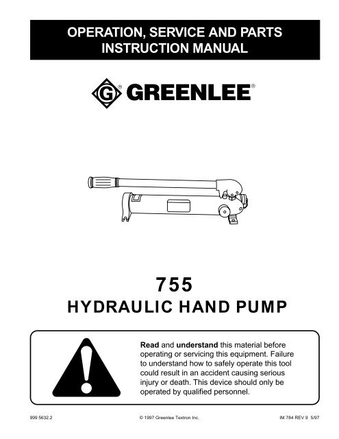
OPERATION, SERVICE AND PARTS<br />
INSTRUCTION MANUAL<br />
<strong>755</strong><br />
HYDRAULIC HAND PUMP<br />
Read and understand this material before<br />
operating or servicing this equipment. Failure<br />
to understand how to safely operate this tool<br />
could result in an accident causing serious<br />
injury or death. This device should only be<br />
operated by qualified personnel.<br />
999 5632.2 © 1997 Greenlee Textron Inc. IM 784 REV 9 5/97
<strong>755</strong> <strong>Hydraulic</strong> <strong>Hand</strong> <strong>Pump</strong><br />
Description<br />
The <strong>755</strong> <strong>Hydraulic</strong> <strong>Hand</strong> <strong>Pump</strong> develops 10,000 psi (68,950 kPa) and is intended<br />
to be used with the following Greenlee conduit benders, tubing bender,<br />
and punch driver.<br />
Conduit Benders: model 777 Punch Driver: model 1732<br />
model 880 Tubing Bender: model 782<br />
model 882<br />
model 882CB<br />
Fill with Greenlee hydraulic oil or Mobil DTE-13 only.<br />
Purpose of this Manual<br />
This instruction manual is intended to familiarize operators and maintenance<br />
personnel with the <strong>755</strong> <strong>Hydraulic</strong> <strong>Hand</strong> <strong>Pump</strong>. This manual should be kept<br />
available to the operating and maintenance personnel.<br />
SAFETY<br />
ALERT<br />
SYMBOL<br />
The symbol above is used to call your attention<br />
to instructions concerning your personal safety.<br />
Watch for this symbol. It points out important safety<br />
precautions. It means “ATTENTION! Become alert!<br />
Your personal safety is involved!” Read the<br />
message that follows and be alert to the possibility<br />
of personal injury or death.<br />
Immediate hazards which WILL, if not avoided, result in<br />
severe personal injury or death.<br />
Hazards or unsafe practices which COULD, if not avoided,<br />
result in severe personal injury or death.<br />
Hazards or unsafe practices which COULD, if not avoided,<br />
result in minor personal injury or property damage.<br />
Safety is a critical factor in the design of Greenlee equipment. The best program starts with a safety-conscious<br />
operator. The information highlighted in this bulletin describes operating practices for the benefit of the workers<br />
who will use our equipment in their daily jobs. Comments from users are appreciated.<br />
A person who has not read and does not understand all<br />
operating instructions is not qualified to operate this tool.<br />
Failure to read and understand safety instructions may<br />
result in injury or death.<br />
Greenlee Textron Inc. / Subsidiary of Textron Inc. 2 4455 Boeing Dr., Rockford, IL 61109-2988 815/397-7070
<strong>755</strong> <strong>Hydraulic</strong> <strong>Hand</strong> <strong>Pump</strong><br />
IMPORTANT SAFETY INSTRUCTIONS<br />
<strong>Electric</strong> shock hazard:<br />
This is not an insulated tool.<br />
Contact with live circuits can result<br />
in severe injury or death.<br />
Inspect pump, hoses and couplers. Replace any<br />
worn, damaged or missing components with<br />
Greenlee replacement parts.<br />
Skin injection hazard:<br />
Oil under pressure easily punctures<br />
skin causing serious injury, gangrene<br />
or death. If you are injured by<br />
escaping oil, seek medical attention<br />
immediately.<br />
• <strong>Hand</strong>-tighten all couplers<br />
completely before operating the<br />
pump. Do not use tools to tighten<br />
the couplers.<br />
• Do not use fingers or hands to<br />
check for leaks while operating<br />
the pump.<br />
• Do not hold hose or couplers<br />
while operating the pump.<br />
• Release the hydraulic pressure<br />
before disconnecting hoses or<br />
couplers, and before servicing<br />
the pump or accessory.<br />
Wear eye protection when using<br />
this pump.<br />
Follow the operating instructions and safety<br />
information supplied with the hydraulic ram or<br />
accessory.<br />
Failure to observe this warning could result in<br />
severe injury or death.<br />
• Use this tool for the manufacturer’s intended<br />
use only.<br />
• Work in areas that are well-lit, uncluttered<br />
and dry.<br />
SAVE THESE INSTRUCTIONS<br />
Additional copies of this manual are available upon request at no charge.<br />
Greenlee Textron Inc. / Subsidiary of Textron Inc. 3 4455 Boeing Dr., Rockford, IL 61109-2988 815/397-7070
<strong>755</strong> <strong>Hydraulic</strong> <strong>Hand</strong> <strong>Pump</strong><br />
Operation<br />
1. Remove the dust cap.<br />
2. Connect the hose to the bender or punch unit.<br />
Note: <strong>Hand</strong>-tighten the couplers completely.<br />
Do not use tools.<br />
3. Twist the release knob (7) clockwise until it stops.<br />
4. <strong>Pump</strong> the handle (9) until the bend or punch is<br />
complete.<br />
5. Twist the release knob (7) counterclockwise to<br />
release the hydraulic pressure.<br />
6. Disconnect the hose from the bender or punch unit.<br />
Replace all dust caps.<br />
Filling the <strong>Pump</strong> with Oil<br />
1. Clamp the pump into a vise with the end cap (1)<br />
upward. Loosen the set screw (26) and remove the<br />
end cap.<br />
2. Remove the cap screw (31) with O-ring (18) from<br />
the reservoir follower (3). Remove the follower from<br />
the reservoir. Inspect both V-packings (28); replace<br />
them if they are worn or damaged.<br />
3. Pour Greenlee hydraulic oil* into the reservoir until it<br />
is within 1-3/4" from the top.<br />
4. Reinstall the reservoir follower.<br />
5. Turn the release knob (7) counterclockwise so the<br />
valve is open. <strong>Pump</strong> the handle (9) two or three<br />
times.<br />
6. Turn the release knob (7) clockwise so the valve is<br />
closed. <strong>Pump</strong> the handle (9) two or three times.<br />
7. Slowly turn the release knob (7) to counterclockwise.<br />
This will allow any air trapped in the pump<br />
block (10) or reservoir (8) to escape.<br />
Note: Do this slowly to prevent the oil from suddenly<br />
gushing up through the cap screw hole.<br />
8. Repeat steps 5 through 7 one or two more times.<br />
9. Inspect the O-ring (18) in the cap screw (31);<br />
replace O-ring if it is worn or damaged.<br />
10. Replace the cap screw (31) with O-ring (18) in the<br />
follower (3). <strong>Hand</strong>-tighten the cap screw.<br />
11. Wipe any excess oil from the outside of the reservoir<br />
and replace the end cap (1). Tighten the set<br />
screw (26).<br />
* Order Greenlee hydraulic oil by the gallon<br />
(part number 905 1059.3) or by the quart<br />
(part number 905 0806.8).<br />
Greenlee Textron Inc. / Subsidiary of Textron Inc. 4 4455 Boeing Dr., Rockford, IL 61109-2988 815/397-7070
<strong>755</strong> <strong>Hydraulic</strong> <strong>Hand</strong> <strong>Pump</strong><br />
Troubleshooting<br />
PROBLEM PROBABLE CAUSE POSSIBLE REMEDY<br />
Oil leak at coupler. Fitting loose or damaged. Tighten or replace fitting and/or coupler.<br />
O-ring is worn or damaged.<br />
Replace O-ring.<br />
<strong>Pump</strong> builds pressure, but ram Coupler is not tightened sufficiently, <strong>Hand</strong>-tighten coupler completely so<br />
does not advance, or ram will and check balls are not engaged. check balls engage. Replace coupler<br />
not return.<br />
if necessary.<br />
Oil leak at OPEN/CLOSE O-ring and/or backup ring is worn Replace O-ring (18) and/or backup<br />
release knob. or damaged. ring (17).<br />
Release shaft is bent. Replace release shaft knob unit (7).<br />
Oil leak at plunger. O-ring, backup ring and/or washer Replace O-ring (29), backup ring (15),<br />
(Attached to handle.) are worn or damaged. and washer (16).<br />
Injector packing nut is worn. Replace injector packing nut (6).<br />
Oil leak at reservoir end. V-packing seal is worn or damaged. Replace two V-packing seals (28).<br />
Cylinder wall damaged. Replace reservoir tube (8).<br />
Can’t hold load or excessive Ball in release knob leaking. Check seat for scratches or conpumping<br />
is required. Discharge ball (20) or intake ball (22) tamination. Reseat ball or return to<br />
below discharge ball (20) is leaking. an authorized Greenlee service center<br />
for repair.<br />
Can’t raise load with excessive Intake ball (22) below discharge ball (20) Check seat for scratches or conpumping<br />
but handle is rigid. is leaking. tamination. Reseat ball or return to<br />
an authorized Greenlee service center<br />
for repair.<br />
Load on system causes handle Discharge ball (20) is leaking. Check seat for scratches or conto<br />
lift.<br />
tamination. Reseat ball or return to<br />
an authorized Greenlee service center<br />
for repair.<br />
Greenlee Textron Inc. / Subsidiary of Textron Inc. 5 4455 Boeing Dr., Rockford, IL 61109-2988 815/397-7070
<strong>755</strong> <strong>Hydraulic</strong> <strong>Hand</strong> <strong>Pump</strong><br />
Exploded View<br />
7.18<br />
5.62<br />
A<br />
5<br />
2<br />
(4) 5/16" HOLD DOWN BOLT HOLES<br />
16.50<br />
SERIAL NUMBER LOCATION<br />
19<br />
11<br />
20.22<br />
25.60<br />
10 8<br />
9 21<br />
3.75<br />
2.93<br />
A<br />
Greenlee Textron Inc. / Subsidiary of Textron Inc. 6 4455 Boeing Dr., Rockford, IL 61109-2988 815/397-7070
Exploded View (cont’d)<br />
<strong>755</strong> <strong>Hydraulic</strong> <strong>Hand</strong> <strong>Pump</strong><br />
4 12 33 13<br />
18 31<br />
6<br />
15<br />
29<br />
16<br />
1<br />
20<br />
22<br />
22<br />
25<br />
32<br />
3<br />
28<br />
26<br />
27<br />
14<br />
SECTION A-A<br />
24<br />
18 17<br />
7<br />
30<br />
34<br />
23<br />
SECTION B-B<br />
Greenlee Textron Inc. / Subsidiary of Textron Inc. 7 4455 Boeing Dr., Rockford, IL 61109-2988 815/397-7070
<strong>755</strong> <strong>Hydraulic</strong> <strong>Hand</strong> <strong>Pump</strong><br />
<strong>Pump</strong> Block Seat<br />
ø .332 (Q) DRILL<br />
ø 1/4 REAM<br />
9/32 BALL SEAT<br />
ø (11/64) REAM<br />
ø 0.238 (B) DRILL<br />
7/32 BALL SEAT<br />
ø .256 (F) DRILL<br />
(NOTE DRILL ANGLE)<br />
7/32 BALL SEAT<br />
ø 9/64 DRILL<br />
ø 5/32 REAM<br />
15°<br />
Greenlee Textron Inc. / Subsidiary of Textron Inc. 8 4455 Boeing Dr., Rockford, IL 61109-2988 815/397-7070
<strong>755</strong> <strong>Hydraulic</strong> <strong>Hand</strong> <strong>Pump</strong><br />
Parts List<br />
UPC NO.<br />
KEY 78-3310- PART NO. DESCRIPTION QTY.<br />
1 501 5721.3 Cap, End ........................................................................ 1<br />
2 501 5724.8 Lever, Injector ................................................................ 1<br />
3 501 1716.5 Reservoir Follower (Replaces 501 5814.7) ................... 1<br />
4 501 5725.6 Plunger ........................................................................... 1<br />
5 501 5726.4 Link, Lever ...................................................................... 1<br />
6 501 5727.2 Nut, Injector Packing ...................................................... 1<br />
7 501 8182.3 Release Unit (Includes Key Nos. 17, 18 and 22) ........... 1<br />
(Replaces 501 5728.0 and 501 6773.6 Units)<br />
8 500 3467.7 Reservoir Tube (Replaces 501 5730.2) ......................... 1<br />
9 501 5731.0 <strong>Hand</strong>le ............................................................................ 1<br />
10 501 5732.9 Block Weldment, <strong>Pump</strong> .................................................. 1<br />
11 501 5735.3 Pin, Fulcrum ................................................................... 2<br />
12 500 3177.5 Washer, Sealing ............................................................. 1<br />
13 500 6111.9 Spring, Compression...................................................... 1<br />
14 500 3422.7 Filter, Felt ....................................................................... 1<br />
15 905 1455.6 Ring, 9/16 x 3/4 Single Turn Scarf-Cut Back-Up ........... 1<br />
(Replaces 905 1173.5)<br />
16 501 5736.1 Washer, Sealing ............................................................. 1<br />
17 905 3853.6 Ring, 1/4 x 3/8 Teflon Spiral Back-Up ............................ 1<br />
18 905 0418.6 O-Ring, 1/4 x 3/8 x 1/16 ................................................. 2<br />
19 905 0434.8 Ring, Retaining ............................................................... 4<br />
20 905 0436.4 Ball, 9/32 dia. Grade #1 Chrome Steel .......................... 1<br />
21 905 1174. 3 Grip, 1-1/16 ID x 1-3/8 OD x 5" Long Plastic ................. 1<br />
22 905 0452.6 Ball, 7/32 Dia. Grade #1 Chrome Steel ......................... 2<br />
23 905 0385.6 O-Ring, 2-1/8 x 2-3/8 x 1/8 (Replaces 905 4770.5*) ..... 1<br />
24 905 0449.6 Pin, 5/16 x 1-1/4 ............................................................. 1<br />
25 905 0619.7 Screw, 5/16-18 NC x 1/4 Flat Point Socket Set ............. 1<br />
26 905 0617.0 Screw, 1/4-20 NC x 1/4 Flat Point Screw Socket Set .... 1<br />
27 905 0744.4 Ring, Retaining ............................................................... 1<br />
28 905 0745.2 V-Packing, 2-1/4 OD x 1-7/8 ID x 3/16 .......................... 2<br />
29 905 0782.7 O-Ring, 9/16 x 3/4 x 3/32 (Replaces 905 4771.3*) ........ 1<br />
30 905 0807.6 Quick-Coupler, 3/8 NPTF ............................................... 1<br />
31 905 0558.1 Screw, 5/16-18 NC x 1/2 Fillister Head Cap .................. 1<br />
32 905 0885.8 Pin, 1/4 x 3/8 Spiral ........................................................ 1<br />
33 905 1450.5 Screw, 3/8-24 NF x 1/2 Skt. Hd. Cap ............................. 1<br />
(Replaces 905 0904.8)<br />
34 905 1137.9 Elbow, 3/8-18 NPTF x 90° Street ................................... 1<br />
37 905 0441.0 Oil, Greenlee <strong>Hydraulic</strong> ............................................... 1 Qt.<br />
502 0450.5 Decal, Product/Safety/Caution ....................................... 1<br />
Optional Parts<br />
501 8272.2 Kit, Packing Repair<br />
*Fluorocarbon O-rings used at factory as part of production process.<br />
Greenlee Textron Inc. / Subsidiary of Textron Inc. 9 4455 Boeing Dr., Rockford, IL 61109-2988 815/397-7070
Greenlee Textron Inc. / Subsidiary of Textron Inc.<br />
4455 Boeing Drive, Rockford, IL 61109-2988 USA<br />
General Offices: 815/397-7070<br />
Customer Center and Field Service: 800/435-0786<br />
Fax (24 Hour) Customer Center: 800/451-2632 • 815/397-1865<br />
Canada Fax (24 Hour) Customer Center: 800/524-2853<br />
Printed in the U.S.A.