V2400 Plugmold Installation Instructions - by Legrand
V2400 Plugmold Installation Instructions - by Legrand
V2400 Plugmold Installation Instructions - by Legrand

Create successful ePaper yourself
Turn your PDF publications into a flip-book with our unique Google optimized e-Paper software.
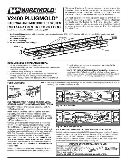
<strong>V2400</strong> PLUGMOLD ®<br />
RACEWAY AND MULTIOUTLET SYSTEM<br />
INSTALLATION INSTRUCTIONS<br />
<strong>Installation</strong> Instruction No.: 40063R2 – Updated July 2004<br />
Wiremold Electrical Systems conform to and should be<br />
installed and properly grounded in compliance with<br />
requirements of the current National Electrical Code, Canadian<br />
Electrical Code or codes administered <strong>by</strong> local authorities.<br />
All electrical products may represent possible shock or fire<br />
hazard if improperly installed or used. Wiremold electrical<br />
products are UL Listed to U.S. and Canadian safety<br />
standards, made for interior use only, and should be installed<br />
in conformance with current local and/or the National<br />
Electrical Code.<br />
1 No. <strong>V2400</strong>B Base section with grounding type receptacles rated 20A, 125V prewired with No. 12 type THHN conductors and<br />
snapped into base.<br />
Receptacles<br />
<strong>V2400</strong>B &<br />
1 No. 2400C Cover section<br />
Harness<br />
1 No. 2410 Coupling<br />
2 No. V2410B Blank End Fittings<br />
<strong>V2400</strong>B<br />
<strong>V2400</strong>C<br />
RECOMMENDED INSTALLATION STEPS:<br />
1. Lay out raceway path on mounting surface.<br />
2. Locate power feed point, then install raceway base & harness (See<br />
instructions that follow).<br />
3. Commence wiring according to instructions.<br />
4. Install raceway covers. If any cuts are necessary, hold raceway<br />
cover up against mounted raceway base/harness so that<br />
receptacle holecuts match with receptacles. Mark cover and cut<br />
5.Install fitting cover last over raceway covers (excluding 2410A<br />
Entrance End Cover).<br />
NOTE: FOR EASE OF INSTALLATION AT CORNERS – Cut out any<br />
receptacle within 4" of wall corner. This will allow sufficient space<br />
within raceway for wire connections where two runs meet. Cut a blank<br />
raceway cover piece to fit over any exposed area, if necessary.<br />
FEED METHODS:<br />
Fig.1A<br />
V2410A ENTRANCE<br />
END FITTING<br />
2 1/2"<br />
<strong>V2400</strong>B<br />
END FEEDING FROM FLEXIBLE OR RIGID METAL<br />
CONDUIT (USING V2410A ENTRANCE END FITTING)<br />
Mount <strong>V2400</strong> Base and harness on surface with No.<br />
10 Panhead screws.<br />
Insert V2410A Entrance End Fitting base (available<br />
separately) into end of <strong>V2400</strong>B Raceway Base.<br />
Assemble 1/2" connector (not supplied) with V2410A<br />
and bring in feed cable with wires extending at least 2<br />
1/2" beyond connector.<br />
Connect green conductor infeed which is connected<br />
directly to the service grounding terminal using 2409<br />
Ground Clamp, or equivalent approved method for<br />
equipment grounding connections. Connect black and<br />
white harness wires to black and white feed wires with<br />
W30 Wire Connectors (available separately) inserting<br />
only conductors of same color in a connector. See<br />
“W30 Wire Connectors… How to Use”. DO NOT USE<br />
W30 WIRE CONNECTORS WITH GROUND WIRES.<br />
Any unused wire leads must be individually closed up<br />
with a wire nut. DO NOT CONNECT UNUSED LEADS<br />
TOGETHER.<br />
Snap V2410A Fitting Cover onto raceway base. Cut<br />
raceway cover to fit and snap onto raceway base.<br />
NOTE: Units may be end-fed as in Step 1A through V2410A Entrance End Fittings or, back-fed as in 2A or<br />
2B through 1/2" entrance knockouts in base.<br />
Black<br />
W30 Connector<br />
White<br />
Fig. 2A W30 METHOD<br />
Black<br />
White<br />
Ground<br />
Ground<br />
Fig. 2B WIRE NUT METHOD<br />
Wire Nut<br />
<strong>V2400</strong>B<br />
Wire Nut<br />
Jumper<br />
Jumper<br />
BACK FEEDING FROM FLEXIBLE OR RIGID METAL CONDUIT<br />
Cut hot, neutral and ground wires of <strong>V2400</strong> Raceway Harness at location of raceway<br />
base entrance knockout that will be removed. Remove 1/2" entrance knockout from<br />
base and attach 1/2" feed connector (not supplied). Mount raceway base with<br />
harness using No.10 Panhead screws. Connect harness to feed wires using one of<br />
the approved methods shown above in Fig. 2A or Fig. 2B<br />
W30 WIRE CONNECTORS… HOW TO USE<br />
W30 pressure-type connectors<br />
(available separately) are for common<br />
connection of 2, 3, or 4 No. 12 or<br />
No. 14 solid conductors.<br />
NOT TO BE USED TO CONNECT GROUNDING CONDUCTORS.<br />
<strong>V2400</strong>B
COUPLING TWO PLUGMOLD <strong>V2400</strong> WIRED SECTIONS TOGETHER TO EXTEND RUN (USING 2401 COUPLING)<br />
Insert 2401 Coupling halfway into one end<br />
of raceway base. Mount raceway using No.<br />
10 Panhead screws.<br />
Insert second raceway base section onto<br />
the opposite end of of 2401 Coupling.<br />
Mount second raceway section with No.<br />
Panhead screws.<br />
Connect green conductor in feed which<br />
is connected directly to the service<br />
grounding terminal using 2409 Ground<br />
Clamp or equivalent approved method<br />
for equipment grounding connections.<br />
Connect black and white harness wires to<br />
black and white feed wires with W30 Wire<br />
Connectors (available separately) inserting<br />
only conductors of same color in a<br />
connector. See “W30 Wire Connectors…<br />
How to Use” Do not use W30 Wire<br />
Connectors with Ground wires. Any<br />
unused wire leads must be individually<br />
closed up with a wire nut. Do Not connect<br />
unused leads together.<br />
Snap V2410A Fitting Cover onto raceway<br />
base. Cut Raceway cover to fit and snap<br />
onto raceway base.<br />
2401 Coupling<br />
<strong>V2400</strong>B<br />
V2406 CONNECTION COVER<br />
V2406 may be used to<br />
cover gaps between<br />
raceway covers. Snap<br />
V2406 onto raceway<br />
at each joint.<br />
<strong>V2400</strong>C<br />
V2406<br />
Connection<br />
Cover<br />
2400WC WIRE CLIP<br />
Use 2400WC Wire Clips<br />
(available separately) if<br />
necessary to contain wires.<br />
2400WC<br />
Wire Clip<br />
<strong>V2400</strong>B<br />
V2417 INTERNAL ELBOW<br />
V2417<br />
Coupling<br />
Base<br />
<strong>V2400</strong>B<br />
V2417<br />
<strong>V2400</strong>B<br />
Insert short end of V2417<br />
Coupling Base into <strong>V2400</strong>B<br />
Raceway Base. Mount the<br />
assembly to surface.<br />
Insert the other <strong>V2400</strong>B Base into V2417<br />
Coupling. This base section must be in<br />
contact with base already assembled to<br />
short leg of V2417 Coupling Base. DO<br />
NOT LEAVE ANY GAPS BETWEEN THE<br />
TWO BASES. Mount to surface with No.<br />
10 Panhead screws.<br />
V2417<br />
Cover<br />
Install raceway cover next. If necessary<br />
use a blank cover piece for covering any<br />
exposed area. DO NOT LEAVE ANY<br />
GAPS BETWEEN RACEWAY COVERS.<br />
Snap V2417 Cover onto raceway cover<br />
at corner.<br />
NOTE: FOR EASE OF INSTALLATION AT CORNERS – Cut out any receptacle within 4" of wall corner. This will allow sufficient space<br />
within raceway for wire connections where two runs meet. Cut a blank raceway cover piece to fit over any exposed area, if necessary.<br />
WIRE CAPACITY<br />
RACEWAY (without receptacles)<br />
#8 #10 #12 #14<br />
THHN TW THHN TW THHN TW THHN TW<br />
15 AMP 13 10 26 22 41 28 56 36<br />
20 AMP 13 10 26 22 41 28 – –<br />
Wired Section Nos.<br />
V24GB306<br />
36"<br />
6" 12" 12"<br />
3" 6" 9" 12" 15" 21" 24" 27" 33"<br />
Base<br />
PLUGMOLD MULTIOUTLET SYSTEM<br />
(20 Amp Prewired GB Series)<br />
#8 THHN #10 THHN #12 THHN #14 THHN<br />
20 AMP 2 4 6 –<br />
V24GB506<br />
V24GB512<br />
V24GB606<br />
V24GB612<br />
V24GB618<br />
60"<br />
3" 6" 9" 12" 15" 21" 24" 27" 33" 36" 39" 45" 48" 51" 57"<br />
72"<br />
3" 6" 9" 12" 15" 21" 24" 27" 33" 36" 39" 45" 48" 51" 57" 60" 63" 69 "<br />
The Wiremold Company<br />
U.S. and International:<br />
60 Woodlawn Street • West Hartford, CT 06110<br />
1-800-621-0049 • FAX 860-232-2062 • Outside U.S.: 860-233-6251<br />
Canada:<br />
850 Gartshore Street • Fergus, Ontario N1M 2W8<br />
1-800-741-7957 • FAX 519-843-5980<br />
© Copyright 2004 The Wiremold Company All Rights Reserved<br />
40063R2 – Updated July 2004 – For latest specs visit www.wiremold.com