Instructions - Water Heater Timers Save Money
Instructions - Water Heater Timers Save Money
Instructions - Water Heater Timers Save Money

You also want an ePaper? Increase the reach of your titles
YUMPU automatically turns print PDFs into web optimized ePapers that Google loves.
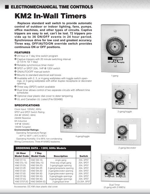
ELECTROMECHANICAL TIME CONTROLS<br />
KM2 In-Wall <strong>Timers</strong><br />
Replaces standard wall switch to provide automatic<br />
control of outdoor or indoor lighting, fans, pumps,<br />
office machines, and other types of circuits. Captive<br />
trippers are easy to set, can’t be lost. 72 trippers provide<br />
up to 36 ON/OFF events in 24 hour period.<br />
Synchronous drive for low cost and greatest accuracy.<br />
Three way, OFF/AUTO/ON override switch provides<br />
continuous ON or OFF positions.<br />
FEATURES<br />
✪ 24 hour or 7 day time switch program<br />
✪ Captive trippers with 20 minute switching interval<br />
(2-1/3 hr. for 7 day)<br />
✪ Reliable synchronous timer motor<br />
✪ SPST or SPDT 20A, 1HP @ 120V switch<br />
✪ ON/AUTO/OFF manual switch<br />
✪ Mounts to standard electrical wall boxes<br />
✪ Available with 2, 3, or 4-gang wallplates with toggle switch openings,<br />
or 2-gang wallplates with either duplex receptacle or decorator<br />
opening<br />
✪ Three way (SPDT) switch available<br />
✪ Dual timer allows control of two separate circuits with different time<br />
schedules<br />
✪ Optional clear plastic dial cover to deter tampering<br />
✪ UL and Canadian UL Listed (File E83486)<br />
1-gang<br />
SPECIFICATIONS<br />
Clock Input: 120VAC, 60Hz<br />
SPST and SPDT Switch Rating:<br />
20A @ 120VAC, 60Hz<br />
2400W Resistive<br />
8A Inductive<br />
1HP @ 120VAC<br />
1350W Tungsten<br />
Environmental Ratings:<br />
Operating Temperature Range:<br />
–40°F to 180°F (–40°C to 85°C)<br />
Operating Humidity: 0 to 95% non-condensing<br />
Wiring Connections: Three #14AWG leadwires<br />
ORDERING DATA – 120V, 60Hz Models<br />
4-gang/toggle<br />
2-gang/toggle<br />
2-gang/decorator<br />
24 Hour 7 Day<br />
Model Code Model Code Description Switch<br />
KM2 ST-1G KM2 SW-1G single gang 20A, SPST<br />
KM2 STu-1G KM2 SWu-1G three-way single gang 20A, SPDT<br />
KM2 ST-2G KM2 SW-2G 2-gang/toggle opening 20A, SPST<br />
KM2 ST-2R KM2 SW-2R 2-gang/receptacle opening 20A, SPST<br />
KM2 ST-2D KM2 SW-2D 2-gang/decorator opening 20A, SPST<br />
KM2 ST-3D KM2 SW-3D 3-gang/decorator opening 20A, SPST<br />
KM2 ST-3G KM2 SW-3G 3-gang/toggle openings 20A, SPST<br />
KM2 ST-4G KM2 SW-4G 4-gang/toggle openings 20A, SPST<br />
KM2 STST-2G KM2 SWSW-2G 2-gang/dual timer (2) 20A, SPST<br />
Accessories: DC-KM clear plastic dial cover.<br />
Dual Timer<br />
(2-gang with 2 KM2’s)
Installation<br />
TO THE INSTALLER<br />
1. Read the operating instructions carefully.<br />
2. Check the input and output ratings marked on the<br />
unit to make sure this product is suitable for your<br />
application.<br />
3. Disconnect power supply prior to installation to prevent<br />
electrical shock.<br />
4. Damage to the contacts caused by short circuiting<br />
will void warranty.<br />
5. Wire in accordance with National and local electrical<br />
code requirements.<br />
BE SURE ALL CONNECTIONS ARE SECURE.<br />
DOUBLE CHECK ALL TWIST-ON WIRE CON-<br />
NECTORS.<br />
6. Mount timer into wall box using supplied screws.<br />
7. If timer does not operate, check that the timer’s black<br />
wire is connected to hot line and not the load. If necessary,<br />
reverse connections to red and black wires.<br />
Manual Operation<br />
The slide switch provides manual operation of the<br />
load, overriding the timer. Set to the “OFF” position,<br />
the load will be continuously off, and if set to “ON”, it<br />
will be continuously on. For automatic timed on’s and<br />
off’s, the switch must be in the “AUTO” position.<br />
Wiring Diagram<br />
Programming<br />
The timer dial contains 72 “trippers” which, when set<br />
at the inner perimeter of the dial, will turn the switch<br />
“ON” at the time adjacent to the tripper. The switch will<br />
return to the “OFF” position when the timer progresses<br />
past the inward trippers.<br />
The 72 trippers allow multiple on/off sequences with a<br />
minimum on or off time of 20 min. To program, set all<br />
trippers inward for the duration of the on event.<br />
For example, to turn lights on at 5:00pm and off at<br />
11:00pm, leave inward the 18 trippers between 5 and<br />
11 on the “pm” side of the dial. Make sure manual<br />
switch is in the “AUTO” position.<br />
NOTE: For any times where “OFF” programming is<br />
desired, the trippers must be moved to the outer<br />
perimeter of the dial.<br />
Setting The Time<br />
Rotate the dial clockwise until the correct time and<br />
“am” or “pm” is opposite the arrow on the plate.<br />
CAUTION: Do not turn dial counter-clockwise, as the<br />
timer will be damaged.<br />
ONE YEAR WARRANTY<br />
If this unit fails due to a defect in material or workmanship<br />
within one year after purchase, Grasslin<br />
will repair or replace the unit free of charge. This<br />
warranty does not apply to damage due to accidents,<br />
abuse, mishandling nor to units not used in<br />
accordance with directions. This warranty gives you<br />
specific legal rights, and you may also have other<br />
rights which vary from state to state.<br />
LINE (BLACK)<br />
LOAD (RED)<br />
LOAD<br />
NEUTRAL (WHITE)<br />
Distributed by:<br />
Printed in USA 092 05.01