
Create successful ePaper yourself
Turn your PDF publications into a flip-book with our unique Google optimized e-Paper software.
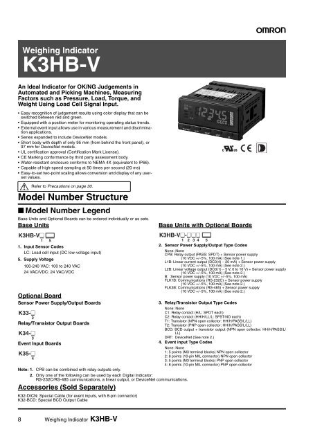
Weighing Indicator<br />
<strong>K3HB</strong>-V<br />
An Ideal Indicator for OK/NG Judgements in<br />
Automated and Picking Machines, Measuring<br />
Factors such as Pressure, Load, Torque, and<br />
Weight Using Load Cell Signal Input.<br />
• Easy recognition of judgement results using color display that can be<br />
switched between red and green.<br />
• Equipped with a position meter for monitoring operating status trends.<br />
• External event input allows use in various measurement and discrimination<br />
applications.<br />
• Series expanded to include DeviceNet models.<br />
• Short body with depth of only 95 mm (from behind the front panel), or<br />
97 mm for DeviceNet models.<br />
• UL certification approval (Certification Mark License).<br />
• CE Marking conformance by third party assessment body.<br />
• Water-resistant enclosure conforms to NEMA 4X (equivalent to IP66).<br />
• Capable of high-speed sampling at 50 times per second (20 ms)<br />
• Easy-to-set two-point scaling allows conversion and display of any userset<br />
values.<br />
Refer to Precautions on page 30.<br />
Model Number Structure<br />
■ Model Number Legend<br />
Base Units and Optional Boards can be ordered individually or as sets.<br />
Base Units<br />
<strong>K3HB</strong>-V@<br />
1<br />
1. Input Sensor Codes<br />
LC: Load cell input (DC low-voltage input)<br />
5. Supply Voltage<br />
100-240 VAC: 100 to 240 VAC<br />
24 VAC/VDC: 24 VAC/VDC<br />
Optional Board<br />
Sensor Power Supply/Output Boards<br />
K33-@<br />
2<br />
Relay/Transistor Output Boards<br />
K34-@<br />
3<br />
Event Input Boards<br />
K35-@<br />
4<br />
<strong>K3HB</strong>-V@-@@@<br />
5 1 2 3 4<br />
Note: 1. CPB can be combined with relay outputs only.<br />
2. Only one of the following can be used by each Digital Indicator:<br />
RS-232C/RS-485 communications, a linear output, or DeviceNet communications.<br />
Accessories (Sold Separately)<br />
K32-DICN: Special Cable (for event inputs, with 8-pin connector)<br />
K32-BCD: Special BCD Output Cable<br />
Base Units with Optional Boards<br />
5<br />
2. Sensor Power Supply/Output Type Codes<br />
None: None<br />
CPB: Relay output (PASS: SPDT) + Sensor power supply<br />
(10 VDC +/−5%, 100 mA) (See note 1.)<br />
L1B: Linear current output (DC0(4) − 20 mA) + Sensor power supply<br />
(10 VDC +/−5%, 100 mA) (See note 2.)<br />
L2B: Linear voltage output (DC0(1) − 5 V, 0 to 10 V) + Sensor power supply<br />
(10 VDC +/−5%, 100 mA) (See note 2.)<br />
B: Sensor power supply (10 VDC +/−5%, 100 mA)<br />
FLK1B: Communications (RS-232C) + Sensor power supply<br />
(10 VDC +/−5%, 100 mA) (See note 2.)<br />
FLK3B: Communications (RS-485) + Sensor power supply<br />
(10 VDC +/−5%, 100 mA) (See note 2.)<br />
3. Relay/Transistor Output Type Codes<br />
None: None<br />
C1: Relay contact (H/L: SPDT each)<br />
C2: Relay contact (HH/H/LL/L: SPST-NO each)<br />
T1: Transistor (NPN open collector: HH/H/PASS/L/LL)<br />
T2: Transistor (PNP open collector: HH/H/PASS/L/LL)<br />
BCD: BCD output + transistor output (NPN open collector: HH/H/PASS/L/<br />
LL)<br />
DRT: DeviceNet (See note 2.)<br />
4. Event input Type Codes<br />
None: None<br />
1: 5 points (M3 terminal blocks) NPN open collector<br />
2: 8 points (10-pin MIL connector) NPN open collector<br />
3: 5 points (M3 terminal blocks) PNP open collector<br />
4: 8 points (10-pin MIL connector) PNP open collector<br />
8 Weighing Indicator <strong>K3HB</strong>-V
Specifications<br />
■ Ratings<br />
Power supply voltage<br />
Allowable power supply voltage range<br />
Power consumption<br />
(See note 1.)<br />
Current consumption<br />
Input<br />
A/D conversion method<br />
External power supply<br />
Event inputs<br />
Timing input<br />
(See note 2.)<br />
Output ratings (depends<br />
on the model)<br />
Display method<br />
Startup compensation<br />
timer input<br />
Hold input<br />
Reset input<br />
Forced-zero input<br />
Bank input<br />
Relay output<br />
Transistor output<br />
Linear output<br />
100 to 240 VAC (50/60 Hz), 24 VAC/VDC, DeviceNet power supply: 24 VDC<br />
85% to 110% of the rated power supply voltage, DeviceNet power supply: 11 to 25 VDC<br />
100 to 240 V: 18 VA max. (max. load)<br />
24 VAC/DC: 11 VA/7 W max. (max. load)<br />
DeviceNet power supply: 50 mA max. (24 VDC)<br />
DC voltage<br />
Delta-Sigma method<br />
See Sensor Power Supply/Output Type Codes<br />
NPN open collector or no-voltage contact signal<br />
ON residual voltage: 3 V max.<br />
ON current at 0 Ω: 17 mA max.<br />
Max. applied voltage: 30 VDC max.<br />
OFF leakage current: 1.5 mA max.<br />
NPN open collector or no-voltage contact signal<br />
ON residual voltage: 2 V max.<br />
ON current at 0 Ω: 4 mA max.<br />
Max. applied voltage: 30 VDC max.<br />
OFF leakage current: 0.1 mA max.<br />
250 VAC, 30 VDC, 5 A (resistive load)<br />
Mechanical life expectancy: 5,000,000 operations, Electrical life expectancy: 100,000 operations<br />
Maximum load voltage: 24 VDC, Maximum load current: 50 mA, Leakage current: 100 μA max.<br />
Linear output 0 to 20 mA DC, 4 to 20 mA:<br />
Load: 500 Ω max, Resolution: Approx. 10,000, Output error: ±0.5% FS<br />
Linear output 0 to 5 VDC, 1 to 5 VDC, 0 to 10 VDC:<br />
Load: 5 kΩ max, Resolution: Approx. 10,000, Output error: ±0.5% FS<br />
(1 V or less: ±0.15 V; not output for 0 V or less)<br />
Negative LCD (backlit LED) display<br />
7-segment digital display (Character height: PV: 14.2 mm (green/red); SV: 4.9 mm (green)<br />
Main functions<br />
Scaling function, measurement operation selection, averaging, previous average value comparison, forcedzero,<br />
zero-limit, output hysteresis, output OFF delay, output test, teaching, display value selection, display<br />
color selection, key protection, bank selection, display refresh period, maximum/minimum hold, reset<br />
Ambient operating temperature<br />
−10 to 55°C (with no icing or condensation)<br />
Ambient operating humidity 25% to 85%<br />
Storage temperature<br />
−25 to 65°C (with no icing or condensation)<br />
Altitude<br />
2,000 m max.<br />
Accessories<br />
Watertight packing, 2 fixtures, terminal cover, unit stickers, operation manual. DeviceNet models also include<br />
a DeviceNet connector (Hirose HR31-5.08P-5SC(01)) and crimp terminals (Hirose HR31-SC-121) (See note<br />
3.)<br />
Note: 1. DC power supply models require a control power supply capacity of approximately 1 A per Unit when power is turned ON. Particular<br />
attention is required when using two or more DC power supply models. The OMRON S8VS-series DC Power Supply Unit is recommended.<br />
2. PNP input types are also available.<br />
3. For <strong>K3HB</strong>-series DeviceNet models, use only the DeviceNet Connector included with the product. The crimp terminals provided are for<br />
Thin Cables.<br />
Weighing Indicator <strong>K3HB</strong>-V 9
■ Characteristics<br />
Display range −19,999 to 99,999<br />
Sampling period<br />
20 ms (50 times/second)<br />
Comparative output response time 100 ms max.<br />
Linear output response time 150 ms max.<br />
Insulation resistance<br />
20 MΩ min. (at 500 VDC)<br />
Dielectric strength<br />
2,300 VAC for 1 min between external terminals and case<br />
Noise immunity<br />
100 to 240 VAC models:<br />
±1,500 V at power supply terminals in normal or common mode<br />
(waveform with 1-ns rising edge and pulse width of 1 μs/100 ns)<br />
24 VAC/VDC models:<br />
±1,500 V at power supply terminals in normal or common mode<br />
(waveform with 1-ns rising edge and pulse width of 1 μs/100 ns)<br />
Vibration resistance<br />
Frequency: 10 to 55 Hz; Acceleration: 50 m/s 2 , 10 sweeps of 5 min each in X, Y, and Z directions<br />
Shock resistance<br />
150 m/s 2 (100 m/s 2 for relay outputs) 3 times each in 3 axes, 6 directions<br />
Weight<br />
Approx. 300 g (Base Unit only)<br />
Degree of Front panel Conforms to NEMA 4X for indoor use (equivalent to IP66)<br />
protection<br />
Rear case IP20<br />
Terminals IP00 + finger protection (VDE0106/100)<br />
Memory protection<br />
EEPROM (non-volatile memory)<br />
Number of rewrites: 100,000<br />
Applicable standards<br />
UL61010C-1, CSA C22.2 No. 1010.1 (evaluated by UL)<br />
EN61010-1 (IEC61010-1): Pollution degree 2/Overvoltage category II<br />
EN61326: 1997, A1: 1998, A2: 2001<br />
EMC<br />
EMI: EN61326+A1 industrial applications<br />
Electromagnetic radiation interference<br />
CISPR 11 Group 1, Class A: CISPRL16-1/-2<br />
Terminal interference voltage<br />
CISPR 11 Group 1, Class A: CISPRL16-1/-2<br />
EMS: EN61326+A1 industrial applications<br />
Electrostatic Discharge Immunity<br />
EN61000-4-2: 4 kV (contact), 8 kV (in air)<br />
Radiated Electromagnetic Field Immunity<br />
EN61000-4-3: 10 V/m 1 kHz sine wave amplitude modulation (80 MHz to 1 GHz)<br />
Electrical Fast Transient/Burst Immunity<br />
EN61000-4-4: 2 kV (power line), 1 kV (I/O signal line)<br />
Surge Immunity<br />
EN61000-4-5: 1 kV with line (power line), 2 kV with ground (power line)<br />
Conducted Disturbance Immunity<br />
EN61000-4-6: 3 V (0.15 to 80 MHz)<br />
Voltage Dips and Interruptions Immunity<br />
EN61000-4-11: 0.5 cycle, 0°/180°, 100% (rated voltage)<br />
10 Weighing Indicator <strong>K3HB</strong>-V
■ Input Ranges (Measurement Range and Accuracy)<br />
Input type Range Set value Measurement range Input impedance Accuracy Allowable<br />
instantaneous<br />
overload (30 s)<br />
<strong>K3HB</strong>-VLC<br />
A a Ud 0.00 to 199.99 mV 1 MΩ min. ±0.1%rdg ± 1 digit max. ±200 V<br />
Load Cell, mV B b Ud 0.000 to 19.999 mV ±0.1%rdg ± 5 digits max.<br />
C c Ud ±100.00 mV ±0.1%rdg ± 3 digits max.<br />
D d Ud ±199.99 mV ±0.1%rdg ± 1 digit max.<br />
Note: 1. The accuracy is for an ambient temperature of 23±5°C. For all ranges,10% or less of max. input ±0.1% FS.<br />
2. The letters “rdg” mean “reading.”<br />
(mV)<br />
Input type a lc b lc c lc d lc<br />
Connected<br />
terminals<br />
200.000<br />
150.000<br />
100.000<br />
50.000<br />
0.00<br />
−50.00<br />
−100.00<br />
−150.00<br />
−200.00<br />
E2 E6 E3 E6 E4 E6 E5 E6<br />
199.99 199.99<br />
19.999<br />
0.00 0.000<br />
100.00<br />
−100.00<br />
−199.99<br />
The area shown in dark shading indicates the factory setting.<br />
■ Load Cell Wiring Example<br />
+10 V<br />
B<br />
E<br />
■ Scaling Example Using Range A<br />
Indicated on the <strong>K3HB</strong>-V as 0 to 49N in the load cell specifications<br />
(rated load 49N, recommended applied voltage 10 V, rated output 2<br />
mV/V) (See note.)<br />
B5<br />
B6<br />
E2<br />
E3<br />
E4<br />
E5<br />
E6<br />
+<br />
−<br />
0 V<br />
+OUT<br />
+IN<br />
Load cell<br />
−IN<br />
−OUT<br />
Display value<br />
49 N Scaling values:<br />
inp.a1=000.00<br />
dsp.a1=00000<br />
inp.a2=020.00<br />
dsp.a2=49000<br />
dp decimal point position: 00.000<br />
Input value<br />
20 mV<br />
Note: 2 mV/V indicates a load cell output of 2 mV for 1 V applied voltage<br />
for the rated load (when using a load of 1 N). When the applied<br />
voltage is 10 V, the load cell output is 20 mV (2 mV × 10).<br />
Weighing Indicator <strong>K3HB</strong>-V 11