Laminar Flow Element
Laminar Flow Element
Laminar Flow Element

Create successful ePaper yourself
Turn your PDF publications into a flip-book with our unique Google optimized e-Paper software.
<strong>Laminar</strong> <strong>Flow</strong> <strong>Element</strong><br />
<strong>Laminar</strong> <strong>Flow</strong> <strong>Element</strong><br />
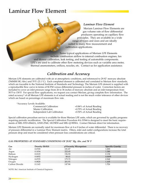
Meriam <strong>Laminar</strong> <strong>Flow</strong> <strong>Element</strong>s are<br />
gas volume rate of flow differential<br />
producers operating on capillary flow<br />
principles. They are available in a wide<br />
range of types and sizes and are ideally<br />
suited to many flow measurement and<br />
calibration applications.<br />
Some typical applications of Meriam LFE <strong>Element</strong>s<br />
include: combustion airflow to internal combustion engines, fan<br />
and blower calibration, leak testing, and testing of automobile components.<br />
LFE’s are used to calibrate other flow metering devices such as variable area meter,<br />
thermal anemometers, orifices, nozzles, etc. Contact us for application assistance.<br />
Calibration and Accuracy<br />
Meriam LFE elements are calibrated with air at atmospheric conditions, and referenced to 29.92" mercury absolute<br />
(760MM HG Abs.) and 70˚F. (21.1˚C). Each completed element is calibrated and correlated to Meriam flow standards,<br />
which are traceable to the National Institute of Standards and Technology. The Meriam LFE element is supplied with<br />
a reproducible flow curve in terms of SCFM versus differential pressure in inches of water. Correction factors are<br />
included to cover an inlet pressure range from 26 to 36 inches of mercury absolute and an inlet temperature from<br />
50˚F to 150˚F. For special flow applications, we request you contact Meriam, giving complete flow information. The<br />
rated accuracy* of all Meriam LFE elements is of actual reading and is not the much wider tolerance of other devices<br />
which are based on percentage of maximum flow rate.<br />
*Accuracy Levels Available:<br />
Commercial Calibration<br />
Master Calibration<br />
Independent Lab Calibration<br />
+0.86% of Actual Reading<br />
+0.70% of Actual Reading<br />
+0.50% of Actual Reading<br />
Special calibration procedure service is available for those Meriam LFE units, which are governed by quality programs<br />
requiring periodic recalibration. The Special Calibration Procedure #A-33544 is designed to meet the basic requirements<br />
of MIL-STD-45662A, ANSI Z540, 10CFR50 and MIL-Q-9858A. Contact Meriam direct for information.<br />
Meriam LFE <strong>Element</strong>s are normally rated for maximum flow at 4 or 8 inches of water differential. There is no recovery<br />
of pressure differential in a <strong>Laminar</strong> <strong>Flow</strong> <strong>Element</strong> matrix. Filters, inlet and outlet configurations increase the total<br />
pressure drop and must be considered when pressure loss considerations are critical.<br />
GAS PROPERTIES AT STANDARD CONDITIONS OF 29.92" Hg. Abs. and 70˚F<br />
Gas Density (lb/ft3) µViscosity Micropoises Specific Gravity<br />
Air 0.0749 181.87 1.000<br />
Argon 0.1034 222.45 1.380<br />
Helium 0.0103 196.90 0.138<br />
Hydrogen 0.0052 88.41 0.0695<br />
Nitrogen 0.0725 175.72 0.968<br />
Oxygen 0.0828 201.91 1.105<br />
Carbon Dioxide 0.1143 147.84 1.526<br />
NOTE: Ref. American Institute of Chemical Engineers<br />
24
LFE Sizing Worksheet<br />
Date:<br />
Customer Name:<br />
Address:<br />
City, State, Zip:<br />
POC:<br />
Phone:<br />
Fax:<br />
Customer No. :<br />
MERIAM No. :<br />
Tag or ID No. :<br />
Service Description:<br />
GAS: (AIR) (ARGON) (CARBON DIOXIDE) (HELIUM) (HYDROGEN)<br />
(NITROGEN)<br />
(OXYGEN)<br />
STANDARD CONDITIONS: DEG (70 DEG F)<br />
(29.92" HG ABS.)<br />
TEMPERATURE AT FLOW:<br />
DEG (F) (C) (R) (K)<br />
FLOWING PRESSURE UNITS: (“Hg @ 0 DEG C) (mm Hg @ 0 DEG C) (“ H 2 O @ 4 DEG C)<br />
(mm H 2 O @ 4 DEG C) (cm H 2 O @ 4 DEG C) (PSI)<br />
(Kg/m 2 ) (Bar) (MILLIBAR) (PASCALS)<br />
FLOW: (MASS) (POUNDS) (KILOGRAMS)<br />
(SECONDS) (MINUTE) (HOUR)<br />
(VOLUME) (ACTUAL) (STANDARD)<br />
(CUBIC CENTIMETER) (CUBIC FOOT) (CUBIC METER) (LITER)<br />
(SECONDS) (MINUTE) (HOUR)<br />
SPECIFIC GRAVITY: (MOLECULAR WT. OF FLOWING GAS / 28.95)<br />
VISCOSITY: (MP) (CP) (LB. SEC/FT 2 ) (LB/(FT•S))<br />
(PASCAL SEC)<br />
DENSITY (LB/FT 3 ) (Kg/CM 3 ) (Kg/M 3 ) (g/CM 3 )<br />
25
Meriam LFE Quick Selection Chart<br />
Model 50MK10<br />
MODEL NUMBER & DESCRIPTION<br />
Pipe Size<br />
MODEL<br />
NOMINAL AIR FLOW RANGE<br />
STANDARD CUBIC FEET/MINUTE<br />
(29.92" Hg. Abs. & 70˚F) (SCFM)<br />
Utilizes stainless steel<br />
capillary tubes cemented<br />
into a stainless steel body.<br />
Inlet, outlet, and differential<br />
pressure connections are<br />
1/4" NPT.<br />
1/4"<br />
1/4"<br />
1/4"<br />
1/4"<br />
1/4"<br />
1/4"<br />
1/4"<br />
1/4"<br />
50MK10-8<br />
50MK10-7<br />
50MK10-6<br />
50MK10-5<br />
50MK10-4<br />
50MK10-3<br />
50MK10-2<br />
50MK10-1<br />
.00019 SCFM @ 4" water diff.<br />
.00062 " " " " "<br />
.00124 " " " " "<br />
.0025 " " " " "<br />
.0046 " " " " "<br />
.0081 " " " " "<br />
.0149 " " " " "<br />
.046 " " " " "<br />
Model 50MJ10<br />
All stainless steel unit with<br />
fused matrix. Differential<br />
pressure connections are 1/4"<br />
NPT. Line connections 1/2"<br />
NPT, except Type 9 which has<br />
a 3/4" NPT.<br />
1/2"<br />
1/2"<br />
1/2"<br />
1/2"<br />
1/2"<br />
3/4"<br />
50MJ10-14<br />
50MJ10-13<br />
50MJ10-12<br />
50MJ10-11<br />
50MJ10-10<br />
50MJ10-9<br />
0.10 SCFM @ 8" water diff.<br />
0.18 " " " " "<br />
0.38 " " " " "<br />
0.70 " " " " "<br />
1.60 " " " " "<br />
3.00 " " " " "<br />
Model 50MW20<br />
All stainless steel welded unit<br />
with fused matrix. Line connections<br />
are threaded.<br />
Differential pressure connections<br />
are 1/4" NPT.<br />
1"<br />
1 1/2""<br />
2"<br />
50MW20-1<br />
50MW20-1 1/2<br />
50MW20-2<br />
7.5 SCFM @ 8" water diff.<br />
22.0 " " " " "<br />
40.0 " " " " "<br />
Model 50MH10<br />
All stainless steel unit with<br />
fused matrix. Line connections<br />
are plain ends (no<br />
threads) for hose connection.<br />
Differential pressure connections<br />
are 1/4" NPT.<br />
1"<br />
1 1/4"<br />
1 1/2"<br />
2"<br />
3"<br />
4"<br />
5"<br />
6"<br />
8"<br />
10"<br />
12"<br />
16"<br />
50MH10-1<br />
50MH10-1 1/4<br />
50MH10-1 1/2<br />
50MH10-2<br />
50MH10-3<br />
50MH10-4<br />
50MH10-5<br />
50MH10-6<br />
50MH10-8 X<br />
50MH10-10 X<br />
50MH10-12 X<br />
50MH10-16 X<br />
7.5 SCFM @ 8" water diff.<br />
16.0 " " " " "<br />
23.0 " " " " "<br />
40.0 " " " " "<br />
90.0 " " " " "<br />
160.0 " " " " "<br />
250.0 " " " " "<br />
360.0 " " " " "<br />
640.0 " " " " "<br />
1000.0 " " " " "<br />
1440.0 " " " " "<br />
2250.0 " " " " "<br />
Model 50MY15<br />
All stainless steel unit with<br />
fused matrix. Differential pressure<br />
connections are 1/4" NPT.<br />
Line connections are 150 lb.<br />
flanges.<br />
2 1/2"<br />
3"<br />
4"<br />
5"<br />
6"<br />
8"<br />
10"<br />
12"<br />
16"<br />
50MY15-2 1/2<br />
50MY15-3<br />
50MY15-4<br />
50MY15-5<br />
50MY15-6<br />
50MY15-8 X<br />
50MY15-10 X<br />
50MY15-12 X<br />
50MY15-16 X<br />
60.0 SCFM @ 8" water diff.<br />
90.0 " " " " "<br />
160.0 " " " " "<br />
250.0 " " " " "<br />
360.0 " " " " "<br />
640.0 " " " " "<br />
1000.0 " " " " "<br />
1440.0 " " " " "<br />
2250.0 " " " " "<br />
Model 50MR2<br />
This unit is for low pressure<br />
applications. Differential pressure<br />
connections are 1/4" NPT.<br />
Aluminim 150 lb. flanges are<br />
furnished at inlet and outlet<br />
2"<br />
4"<br />
6"<br />
8"<br />
50MR2-2<br />
50MR2-4<br />
50MR2-6<br />
50MR2-8<br />
100.0 SCFM @ 8" water diff.<br />
400.0 " " " " "<br />
1000.0 " " " " "<br />
2250.0 " " " " "<br />
Model 50MC2<br />
This unit is for low pressure<br />
applications. Differential pressure<br />
connections are 1/4" NPT.<br />
Designed for use with hose for<br />
line connections at inlet and<br />
outlet<br />
FOR HOSE<br />
2" I.D.<br />
4" I.D.<br />
6" I.D.<br />
8" I.D.<br />
50MC2-2<br />
50MC2-4<br />
50MC2-6<br />
50MC2-8<br />
100.0 SCFM @ 8" water diff.<br />
400.0 " " " " "<br />
1000.0 " " " " "<br />
2250.0 " " " " "<br />
26
CC/MIN<br />
5.38<br />
17.5<br />
35.1<br />
70.8<br />
130<br />
229<br />
422<br />
1300<br />
2830<br />
5100<br />
10700<br />
19800<br />
45300<br />
85000<br />
2.12 x 10 5<br />
6.23 x 10 5<br />
1.13 x 10 6<br />
2.12 x 10 5<br />
4.53 x 10 5<br />
6.51 x 10 5<br />
1.13 x 10 6<br />
2.55 x 10 6<br />
4.53 x 10 6<br />
7.08 x 10 6<br />
1.02 x 10 7<br />
1.81 x 10 7<br />
2.83 x 10 7<br />
4.07 x 10 7<br />
6.37 x 10.7<br />
1.69 x 10 6<br />
2.55 x 10 6<br />
4.53 x 10 6<br />
7.08 x 10 6<br />
1.01 x 10 7<br />
1.81 x 10 7<br />
2.83 x 10 7<br />
4.07 x 10 7<br />
6.37 x 10 7<br />
2.83 x 10 6<br />
1.13 x 10 7<br />
2.83 x 10 7<br />
6.37 x 10 7<br />
NOMINAL AIR FLOW RANGE<br />
(760 MM Hg. Abs. & 21.1˚C)<br />
LPM<br />
0.00538<br />
0.0175<br />
0.0351<br />
0.0708<br />
0.130<br />
0.229<br />
0.422<br />
1.30<br />
2.83<br />
5.10<br />
10.8<br />
19.8<br />
45.3<br />
85.0<br />
212<br />
623<br />
1130<br />
212<br />
453<br />
651<br />
1130<br />
2550<br />
4530<br />
7080<br />
10200<br />
18100<br />
28300<br />
40800<br />
63700<br />
1700<br />
2550<br />
4530<br />
7080<br />
10200<br />
18100<br />
28300<br />
40800<br />
63700<br />
2830<br />
11300<br />
28300<br />
63700<br />
Kg/M<br />
6.44 x 10⁻⁶<br />
2.10 x 10⁻⁵<br />
4.21 x 10⁻⁵<br />
8.48 x 10⁻⁵<br />
1.56 x 10⁻⁴<br />
2.75 x 10⁻⁴<br />
5.06 x 10⁻⁴<br />
0.00156<br />
0.00339<br />
0.0061<br />
0.0129<br />
0.0237<br />
0.0543<br />
0.102<br />
0.254<br />
0.746<br />
1.357<br />
0.254<br />
0.543<br />
0.780<br />
1.35<br />
3.05<br />
5.43<br />
8.48<br />
12.2<br />
21.7<br />
33.9<br />
48.8<br />
76.3<br />
2.03<br />
3.05<br />
5.43<br />
8.48<br />
12.2<br />
21.7<br />
33.9<br />
48.8<br />
76.6<br />
3.39<br />
13.6<br />
33.9<br />
76.3<br />
MAX DP MM H 2 0<br />
101.6<br />
101.6<br />
101.6<br />
101.6<br />
101.6<br />
101.6<br />
101.6<br />
101.6<br />
203.2<br />
203.2<br />
203.2<br />
203.2<br />
203.2<br />
203.2<br />
203.2<br />
203.2<br />
203.2<br />
203.2<br />
203.2<br />
203.2<br />
203.2<br />
203.2<br />
203.2<br />
203.2<br />
203.2<br />
203.2<br />
203.2<br />
203.2<br />
203.2<br />
203.2<br />
203.2<br />
203.2<br />
203.2<br />
203.2<br />
203.2<br />
203.2<br />
203.2<br />
203.2<br />
203.2<br />
203.2<br />
203.2<br />
203.2<br />
Accuracy levels available:<br />
commercial calibration ± 0.86%<br />
reading: master calibration ± 0.70%<br />
reading: independent lab<br />
calibration ± 0.5% reading.<br />
Units available to measure<br />
15,000 SCFM.<br />
All units available with filters<br />
except those marked with X.<br />
For pressures greater than 30<br />
PSIG or 120˚ F, Meriam<br />
Instrument recommends the<br />
Universal Calibration Curve<br />
Method for calculating flow rate<br />
through an LFE. This method<br />
incorporates density corrections<br />
instead of the ideal gas law corrections<br />
common to the Classical LFE<br />
equations. While the Classical<br />
equations are excellent at conditions<br />
below 30 PSIG or 120˚ F, the<br />
Universal Calibration Method<br />
provides more accurate results<br />
above these values. Consult<br />
Meriam for your higher pressure<br />
or temperature applications and<br />
for sizing assistance.<br />
NOTES<br />
1. The flows and differential pressure rating of production units are<br />
subject to a variation of plus or minus 10% from the nominal values<br />
listed above.<br />
2. Each LFE unit is calibrated with air to Meriam flow standards, which<br />
are traceable to the National Institute of Standards and Technology.<br />
Meriam calibration flow curves are furnished with each unit.<br />
3. A special service is available for those Meriam LFE units, which<br />
are governed by quality programs requiring periodic recalibration.<br />
The Special Calibration Procedure A-33544 is designed to meet the<br />
basic requirements of 10CFR50, ANSI-Z540-I & ML-Q-9858A.<br />
Contact Meriam direct for information.<br />
4. The catalog capacities refer to the following base conditions:<br />
Base flowing gas: Air. Base pressure 29.92" mercury absolute.<br />
Base temperature: 70˚F, 530˚R absolute. Base viscosity: 181.87<br />
microproises. Base Reynolds Number: 300 at 8" H2O, 150 at 4" H 2 O.<br />
5. SCFM* - See page 6 for definition.<br />
6. All units are offered with optional integral filter on inlet side<br />
except those marked (X). Removal or replacement of filter necessities<br />
recalibration.<br />
7. Rated flow pressure and temperature for standard units are 30<br />
psig and 150˚F. to maintain laminar flow, calibration, linearity and<br />
accuracy. For higher pressure and temperature rating call Meriam<br />
Representative or direct to Meriam Instrument.<br />
2.83 x 10 6<br />
1.13 x 10 7<br />
2.83 x 10 7<br />
6.37 x 10 7<br />
2830<br />
11300<br />
28300<br />
63700<br />
3.39<br />
13.6<br />
33.9<br />
76.3<br />
203.2<br />
203.2<br />
203.2<br />
203.2<br />
INSTALLATION<br />
Due to asymmetry of filter elements, calibration accuracy<br />
of assembly cannot be guaranteed if filter is removed for<br />
any reason. If filter is removed, the assembly should be<br />
recalibrated to ensure accurate performance.<br />
27