B-SERIES SWITCHES
B-SERIES SWITCHES
B-SERIES SWITCHES

Create successful ePaper yourself
Turn your PDF publications into a flip-book with our unique Google optimized e-Paper software.
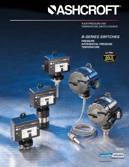
YOUR PRESSURE AND<br />
TEMPERATURE SWITCH SOURCE<br />
B-<strong>SERIES</strong> <strong>SWITCHES</strong><br />
PRESSURE<br />
DIFFERENTIAL PRESSURE<br />
TEMPERATURE<br />
BULLETIN SW-10<br />
A Halliburton Company
B-<strong>SERIES</strong><br />
PRODUCT<br />
INFORMATlON<br />
The Dresser Control Instrument<br />
Operation supplies highly reliable<br />
Ashcroft ® switches and controls for<br />
industrial and process applications. We<br />
begin with rock-solid designs, matching<br />
the most appropriate technology with<br />
the safety and reliability requirements of<br />
the applications. The materials of construction<br />
are specified to Dresser’s<br />
exacting standards, and product is built<br />
to last in the toughest applications. Our<br />
modern, responsive manufacturing facility<br />
in Milford, Connecticut is supported<br />
by an extensive network of stocking distributors<br />
and factory sales offices located<br />
in virtually every part of the world.<br />
Special application assistance is always<br />
just a telephone call away.<br />
The Ashcroft B-Series switch line is<br />
designed to satisfy most switch requirements.<br />
Materials of construction have<br />
been selected for long life. A wide variety<br />
of precision switch elements are<br />
available to meet every application<br />
requirement, including hermetically<br />
sealed contacts for added reliability and<br />
safety. The actuators we use have been<br />
proven in more than 20 years of service<br />
in the world’s plants and mills. Special<br />
designs are available for fire safety,<br />
NACE, limit control and other more<br />
stringent requirements. Simplicity and<br />
ease of use are stressed to improve<br />
reliability of the installation.<br />
B-Series switches have proven reliable<br />
in such harsh environments as:<br />
• Offshore oil rigs<br />
• Chemical and petrochemical plants<br />
• Pulp and paper mills<br />
• Steel mills<br />
• Power plants<br />
• Water and sewage-treatment plants<br />
• Other corrosive environments<br />
Type 400 Enclosure<br />
UL and CSA listed instrument<br />
quality snap-action switch for reliable<br />
operation. Ratings up to 10A dc or<br />
20A ac. Hermetically sealed switch<br />
also available.<br />
Epoxy-coated aluminum enclosure for<br />
corrosion resistance. Meets NEMA 3,<br />
4, 4X, 13 and IP66 requirements.<br />
Accessible adjustment for convenient<br />
switch setting, includes vibrationresistant<br />
feature.<br />
3<br />
⁄4 NPT electrical connection for<br />
easy wiring.<br />
Neoprene gasket for sealing<br />
enclosure.<br />
High proof pressure.<br />
Standard pressure connection materials:<br />
Pressure psi ranges – 316 SS<br />
Differential psid ranges – Nickel-plated brass<br />
Pressure and differential I.W. ranges –<br />
Epoxy-coated carbon steel<br />
Deadband limits for each switch.<br />
2
Applications include: pumps, compressors,<br />
washers, filters, degreasers,<br />
evaporators, recovery systems, food<br />
processing, ground support equipment,<br />
reverse osmosis systems, heat<br />
exchangers, hydraulic systems, lubrication<br />
systems, marine equipment, textile<br />
machinery, heating and air conditioning<br />
equipment.<br />
Hermetically Sealed Switch<br />
We recommend hermetically sealed<br />
switch elements for improved reliability.<br />
The hermetically sealed switch provides<br />
uncompromising contact protection in<br />
harsh or corrosive environments. The<br />
Ashcroft 400 Series is also approved<br />
for installation in Division II hazardous<br />
areas when supplied with hermetically<br />
sealed contacts.<br />
Features:<br />
• UL-recognized component, guide<br />
WSQ2, File E85076<br />
• All-stainless steel welded construction<br />
RECOMMENDED PRACTICE:<br />
All controls should be selected considering<br />
the media and ambient operating<br />
conditions. Improper application can<br />
be detrimental to the switch, cause<br />
failure and possibly personal injury<br />
or property damage.<br />
The information in this catalog is offered<br />
as a guide to assist in making the<br />
proper selection of Ashcroft controls.<br />
Additional information is available<br />
from Dresser Control Instrument<br />
Operations Sales. Offices are listed<br />
on the back cover.<br />
Type 700 Enclosure<br />
UL and CSA listed instrument<br />
quality snap-action switch for<br />
reliable operation. Ratings up to<br />
10A dc or 20A ac. Hermetically<br />
sealed switch also available.<br />
Dual (2 SPDT) shown.<br />
Epoxy-coated aluminum enclosure<br />
and cover for corrosion<br />
resistance. Class 1, Division 1 &<br />
2, Groups B, C, D, Class 2, Division<br />
1 & 2, Groups E, F, G,<br />
NEMA 7 & 9 and IP66.<br />
Terminal block wiring standard<br />
on dual switches. Optional<br />
(XK3) on single switches.<br />
Deadband limits for each switch.<br />
High proof pressure.<br />
Buna-N 0-ring for sealing<br />
enclosure.<br />
Two 3 ⁄4 NPT electrical conduit<br />
connections.<br />
Standard 316 SS pressure<br />
connection. Optional 1 ⁄2 NPT<br />
shown.<br />
Accessible adlustment is stainless<br />
steel for corrosion resistance,<br />
includes vibration-resistant feature.<br />
3
PRESSURE AND DIFFERENTlAL PRESSURE <strong>SWITCHES</strong><br />
B-Series pressure, differential pressure<br />
and vacuum switches use two different<br />
actuators depending on setpoint requirements.<br />
For setpoints between 2 and<br />
3000 psi, the simple, rugged diaphragmsealed<br />
piston actuator is used. This<br />
design features high reliability and<br />
choice of actuator seal materials for<br />
virtually every application. An optional<br />
welded design is also available for<br />
setpoints up to 1000 psi for maximum<br />
reliability. This design is available in<br />
PRESSURE/VACUUM <strong>SWITCHES</strong><br />
Overpressure Ratings<br />
Approximate Deadband (2) Switch Element<br />
Nominal Range (1) Proof psi Burst psi 20, 26, 27 21, 24, 31 50 22 32<br />
Vacuum<br />
–30˝ Hg –760mm Hg -100 kPa 250 400 0.3-0.7 1.5-3.0 0.5-2.2 0.4-1.5 2.1-4.2<br />
Compound<br />
–15˝ H2O/ –375mm H2O/ –3.7 kPa/ 20 35 0.15-75/ 1.5-2.5/ 0.45-2.0/ 0.5-1.2/ 2.1-3.5/<br />
15˝ H2O 375mm H2O 3.7 kPa 0.15-75 1.5-2.5 0.45-2.0 0.5-1.2 2.1-3.5<br />
–30˝ H2O/ –760mm H2O/ –7.5 kPa/ 20 35 0.30-60/ 1.5-2.5/ 0.45-2.0/ 0.5-1.5/ 2.1-3.5/<br />
30˝ H2O 760mm H2O 7.5 kPa 0.30-60 1.5-2.5 0.45-2.0 0.5-1.5 2.1-3.5<br />
–30˝ Hg/ –760mm Hg/ –100 kPa/ 0.5-1.0/ 2.0-3.0/ 0.75-2.5/ 0.7-1.8/ 2.8-4.2/<br />
15 psi 1.0 kg/cm 2 100 kPa 250 400 0.3-0.7 0.5-1.5 0 .5-1.0 0.7-1.4 0.7-2.1<br />
–30˝ Hg/ –760mm Hg/ –100 kPa/ 1.0-1.5/ 3.0-6.0/ 1.2-4.5/ 1.4-2.4 4.2-8.4/<br />
30 psi 2.0 kg/cm 2 200 kPa 250 400 0.3-0.8 1.0-2.0 0.7-1.5 0.4-1.3 1.4-2.8<br />
–30˝ Hg/ –760mm Hg/ –100 kPa/ 2.0-3.0/ 5.0-9.0/ 2.5-7.0/ 2.8-4.5 7.0-12.0/<br />
60 psi 4.0 kg/cm 2 400 kPa 250 400 0.7-1.5 3.0-5.0 1.1-4.0 1.0-2.3 4.2-7.0<br />
Pressure<br />
10˝ H2O 250mm H2O 2.5 kPa 20 35 0.2-0.5 1.0-2.0 0.35-1.5 0.4-1.0 1.4-2.8<br />
30˝ H2O 750mm H2O 7.5 kPa 20 35 0.3-0.6 1.5-2.5 0.45-2.0 0.5-2.0 2.1-3.5<br />
60˝ H2O 1500mm H2O 15 kPa 20 35 0.5-1.3 1.5-3.5 0.9-2.5 0.7-3.0 2.1-5.0<br />
100˝ H2O 2500mm H2O 25 kPa 20 35 0.6-1.6 2.5-5.5 1.1-4.0 1.0-4.0 3.5-7.7<br />
150˝ H2O 3750mm H2O 37 kPa 20 35 1.0-2.5 4.5-8.5 1.7-6.5 2.0-6.0 6.0-12.0<br />
15 psi 1.0 kg/cm 2 100 kPa 500 1500 0.1-0.35 0.5-1.5 0.2-1.0 0.4-1.0 0.7-2.1<br />
30 psi 2.0 kg/cm 2 200 kPa 500 1500 0.1-0.50 0.5-1.5 0.3-1.0 0.4-1.0 0.7-2.1<br />
60 psi 4.0 kg/cm 2 400 kPa 500 1500 0.3-1.0 1.0-3.5 0.7-2.5 0.6-2.0 1.4-5.0<br />
100 psi 7.0 kg/cm 2 700 kPa 1000 3000 0.5-1.7 1.5-5.0 1.1-3.5 1.0-4.5 2.1-7.0<br />
200 psi 14 kg/cm 2 1400 kPa 1000 3000 1-3 5-13 2-9 3.0-7.5 7.0-18.2<br />
400 psi 28 kg/cm 2 2800 kPa 2400 3000 4-7.5 5-24 5.5-15 4.0-11.0 7.0-33.6<br />
600 psi 42 kg/cm 2 4200 kPa 2400 3000 4-11 9-30 7-20 5.0-23.0 12.6-42<br />
1000 psi 70 kg/cm 2 7000 kPa 12000 18000 7-30 30-110 18-70 15-80 42-154<br />
3000 psi 210 kg/cm 2 2100 kPa 12000 18000 15-60 80-235 37-160 30.0-230 112-329<br />
PRESSURE/VACUUM <strong>SWITCHES</strong><br />
316 SS or Monel. Differential pressure<br />
models use a unique, dual diaphragmsealed<br />
piston design that features very<br />
high static operating pressures and<br />
small size.<br />
For setpoints between 4.5 and 150<br />
inches of H2O, a large diaphragm is<br />
used for increased sensitivity in both<br />
pressure and differential pressure<br />
designs with good choice of materials<br />
of construction.<br />
All standard models feature ±1 percent<br />
of range setpoint repeatability and a<br />
minimum of 400 percent of range proof<br />
pressures.<br />
These standard designs perform well in<br />
applications where shock and vibration<br />
could be a problem and may be used in<br />
conjunction with Ashcroft diaphragm<br />
seals in extreme services such as slurries<br />
or abrasive process fluids.<br />
Pressure Ratings<br />
Approximate Deadband (2) Switch Element<br />
Static Work-<br />
Nominal Range (1) ing Pressure Proof psi 20, 26, 27 21, 24, 31 50 22 32<br />
30˝ H2O 750mm H2O 7.5 kPa 5.4 21.6 0.3-0.6 1.5-2.5 0.45-2.0 0.5-2.0 2.1-3.5<br />
60˝ H2O 1500mm H2O 15 kPa 5.4 21.6 0.5-1.3 1.5-3.5 0.9-2.5 0.7-3.0 2.1-5.0<br />
100˝ H2O 2500mm H2O 25 kPa 5.4 21.6 0.6-1.6 2.5-5.5 1.1-4.0 1.0-4.0 3.5-7.7<br />
150˝ H2O 3750mm H2O 37 kPa 5.4 21.6 1.0-2.5 4.5-8.5 1.8-6.5 2.0-6.0 6.3-12.0<br />
15 psid 1.0 kg/cm 2 100 kPa 500 2000 0.5-1.0 2.0-5.0 0.7-3.5 0.7-1.4 2.8-7.0<br />
30 psid 2.0 kg/cm 2 200 kPa 500 2000 1.0-2.0 2.0-5.0 1.5-3.5 1.4-2.8 2.8-7.0<br />
60 psid 4.0 kg/cm 2 400 kPa 500 2000 2.0-4.0 3.0-6.0 3.0-4.5 2.8-5.6 4.2-8.5<br />
100 psid 7.0 kg/cm 2 700 kPa 1000 4000 4.0-10.0 11.0-20.0 7.0-15.0 6.0-14.0 16.0-28.0<br />
200 psid 14.0 kg/cm 2 1400 kPa 1000 4000 5.0-15.0 12.0-40.0 10.0-26.0 7.0-21.0 17.0-56.0<br />
400 psid 28.0 kg/cm 2 2800 kPa 1000 8000 10.0-20.0 20.0-60.0 15.0-40.0 14.0-28.0 28.0-84.0<br />
600 psid 42 0 kg/cm 2 4200 kPa 2000 8000 20.0-40.0 80.0-150.0 30.0-115.0 30.0-56.0 112.0-210.0<br />
Values shown are for zero static working pressure.<br />
4<br />
NOTES:<br />
1 Switches may generally be set between<br />
15% and 100% of nominal range on<br />
increasing pressure. Consult factory for<br />
applications where setpoints must be<br />
lower.<br />
2 All deadbands are given in English units<br />
as shown in the nominal range column.<br />
Deadbands shown are for switches with<br />
Buna N diaphragm. Approximate deadbands<br />
for optional diaphragms:<br />
Viton: Multiply Buna N value by 1.4<br />
Teflon: Multiply Buna N value by 1.2<br />
Stainless Steel: Multiply Buna N value by 1.7<br />
Monel: Multiply Buna N value by 1.7<br />
Dual Switch Element: Multiply single switch<br />
element value by 1.6 for approximate<br />
deadband.
ORDER INFORMATION<br />
B-<strong>SERIES</strong> PRESSURE AND DIFFERENTIAL PRESSURE SWITCH MODEL NUMBER:<br />
To specify the exact switch desired, select entries from appropriate tables as shown in example below.<br />
1 2 3 4 5<br />
B 4 2 0 B X P K 600 PSI<br />
B4<br />
B7<br />
D4<br />
D7<br />
1 – ENCLOSURE<br />
Pressure switch, type 400, watertight enclosure<br />
meets NEMA 3, 4, 4X, 13 and IP66 requirements.<br />
Pressure switch, type 700, explosion-proof<br />
enclosure meets Div. 1 & 2, NEMA 7, 9 and IP66<br />
requirements.<br />
Differential pressure switch, type 400, watertight<br />
enclosure meets NEMA 3, 4, 4X, 13 and<br />
IP66 requirements.<br />
Differential pressure switch, type 700, explosionproof<br />
enclosure meets Div. 1 & 2, NEMA 7, 9 and<br />
IP66 requirements.<br />
3 – ACTUATOR SEAL<br />
Range<br />
Code Process<br />
and Temperature Vac. 0-600 1000 3000<br />
Material Limits °F (9) ˝ H 2O psi psi psi<br />
B – Buna-N 0 to 150 • • • •<br />
V – Viton 20 to 300 • • •<br />
T – Teflon 0 to 150 • • • •<br />
S – 316L (8) 0 to 300 • •<br />
P – Monel (8) 0 to 300 • •<br />
NOTES:<br />
4 – OPTIONS<br />
Use table from page 9<br />
5 – RANGE<br />
Select from table on page 4<br />
1 Standard switch.<br />
2 Not available with psid ranges.<br />
3 Dual switches are 2 SPDT snap-action<br />
switches, not independently adjustable.<br />
4 Not available with type 400 enclosure.<br />
5 Not available with type 700 enclosure.<br />
6 Estimated dc. rating, 2.5A, 28 Vdc (not<br />
UL listed).<br />
7 Estimated dc rating, 0.4A, 120 Vdc (not<br />
UL listed).<br />
8 Available on pressure only.<br />
9 Ambient operating temperature limits –20<br />
to 150°F, all styles, setpoint shift of ±1% of<br />
range per 50°F temperature change is<br />
normal.<br />
2 – SWITCH ELEMENT SELECTION<br />
Order<br />
Switch Elements<br />
Code<br />
UL/CSA Listed SPDT<br />
20 (7) Narrow deadband ac 15A, 125/250 Vac<br />
21 Ammonia service 5A, 125/250 Vac<br />
22 (6) Hermetically sealed switch, 5A, 125/250 Vac<br />
narrow deadband<br />
23 Heavy duty ac 22A, 125/250 Vac<br />
24 (1) General purpose 15A, 125/250/480 Vac<br />
1<br />
⁄2A, 125 Vdc<br />
1<br />
⁄4A, 250 Vdc; 6A, 30 Vdc<br />
25 (2) Heavy duty dc 10A, 125 Vac or dc,<br />
1<br />
⁄8 HP, 125 Vac or dc<br />
26 (7) Sealed environment proof 15A, 125/250 Vac<br />
27 High temperature 300°F 15A, 125/250 Vac<br />
28 (5) Manual reset trip on 15A, 125/250 Vac<br />
increasing<br />
29 (5) Manual reset trip on 15A, 125/250 Vac<br />
decreasing<br />
31 Low level (gold) contacts 1A, 125 Vac<br />
32 Hermetically sealed switch, 11A, 125/250 Vac<br />
general purpose<br />
5A, 30 Vdc<br />
42 Hermetically sealed switch, 1A, 125 Vac<br />
gold contacts<br />
50 Variable deadband 15A, 125/250 Vac<br />
UL/CSA Listed Dual (2 SPDT)<br />
61 (7) Dual narrow deadband 15A, 125/250 Vac<br />
62 (7) Dual sealed environment 15A, 125/250 Vac<br />
proof<br />
63 Dual high temp. 300°F 15A, 125/250 Vac<br />
64 Dual general purpose 15A, 125/250/480 Vac<br />
1<br />
⁄2A, 125 Vdc<br />
1<br />
⁄4A, 250 Vdc<br />
65 Dual ammonia service 5A, 125/250 Vac<br />
67 (4,6) Dual hermetically sealed 5A, 125/250 Vac<br />
switch, narrow deadband<br />
68 (4) Dual hermetically sealed 11A, 125/250 Vac<br />
switch, general purpose 5A, 30 Vdc<br />
71 (4) Dual hermetically sealed 1A, 125 Vac<br />
switch, gold contacts<br />
5
TEMPERATURE <strong>SWITCHES</strong><br />
B-Series temperature switches feature<br />
a SAMA Class II vapor pressure thermal<br />
system. This system provides<br />
quick, accurate response to process<br />
temperature changes with negligible<br />
ambient temperature effects. This is<br />
inherent in the design due to the precise<br />
relationship that exists between<br />
temperature and pressure according to<br />
the vapor pressure laws. A wide selection<br />
of sensing bulb and armored capillary<br />
lengths is available. The vapor<br />
pressure system design features small<br />
bulb sizes, making installation easy and<br />
cost-effective.<br />
All models feature ±1.0% percent of<br />
span setpoint repeatability with very<br />
high overtemperature ratings.<br />
These standard designs perform well in<br />
applications where shock and vibration<br />
could be a problem and should be used<br />
with Ashcroft thermowells for bulb protection<br />
and ease of installation and<br />
maintenance.<br />
STANDARD TEMPERATURE RANGE SELECTION<br />
Nominal Range (1)<br />
Maximum<br />
Temperature<br />
Approximate Deadband (1) Switch Element<br />
°F °C °F 20, 26, 27 21, 24, 31 50 22 32<br />
–40 to 60 –40 to 160 400 1.0-2.0 3.0-8.0 1.5-5.5 1.4-6.0 8.0-16.0<br />
0 to 100 –20 to 400 400 1.5-3.0 5.0-12.0 2.2-8.5 1.5-7.5 9.0-20.0<br />
75 to 205 20 to 95 400 1.5-3.5 8.0-16.0 2.5-12.0 2.0-9.0 10.0-24.0<br />
150 to 260 65 to 125 400 1.5-3.0 5.0-12.0 2.2-8.5 2.0-9.0 10.0-24.0<br />
235 to 375 110 to 190 500 1.5-3.5 5.0-12.0 2.5-8.5 2.0-9.0 10.0-24.0<br />
350 to 525 (3) 175 to 275 700 2.0-4.5 8.0-16.0 3.2-12.0 2.5-10.0 15.0-34.0<br />
500 to 750 (2) 260 to 400 900 4.0-8.0 16.0-30.0 7.2-24.0 5.0-23.0 30.0-50.0<br />
NOTES:<br />
1 All deadbands given in °F.<br />
2 Available with remote mount thermal<br />
systems only.<br />
3 Not available with 2 3 ⁄4˝ stem.<br />
4 Dual switch element multiply single switch<br />
element value by 1.6 for approximate<br />
deadband.<br />
5 Set and reset points must fall within the<br />
adjustable range.<br />
THERMOWELLS<br />
Thermowells must be used on any<br />
application where the bulb of the temperature<br />
switch may be exposed to<br />
pressure, corrosive fluids or high<br />
velocity. Additionally, the use of a thermowell<br />
permits instrument interchange<br />
or calibration check without disturbing<br />
or closing down the process.<br />
Ashcroft temperature switches have<br />
bulb diameters to match 3 ⁄8˝ nominal<br />
bore thermowells Is. The bulbs have a<br />
sensitive portion length of 2˝ which can<br />
be used with 2 1 ⁄2˝ “U” dimensioned thermowells<br />
or longer. For maximum accuracy<br />
a thermowells “U” dimension<br />
should be selected to permit complete<br />
immersion of the sensitive portion plus<br />
1˝ when measuring the temperature of<br />
liquids; an extra 3˝ should be allowed<br />
when measuring the temperature<br />
of gases.<br />
Thermowell bushings should be used<br />
with remote mount temperature switches.<br />
We recommend the standard 3˝ bulb<br />
and code 69 Series bushings for use<br />
with any thermowell “U” dimension. A<br />
split rubber grommet allows easy installation<br />
and “S” dimension adjustment.<br />
To order a thermowell, refer to Price<br />
Sheet TH/PS-1 for complete information.<br />
69 series<br />
(XBX) bushing<br />
Bushing slides<br />
along capillary<br />
“S”<br />
INSTRUMENT (SWITCH)<br />
CONNECTION<br />
Process<br />
connection<br />
1/2" NPT<br />
“S”<br />
U˝<br />
3˝<br />
6
ORDER INFORMATION<br />
B-<strong>SERIES</strong> TEMPERATURE SWITCH MODEL NUMBER:<br />
To specify the exact switch desired, select entries from appropriate tables as shown in example below.<br />
1 2 3<br />
4<br />
T 4 2 0 T 0 5 030<br />
5<br />
X N H<br />
6<br />
150° to 260°F<br />
T4<br />
T7<br />
1 – ENCLOSURE<br />
Temperature switch, type 400, watertight enclosure<br />
meets NEMA 3, 4, 4X, 13 and IP66 requirements.<br />
Temperature switch, type 700, explosion-proof<br />
enclosure meets Div. 1 & 2, NEMA 7, 9 and IP66<br />
requirements.<br />
2 – SWITCH ELEMENT SELECTION<br />
Order<br />
Switch Elements<br />
Code<br />
UL/CSA Listed SPDT<br />
20 (7) Narrow deadband ac 15A, 125/250 Vac<br />
21 Ammonia service 5A, 125/250 Vac<br />
22 (6) Hermetically sealed switch, 5A, 125/250 Vac<br />
narrow deadband<br />
23 Heavy duty ac 22A, 125/250 Vac<br />
24 (1) General purpose 15A, 125/250/480 Vac<br />
1<br />
⁄2A, 125 Vdc<br />
1<br />
⁄4A, 250 Vdc; 6A, 30 Vdc<br />
25 (2) Heavy duty dc 10A, 125 Vac or dc,<br />
1<br />
⁄8 HP, 125 Vac or dc<br />
26 (7) Sealed environment proof 15A, 125/250 Vac<br />
27 High temperature 300°F 15A, 125/250 Vac<br />
28 (5) Manual reset trip on 15A, 125/250 Vac<br />
increasing<br />
29 (5) Manual reset trip on 15A, 125/250 Vac<br />
decreasing<br />
31 Low level (gold) contacts 1A, 125 Vac<br />
32 Hermetically sealed switch, 11A, 125/250 Vac<br />
general purpose<br />
5A, 30 Vdc<br />
50 Variable deadband 15A, 125/250 Vac<br />
UL/CSA Listed Dual (2 SPDT)<br />
61 (7) Dual narrow deadband 15A, 125/250 Vac<br />
62 (7) Dual sealed environment 15A, 125/250 Vac<br />
proof<br />
63 Dual high temp. 300°F 15A, 125/250 Vac<br />
64 Dual general purpose 15A, 125/250/480 Vac<br />
1<br />
⁄2A, 125 Vdc<br />
1<br />
⁄4A, 250 Vdc<br />
65 Dual ammonia service 5A, 125/250 Vac<br />
67 (4,6) Dual hermetically sealed 5A, 125/250 Vac<br />
switch, narrow deadband<br />
68 (4) Dual hermetically sealed 11A, 125/250 Vac<br />
switch, general purpose 5A, 30 Vdc<br />
71 Dual hermetically sealed 1A, 125 Vac<br />
switch, gold contacts<br />
3 – THERMAL SYSTEM SELECTION<br />
Direct Mount<br />
Order Code System Material Style<br />
TS 3l6 SS Rigid<br />
Remote Mount<br />
Order Code System Material Line Length Style (9)<br />
T05 316 SS 5´ Capillary<br />
T10 316 SS 10´ with<br />
T15 316 SS 15´ 302 SS<br />
T20 316 SS 20´ Spring<br />
T25 316 SS 25´ Armor<br />
4 – BULB LENGTH SELECTION<br />
Direct Mount<br />
Minimum<br />
Order “S” Thermowell<br />
Code Dimension “U” Dimension<br />
027 (8) 2 3 ⁄4˝ –<br />
040 4˝ 2 1 ⁄2˝<br />
060 6˝ 4 1 ⁄2˝<br />
090 9˝ 7 1 ⁄2˝<br />
120 12˝ 10 1 ⁄2˝<br />
Remote Mount<br />
030 (9) 3˝ 2 1 ⁄2˝<br />
6 – STANDARD TEMPERATURE<br />
RANGE SELECTION<br />
Adjustable Range<br />
°F °C<br />
–40 to 600 –40 to 160<br />
0 to 100 –40 to 400<br />
75 to 205 20 to 95<br />
150 to 260 65 to 125<br />
235 to 375 110 to 190<br />
350 to 525 175 to 275<br />
500 to 750 260 to 400<br />
NOTES:<br />
1 Standard switch.<br />
2 Available with remote mount<br />
thermal systems only.<br />
3 Dual switches are 2 SPDT<br />
snap-action switches, not<br />
independently adjustable.<br />
4 Not available with type 400<br />
enclosure.<br />
5 Not available with type 700<br />
enclosure.<br />
5 – OPTIONS<br />
Use table on<br />
page 9<br />
6 Estimated dc rating, 2.5A,<br />
28 Vdc (not UL listed).<br />
7 Estimated dc rating, 0.4A,<br />
120 Vdc (not UL listed).<br />
8 Not available on 350 to 525°F.<br />
9 Consult factory on remote<br />
mount for bulb lengths other<br />
than 3.˝<br />
7
OPTIONAL FEATURES AND ACCESSORIES<br />
XG9 – FIRE-SAFE WELDED<br />
ACTUATOR<br />
Standard features:<br />
• 3000 psi burst pressure unrestrained<br />
at room temperature<br />
• long service life<br />
• all welded – no O-rings<br />
• built-in over range protection<br />
• superior corrosion resistant<br />
materials<br />
• interchangeable with current<br />
Ashcroft pressure switch actuators<br />
• 15 psi to 600 psi ranges available<br />
The Ashcroft pressure switch actuator<br />
is designed to satisfy most medium<br />
range pressure switch applications. It<br />
has only two wetted parts; pressure port<br />
and diaphragm. No O-rings are required<br />
because all joints are welded.<br />
XG6 – U.L. LISTED LIMIT CONROL<br />
SWITCH<br />
Standard features:<br />
• setpoint indicating scale<br />
• adjusting nut stop<br />
• secondary chamber with vent<br />
• optional pilot light for FM<br />
requirements<br />
The Ashcroft medium pressure gas and<br />
oil limit control switch is designed for<br />
use with air, LP gas, natural gas, #1<br />
and #2 fuel oil and #6 oil preheated to<br />
240°F. This limit control is an adjustable<br />
pressure operated switch with a secondary<br />
chamber to prevent fuel from<br />
entering the switch enclosure in the<br />
unlikely event that the diaphragm<br />
develops a leak. The control shuts<br />
down a fuel pump in high or low pressure<br />
conditions.<br />
XG8 – U.L. LISTED STEAM LIMIT<br />
CONTROL SWITCH<br />
Standard features:<br />
• 316 stainless steel welded<br />
diaphragm<br />
• setpoint indicating scale<br />
• adjusting nut stop<br />
The Ashcroft steam limit control switch<br />
is designed for use on boilers equipped<br />
with electrically operated burners. The<br />
limit control is an adjustable pressure<br />
operated switch set to stop burner operation<br />
when the recommended safe boiler<br />
working pressure is exceeded.<br />
DIAPHRAGM SEALS<br />
Any of the complete line of Ashcroft<br />
diaphragm seals may be used with most<br />
Ashcroft switches. See Bulletin DS-1.<br />
8
OPTIONAL FEATURES AND ACCESSORIES<br />
B-<strong>SERIES</strong> SWITCH OPTIONS<br />
Appicable Switch Series<br />
Differential Temp-<br />
Pressure Pressure erature<br />
All<br />
Code Description (psi) (in. H2O) (psi) (in. H2O) Ranges Notes<br />
XBP Wall Mounting Bracket in. H 2O • •<br />
XBX 1 ⁄2˝ Male NPT Bushing •<br />
XCH Chained Cover • • • • •<br />
XC8 CSA Approval • • • • • 11<br />
XCN Cenelec EEx d IIC T6 • • • • •<br />
XFM FM Approval – Single Element • • • • 17<br />
FM Approval – Dual Element • • • • 17<br />
XFP Fungus Proofing • • • • •<br />
XFS Factory Adjusted Setpoint • • • • • 2<br />
XG3 Belleville Actuator • 16,17<br />
XG4 Teflon Actuator and Pressure Conn. • 8<br />
XG5 UL Limit Control to 150˝ H 2O • 1, 17<br />
XG6 UL Limit Control to 600 psi • 1, 17<br />
XG7 Secondary Chamber with Vent • 13<br />
XG8 Steam Limit Control to 300 psi • 7<br />
XG9 Fire Safe Welded Actuator • 7<br />
XHS High Static Diflerential Pressure • 15<br />
High Pressure, 40 psi, (static) DIP<br />
XHX 160 psi (proof) DIP • •<br />
100 psi proof pressure<br />
XJK Left Conduit Connection • • • • • 9<br />
XJL 3 ⁄4˝ to 1 ⁄2˝ Reducing Bushing • • • • •<br />
XK3 Terminal Block (700 Series only) • • • • • 6<br />
XL9 Low Hardness SS Press. Conn. • 12<br />
XNH Tagging Stainless Steel • • • • •<br />
XPK Pilot Light(s) Top Mounted • • • • • 4<br />
XPM 3 ⁄4˝ Sealed Conduit Connection<br />
with 16˝ Lead Wires • • • • •<br />
XTA 316 Stainless Steel Pressure<br />
Connection for in. H 2O Range<br />
• •<br />
XTM 2˝ Pipe Mounting Bracket • • • • •<br />
XUD 316 Stainless Steel Pressure Conn.<br />
•<br />
Pressure Connection:<br />
X06 1 ⁄2 NPT Male, 1 ⁄4 NPT Female • • • • 5<br />
316 Stainless Steel (Combination)<br />
X07 1 ⁄2 NPTF Press. Conn., 316 SS • • • • 10<br />
X2B Breather Drain • • • • •<br />
X6B Cleaned for Oxygen Service • • • 3<br />
Diaphragm Seal • • • •<br />
CENELEC APPROVAL FOR<br />
HAZARDOUS LOCATIONS<br />
CENELEC is a European designation that<br />
deals with standards for equipment and<br />
protective systems intended for use in<br />
potentially explosive atmospheres. This<br />
approval is required for switches intended<br />
for use in hazardous locations, especially<br />
important to OEMs who export to Europe<br />
and contractors specifying or purchasing<br />
products for European applications.<br />
XCN option adds special features to<br />
Ashcroft 700-Series switch enclosures<br />
that meet the requirements for the highest<br />
levels of security and danger,<br />
such as:<br />
• Special locking device requiring an Allen<br />
wrench to remove cover<br />
• Special vents that blow out should the<br />
diaphragm rupture, thus preventing<br />
pressure build-up in the enclosure<br />
• Special conduit plug requiring an Allen<br />
wrench for removal<br />
• Available on pressure, temperature and<br />
differential pressure models<br />
• Meets Explosion Class EEx d IIC T6<br />
Order option XCN<br />
NOTES:<br />
1 Buna N and Viton diaphragm.<br />
2 Advise static or working pressure for differential<br />
pressure switches.<br />
3 Buna N cannot be cleaned for oxygen service.<br />
4 N/A on 700 Series.<br />
5 Standard with 1000 and 3000 psi ranges. Bottom<br />
connection only on DIP in H 2 O ranges.<br />
6 Terminal Blocks standard with 700 dual switches.<br />
7 Stainless steel diaphragm only.<br />
8 Pressure connection 1 ⁄4 NPTF.<br />
9 Standard on 700 Series. N/A with DPDT<br />
element on 400 Series.<br />
10 N/A with Monel diaphragm.<br />
11 Standard on 400 Series.<br />
12 N/A on 3000 psi range. Available with Teflon<br />
diaphragm only.<br />
13 SS diaphragm required. Teflon diaphragm is the<br />
backup. NEMA 7 only.<br />
14 Available in ranges vacuum to 600 psi. Not<br />
available with stainless steel or Monel<br />
diaphragm.<br />
15 Buna N and Viton diaphragm – 15#D &<br />
30#D only.<br />
16 24, 32, 64 or 68 element only.<br />
17 N/A on all combinations<br />
9
PRODUCT SELECTION INFORMATION<br />
10<br />
SELECTION<br />
Before making your selection, consider the<br />
following:<br />
1. Actuator<br />
The actuator responds to changes in pressure,<br />
temperature or differential pressure<br />
and operates the switch element in response<br />
to these changes.<br />
The actuator is normally exposed to process<br />
fluid and must therefore be chemically compatible<br />
with it. The following may be used to<br />
help select actuator type:<br />
For nominal pressure ranges 0-15 psi<br />
through 0-3000 psi, Dresser’s standard actuator<br />
is a diaphragm-sealed piston. In this<br />
actuator, process pressure acting on the piston<br />
area causes it to overcome the adjustment<br />
spring force and actuate a snap-action<br />
switch. A diaphragm and O-ring seal the<br />
process media from this mechanism. These<br />
are available in various materials, i.e.: Buna<br />
N, Teflon and Viton. The standard process<br />
connection is stainless steel. Optional Monel<br />
pressure connection is available.<br />
For H 2O Pressure and Differential Pressure<br />
Ranges, a diaphragm actuator is used. In<br />
this design, the standard pressure connections<br />
are carbon steel. Diaphragms are available<br />
in Viton, Buna N and Teflon. Always<br />
review process temperature limits before<br />
making seal selections. Optional stainless<br />
steel pressure connections are available<br />
(option XTA).<br />
For High Differential Pressure Actuator<br />
Ranges, 3-15 to 60-600 psid, a Dual<br />
Diaphragm-Sealed Piston Actuator is used.<br />
This actuator is designed to for high staticpressure<br />
applications. The standard pressure<br />
connections are nickel-plated brass.<br />
Diaphragms are available in Viton, Buna N<br />
and Teflon. Always review process temperature<br />
limits before making seal selections.<br />
Optional stainless steel pressure connections<br />
are available (option XUD).<br />
For all temperature ranges the standard<br />
Ashcroft ® temperature actuator operates on<br />
the vapor pressure principle: the vapor pressure<br />
in a sealed thermal system is applied to<br />
a sensing element, which in turn actuates a<br />
switch. This is known as a SAMA Class II<br />
system. Various filling materials are used,<br />
including Propane, Butane, Methyl Alcohol,<br />
N Propyl Alcohol and Xylene. High overtemperature<br />
capability is possible with this type<br />
of system. The interface between liquid and<br />
vapor is the point at which sensing occurs.<br />
This is the “sensitive” portion of the bulb.<br />
Bulb extensions and capillary are normally<br />
filled with vapor, and have little effect on the<br />
setpoint, regardless of ambient temperature<br />
variations; therefore, no ambient compensation<br />
is required. For best results, the bulb<br />
should be mounted within 60 degrees of<br />
vertical to assure the liquid remains in<br />
the bulb.<br />
2. Enclosure<br />
The enclosure protects the switch element<br />
and mechanism from the environment and<br />
has provisions for mounting and wiring. All<br />
Ashcroft switch enclosures are epoxy-coated<br />
aluminum or stainless steel for maximum<br />
corrosion resistance. Choose between<br />
watertight NEMA 4, 4X for most industrial<br />
applications and explosion-proof NEMA 7/9<br />
for most process applications.<br />
Ashcroft enclosures include watertight cover<br />
gaskets, external mounting holes and one or<br />
two 3 ⁄4 NPT electrical conduit holes for ease<br />
of installation. Pressure switches may also<br />
be mounted directly to the process by<br />
means of the standard 1 ⁄4 NPTF or optional<br />
1<br />
⁄2 NPT pressure connection.<br />
Note: When installing Ashcroft switches,<br />
refer to instruction sheets included with<br />
each switch, the National Electrical Code,<br />
and any other local codes or requirements to<br />
assure safety.<br />
3. The Switching Function<br />
Next, consider the switching function. Most<br />
applications for alarm and shutdown are satisfied<br />
by single setpoint, fixed deadband<br />
models. For high/low or alarm and shutdown,<br />
the dual setpoint models may be<br />
selected. For pump, compressor, level and<br />
other control applications, an adjustable<br />
deadband model is often the best choice.<br />
Consult your Ashcroft representative for<br />
dual setpoint or adjustable-deadband pressure<br />
and temperature switches.<br />
4. The Switch Element<br />
Finally, the electrical switching element must<br />
be compatible with the electrical load being<br />
switched. For ease of selection, all electrical<br />
switching elements are snap acting, SPDT
PRODUCT SELECTION INFORMATION<br />
(single pole-double throw), or 2 (SPDT).<br />
Refer to catalog pages for switch element<br />
choices. Select a switch element with electrical<br />
rating that exceeds the electrical rating of<br />
the device being controlled by the switch.<br />
For better reliability and safety, optional<br />
Hermetically Sealed switching elements<br />
may be specified.<br />
ADDITIONAL SWITCH TERMINOLOGY<br />
Accuracy – (see repeatability) Accuracy normally<br />
refers to conformity of an indicated<br />
value to an accepted standard value. There is<br />
no indication in switch products; thus,<br />
instead, the term repeatability is used as the<br />
key performance measure.<br />
Automatic Reset Switch – Switch which<br />
returns to normal state when actuating variable<br />
(pressure or temperature) is reduced.<br />
Adjustable or Operating Range – That part<br />
of the nominal range over which the switch<br />
setpoint may be adjusted. Normally about<br />
15% to 100% of the nominal range for pressure<br />
and differential pressure switches and<br />
the full span for temperature switches.<br />
Burst Pressure – The maximum pressure<br />
that may be applied to a pressure switch<br />
without causing leakage or rupture. This is<br />
normally at least 400% of nominal range for<br />
Ashcroft switches. Switches subjected to<br />
pressures above the nominal range can be<br />
permanently damaged.<br />
Deadband – The difference between the setpoint<br />
and the reset point, normally<br />
expressed in units of the actuating variable.<br />
Sometimes referred to as differential.<br />
Division 1 – A National Electrical Code Classification<br />
of hazardous locations. In Division<br />
1 locations, hazardous concentrations of<br />
flammable gases or vapors exist continuously,<br />
intermittently or periodically under normal<br />
conditions; frequently because of repair or<br />
maintenance operation/leakage or due to<br />
breakdown or faulty operation of equipment<br />
or processes which might also cause simultaneous<br />
failure of electrical equipment.<br />
Explosion-proof NEMA 7/9 enclosures are<br />
required in Division 1 locations.<br />
Division 2 – A National Electrical Code Classification<br />
of Hazardous locations. In Division<br />
2 hazardous locations, flammable or volatile<br />
liquid or flammable gases are handled,<br />
processed or used, but will normally be confined<br />
within closed containers or closed systems<br />
from which they can escape only in<br />
case of accidental rupture or breakdown or<br />
in case of abnormal operation of equipment.<br />
Either Nema 7/9 explosion-proof enclosures<br />
or any enclosure with hermetically sealed<br />
switch contacts may be used in Division 2<br />
locations.<br />
Explosion Proof – A term commonly used<br />
in industry referring to enclosures capable of<br />
withstanding an internal explosion of a specified<br />
gas without igniting surrounding gases.<br />
Strict installation practices in accordance<br />
with the national electrical code are also<br />
required for safety.<br />
Fixed Deadband – The difference between<br />
the setpoint and the reset point of a pressure<br />
or temperature switch. It further signifies<br />
that this deadband is a fixed function of the<br />
pressure switch and not adjustable.<br />
Hermetically Sealed Switch – A switch element<br />
whose contacts are completely sealed<br />
from the environment to provide additional<br />
safety and reliability. Contact arc cannot<br />
cause an explosion, and atmospheric corrosive<br />
elements cannot affect the contacts.<br />
Manual Reset Switch – Pressure or Temperature<br />
switch in which contacts remain<br />
actuated even after the actuating variable<br />
returns to normal. On Ashcroft manual reset<br />
switches, a button must be pushed to reset<br />
the contacts.<br />
National Electrical Manufacturers Association<br />
(NEMA) – This group has defined several<br />
categories of enclosures, usually referred<br />
to as “types.” Further, they designate certain<br />
features and capabilities each type must<br />
include. For example, among other features,<br />
a NEMA 4 enclosure must include a threaded<br />
conduit connector, external mounting provision<br />
and cover gaskets. When selecting a<br />
NEMA 4 enclosure from any manufacturer, a<br />
buyer is assured of receiving these features.<br />
NEMA 4 – Watertight and dusttight enclosures<br />
intended for use indoors or outdoors<br />
to protect the equipment against splashing,<br />
falling or hose-directed water, external condensation<br />
and water seepage. They are also<br />
sleet-resistant.<br />
NEMA 4X – Watertight, dusttight and corrosion-resistant<br />
enclosures with same qualifications<br />
as NEMA 4, but with added corrosion<br />
resistance.<br />
NEMA 7 – Enclosures for indoor Class I,<br />
Division 1 Hazardous locations with gas or<br />
vapor atmospheres.<br />
NEMA 9 – Enclosures for indoor Class II,<br />
Division 1 Hazardous locations with combustible<br />
dust atmospheres.<br />
Normal Switch Position – Contact position<br />
before actuating pressure (or variable) is<br />
applied. Normally closed contacts open<br />
when the switch is actuated. Normally open<br />
contacts close when the switch is actuated.<br />
Normally Closed – Refers to switch contacts<br />
that are closed in the normal switch state or<br />
position (unactuated). A pressure change<br />
opens the contacts.<br />
Normally Open Switch – Refers to the contacts<br />
that are open in the normal switch<br />
state or position (unactuated). A pressure<br />
change closes the contacts.<br />
Overpressure Rating(s) – A nonspecific<br />
term that could refer to either burst or proof<br />
pressure, or both.<br />
Proof Pressure – The maximum pressure<br />
which may be applied without causing damage.<br />
This is determined under strict laboratory<br />
conditions including controlled rate of<br />
change and temperature: This value is for<br />
reference only. Consult factory for applications<br />
where switch must operate at pressures<br />
above nominal range.<br />
Repeatability (Accuracy) – The closeness of<br />
agreement among a number of consecutive<br />
measurements of the output setpoint for the<br />
same value of the input under the same<br />
operating conditions, approaching from the<br />
same direction, for full-range traverses.<br />
Note: It is usually measured as nonrepeatability<br />
and expressed as repeatability in percent<br />
of span or nominal range. It does not<br />
include hysteresis or deadband.<br />
Reset Point – The reset point is the Pressure,<br />
Temperature or Differential Pressure<br />
Value where the electrical switch contacts<br />
will return to their original or normal position<br />
after the switch has activated.<br />
Setpoint – The setpoint is the Pressure,<br />
Temperature or Differential Pressure value at<br />
which the electrical circuit of a switch will<br />
change state or actuate. It should be specified<br />
either on increase or decrease of that<br />
variable. (See also reset point.)<br />
Single-Pole Double Throw (SPDT) Switching<br />
Element – A SPDT switching element<br />
has one normally open, one normally closed,<br />
and one common terminal. The switch can<br />
be wired with the circuit either normally<br />
open (N/O) or normally closed (N/C). SPDT<br />
is standard with most Ashcroft pressure and<br />
temperature switches.<br />
Snap Action – In switch terminology, snap<br />
action generally refers to the action of contacts<br />
in the switch element. These contacts<br />
open and close quickly and snap closed with<br />
sufficient pressure to firmly establish an<br />
electrical circuit. The term distinguishes<br />
products from mercury bottle types that<br />
were subject to vibration problems.<br />
Static Pressure – For differential pressure<br />
switches, static pressure refers to the lower<br />
of the two pressures applied to the actuator.<br />
11
ADDITIONAL PRESSURE AND TEMPERATURE SWITCH<br />
APPLICATION INFORMATION<br />
DIFFICULT PROCESS MEDIA<br />
When specifying pressure or temperature<br />
switches, the material in contact with media<br />
must be compatible with it. Otherwise, failure<br />
could occur, resulting in leakage, injury,<br />
and loss of life, property or production. The<br />
user should review prior experience with<br />
materials of construction in the process for<br />
guidance in material selection. If this is not<br />
appropriate, contact Dresser’s Control<br />
Instrument Operation for assistance. Relevant<br />
information such as process media,<br />
concentration of each constituent, temperature,<br />
pressure, the presence of contaminants,<br />
particulate, vibration or pulsation is<br />
necessary to make the best recommendation.<br />
Refer also to Product Information Page<br />
ASH-PI-14B “Corrosion Data Guide.”<br />
Some applications are best handled by<br />
adding an Ashcroft diaphragm seal to isolate<br />
the fluid media from the pressure or differential<br />
pressure switch.<br />
Diaphragm seals are recommended where:<br />
• The process media being sensed could<br />
clog the pressure element.<br />
• The process media temperature is above<br />
or below the ratings of the actuator seal<br />
materials.<br />
• The application calls for a sanitary<br />
process connection.<br />
Note: The addition of a diaphragm seal may<br />
increase the deadband and response time of<br />
the pressure switch to process pressure<br />
changes. Please consult the Control Instrument<br />
Operation for details.<br />
Refer also to Ashcroft<br />
Product Bulletin DS-1<br />
and Product Information<br />
Page SW/PI-30B,<br />
“Switch, Diaphragm<br />
Seal Combination.”<br />
OXIDIZING MEDIA<br />
When specifying a<br />
pressure switch for<br />
use in oxidizing media,<br />
such as chlorine, oxygen<br />
and several other chemical compounds,<br />
the wetted materials must be compatible<br />
with the media, and the switch should be<br />
cleaned for oxygen service. This is necessary<br />
to remove any residue that might react<br />
violently with the oxidizing media. Specify<br />
option X6B (clean for oxygen service). Refer<br />
also to Product Information Page SW/PI-6B,<br />
“Oxygen Cleaning for Ashcroft Switches.”<br />
STEAM SERVICE<br />
In order to prevent live steam from coming<br />
into contact with the switch actuator, a<br />
siphon filled with water should be installed<br />
between the switch and the process line. We<br />
recommend the optional stainless steel<br />
welded process connection and diaphragm<br />
even though viton is rated for use with<br />
steam. Experience<br />
has<br />
shown that<br />
in many<br />
steam applications,<br />
the<br />
300°F high<br />
temperature<br />
limit of Viton<br />
is exceeded<br />
by steam<br />
under pressure.<br />
In some boiler applications, a special U.L.<br />
listing, “MBPR,” which requires unique features,<br />
is needed. Dresser offers these features<br />
with option XG8. Refer also to Product<br />
Information Page SW/PI-27A, “Steam Limit<br />
Control Switch.”<br />
NACE<br />
The National Associations of Corrosion<br />
Engineers (NACE) publishes a standard covering<br />
the requirements of metallic materials<br />
in contact with process media containing<br />
Hydrogen Sulfide. We recommend the use<br />
of Monel (code P) wetted materials for most<br />
applications. Other alternatives include<br />
adding applicable diaphragm seals or low<br />
hardness stainless steel pressure connection<br />
(XL9) and teflon diaphragm.<br />
Refer also<br />
to Product Information Page SW-22A,<br />
“Pressure Switches Meeting NACE<br />
Standard MR-01-75.”<br />
HIGH TEMPERATURE PROCESS<br />
Refer to the actuator seal table for<br />
process temperature limits for pressure<br />
switch actuators. Pressure switches<br />
mounted directly to the process can<br />
withstand up to 300°F when equipped<br />
with optional Viton, stainless steel or Monel<br />
wetted parts. If process temperature<br />
exceeds 300°F, four feet of 1 ⁄2˝ tubing<br />
between the process and the switch will<br />
generally protect the switch from damage.<br />
Alternatively, an Ashcroft diaphragm seal<br />
selected from bulletin DS-1 can be used to<br />
isolate the switch from the hot process.<br />
VIBRATION<br />
Generally, vibration will not harm Ashcroft<br />
pressure switches. However, premature tripping<br />
may occur under severe conditions.<br />
This tends to be annoying, but repeatable for<br />
a given situation and might be in the order of<br />
5% to 10% of switch range from the setpoint,<br />
i.e. a 100 psi switch set at 50 psi on<br />
increasing pressure might trip somewhere<br />
between 40 and 45 psi on increasing pressure.<br />
This would not reduce the life of the<br />
pressure switch.<br />
The best approach in this type of application<br />
is to mount the switch remotely, connecting<br />
the switch to the process or equipment with<br />
flexible tubing.<br />
If this is<br />
not possible,<br />
consider the<br />
use of the<br />
Belleville<br />
actuator,<br />
option XG3.<br />
Refer also to<br />
Product<br />
Information<br />
Page SW/PI-<br />
58,<br />
“Belleville<br />
Actuator.”<br />
PULSATION<br />
Pressure pulsation below the range of the<br />
pressure switch will not harm it. However,<br />
because the switch can react to pressure<br />
pulses less than one-second duration, it<br />
might be desirable to include a dampening<br />
device. Several Ashcroft accessories such as<br />
snubbers address this situation. Refer to the<br />
accessory section of Ashcroft Ordering<br />
Handbook (OH-1), or consult your Ashcroft<br />
representative for more information.<br />
MOUNTING<br />
All Ashcroft pressure, temperature and differential<br />
pressure switches with snap acting<br />
contacts may be mounted in any position.<br />
This includes the sensing bulbs of temperature<br />
switches. This is an important advantage<br />
of snap acting switch designs.<br />
12
ADDITIONAL PRESSURE AND TEMPERATURE SWITCH<br />
APPLICATION INFORMATION<br />
SWITCH ELEMENT SELECTION<br />
B-Series switches are available with a wide<br />
variety of snap acting switch elements to<br />
meet most electrical requirements. The standard<br />
contact arrangement is single pole,<br />
double throw (S.P.D.T.). This includes both<br />
normally open and normally closed contacts.<br />
Standard contact material is fine silver<br />
which generally is suitable for switching 8<br />
volts or more, up to the rating in the Switch<br />
Element Selection Table. When switching<br />
less than 8 volts, optional Gold Alloy contacts<br />
are recommended.<br />
Optional dual, or 2 S.P.D.T. contacts may be<br />
supplied in B-Series enclosures for applications<br />
requiring two switch functions at the<br />
same setpoint. These contacts are technically<br />
not double pole, double throw (D.P.D.T.).<br />
They are synchronized at the factory to actuate<br />
within 1% of nominal range of each<br />
other. For simultaneous actuation of 2<br />
S.P.D.T. contacts, option XG3 should be<br />
ordered. Refer also to SW/PI-58 “Belleville<br />
Actuator.”<br />
HAZARDOUS LOCATIONS<br />
a. Division I.<br />
Ashcroft 700 series or other explosion<br />
proof enclosures are<br />
required to meet the<br />
requirements of<br />
Division I Hazardous<br />
Locations<br />
as defined<br />
by the National<br />
Electrical Code.<br />
b. Division II.<br />
These enclosures also<br />
meet the less stringent requirements for<br />
Division II Hazardous Locations. Alternatively,<br />
Ashcroft 400 series or other<br />
watertight enclosures with hermetically<br />
sealed switch elements are approved for<br />
use in Division II hazardous locations.<br />
c. Intrinsic Safety.<br />
Ashcroft 400 and 700 series pressure<br />
and temperature switches may be used<br />
with approved barriers in most intrinsically<br />
safe systems. These switches do<br />
not create or store energy and are therefore<br />
designated “simple devices’’ in<br />
these systems.<br />
INFORMATION & GUIDELINES<br />
FOR SETTING ASHCROFT PRESSURE,<br />
TEMPERATURE AND DIFFERENTIAL<br />
PRESSURE <strong>SWITCHES</strong><br />
All Ashcroft pressure, temperature and differential<br />
pressure switches can be set at any<br />
point between about 15% and 100% of the<br />
range as designated on the label or the nominal<br />
range table.<br />
Ashcroft pressure and temperature switches<br />
can be either set in the field or ordered from<br />
the factory preset to your requirements.<br />
When set at the factory, the specification is<br />
±1% of the nominal range.<br />
Factory setting, or XFS, is a very popular<br />
option, and as a result, we often receive<br />
orders that do not have enough information<br />
or have incorrect information.<br />
HOW TO ORDER<br />
When “XFS” is desired:<br />
1. Setpoint must be indicated.<br />
2. Increasing or decreasing pressure must<br />
be indicated.<br />
Ex: B424B XFS 100#<br />
Set: 60# decreasing<br />
3. For differential pressure switches, static<br />
operating pressure must also be specified.<br />
For other Ashcroft switch models request Ashcroft<br />
Bulletin, Switch Quick Guide QG-3<br />
All product information pages mentioned in this<br />
bulletin can be downloaded from our web site.<br />
www.dresser.com/instruments<br />
13
TYPE 400 DIMENSIONS<br />
Pressure switch – psi ranges<br />
Pressure switch – inches of water ranges<br />
A (X06)<br />
D<br />
B<br />
Ø 0.28<br />
(3 Holes)<br />
E<br />
I<br />
G<br />
A<br />
A<br />
D<br />
B<br />
Ø 0.28<br />
(3 Holes)<br />
H<br />
2.7 lb<br />
(1.2 kg)<br />
3/4 NPT<br />
H<br />
C<br />
3/4 NPT<br />
J<br />
C<br />
X06 Variation<br />
1/2 NPT Male &<br />
1/4 NPT Female<br />
F<br />
1/4 NPT<br />
Female<br />
G<br />
F<br />
E<br />
Ø 0.34<br />
(2 Holes)<br />
1/4 NPT<br />
Female<br />
Bracket When<br />
Required “XBP”<br />
Variation<br />
I<br />
K<br />
A B C D E F G<br />
A B C D E F G H I<br />
5 4 3 1 ⁄4 3 5 ⁄16 2 3 ⁄4 2 5 ⁄16 1 3 ⁄16<br />
(127) (102) (83) (84) (70) (59) (30)<br />
Differential pressure switch –<br />
psi differential ranges<br />
1.8 lb<br />
(.81 kg)<br />
5 11 ⁄16 4 3 1 ⁄4 3 5 ⁄16 5 1 ⁄8 2 38 ⁄49 5 7 ⁄16 2 7 ⁄8 2 3 ⁄4<br />
(144) (102) (83) (84) (130) (44) (138) (73) (70)<br />
Differential pressure switch –<br />
inches of water ranges<br />
A<br />
Ø 0.28<br />
(3 Holes)<br />
D<br />
B<br />
Ø 0.28<br />
(3 Holes)<br />
C<br />
E<br />
A<br />
D<br />
H<br />
2.7 lb<br />
(1.2 kg)<br />
F<br />
1/4 NPT<br />
High<br />
Pressure<br />
Inlet<br />
B<br />
3/4 NPT<br />
1/4 NPT<br />
Low Pressure<br />
Inlet<br />
G<br />
H<br />
1/4 NPT<br />
Female<br />
(DP Only)<br />
G<br />
F<br />
E<br />
C<br />
Ø 0.34<br />
(2 Holes)<br />
3/4 NPT<br />
1/4 NPT<br />
Female<br />
Bracket When<br />
Required “XBP”<br />
Variation<br />
I<br />
K<br />
J<br />
A B C D E F G<br />
5 3 1 ⁄4 3 5 ⁄16 2 5 ⁄16 2 3 ⁄4 7 1 ⁄8 2 5 ⁄16 3.6 lb<br />
(102) (83) (84) (59) (70) (181) (59) (1.6 kg)<br />
Temperature switch – direct mount<br />
A B C D E F G H I J<br />
5 11 ⁄16 4 3 1 ⁄4 3 5 ⁄16 5 1 ⁄8 2 38 ⁄49 1 2 3 ⁄4 2 7 ⁄8 5 7 ⁄16<br />
(144) (102) (83) (84) (130) (44) (25.4) (70) (73) (138)<br />
Temperature switch – remote mount<br />
B<br />
Ø 0.28<br />
(3 Holes)<br />
G<br />
H<br />
B<br />
Ø 0.28<br />
(3 Holes)<br />
G<br />
H<br />
A<br />
C<br />
I<br />
A<br />
C<br />
I<br />
14<br />
F<br />
D<br />
2.5 lb<br />
(1.1 kg)<br />
3/4 NPT<br />
7/8 Hex<br />
1/2 NPT Male<br />
2-5/16<br />
Active<br />
Bulb<br />
Length<br />
A B C D E F G H<br />
4 5 ⁄8 4 3 5 ⁄16 3 1 ⁄4 1 5 ⁄8 4 7 ⁄8 2 5 ⁄16 1 3 ⁄16<br />
(117) (102) (84) (83) (41) (124) (59) (30)<br />
“S”<br />
Ø 3/8<br />
E<br />
F<br />
D<br />
3/4 NPT<br />
A B C D E F G<br />
4 5 ⁄8 4 3 5 ⁄16 3 1 ⁄4 1 5 ⁄8 2 5 ⁄16 1 3 ⁄16<br />
(117) (102) (84) (83) (41) (59) (30)<br />
2.31<br />
Active<br />
Bulb<br />
Length<br />
3.5 lb<br />
(1.6 kg)<br />
J<br />
Ø 3/8<br />
E “L”
FERMER<br />
MET TRE EN SERVICE.<br />
FERMER<br />
FERMER<br />
MET TRE EN SERVICE.<br />
FERMER<br />
MET TRE EN SERVICE.<br />
FERMER<br />
MET TRE EN SERVICE.<br />
MET TRE EN SERVICE.<br />
FERMER<br />
MET TRE EN SERVICE.<br />
TYPE 700 DIMENSIONS<br />
Pressure switch – psi ranges Pressure switch –<br />
inches of water ranges<br />
B<br />
0.28 THRU<br />
(3 PLACES)<br />
E<br />
F<br />
B<br />
0.28 THRU<br />
(3 PLACES)<br />
E<br />
F<br />
A<br />
CAUTION<br />
TO PREVENT IGNITION OF<br />
HAZARDOUS ATMOSPHERE TURN OFF<br />
TIGHTLY BEFORE OPERATING.<br />
POWER BEFORE OPENING. CLOSE<br />
DE<br />
AVANT<br />
AVANT<br />
COURANT<br />
LE<br />
COUPER<br />
BIEN<br />
D’OUVRIR.<br />
CAUTION<br />
D<br />
3/4 NPT<br />
(2 PLACES)<br />
H<br />
A<br />
CAUTION<br />
C<br />
TO PREVENT IGNITION OF<br />
HAZARDOUS ATMOSPHERE TURN OFF<br />
TIGHTLY BEFORE OPERATING.<br />
POWER BEFORE OPENING. CLOSE<br />
DE<br />
AVANT<br />
AVANT<br />
COURANT<br />
LE<br />
COUPER<br />
BIEN<br />
D’OUVRIR.<br />
CAUTION<br />
D<br />
H<br />
3/4 NPT<br />
(2 PLACES)<br />
1/4 NPT<br />
FEMALE<br />
C<br />
I<br />
2.7 lb<br />
(1.2 kg)<br />
A B C D E F G H I<br />
5 47 ⁄64 5 13 ⁄16 4 3 ⁄8 3 7 ⁄8 3 31 ⁄32 1 7 ⁄32 2 5 ⁄16<br />
G<br />
5<br />
⁄16 1 5 ⁄16<br />
(146) (132) (111) (99) (100) (31) (59) (8) (49)<br />
J<br />
I<br />
3.6 lb<br />
(1.6 kg)<br />
1/4 NPT<br />
FEMALE<br />
A B C D E F G H I J<br />
6 7 ⁄16 5 13 ⁄64 4 3 ⁄8 3 29 ⁄32 3 31 ⁄32 1 7 ⁄32 5 5 ⁄8 3 29 ⁄32 5 5 ⁄8 2 25 ⁄32<br />
(164) (132) (111) (99) (96) (31) (59) (8) (130) (71)<br />
G<br />
BRACKET WHEN<br />
REQUIRED “XBP”<br />
VARIATION<br />
Differential pressure switch –<br />
psi differential ranges<br />
Differential pressure switch –<br />
inches of water ranges<br />
B<br />
0.28 THRU<br />
(3 PLACES)<br />
E<br />
F<br />
B<br />
0.28 THRU<br />
(3 PLACES)<br />
E<br />
F<br />
A<br />
CAUTION<br />
C<br />
TO PREVENT IGNITION OF<br />
HAZARDOUS ATMOSPHERE TURN OFF<br />
TIGHTLY BEFORE OPERATING.<br />
POWER BEFORE OPENING. CLOSE<br />
DE<br />
AVANT<br />
AVANT<br />
COURANT<br />
LE<br />
COUPER<br />
BIEN<br />
D’OUVRIR.<br />
CAUTION<br />
D<br />
3/4 NPT<br />
(2 PLACES)<br />
H<br />
1/4 NPT<br />
FEMALE<br />
(DP ONLY)<br />
A<br />
CAUTION<br />
C<br />
TO PREVENT IGNITION OF<br />
HAZARDOUS ATMOSPHERE TURN OFF<br />
TIGHTLY BEFORE OPERATING.<br />
POWER BEFORE OPENING. CLOSE<br />
DE<br />
AVANT<br />
AVANT<br />
COURANT<br />
LE<br />
COUPER<br />
BIEN<br />
D’OUVRIR.<br />
CAUTION<br />
D<br />
H<br />
3/4 NPT<br />
(2 PLACES)<br />
1/4 NPT HIGH<br />
PRESSURE<br />
INLET<br />
1/4 NPT<br />
LOW PRESSURE<br />
INLET<br />
4.5 lb<br />
(2.0 kg)<br />
A B C D E F G H<br />
7 25 ⁄32 5 13 ⁄64 4 3 ⁄8 3 7 ⁄8 3 31 ⁄32 1 7 ⁄32 2 5 ⁄16<br />
(198) (132) (111) (99) (100) (31) (59) (8)<br />
5<br />
⁄16<br />
G<br />
J<br />
I<br />
3.6 lb<br />
(1.6 kg)<br />
1/4 NPT<br />
FEMALE<br />
A B C D E F G H I J<br />
6 7 ⁄16 5 13 ⁄64 4 3 ⁄8 3 29 ⁄32 3 31 ⁄32 1 7 ⁄32 5 5 ⁄8 3 29 ⁄32 5 5 ⁄8 2 25 ⁄32<br />
(164) (132) (111) (99) (96) (31) (59) (8) (130) (71)<br />
G<br />
BRACKET WHEN<br />
REQUIRED “XBP”<br />
VARIATION<br />
Temperature switch – direct mount<br />
B<br />
0.28 THRU<br />
(3 PLACES)<br />
E<br />
F<br />
Temperature switch – remote mount<br />
B<br />
0.28 THRU<br />
(3 PLACES)<br />
E<br />
F<br />
A<br />
CAUTION<br />
TO PREVENT IGNITION OF<br />
HAZARDOUS ATMOSPHERE TURN OFF<br />
TIGHTLY BEFORE OPERATING.<br />
POWER BEFORE OPENING. CLOSE<br />
DE<br />
AVANT<br />
AVANT<br />
COUPER<br />
BIEN<br />
D’OUVRIR.<br />
CAUTION<br />
D<br />
H<br />
A<br />
CAUTION<br />
TO PREVENT IGNITION OF<br />
HAZARDOUS ATMOSPHERE TURN OFF<br />
TIGHTLY BEFORE OPERATING.<br />
POWER BEFORE OPENING. CLOSE<br />
DE<br />
AVANT<br />
AVANT<br />
COUPER<br />
BIEN<br />
D’OUVRIR.<br />
CAUTION<br />
D<br />
H<br />
COURANT<br />
LE<br />
COURANT<br />
LE<br />
3/4 NPT<br />
(2 PLACES)<br />
G<br />
3/4 NPT<br />
(2 PLACES)<br />
G<br />
J<br />
C<br />
3.7 lb<br />
(1.7 kg)<br />
7/8 HEX<br />
1/2 NPT<br />
MALE<br />
2.31 (59)<br />
ACTIVE<br />
BULB<br />
LENGTH<br />
I<br />
S<br />
0.379 (9)<br />
J<br />
C<br />
4.5 lb<br />
(2.0 kg)<br />
2.31 (59)<br />
ACTIVE<br />
BULB<br />
LENGTH<br />
I<br />
3.00 (76)<br />
0.379 (9)<br />
L<br />
A B C D E F G H I J<br />
5 15 ⁄64 5 13 ⁄64 4 3 ⁄8 3 7 ⁄8 3 31 ⁄32 1 7 ⁄32 2 5 ⁄16 5<br />
⁄16 1 5 ⁄16 2 7 ⁄16<br />
(133) (132) (111) (99) (100) (31) (59) (8) (33) (62)<br />
A B C D E F G H I J<br />
5 15 ⁄64 5 13 ⁄64 4 3 ⁄8 3 7 ⁄8 3 31 ⁄32 1 7 ⁄32 2 5 ⁄16 5<br />
⁄16 2 1 ⁄2 2 7 ⁄16<br />
(133) (132) (111) (99) (100) (31) (59) (8) (63) (62)<br />
15
Instrument Division Sales and<br />
Customer Service Locations<br />
U.S. Headquarters<br />
Control Instrument Operation<br />
Milford, Connecticut<br />
210 Old Gate Lane<br />
Milford, CT 06460<br />
Tel: (203) 878-5641<br />
Fax: (203) 877-8519<br />
U.S. Sales Offices<br />
Chicago, Illinois<br />
400 W. Lake Street<br />
Suite 318<br />
Roselle, IL 60172-3573<br />
Tel: (630) 980-9030<br />
Fax: (630) 980-9440<br />
Hartford, Connecticut<br />
1501 East Main Street<br />
Meriden, CT 06450-2860<br />
Tel: (203) 235-0450<br />
Fax: (203) 235-0593<br />
Houston, Texas<br />
3838 North Sam Houston<br />
Parkway East<br />
Suite 120<br />
Houston, TX 77032<br />
Tel: (281) 590-1092<br />
Fax: (281) 590-7100<br />
Los Angeles, California<br />
3931 MacArthur Blvd.<br />
Suite 202<br />
Newport Beach, CA 92660<br />
Tel: (949) 852-8948<br />
Fax: (949) 852-8971<br />
Mobile, Alabama<br />
851 South Beltline Highway<br />
Suite 402, 4th Floor<br />
Mobile, AL 36606<br />
Tel: (334) 473-1692<br />
Fax: (334) 473-1782<br />
Visit our web site<br />
www.dresser.com/instruments<br />
International Headquarters<br />
Stratford, Connecticut<br />
250 E. Main Street<br />
Stratford, CT 06614-5145<br />
Tel: (203) 378-8281<br />
Fax: (203) 385-0357<br />
International Operations<br />
Brazil<br />
Dresser Industria e<br />
Comercio Ltda.<br />
Divisao Manometros Willy<br />
Rua Senador<br />
Vergueiro No. 433<br />
09521-320 Sao Caetano do Sul<br />
Sao Paulo, Brazil<br />
Tel: 55-11-453-5477<br />
Fax: 55-11-453-8710<br />
Canada<br />
Dresser Canada, Inc.<br />
2135 Meadowpine Blvd.<br />
Mississauga,<br />
Ontario L5N 6L5<br />
Canada<br />
Tel: 905-826-8411<br />
Fax: 905-826-9106<br />
China<br />
Dresser Trading<br />
Room 2403, 24th Floor<br />
CITIC Bldg.<br />
19 Jianguo Menwai St.<br />
Beijing, P.R.C.<br />
Tel: 86-10-6500-3139<br />
Fax: 86-10-6512-0300<br />
France<br />
Dresser Europe GmbH<br />
Division Instrumentation<br />
74, Rue d’ Arceuil<br />
F-94578, Silic 265,<br />
France<br />
Tel: 33-01-49-79-22-59<br />
Fax: 33-01-46-86-25-24<br />
Germany<br />
Dresser Europe GmbH<br />
Postfach 11 20<br />
Max-Planck-Str. 1<br />
D-52499 Baesweiler<br />
Germany<br />
Tel: 49-2401-8080<br />
Fax: 49-2401-7027<br />
Japan<br />
Dresser Japan Inc.<br />
Room 318, Shin Tokyo Building<br />
3-1 Marunouchi 3-Chome,<br />
Chiyoda-ku, Tokyo, Japan<br />
Tel: 813-3201-1501/1506<br />
Fax: 813-3213-6567/6673<br />
Korea<br />
Dresser International S.A.<br />
Korea Office<br />
#2015 Kuk Dong Bldg.<br />
60-1, 3-KA, Choongmu-Ro,<br />
Chungku, Seoul, Korea 100-705<br />
Tel: 82-2-2274-079-2/3<br />
Fax: 82-2-2274-0794<br />
Mexico<br />
Dresser Instrument Division<br />
Henry Ford No. 114,<br />
Esq. Foulton, Fracc<br />
Industrial San Nicolas<br />
54030 Tlalnepantla edo<br />
de Mexico 54030<br />
Tel: 525-310-7217<br />
Fax: 525-310-2608<br />
Saudi Arabia<br />
Dresser Al Rushaid<br />
(DARVICO)<br />
P.O. Box 10145<br />
Jubail Industrial City<br />
Saudi Arabia 31961<br />
Tel: 966-3-341-0278<br />
Fax: 966-3-341-7624<br />
Singapore<br />
Dresser Singapore Pte Ltd.<br />
Instrument Operations<br />
Block 1004 Toa Payoh North<br />
#07-15/17<br />
Singapore 318995<br />
Tel: 65-252-6602<br />
Fax: 65-252-6603<br />
United Kingdom<br />
Dresser Europe GmbH<br />
East Gillibrands,<br />
Skelmersdale,<br />
Lancashire WN8 9TU<br />
United Kingdom<br />
Tel: 44-16-95-52600<br />
Fax: 44-16-95-52693<br />
Venezuela<br />
Manufacturas Petroleras<br />
Venezolanas S.A.<br />
KM 7 Carretera A<br />
El Mojan Calle 18,<br />
#15B355 ZONA<br />
Maracaibo Edo Zulia, Venezuela<br />
Tel: 58-61-579-762 or 070<br />
Fax: 58-61-579-461<br />
A Halliburton Company<br />
All specifications are subject to change without notice.<br />
All sales subject to standard terms and conditions.<br />
© Dresser Equipment Group, Inc. 20M CP 3P8/99