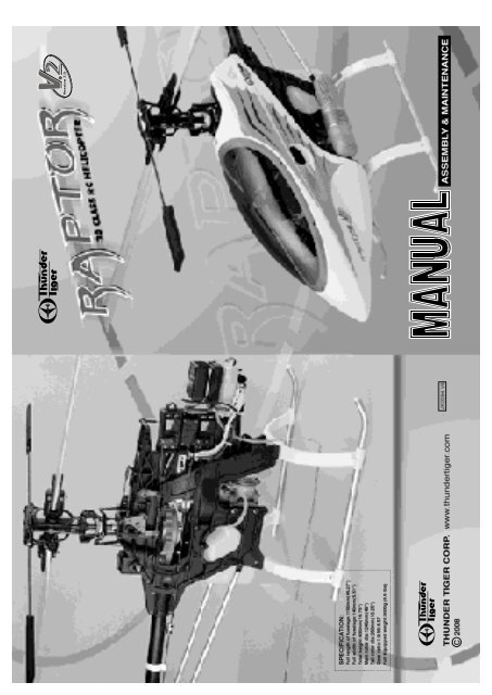
Raptor 30 V2 - DMT
Raptor 30 V2 - DMT
Raptor 30 V2 - DMT

You also want an ePaper? Increase the reach of your titles
YUMPU automatically turns print PDFs into web optimized ePapers that Google loves.
INTRODUCTION<br />
Congratulations on your purchase of the <strong>Raptor</strong> <strong>30</strong> <strong>V2</strong> helicopter. This model was designed and<br />
engineered by the World-renowned Mr. Shigetada Taya. It combines elements of his previously<br />
successful designs with today's advanced technologies. Since the introduction of the original<br />
<strong>Raptor</strong> <strong>30</strong> in 1998, many have been sold around the world. It is the most popular <strong>30</strong>-size helicopter<br />
in the world. The <strong>Raptor</strong> <strong>30</strong> has helped beginners master the art of RC helicopter flying. The<br />
<strong>Raptor</strong> <strong>30</strong> has helped experienced pilots learn new 3-D maneuvers. This is truly a versatile model<br />
helicopter for everyone. We did not just sat on our laurel, our team of engineers and test pilots<br />
have collected feedbacks from around the world and have now made the <strong>Raptor</strong> <strong>30</strong> an even better<br />
helicopter. We made new molds and tooling for new parts. Many area have subtle changes to<br />
increase strength and durability.<br />
As one of the largest R/C manufacturers in the world, Thunder Tiger has spared no expense to<br />
bring you this incredible new machine. All production parts are manufactured by use of the most<br />
modern technology available and meets or exceeds the standards as set forth by ISO-9001.<br />
In the last few years we have spend time and resource to develop a new Thunder Tiger PRO-<br />
39H(R) ring engine for the <strong>Raptor</strong> <strong>30</strong> <strong>V2</strong> and for other <strong>30</strong>-size helicopters. The new PRO-39H(R)<br />
has much better transition characteristics than the Pro 36H ABC engine. The needles are easy<br />
to set. The ring design eliminates the criticalness of ABC engines. You will find the new 39H<br />
engine produce more power than any other available <strong>30</strong>-size engines. Together, the new <strong>Raptor</strong><br />
<strong>30</strong> <strong>V2</strong> and the PRO 39H(R) engine will provide you with many hours of enjoyment. Thank you<br />
again for purchasing our fine products.<br />
CONTENTS<br />
Introduction......................................... p.1<br />
Contents..............................................p.1<br />
Warnings............................................. p.1<br />
Additional Items Needed.....................p.3<br />
Tools Needed...................................... p.3<br />
Assembling Section............................ p.4<br />
Flight Training Section........................ p.22<br />
Maintenance Section.......................... p.<strong>30</strong><br />
Blade Modification............................. p.35<br />
WARNING<br />
This radio controlled helicopter is not a toy. It is a sophisticated piece of equipment and<br />
is designed for hobby use only. If not properly assembled and operated, it is capable of<br />
causing property damage and bodily harm to both the operator and/or spectators. Thunder<br />
Tiger and its duly authorized distributors assume no liability for damage that could occur<br />
from the assembly and/or use/misuse of this product.<br />
AMA INFORMATION<br />
Operating a model helicopter requires a high degree of diligence and skill. If you are a<br />
newcomer to the hobby, it is best to seek help and guidance from accomplished model<br />
helicopter pilots. This will greatly speed up the learning process and have you flying<br />
successfully in a reasonable time. We also would strongly urge you to join the Academy<br />
of Model Aeronautics. The AMA is a non-profit organization that provides its members<br />
1
with a liability insurance plan as well as monthly magazine entitled Model Aviation. All<br />
AMA charter aircraft clubs require all pilots to hold a current AMA sporting license prior<br />
to operation of their models at club fields. For further information, contact the AMA at:<br />
Academy of Model Aeronautics<br />
5151 East Memorial Drive<br />
Muncie, IN 47<strong>30</strong>2<br />
(317) 287-1256<br />
FLIGHT SAFETY CHECKLIST<br />
1. Make sure both the transmitter and receiver batteries are fully charged prior to operation the<br />
helicopter.<br />
2. Make sure all flight controls operate properly prior to flying.<br />
3. Range check the radio before the first flight. The servos must operate properly with the<br />
transmitter antenna collapsed at a range of at least 50 ft.(15 meters).<br />
4. Check to make sure there is no radio interference on your radio channel before operating<br />
the helicopter.<br />
5. Use only the recommended engine fuel as specified by the engine manufacturer.<br />
6. Make sure the transmitter and receiver are turned on before starting the engine.<br />
7. The engine throttle must be in the idle position before starting the engine.<br />
8. Model helicopter main and tail rotors operate at high RPM. Make sure nothing can come in<br />
contact with the rotor blades during flight.<br />
9. After starting the helicopter, maintain a safe distance during the flight.<br />
10. Never operate the helicopter in rain or excessive wind conditions.<br />
11. Always operate and fly your helicopter in a safe and responsible manner.<br />
12. Never fly a model helicopter over other pilots, spectators or cars.<br />
POST FLIGHT INSPECTION<br />
1. Inspect the model thoroughly to insure no parts have come loose or become damaged during<br />
the flight and landing. Replace damaged parts and tighten loose screws before flying again.<br />
2. Pump out any remaining fuel from the fuel tank.<br />
3. Wipe off excess oil and fuel from helicopter body and other exposed parts.<br />
4. Lubricate all moving parts ensure smooth operation for the next time you fly.<br />
5. Store model in a cool, dry place. Avoid storage in direct sunlight or near a source of heat.<br />
Following these few, simple safety rules will allow you to enjoy the thrill of model helicopter flying<br />
for many years to come.<br />
2
RADIO SET<br />
OTHER ITEMS REQUIRED<br />
Receiver<br />
Battery<br />
1000mAh<br />
Switch harness<br />
Transmitter<br />
(helicopter type only<br />
6 or more channels)<br />
Servo x 5<br />
Gyro<br />
ENGINE<br />
Glow Fuel(15%-<strong>30</strong>%)<br />
12V Electric starter<br />
Glow Plug<br />
Extended 6mm Hex<br />
HELI ENGINE(39-size)<br />
Fuel Pump<br />
Starting Tool<br />
12V Battery<br />
1.5V Glow starter<br />
(1.2V~1.5V)<br />
Rubber Band<br />
Foam<br />
Training Gear<br />
Remote Glow Plug<br />
Extension<br />
(for beginners only)<br />
Screw Driver<br />
Glow Plug Wrench<br />
TOOLS REQUIRED FOR ASSEMBLY<br />
Needle Nose Pliers 5.5mm Wrench Ball Link Pliers Nipper Scissors<br />
7mm<br />
Metric<br />
4-way Wrench<br />
5.5mm<br />
7mm<br />
8mm<br />
Hobby Knife<br />
Instant Glue<br />
Blue Locktite<br />
Grease<br />
Epoxy<br />
Hex Wrench<br />
5.5mm<br />
7mm<br />
8mm<br />
10mm<br />
Socket Drivers<br />
3
ASSEMBLING SECTION<br />
The parts in the <strong>Raptor</strong> kit are packed according to the assembly steps. The part number and quantity contained<br />
in each are always shown in the square box on each page. Do not open all the bags at once. Open only the<br />
bag that is needed for the current assembly step.<br />
4
1 Fuel Tank Assembly<br />
Note: After assembly, check to make sure the Fuel Tank<br />
clunk can move from top to bottom without touching the<br />
back of tank. Also, a fuel filter (available from any hobby<br />
shop, TTR1164) should be placed between the fuel tank<br />
and the carburetor.<br />
To Engine<br />
(3 )BK0463<br />
(2 )BK0062<br />
(6) BB362-2<br />
(5 )CB0363-1<br />
(4 )BE1867<br />
(6) BB362-2<br />
To Muffler<br />
(1) BK0605 Fuel Tank .....................1<br />
(2)BK0062 Fuel Tank Grommet.......1<br />
(3)BK0463 Fuel Tank Nipple .......... 1<br />
(4)BE1867 Clunk.............................1<br />
(5)CB0363-1 Silicone Fuel Tube.....1<br />
(6)BB0362-2 Silicone Fuel Tube..... 2<br />
2 Clutch Bell Assembly<br />
(1) BK0605<br />
(1) HMV1680<br />
(1) HMV1680 Bearing (d8xD16xW5).....1<br />
(2) HMV1260Y Bearing (d6xD12xW4)...1<br />
(3) BK0591 Clutch Bell..........................1<br />
(4) BK0593 Drive Gear(Pinion).............1<br />
(5) BK0590 Clutch Liner........................1<br />
(4) BK0593<br />
(3) BK0591<br />
(2) HMV1260Y<br />
(5) BK0590<br />
The liner comes glued in the<br />
clutch bell already.<br />
5
3 Main Frame Assembly-Part1<br />
Please insert the frame spacers, bearings, pulley and parts in the frames according the drawing below. Tighten the<br />
screws snugly, but do not over torque them which could strip the plastic.<br />
Insert starter shaft through the center of the clutch bell assembly, through the top starter shaft bearing and into the<br />
starter coupling. Secure with the two set screws. Make sure this is tightly secured.<br />
(1) HSE3-12B Self Tapping Screw (M3x12).. <strong>30</strong><br />
(2) HMV696Z Bearing (d6xD15xW5).......... 1<br />
(3) HMV6800 Bearing (d10xD19xW5).......... 2<br />
(4) BK0059 Frame Spacer (S)....................... 8<br />
(5) BK0058 Frame Spacer (L)...................... 4<br />
(6) HME4-5B Set Screw (M4x5)................... 2<br />
(7) BK0081 Pin............................................. 2<br />
(8) BK0057 Servo Frame.............................. 1<br />
(9) BK0599 Main Frame Left Side.............. 1<br />
(10) BK0600 Main Frame Right Side..........1<br />
(11) BV0035 Guide Pulley.......................... 2<br />
(12) BK0036 Pulley Collar.......................... 4<br />
(13) BK0592 Starter Shaft.......................... 1<br />
(14) BK0594 Starter Coupling.................... 1<br />
(15) Fuel Tank Assembly<br />
(16) Clutch Assembly<br />
(17) HMS5 E-CLIP..................................... 1<br />
(18) BK0584 Thrust Washer.......................1<br />
(10) BK0600<br />
(14) BK0594<br />
(6) HME4-5B<br />
(3) HMV6800 Upper Main Shaft bearing<br />
(4) BK0059 Main Frame Spacer(S)<br />
(5) BK0058 Main Frame Spacer (L)<br />
(1) HSE3-12B<br />
(2) HMV696Z<br />
Top Starter Shaft<br />
Bearing<br />
(7) BK0081<br />
(12) BK0036<br />
(11) BV0035<br />
(1) HSE3-12B<br />
(8) BK0057<br />
(16) Clutch Bell<br />
Assembly<br />
(18) BK0584<br />
(17) HMS5<br />
(1) HSE3-12B<br />
(9) BK0599<br />
(13) BK0592<br />
(15) Fuel Tank Ass'y<br />
(3) HMV6800<br />
Lower Main Shaft Bearing<br />
6
4 Main Drive Gear Assembly<br />
(2) HMQ14<br />
(1) HMC3-12B Socket Screw (M3x12).......... 4<br />
(2) HMQ14 Snap Ring.................................... 2<br />
(3) BV0033 One Way Clutch Housing.............1<br />
(4) BK0031 Main Spur Gear........................... 1<br />
(5) BK0032 Tail Drive Pulley........................... 1<br />
(6) BK0034 One Way Clutch Shaft..................1<br />
(3) BV0033<br />
(4) BK0031<br />
(5) BK0032<br />
Add a drop of Blue Locktite on the<br />
thread of each of these four screws.<br />
(1) HMC3-12B<br />
(2) HMQ14<br />
(6) BK0034<br />
5 Washout Assembly<br />
(1) HMJ2-10N Self Tapping Screw(M2x10).. 2<br />
(2) HMC3-10B Socket Screw (M3x10)......... 2<br />
(3) HMV740ZZ Bearing (d4xD7xW2.5)........ 4<br />
(4) BK0077 Collar ........................................ 2<br />
(5) BK0079 Pin............................................. 2<br />
(6) BK0075 Linkage Ball.............................. 2<br />
(7) BK0015 Flybar Control Lever.................. 2<br />
(8) BK0016 Washout Linkage ..................... 2<br />
(9) BK0014 Washout Base............................1<br />
Make sure Linkage Balls are attached to the<br />
inside hole of each stabilizer control lever.<br />
(6) BK0075<br />
(2) HMC3-10B<br />
(4) BK0077<br />
(3) HMV740ZZ<br />
(7) BK0015<br />
(5) BK0079<br />
(1) HMJ2-10N<br />
(8) BK0016<br />
(3) HMV740ZZ<br />
(3) HMV740ZZ<br />
(9) BK0014<br />
(5) BK0079<br />
(3) HMV740ZZ<br />
(1) HMJ2-10N<br />
(8) BK0016<br />
(2) HMC3-10B<br />
(4) BK0077<br />
(6) BK0075<br />
(7) BK0015<br />
For sport kit (29BB) version, (3) will be replaced by Bushing(BK0107x4)<br />
7
6 Main Frame Assembly-Part2<br />
Add a drop of CA to the two screws at the pivoting point of the collective pitch control arm.<br />
Attach the linkage rod to the parallel elevator linkage balls.<br />
(1) HSE3-18B Self Tapping Screw(M3x18)....4<br />
(2) HSE3-12B Self Tapping Screw(M3x12)... 1<br />
(3) HMJ3-22B Self Tapping Screw(M3x22)....1<br />
(4) HMJ2-14N Self Tapping Screw(M2x14)... 1<br />
(5) HMJ2-10N Self Tapping Screw(M2x10)... 6<br />
(6) HMV1280 Bearing (d8xD12xW3.5)......... 2<br />
(7) HMV740ZZ Bearing (d4xD7xW2.5)........ 6<br />
(8) HMV840ZZ Bearing (d4xD8xW3)............ 2<br />
(9) BK0076 Collar......................................... 3<br />
(10) BK0078 Collar ...................................... 2<br />
(11) BK0088 Flat Washer ......................... 1<br />
(12) BK0084 Pin .......................................... 2<br />
(13) BK0075 Linkage Ball..............................8<br />
(14) BK0023 Elevator Control Arm Link........ 2<br />
(15) BK0018 Elevator Control Arm................ 1<br />
(16) BK0020 Elevator Arm Control Shaft.......1<br />
(17) BK0022 Aileron Control Lever................ 2<br />
(18) BK0019 Elevator Arm Parallel Lever...... 1<br />
(19) BK0086 Ball Link....................................2<br />
(20) BK0093 Linkage Rod ............................ 1<br />
(21) BK0021 Elevator Control Lever..............1<br />
(22) BK0017 Collective Pitch Control Arm.....1<br />
For sport kit (29BB) version,<br />
(7) will be replaced by Bushing(BK0107x6)<br />
(8) will be replaced by Bushing(BK0108x2)<br />
(5) HMJ2-10N<br />
(13) BK0075<br />
(12) BK0084<br />
(6) HMV1280<br />
(18) BK0019<br />
(21) BK0021<br />
(13) BK0075<br />
(1) HSE3-18B<br />
(5) HMJ2-10N<br />
(7) HMV740ZZ<br />
(9) BK0076<br />
(7) HMV740ZZ<br />
(1) HSE3-18B<br />
(19) BK0086<br />
(20) BK0093<br />
(14) BK0023<br />
(15) BK0018<br />
(14) BK0023<br />
(6) HMV1280<br />
(16) BK0020<br />
(1) HSE3-18B<br />
(5) HMJ2-10N<br />
(13) BK0075<br />
(9) BK0076<br />
(1) HSE3-18B<br />
(7) HMV740ZZ<br />
(17) BK0022<br />
(7) HMV740ZZ<br />
(2) HSE3-12B<br />
(10) BK0078<br />
(8) HMV840ZZ<br />
(5) HMJ2-10N<br />
(13) BK0075<br />
(22) BK0017<br />
(8) HMV840ZZ<br />
(10) BK0078<br />
(11) BK0088<br />
(7) HMV740ZZ<br />
66mm<br />
(3) HMJ3-22B<br />
(4) HMJ2-14N<br />
(9) BK0076<br />
(7) HMV740ZZ<br />
(13) BK0075<br />
Warning, do not over-torque the self-tapping screws.<br />
8
7 Main Frame Assembly-Part3<br />
Insert Main Shaft through the shaft bearings making sure that the end with the holes closest to the end is<br />
pointed down. Next, slide main gear assembly into position on the shaft and line up the holes in the main<br />
shaft with the holes in one way clutch shaft of the main gear assembly. Insert the socket head screw and<br />
secure with the lock nut. Next, slide on the mainshaft lock ring on top of the main shaft bearing and secure<br />
with the two set screws. Then slide on the swash plate assembly and attach the elevator and aileron<br />
control linkages to the outside swash plate linkage balls. Next, slide on washout assembly and attach<br />
washout linkage to the inner linkage balls of the swash plate.<br />
(1) BK0616 Socket Screw(M3x20)............1<br />
(2) HMM3Z Lock Nut (M3)........................ 1<br />
(3) HME4-5B Set Screw (M4x5)............... 2<br />
(4) BK0086 Ball Link ................................ 4<br />
(5) BK0092 Linkage Rod ......................... 2<br />
(6) BK00<strong>30</strong> Main Shaft Lock Ring............ 1<br />
(7) BK0029 Main Shaft ............................ 1<br />
(8) Wash Out Assembly<br />
(9) BV0601 Swash Plate Assembly...........1<br />
(10) Main Gear Assembly<br />
(4) BK0086<br />
(5) BK0092<br />
(4) BK0086<br />
(7) BK0029<br />
(8) Washout Assembly<br />
(9) BV0601<br />
(3) HME4-5B<br />
58mm<br />
(6) BK00<strong>30</strong><br />
(10) Main Gear Assembly<br />
8 Landing Skid Assembly<br />
(2) HMM3Z<br />
(1) BK0616<br />
(1) HSE3-18B Self Tapping Screw(M3x18).4<br />
(2) HME4-5B Set Screw(M4x5)..................4<br />
(3) BK0066 Skid Brace...............................2<br />
(4) BK0064 Skid Pipe.................................2<br />
(5) BK0065 Skid Pipe End Cap..................4<br />
(2) HME4-5B<br />
(3) BK0066<br />
(2) HME4-5B<br />
(3) BK0066<br />
(2) HME4-5B<br />
(5) BK0065<br />
(4) BK0064<br />
(5) BK0065<br />
(1) HSE3-18B<br />
9
9 Engine Assembly<br />
Note: A piston lock purchased from your dealer will make this a<br />
much easier task. You must replace the standard throttle arm<br />
w/the extended throttle arm and attach the linkage ball.<br />
(1) HMC3-10B Socket Screw(M3x10)..... 2<br />
(2) BV0589 Clutch Shoe..........................1<br />
(3) BV0038 Cooling Fan..........................1<br />
(4) No.9604 TT PRO-39H(R) Engine.......1<br />
(5) BK0170 Shim.....................................1<br />
(1) HMC3-10B<br />
(2) BV0589<br />
(5) BK0170<br />
(1) HMC3-10B<br />
Tighten the engine nut securely by<br />
grabbing the plastic fan with a towel.<br />
Linkage Ball to<br />
throttle Arm<br />
(3) BV0038<br />
Add Blue Locktite<br />
(4) No.9604<br />
10 Main Frame Assembly-Part4<br />
Add blue Loctite to all metal to metal screw surfaces.<br />
After installing the engine, connect the silicone fuel tube<br />
to the carburator and muffler.<br />
(1) HMC3-14B Socket Screw(M3xH)....... 8<br />
(2) HMC3-35B Socket Screw(M3x32)..... 2<br />
(3) BK0087 Flat Washer........................ 4<br />
(4) BK0037 Engine Mount........................ 1<br />
(5) No.9219 Muffler................................... 1<br />
(6) Engine Assembly<br />
(7) BA1578 Muffler Gasket.......................1<br />
(3) BK0087<br />
(1) HMC3-14B<br />
Add Blue Locktite<br />
(3) BK0087<br />
(3) BK0087<br />
(1) HMC3-14B<br />
Add Blue Locktite<br />
(3) BK0087<br />
(6) Engine Ass'y.<br />
(2) HMC3-35B<br />
(1) HMC3-14B<br />
10<br />
(4) BK0037<br />
(7) BA1578<br />
Engine mount<br />
Attachment<br />
(5) No.9219
11 Main Rotor Head Assembly<br />
Assembly Hint: Start from the bottom of the main Rotor Hub and work your way up to the flybar assembly. When<br />
screwing on the flybar paddles to the flybar, stop when you can see the rod in the window of the paddle. Then, lay<br />
the assembly on a flat surface and align the paddles so they are exactly parallel. Insert and tighten the set screws.<br />
Attach the flybar control rod to the flybar control arm and use the Double Link to connect the mixing lever (short<br />
side) to the Main rotor Pitch Housing.<br />
(1) HMC3-14B Socket Screw(M3x14)........... 2<br />
(2) HMC3-8B Socket Screw(M3x8)................ 2<br />
(3) HMJ2-10N Self Tapping Screw(M2x10).... 8<br />
(4) HME4-5B Set Screw(M4x5)...................... 2<br />
(5) HME3-10B Set Screw(M3x10).................. 2<br />
(6) BK0435 Washer (d4xD11xW1.7)............ 2<br />
(7) HMC4-8B Socket Screw (M4x8)............. 2<br />
(8) HMV8<strong>30</strong>ZZ Bearing (d3xD8xW4)............ 2<br />
(9) HMV740ZZ Bearing (d4xD7xW2.5)......... 4<br />
(10) HMV840ZZ Bearing (d4xD8xW3).......... 2<br />
(11) HMX0612 Thrust Bearing...................... 2<br />
For Sport kit (29BB) version,<br />
(9) will be replaced by Bushing(BK0107x4)<br />
(10) will be replaced by Bushing(BK0108x2)<br />
(18) BK0010<br />
(7) HMC4-8B<br />
(6) BK0435<br />
(12) HMV1360Z<br />
(5) HME3-10B<br />
(17) BK0067<br />
(3) HMJ2-10N<br />
(31) BK0075<br />
(22) BK0006<br />
(9) HMV740ZZ<br />
(13) BK0076<br />
(1) HMC3-14B<br />
(31) BK0075<br />
(9) HMV740ZZ<br />
(3) HMJ2-10N<br />
(16) BK0088<br />
(23) BK0596<br />
(11) HMX0612<br />
(32) BK0584<br />
(4) HME4-5B<br />
(19) BK0002<br />
(31) BK0075<br />
(12) HMV1360Z Bearing (d6xD13xW5).......... 4<br />
(13) BK0076 Collar.......................................... 2<br />
(14) BK0078 Collar.......................................... 2<br />
(15) BK0581 Flap Collar..................................2<br />
(16) BK0088 Flat Washer................................ 2<br />
(17) BK0067 Flybar Paddle............................ 2<br />
(18) BK0010 Flybar Rod..................................1<br />
(19) BK0002 Flybar Control Arm.................... 2<br />
(20) BK0005 Flybar Arm Bushing................... 2<br />
(21) BK0004 Flybar Seesaw Hub....................1<br />
(22) BK0006 Mixing Lever.............................. 2<br />
(<strong>30</strong>) BK0595<br />
(25) BK0007<br />
(26) BV0085<br />
(15) BK0581<br />
(25) BK0007<br />
(27) BK0586<br />
(29) BK0587 (28) BK0012<br />
(11) HMX0612<br />
Large Internal Diameteralways<br />
go toward the<br />
Main Rotor Hub<br />
(17) BK0067<br />
(22) BK0006<br />
(10) HMV840ZZ<br />
(14) BK0078<br />
(2) HMC3-8B<br />
(24) BK0583<br />
Small Internal Diameteralways<br />
go toward the<br />
Blade<br />
Diagram for Thrust Bearing Assembly<br />
11<br />
(23) BK0596 Main Rotor Pitch Housing........... 2<br />
(24) BK0583 Feathering Shaft................ 1<br />
(25) BK0007 Flybar Control Rod............. 2<br />
(26) BV0085 Double Link ...................... 2<br />
(27) BK0586 Flap Damper...................... 2<br />
(28) BK0012 Pin..................................... 2<br />
(29) BK0587 Main Rotor Hub Pin............1<br />
(<strong>30</strong>) BK0595 Main Rotor Hub.................. 1<br />
(31) BK0075 Ball Link............................. 8<br />
(32) BK0584 Thrust Washer.................... 2<br />
(5) HME3-10B<br />
(20) BK0005<br />
(8) HMV8<strong>30</strong>ZZ<br />
(21) BK0004<br />
(3) HMJ2-10N<br />
(31) BK0075<br />
(9) HMV740ZZ<br />
(13) BK0076<br />
(1) HMC3-14B<br />
(26) BV0085<br />
(12 ) HMV1360Z<br />
(3) HMJ2-10N<br />
(31) BK0075<br />
(23) BK0596<br />
(11) HMX0612<br />
(32) BK0584<br />
(12) HMV1360Z<br />
(6) BK0435<br />
(7) HMC4-8B
12 Main Frame Assembly-Part5<br />
Slide the main Rotor assembly over the main shaft and align the two pins to<br />
slide in the washout assembly. Make sure the holes in the main shaft line<br />
up with the holes in the main rotor head. Insert the socket screw and secure<br />
with locknut. Attach the ball linkage rods to the long end of the mixing lever<br />
and to the remaining inside linkage balls of the swash plate.<br />
(7) Main Rotor Head Ass'y.<br />
(1) BK0616 Socket Screw(M3x20)..... 1<br />
(2) HMM3Z Lock Nut(M3)........................1<br />
(3) HME3-18B Set Screw(M3x18)........... 2<br />
(4) BK0095 Linkage Rod......................... 2<br />
(5) BK0086 Ball Link............................... 4<br />
(6) BK0626 Canopy Retaining Post........ 2<br />
(7) Main Rotor Head Assembly<br />
(1) BK0616<br />
(4) BK0095<br />
(2) HMM3Z<br />
(6) BK0626<br />
(3) HME3-18B<br />
(5) BK0086<br />
(4) BK0095<br />
(5) BK0086<br />
100mm<br />
(3) HME3-18B<br />
(6) BK0626<br />
13 Tail Unit Assembly<br />
Assembly Tip: Work from left to right when assembling the parts. The tail pitch<br />
control lever screws into the arm extending from the tail unit housing.<br />
(1) HSE3-18B Self Tapping Screw(M3x18).1<br />
(2) HMC2610B Socket Screw(M2.6x10).....4<br />
(3) HSE2-10B Self Tapping Screw(M2x10).2<br />
(4) HMF2-8N Screw(M2x8).........................2<br />
(5) HME3-18B Set Screw(M3x18).............. 2<br />
(6) HMM3Z Lock Nut(M3)........................... 2<br />
(7) HMV1150X Bearing (d5xD11xW5)........ 1<br />
(8) HMV1050ZZO Angular Bearing (d5xD10x4)............ 4<br />
(9) HMV1060 Bearing (d6xD10xW3).......... 2<br />
(10) HMV740ZZ Bearing (d4xD7xW2.5).... 2<br />
(11) BK0082 Collar(2x3x4)......................... 2<br />
(12) BK0076 Collar(3x4x10)....................... 1<br />
(13) BK0083 Pin(2x9)................................. 2<br />
(14) BK0414 Pin(2x12)............................... 1<br />
(15) BK0088 Flat Washer............................1<br />
(16) BK0<strong>30</strong>2-1 Tail Pitch Housing (A)........ 2<br />
(17) BK0<strong>30</strong>3-1 Tail Pitch Housing (B)........ 2<br />
(18) BK0<strong>30</strong>7 Tail Rotor Hub....................... 1<br />
(19) BK0026 Tail Pitch Control Link........... 2<br />
(20) BK0025Tail Pitch Control Fork............ 1<br />
Red Side In<br />
Black Side Out<br />
Warning:<br />
Please note the assembling<br />
direction of the angular bearing.<br />
If they are not assembled properly<br />
as illustrated, they will easily fail<br />
and result in unexpected danger.<br />
(27) BK0047<br />
(7) HMV1150X<br />
(14) BK0414<br />
(24) BK0050<br />
(<strong>30</strong>) HME3-4B<br />
(21) BK0027 Tail Pitch Control Slider.................. 1<br />
(22) BK0028 Tail Pitch Control Slide Bushing..... 1<br />
(23) BK0053 Tail Rotor Shaft.............................. 1<br />
(24) BK0050 Tail Pulley....................................... 1<br />
(25) BK0051 Tail Pulley Flange...........................1<br />
(26) BK0024 Tail Pitch Control Lever.................. 1<br />
(27) BK0047 Tail Unit Housing (R)...................... 1<br />
(28) BK0075 Link Ball......................................... 2<br />
(29)HMM26B Lock Nut(M2).................................4<br />
(<strong>30</strong>)HME3-4B Set Screw(M3x4)...........................1<br />
(25) BK0051<br />
(10) HMV740ZZ<br />
(28) BK0075<br />
(4) HMF2-8N<br />
(3) HSE2-10B<br />
(11) BK0082<br />
(19) BK0026<br />
(20) BK0025<br />
(9) HMV1060<br />
(22) BK0028<br />
(23) BK0053<br />
(5) HME3-18B<br />
(8) HMV1050ZZO<br />
(16) BK0<strong>30</strong>2-1<br />
(29) HMM26B<br />
(28) BK0075<br />
(4) HMF2-8N<br />
(15) BK0088<br />
(10) HMV740Z<br />
(26) BK0024<br />
(12) BK0076<br />
(1) HSE3-18B<br />
For sport kit (29BB) version, (10)<br />
will be replaced by Bushing<br />
(BK0107x2)<br />
(6) HMM3Z<br />
(8) HMV1050ZZO<br />
(13) BK0083<br />
(29) HMM26B<br />
(17) BK0<strong>30</strong>3-1<br />
(2) HMC2610B<br />
(18) BK0<strong>30</strong>7<br />
(5) HME3-18B<br />
(6) HMM3Z<br />
(21) BK0027<br />
(2) HMC2610B<br />
(16) BK0<strong>30</strong>3-1<br />
12
14 Tail Boom Assembly<br />
Assembly Tip: Slide the 3 rod guides onto the boom and space them out evenly as shown. Then slide the tail linkage<br />
rod into the rod guides. Next, insert the tail rotor drive belt into the boom so that it comes out of both ends. Place<br />
drive belt over tail drive pulley and complete balance of tail boom assembly. Remember to connect the tail linkage<br />
rod to the tail control lever.<br />
(1) HMC3-20B Socket Screw(M3x20)..4<br />
(2) HMC3-25B Socket Screw(M3x25)..2<br />
(3) HSE3-12B Self Tapping Screw(M3x12).. 4<br />
(4) HMM3Z Lock Nut(M3).................... 6<br />
(5) HMV1150X Bearing (d5xD11xW5)..1<br />
(6) BK0046 Tail Unit Housing (L)..........1<br />
(7) BK0071 Vertical Fin........................ 1<br />
(8) BK0069 Stabilizer Fin..................... 1<br />
(9) BK0070 Stabilizer Fin Bracket........ 1<br />
(10) BK0540 Tail Support Rod..............2<br />
(11) BK0060 Tail Boom........................ 1<br />
(12) BK0091 Rod Guide........................3<br />
(13) BK0089 Tail Rotor Drive Belt... .....1<br />
(14) BK0100-2 Tail Linkage Rod.......... 1<br />
(15) BK0086 Ball Link.......................... 1<br />
(16) BV0052 Tail Idle Pulley................. 1<br />
(17) Tail Unit<br />
(18) HMJ2-8N Seif Tapping Screw(M2x8)..4<br />
(19) BK0447 Tail Support Rod End........... 4<br />
(13) BK0089<br />
(2) HMC3-25B<br />
(15) BK0086<br />
(8) BK0069<br />
(14) BK0100-2<br />
(12) BK0091<br />
(12) BK0091<br />
(11) BK0060<br />
(1) HMC3-20B<br />
(17) Tail Unit<br />
(10) BK0540<br />
(16) BV0052<br />
(3) HSE3-12B<br />
(9) BK0070<br />
(5) HMV1150X<br />
(6) BK0046<br />
(4) HMM3Z<br />
(7) BK0071<br />
(5) BK0068<br />
(4) HMM3Z<br />
(18) HMJ2-8N<br />
(19) BK0447<br />
15 Main Frame Assembly-Part6<br />
(1) HMC3-14B Socket Screw(M3x14)......2<br />
(2) HMC3-20B Socket Screw(M3x20)......4<br />
(3) HSE3-12B Self Tapping Screw(M3x12)....2<br />
(4) HMM3Z Lock Nut(M3)........................ 6<br />
(5) BK0068 Tail Rotor Blade.................... 2<br />
(6)Tail Assembly<br />
(5) BK0068<br />
(4) HMM3Z<br />
(6)Tail Ass'y<br />
(1) HMC3-14B<br />
(2) HMC3-20B<br />
Insert the four 3x20 socket screws into the tail base of the Main Frame<br />
and secure with lock nuts. Do not tighten at this point.<br />
Hold the tail boom in one hand and hook your index finger on your free<br />
hand through the exposed loop of the tail rotor drive belt. Hold it so the<br />
belt is vertical and parallel to the tail drive pulley.<br />
Boom Drive belt<br />
Important: Next, rotate the belt 90-degree counter clockwise.<br />
90-degree<br />
Pull the belt through the tail base, keeping the belt correctly aligned.<br />
Push the tail boom into the tail base all the way to the end. Place the<br />
drive belt over the tail drive spur gear. Then, gently pull back on the tail<br />
boom until the tension on the belt allows no more than 5mm(3/16") of<br />
free play in the belt. Tighten the locknuts and proceed with the rest of<br />
the assembly.<br />
(3) HSE3-12B<br />
(4) HMM3Z<br />
13
16 Servo Installation-Part1<br />
Assembly Tip: Remove all the servo wheels prior to attaching the steel linkage<br />
balls. Make sure all linkages are the correct length.<br />
(1) HSE2612N Self Tapping Screw(M2.6x12)....12<br />
(2) HMF2-8N Screw(M2x8)................................. 4<br />
(3) HML2 Hex Nut(M2)....................................... 4<br />
(4) HME4-5B Set Screw(M4x5).......................... 2<br />
(5) BK0093 Linkage Rod.................................... 2<br />
(6) BK0094 Linkage Rod..................................... 1<br />
(7) BK0100-1 Linkage Rod................................. 1<br />
(8) BK0105 Tail Control Rod Joint....................... 1<br />
(9) BK0075 Linkage Ball..................................... 4<br />
(10) BK0086 Ball Link......................................... 7<br />
Before installing Aileron Servo, tape the<br />
wire as shown.<br />
FUTABA<br />
(1) HSE2612N<br />
73mm<br />
Mount the Steel Linkage Balls at 10.5mm<br />
(approx 7/16") from the center of the servo<br />
horn.<br />
(9) BK0086<br />
(5) BK0093<br />
(2) HMF2-8N<br />
(1) HSE2612N<br />
Aileron Servo<br />
(4) HME4-5B<br />
(8) BK0105<br />
(7) BK0100-1<br />
(10) BK0086<br />
(6) BK0094<br />
Elevator Servo<br />
(1) HSE2612N<br />
Rudder Servo<br />
86mm<br />
(1) HSE2612N<br />
(2) HMF2-8N<br />
(1) HSE2612N<br />
(9) BK0075<br />
14
17 Servo Installation-Part2<br />
Assembly Tip: Remove all the servo wheels prior to attaching the steel linkage<br />
balls. Make sure all linkages are the correct length.<br />
(1) HSE2612N Self Tapping Screw(M2.6x12).... 8<br />
(2) HMF2-8N Screw(M2x8)................................ 3<br />
(3) HML2 Hex Nut(M2)...................................... 3<br />
(4) BK0075 Linkage Ball.................................... 3<br />
(5) BK0094 Linkage Rod .................................. 1<br />
(6) BK0092 Linkage Rod .................................. 1<br />
(7) BK0086 Ball Link.......................................... 4<br />
Mount the Steel Link<br />
Ball at 10.5mm(approx<br />
7/16") from the center<br />
of the servo horn.<br />
Pitch Servo<br />
51mm<br />
(7) BK0086<br />
(6) BK0092<br />
(3) HML2<br />
(4) BK0075<br />
(1) HSE2612N<br />
(2) HMF2-8N<br />
(3) HML2<br />
(4) BK0075<br />
(2) HMF2-8N<br />
Throttle Servo<br />
(1) HSE2612N<br />
(3) HML2<br />
(4) BK0075<br />
(2) HMF2-8N<br />
(7) BK0086<br />
(5) BK0094<br />
(1) HSE2612N<br />
75mm<br />
18 Receiver/Gyro Installation<br />
Thunder Tiger recognizes that there are many brands of radios and gyros to choose from. You are encouraged to<br />
seek the advice of experienced helicopter pilots when making this decision. We do recommend the use of the Thunder<br />
Tiger TG-8000 piezo Gyro since it was designed expressly for this machine.<br />
(1) BE1052 Antenna Tube................... 1<br />
(2) BK0106 Double Side Tape............ 2<br />
On/Off Switch Face Plate<br />
Thunder Tiger TG-8000 piezo<br />
gyro is recommended<br />
(2) BK0106<br />
On/Off Switch<br />
Gyro Amplifier<br />
(2) BK0106<br />
Receiver<br />
(2) BK0106<br />
Battery Pack<br />
(2) BK0106<br />
(1) BE1052<br />
15
19 Body/Canopy Assembly<br />
Cut off the bubble from the body leaving the lip all the way<br />
around. Neatness counts, so take your time. Next trim the<br />
flange from the canopy leaving a clean edge. You can lightly<br />
sand the edges to get it smooth and even. On the lip of the<br />
opening in the body, mark six points for drilling holes to secure<br />
canopy: 1-in front, 1-in rear and 2 on each side.<br />
Using double stick tape secure canopy to body. Take a very<br />
sharp awl and make pilot holes through the canopy and body<br />
lip. Make sure all holes line up. Remove double stick tape<br />
and put in the self tapping screws. Install the body clip, decals,<br />
and rubber grommets.<br />
(1) HMJ2-6B Self Tapping Screw(M2x4).. 6<br />
(2) HSE3-12B Self Tapping Screw(M3x12).... 2<br />
(3) BK0611 Body...................................... 1<br />
(4) BK0102 Rubber Grommet ................. 2<br />
(5) BK0098 Body Clip-A........................... 1<br />
(6) BK0099 Body Clip-B........................... 1<br />
(7) BK0612 Canopy.................................. 1<br />
(8)JV0093 Decal...................................... 1<br />
(1) HMJ2-6B<br />
(7) BK0612<br />
(1) HMJ2-6B<br />
(1) HMJ2-6B<br />
(4) BK0102<br />
(1) HMJ2-6B<br />
(4) BK0102<br />
(6) BK0099<br />
(5) BK0098<br />
(4) BK0611<br />
(2) HSE3-12B<br />
20 Main Rotor Assembly<br />
Important-While Thunder Tiger takes great care to manufacture the most balanced blades available, no two rotor<br />
blades are exactly the same. It is highly recommended that you purchase a blade balancer from your hobby dealer.<br />
Follow the manufacturers instructions for balancing the blades and install on helicopter.<br />
(1) BK0072 Main Rotor Blade.................2<br />
(2) HMD2612B Self Tapping Screw (M2.6x12)....... 2<br />
(3) BK0073 Upper Blade Grip... ............. 2<br />
(4) BK0074 Lower Blade Grip................ 2<br />
(5) HMM4Z Lock Nut(M4)...................... 2<br />
(6) HMC4-27B Socket Screw.................. 2 (1) BK0072<br />
(6) HMC4-27B<br />
(2) HMD2612B<br />
(3) BK0073<br />
(4) BK0074<br />
(5) HMM4Z<br />
16
Setting up Main Rotor Blades Pitch Angle<br />
*On the left side frame, there are<br />
three pitch scales molded onto<br />
the plastic frame. The three<br />
different scales are designed for<br />
beginner, intermediate or expert<br />
F3C and 3D pilots.<br />
*Use the "pointer" on the collective<br />
tray and the plastic molded scales<br />
to set up the initial collective<br />
control.<br />
*The actual blade angle in degrees<br />
can be checked using a pitch<br />
gauge (sold seperately).<br />
For Beginners<br />
For Intermediates<br />
For F3C or 3D<br />
Top End Pitch 12˚<br />
Hover 6˚<br />
Beginners 0˚<br />
Intermediates -4˚<br />
Pointer<br />
Bottem End Pitch -8˚<br />
(Hint for beginners)<br />
The hoveing pitch angle should be at 6˚. To get the 0˚ to 12˚<br />
collective range, mount the steel linkage ball at 10.5mm away<br />
from the center of the collective servo horn.<br />
FUTABA<br />
Mount the Steel<br />
Linkage Ball at<br />
10.5mm from the<br />
center of the servo<br />
horn.<br />
Throttle Stick in the center<br />
position<br />
6˚ hovering pitch angle is used for beginners, intermediates and experts. The throttle/collective must be<br />
in the center position when adjusting the collective pushrod length to make the "point" line up with the 6˚<br />
hover point on the molded scale(see above diagrams).<br />
17
*High End Blade Pitch Setting<br />
Linkage Position for beginner<br />
Throttle at High Position<br />
Move the throttle/collective stick to the full throttle position(see upper right diagram). The molded "pointer"<br />
should now line up with the upper limit mark, which should provide about 12˚ of blade pitch.<br />
*Low End Blade Pitch Setting<br />
Throttle at Low Position<br />
*Move the throttle/collective stick to the low stick position. Use the ATV function of your transmitter to make<br />
the "pointer" line up with the 0˚ mark for beginners(with the -4˚ mark for intermediates, and -8-degree<br />
mark for experts).<br />
18
Collective Travel for F3C and 3D Flying<br />
*To achieve +12˚ to -8˚ of collective travel range, the steel linkage ball must be moved to the inner<br />
location as shown in the figure.<br />
*Use ATV function of the transmittler to get the necesary servo travel.<br />
*High End Blade Pitch Setting<br />
Linkage Position for F3C or 3D<br />
Throttle at High Position<br />
The molded "pointer" should line up with the upper limit mark, which<br />
should provide about 12˚ of blade pitch.<br />
*Low End Blade Pitch Setting<br />
Position for F3C or 3D<br />
Throttle at Low Position<br />
For intermediates set the low end to -4˚. For advanced F3C and 3D flying,<br />
set the low end to -8˚.<br />
19
CONFIGURING THE RAPTOR FOR 3D<br />
5-Point Throttle Curves<br />
Normal 0 <strong>30</strong> 50 75 100<br />
Idle-up1 100 85 60 85 100<br />
Idle-up2 100 60 55 80 100<br />
<strong>30</strong>mm<br />
100mm<br />
5-Point Pitch Curves<br />
Normal 18 38 55 75 94<br />
Idle-up1 0 22 46 70 90<br />
Idle-up2 0 22 46 70 90<br />
Hold 15 38 55 75 100<br />
58mm<br />
use inner hole<br />
for beginner to 3D<br />
use outer hole<br />
for extreme 3D<br />
Blade Pitch Angles (degrees)<br />
Normal -4 5.5 9.5<br />
Idle-up1 -9 0 9<br />
Idle-up2 -9 0 9<br />
Hold -6 5.5 10.5<br />
10-12mm<br />
lengths<br />
measured from<br />
ball link center<br />
to<br />
ball link center<br />
58mm<br />
collective control<br />
for intermediates<br />
and 3D<br />
+10˚- –10˚<br />
54mm<br />
for beginnners<br />
51mm<br />
10mm<br />
make a 15˚ angle<br />
bend on tail rotor<br />
pushrod<br />
10mm<br />
The above pushrod lengths will permit 3D with the <strong>Raptor</strong>.<br />
Use these lengths as a starting point. Beginners can also use those pushrod lengths, but just connect the<br />
collective control to the outside point on the pitch control arm. Pushrod lengths are measured from ball link<br />
center to ball link center.<br />
Suggested throttle and collective pitch set up: Idle-up1 is used for continuous 3-D flips and aerobatics.<br />
Idle-up2 is used for switchless inverted hover. Use a pitch gauge to check blade angles. It is easier to start<br />
setting up idle-up2 blade pitch angles first. Beginners should inhibit idle-up1, idle-up2 and throttle hold.<br />
Beginners should only use the Normal mode values. The model should hover at around 1550 rpm in Normal<br />
mode, and flies at 1800 in idle-up1. Rotorspeed can be checked using TTR2000 MTF-<strong>30</strong>1 helicopter<br />
tachometer.<br />
20
Engine Throttle Control Linkage<br />
Mount the steel linkage ball to the outer hole on the metal throttle arm. At full throttle stick, the<br />
carburetor hole should open completely. At low throttle and with the throttle trim all the way down,<br />
the carburetor hole should close completely. Adjust the ATV function in your transmitter to achieve<br />
the above requirement. Listen to the servo, it should not make any binding noise. Try keep the<br />
throttle ATV between 90% and 110%. If your radio does not have ATV, then adjust the location<br />
of the steel link ball on the throttle servo horn to get the correct throttle travel.<br />
THROTTLE CLOSE<br />
THROTTLE FULLY OPEN<br />
21
FLIGHT TRAINING SECTION<br />
22
Preflight Adjustments<br />
Relationship between the control motion and radio transmitter.<br />
Always check all the controls to make sure they move<br />
in the correct direction and there is no mechanical<br />
binding or noise from the servos.<br />
23
Preflight Checklist and Starting Procedure<br />
(1) Check to make sure there is no radio interfence before operating the model helicopter.<br />
(2) Make sure the transmitter and receiver are on and all controls operate properly before flight.<br />
Range check the radio.<br />
(3) The engine carburetor must be in the idle position before starting the engine. Please read<br />
the engine instruction manual on how to properly adjust the engine. Set the carburetor main<br />
needle according to the engine instruction. Depending on the fuel and glow plug used, the<br />
carburetor idle screw may require fine adjustment of 1/4 to 1/2 turn away from the factory<br />
setting.<br />
(4) Fill the fuel tank, move the throttle stick to idle, and connect the glow plug battery to the glow<br />
plug.<br />
(5) Use a 12 volt electric starter along with<br />
a 6 mm hex starter extension (sold<br />
seperately) to start the engine.<br />
*A lw a ys g r ab on th e<br />
helicopter main rotor head<br />
when starting the engine.<br />
Otherwise, the main rotor<br />
may start spinning<br />
immediately after the<br />
engine is started.<br />
24
Flying Adjustments (1)<br />
Tracking adjustment ... When the two main rotor blades are in track it means their blade tips<br />
should follow the same path as they rotate.<br />
(1) Rev up the motor until the helicopter becomes<br />
light on its skids. Stand about 15 feet(4 meters)<br />
alway from the helicopter.<br />
(2) When the two main rotor blades are in<br />
track it means the blade tips should follow<br />
the same path as they rotate.<br />
increase<br />
throttle gently<br />
and not too<br />
much<br />
(3) When both blades are in track, the blade<br />
tips will appear to overlap as seen from<br />
the edge of the rotor plane.<br />
out of track<br />
If the blades are out of track, then adjust<br />
one of the pushrods that connects to the<br />
main rotor blade pitch arm.<br />
Redo steps (1) to (3) until<br />
the blades are tracking<br />
properly.<br />
in track<br />
In hover, the main blades should be<br />
around 5.5 to 6 degrees in pitch.<br />
25
Flying Adjustments (2)<br />
Trimming: All helicopters are inherently unstable. But when a helicopter is properly trimmed, it<br />
will not drift away or yaw by itself quickly. Use the following procedure to trim your<br />
helicopter.<br />
(1) If the helicopter nose starts to yaw left or right,<br />
then use the transmitter trim to compensate:<br />
yaw right<br />
yaw left<br />
(A) situation: move to (b)<br />
(B) situation: move to (a)<br />
(2) If the helicopter rolls to left or right, then:<br />
rolls right<br />
rolls left<br />
(C) situation: move to (d)<br />
(d) situation: move to (c)<br />
(3) If the helicopter noses down or up, then:<br />
Noses down<br />
Noses up<br />
(E) situation: move to (f)<br />
(F) situation: move to (e)<br />
26
Hover Training (1)<br />
Hovering is when the helicopter is floating in a stationary position in the air. Hovering is the<br />
fundamental manuever to learn first. Here is the procedure to practice hovering:<br />
(1) Make sure there are no spectators anywhere<br />
near the model helicopter. You, the pilot,<br />
should stand at least 10 meters (<strong>30</strong> feet)<br />
behind and slightly to the side of the model<br />
helicopter.<br />
(2) Prior to lifting off, while the main rotor is spinning and the helicopter is<br />
on the ground, check the main rotor fore/aft and left/right cyclic to make<br />
sure the main rotor is tilting in the correct direction according to your<br />
cyclic command. Move the tail rotor control stick to make sure the<br />
helicopter nose will swing in the desired direction.<br />
(3) Increase the throttle/collective to lift the model helicopter skids off the<br />
ground to no more than 10 cm(4 inches). Initially, it will be very difficult<br />
to control the model to prevent it from moving. For a beginner it will<br />
also be difficult to determine whether the helicopter is in trim or not.<br />
But with repeated practice close to the ground you will develop a feel<br />
for the controls. It is recommended to let a more experienced model<br />
helicopter pilot trim out your new model before you attempt to learn<br />
to hover.<br />
27
Hover Training (2)<br />
(1) It will take a few hours of hover practice with the helicopter skids at 10 to 20 cm (4-8 inches)<br />
off the ground in order to comfortably control the model.<br />
Do not try to lift the model to more than 10 to 20 cm(4-8 inches) in the beginning because<br />
then the model may tip over readily when the beginner panics and an incorrect command is<br />
given. Once you can keep the model in one place, then it is time to slowly increase the height<br />
by a few centimeters (inches) each flight. Soon, you will be able to hover the helicopter<br />
confidently a few feet high. Beginners should always practice hovering close to the ground<br />
because in an emergency, throttle and collective can be reduced rapidly without causing a<br />
large drop or damage to the model. If the model is hovering beyond one meter(3 feet) altitude,<br />
always descend slowly. A panic drop can damage the helicopter.<br />
(2) Always stand behind the model helicopter when learning how to hover. Then you can watch<br />
the nose of the helicopter. A left tail rotor command will yaw the helicopter nose to the left,<br />
and a right command will yaw to the right. Similarly, a left cyclic command will cause the<br />
helicopter to translate left. After you can comfortably hover the model at one meter high<br />
without drifting, then start practice hovering while standing to either side of the model.<br />
Eventually, you need to be comfortable at hovering<br />
the model from any orientation, including with<br />
the helicopter nose pointing at you. This is<br />
challenging because control directions are<br />
reversed.<br />
(3) Once you can confidently hover a model helicopter at any altitude and at any orientation,<br />
then congratulate yourself because you have mastered 80% of the fundamental control<br />
movements of a helicopter.<br />
28
Forward Flight Training<br />
After mastering hovering flight:<br />
(1) Start practicing moving the helicopter laterally to the left or right slowly from a 1.5 meter (60<br />
inches) high hover. This is the beginning exercise of translational flight.<br />
hovering at 1-1.5 meter<br />
(2) After a few hours of practicing step (1) and you are comfortable with translational movement,<br />
start using some tail rotor control so the helicopter nose will point slightly to the left or right as<br />
you fly it to the left or right. Eventually, this pattern will become a figure-eight in front of you.<br />
Please visualize<br />
these movements in your mind.<br />
29
MAINTENANCE SECTION<br />
<strong>30</strong>
After Flight Checklist<br />
(1) Check every screw and bolt to make sure none has loosened due to vibration.<br />
(2) Check every rotating and movable part to ensure they still move smoothly and<br />
normally.<br />
(3) Clean off the exhaust residue from the muffler, engine, and helicopter.<br />
(4) Check all movable parts, such as gears, ball links, belt, etc. for unusual wear.<br />
Trouble Shooting<br />
[1]The engine will not start.<br />
* The engine starting shaft will not turn:<br />
The engine may be flooded with too much fuel. Please remove the glow plug first, then turn the engine<br />
with the electric starter until the excess fuel spits out of the glow plug hole.<br />
* The engine turns when the electric starter is applied, but the engine will not start:<br />
(1) Is the glow plug working? Remove the glow plug and does the platinum coil glow red when a 1.5<br />
volt battery is applied to the plug? If not, then the glow plug battery may be weak and old.<br />
(2) Is the carburetor needle properly set? Please refer to the engine instruction manual for the proper<br />
needle setting.<br />
(3) Does the throttle control arm move properly and in the correct direction according your transmitter<br />
command?<br />
* Engine will start, but quits immediately.<br />
(1) Use the transmitter to increase the carburetor opening slightly. The throttle stick should never exceed<br />
the 1/3 positiom when starting the engine.<br />
(2) Try a new or different type of glow plug. There are different types of glow plugs on the market for<br />
different types of fuel and operating conditions. Seek the advice of experienced fliers and also<br />
experiment with different types of glow plugs until you find the one that suits your operating condition<br />
the best.<br />
*Engine runs, but the helicopter will not lift off.<br />
(1) Check the main rotor blade pitch angle, they should be set at 5.5 to 6 degrees when the transmitter<br />
throttle/collective stick is at the center position.<br />
(2) Does the engine throttle arm move properly? The carburetor opening should be fully open when<br />
the transmitter throttle/collective stick is moved up. The carburetor opening should be nearly closed<br />
when the transmitter throttle/collective stick is moved down. And the opening should be completely<br />
closed when the transmitter throttle/collective stick is moved down and the throttle trim is also<br />
moved down.<br />
(3) The carburetor needle is not set properly. Close the needle (turn it clockwise) all the way, then<br />
open the needle (turn it counter clockwise) 1 and 1/2 turns and try again. If the model still will not<br />
lift, then the engine maybe running too rich. If the symptom is the engine exhaust has a lot of<br />
smoke and the engine coughs and wants to quit when the transmitter throttle/collective stick is<br />
moved up, then close the needle 1/8 turn at a time, until the model will lift off. Do not turn the<br />
needle too far inward, that will make the engine run too lean and over-heat and damage the engine.<br />
[2] Helicopter problems.<br />
* The helicopter shakes.<br />
(1) Is the blade spindle bent?<br />
(2) Is the flybar bent?<br />
(3) Is the main rotor shaft bent?<br />
(4) Are the two control paddles mounted at the same distance from the rotor shaft, and the paddles<br />
are parallel to each other, and in the proper direction?<br />
(5) Is the tail rotor shaft bent? The tail rotor blades mounted properly or damaged?<br />
(6) Are the main rotor blades damaged or mounted in the proper orientation? The blades may require<br />
additional balancing. The blade balance can be checked by removing both blades and then use<br />
one of the 4mm blade bolt and nut to hold the two blades together like a teeter totter. Then, hold<br />
the blade bolt with your thumb and index finger. The two blades should teeter and remain in a<br />
level position. If not, then add some tape to the lighter blade near the blade tip until the two blades<br />
teeter in a level position. Hobby shops also sell blade balancers that are designed solely for<br />
balancing model helicopter blades.<br />
31
In the event the model has crashed.<br />
Inspect the flybar, rotor shaft and the blade spindle to make sure they are not bent at all. If any item is<br />
damaged, it must be replaced with a new part to ensure safe operation. Do not glue any broken or damaged<br />
plastic part. Do not repair broken rotor blades. Always inspect the following items immediately:<br />
Engine starting shaft.<br />
All the gears.<br />
Main shaft, flybar and blade spindle.<br />
Tail boom and support.<br />
Vertical and horizontal fins.<br />
Tail rotor shaft and control system.<br />
Main and tail rotor blades.<br />
Changing the main rotor shaft:<br />
(1) Disconnect the control rods to the washout arms.<br />
(2) Disconnect the washout link to the swashplate.<br />
(3) Loosen the set screws on the collar.<br />
(4) Remove the 3mm x 20 bolt.<br />
(5) Hold on to the plastic main gear and pull the 10mm<br />
main rotor shaft upward.<br />
(2)<br />
(3)<br />
(1)<br />
(1)<br />
(2)<br />
(3)<br />
(4)<br />
(1)<br />
(3)<br />
(2)<br />
Changing the blade feathering spindle:<br />
(1) Disconnect the linkage rods to the blade grips.<br />
(2) Remove the 4mmx8 bolt.<br />
(3) Pull out the blade grips gently.<br />
32
Changing the tail drive belt:<br />
(1)Loosen and remove all the necessary<br />
screws.<br />
(2)After installing the new belt, make sure<br />
the belt is rotated 90˚ counter clockwise.<br />
(1)<br />
(1) (1)<br />
(1)<br />
(2)<br />
(1)<br />
Changing the flybar:<br />
(1) Loosen or remove the M3x10 set screws.<br />
(2) Unscrew the control paddles.<br />
* After reinstalling the flybar and paddles, make<br />
sure the paddles are level and flat.<br />
(2)<br />
(1)<br />
* Make sure the distance from the rotor shaft to<br />
both paddles are the same.<br />
* If the flybar is not perfectly straight or<br />
smooth, it can be lightly sanded.<br />
33
Changing tail rotor shaft:<br />
1. Remove the tail rotor gear box from the tail boom.<br />
2. Take apart the blade grips and remove or loosen the<br />
M3x18 set screws.<br />
3. Remove the tail rotor hub.<br />
4. Pull out the tail rotor shaft.<br />
5. Remove the plastic pulley by pushing out the 2mm<br />
steel pin. (2)<br />
(1)<br />
(4)<br />
(3)<br />
(5)<br />
34
Blade Modification<br />
Idea and original art submitted by Randy Wishon,<br />
Progressive Technologies, inc.<br />
1. Mark around blade grips with a felt-tip marker.<br />
2. Remove blade grips and cut covering lightly .125”<br />
inside of mark, being careful not to cut into the blade.<br />
3. Repeat for opposite side.<br />
4. Trim bosses if necessary to allow tight fit to the blades.<br />
5. Lightly sand inside of grips for better adhesion.<br />
Apply Epoxy to blades in area shown top and bottom.<br />
6. Attach blade grips and tighten screws.<br />
7. Wipe off the excess Epoxy.<br />
Dear <strong>Raptor</strong> Customers:<br />
The stock wood blades should be operated with a main rotorspeed of no more than 1700 RPM. If the blades<br />
are going to be operated at more than 1700 RPM, such as for aerobatics, then it is recommended reinforcing<br />
the blade root section with epoxy. The enclosed drawing illustrate how to remove the plastic blade grips and<br />
then carefully slice away some of the covering material, and add the "thin" type CA glue to further strengthen<br />
the wood. After installing the plastic blade grips, apply epoxy around the seem of the plastic grip and the wood<br />
to seal it off. This adds more strength and prevent oil from seeping through. For beginners, the best rotorspeed<br />
is around 1550 RPM. For advanced fliers, a good hovering RPM is around 1550, and a constant 1800RPM in<br />
idle-up for 3D aerobatics.<br />
35
PARTS LIST SECTION<br />
36
PV0486 Flybar Seesaw AK0029 Main Shaft AK0031 Main Spur Gear AK0032 Tail Drive Pulley<br />
AK0060<br />
Tail Boom<br />
AK0089 Tail Drive Belt AV0038 Cooling Fan Assy. AV0052 Tail Idel Pulley Assy.<br />
NO.9219<br />
Muffler<br />
PV0002 Flybar Control Arm PV0004 Mixing Lever PV0005 Flybar Control Rod<br />
PV0008 Flybar Rod PV0011 Wash Out Set PV0012 Pitch Control Arm PV0013 Elevator Arm<br />
PV0014 Elevator Lever PV0015 Aileron Lever PV0016 Tail Pitch Control Lever PV0017 Tail Pitch Slider<br />
37
PV0018 Main Shaft Lock Ring PV0019 One Way Clutch PV0020 One Way Clutch Shaft PV0021 Guide Pulley Assy<br />
PV0022 Engine Mount PV0027 Tail Case PV0029 Tail Pulley Set PV00<strong>30</strong> Tail Rotor Shaft<br />
PV0033 Servo Frame PV0035 Landing Skid Set PV0036 Flybar Paddle PV0037 Tail Rotor Blade<br />
PV0038<br />
Tail Fin<br />
PV0039 Main Rotor Blades<br />
PV0040<br />
Double Link<br />
PV0041 Ball Link PV0043 Tail Control Rod PV0044 Linkage Rod<br />
38
PV0048<br />
Pitch Frame/Rotor<br />
Hub Seesaw Brg.<br />
PV0049 Seesaw Brg. PV0051 Lever Brg. PV0052 Tail Slider Brg.<br />
PV0053 Rotor Bolt PV0056 Frame Spacer(L) PV0057 Frame Spacer(S) PV0058 Linkage Ball<br />
HNJ-1x3<br />
HNI15<br />
HNI2<br />
HNI25<br />
HNI3<br />
BK0109x2<br />
BK0106x2<br />
PV0059 Tail Shaft PV0060 Installation Set<br />
PV0062 Body Mount Rubber<br />
Grommets<br />
PV0063<br />
Pitch Frame/Rotor Hub<br />
Seesaw Bushing<br />
(16) (4)<br />
(2) (1)<br />
PV0064<br />
Lever Bushing<br />
PV0091<br />
Bearing Upgrade Kit<br />
PV0093<br />
Main Shaft Brg<br />
PV0148 Tail Rotor Grip<br />
PV0151 Tail Rotor Hub<br />
PV0639 Tail Rotor Angular Brg<br />
PV0203 Starter Shaft Brg PV0209 Washer Bag<br />
39
PV0210 Washer Bag PV0223 Screw Bag<br />
PV0267 Loctite #242 PV0268 Loctite #262<br />
PV0269 Grease (For Plastic Gear)<br />
PV0270 Grease (For Bearing)<br />
PV0279 TAIL ROD GUIDE<br />
PV0328<br />
Tail Support<br />
PV0353 Main Rotor Grip PV0354 Main Rotor Hub PV0355 Spindle PV0357 Swash Plate Assy.<br />
PV0358 Clutch Bell PV0359 Clutch PV0360 Starter Shaft PV0361 Starter Coupling<br />
PV0363 Fuel Tank<br />
PV0364 Body PV0365 Thrust Brg.<br />
40
PV0366<br />
Decal<br />
PV0367<br />
Pinion Gear (9T)<br />
PV0368<br />
Clutch Liner<br />
PV0369 Canopy Only<br />
PV0370<br />
Body Only<br />
PV0372<br />
Thrust Collar<br />
PV0373<br />
Clutch Bell Brg.<br />
PV0374<br />
Feathering Brg.<br />
PV0375<br />
Body Retaining Set<br />
PV0376<br />
Main Rotor Pin<br />
PV0381 Flap Damper (70)<br />
HMF2-6N M2X6<br />
HMF2-8N M2X8<br />
HMJ2-10N M2X10<br />
HMJ2-14N M2X14<br />
HMJ2-6B M2X6<br />
HMJ3-22B M3X22<br />
HSE2-10B M2X10<br />
HSE2612N M2.6X12<br />
HSE3-12B M3X12<br />
HSE3-18B M3X18<br />
HSE3-5B<br />
M3X5<br />
PV0454 Skid Pipe End Cap PV0478 Oneway Clutch Grease<br />
PV0088<br />
Screw Bag (6pcs each)<br />
HMC3-10B<br />
HMC3-12B<br />
HMC3-14B<br />
HMC3-20B<br />
HMC3-25B<br />
HMC3-32B<br />
HMC3-8B<br />
BK0616<br />
HME3-10B<br />
HME3-18B<br />
HME3-5B<br />
M3X10<br />
M3X12<br />
M3X14<br />
M3X20<br />
M3X0.5L25<br />
M3X0.5XL32<br />
M3X8<br />
M3x20<br />
M3X10<br />
M3X18<br />
M4X5<br />
PV0480 Main Frame Set<br />
PV0089<br />
Screw Bag (6pcs each)<br />
41
Parts No. Description Item No. Description quantity Reference<br />
Assemble Step<br />
AK0029 Main Shaft BK0029 Main Shaft 1 7<br />
AK0031 Main Spur Gear BK0031 Main Spur Gear 1 4<br />
AK0032 Tail Drive Pulley BK0032 Tail Drive Pulley 1 4<br />
AK0060 Tail Boom BK0060 Tail Boom 1 14<br />
AK0089 Tail Dirve Belt BK0089 Tail Dirve Belt 1 14<br />
AV0038 Cooling Fan Assy. BV0038 Cooling Fan Assy. 1 9<br />
AV0052 Tail Idel Pulley Assy. BV0052 Tail Idel Pulley 1 14<br />
No.9219 Muffler BN219 Muffler 1 10<br />
PV0002 Flybar Arm BK0002 Flybar Control Arm 2 11<br />
BK0005 Flybar Arm Bushing 2 11<br />
BK0075 Linkage Ball 2 11<br />
HME4-5B Set Screw, M4x5 2 11<br />
HMJ2-10N Selftapping Screw, M2x10 2 11<br />
PV0004 Mixing Lever BK0006 Mixing Lever 2 11<br />
BK0075 Linkage Ball 4 11<br />
BK0076 Collar (dxD4xL10) 2 11<br />
BK0088 Flat Washer 2 11<br />
HMC3-14B Socket Screw, M3x14 2 11<br />
HMJ2-10N Selftapping Screw, M2x10 4 11<br />
PV0005 Flybar Control Rod BK0007 Flybar Control Rod 2 11<br />
PV0008 Flybar Rod BK0010 Flybar Rod 2 11<br />
PV0011 Washout Set BK0014 Washout Base 1 5<br />
BK0015 Flyber Control Lever 1 5<br />
BK0016 Washout Linkage 2 5<br />
BK0075 Link Ball 2 5<br />
BK0077 Collar (d3xD4xL6) 2 5<br />
BK0079 Pin 2 5<br />
HMC3-10B Socket Screw, M3x10 2 5<br />
HMJ2-10N Selftapping Screw, M2x10 2 5<br />
PV0012 Pitch Control Arm BK0017 Pitch Control Arm 1 6<br />
BK0075 Link Ball 1 6<br />
BK0078 Collar (d3xD4xL4) 2 6<br />
HMJ2-10N Selftapping Screw, M2x10 1 6<br />
HMJ3-22B Selftapping Screw, M3x22 1 6<br />
HSE3-12B Selftapping Screw, M3x12 1 6<br />
PV0013 Elevator Arm BK0018 Elevator Control Arm 1 6<br />
BK0019 Elevator Arm Parallel Lever 1 6<br />
BK0020 Elevator Arm Shaft 1 6<br />
BK0023 Elevator Arm Linkage 2 6<br />
BK0075 Linkage Ball 1 6<br />
BK0084 Pin (D2xL23) 2 6<br />
HMJ2-10N Selftapping Screw, M2x10 1 6<br />
HSE3-18B Selftapping Screw, M3x18 2 6<br />
PV0014 Elevator Lever BK0021 Elevator Control Lever 1 6<br />
BK0075 Linkage Ball 2 6<br />
BK0076 Collar (d3xD4xL10) 1 6<br />
BK0088 Flat Washer 1 6<br />
HMJ2-14N Selftapping Screw, M2x14 1 6<br />
PV0015 Aileron Lever BK0022 Aileron Control Lever 2 6<br />
BK0075 Linkage Ball 4 6<br />
BK0076 Collar (d3xD4xL10) 2 6<br />
HMJ2-10N Selftapping Screw, M2x10 4 6<br />
HSE3-18B Selftapping Screw, M3x18 2 6<br />
42
Parts No. Description Item No. Description quantity Reference<br />
Assemble Step<br />
PV0016 Tail Pitch Control Lever BK0024 Tail Pitch Control Lever 1 13<br />
BK0075 Linkage Ball 1 13<br />
BK0076 Collar (d3xD4xL10) 1 13<br />
BK0088 Flat Washer 1 13<br />
HMJ2-8N Selftapping Screw, M2x8 1 14<br />
HSE3-18B Selftapping Screw, M3x18 1 13<br />
PV0017 Tail Pitch Slider BK0025 Tail Pitch Control Fork 1 13<br />
BK0026 Tail Pitch Control Linkage 2 13<br />
BK0027 Tail Pitch Control Slider 1 13<br />
BK0028 Tail Pitch Control Slide Bushing 1 13<br />
BK0075 Linkage Ball 1 13<br />
BK0082 Collar, d2xD3xL4 2 13<br />
BK0083 Pin, D2xL9 2 13<br />
HMF2-8N Screw, M2x8 1 13<br />
HSE2-10B Selftapping Screw, M2x10 2 13<br />
PV0018 Main Shaft Lock Ring BK00<strong>30</strong> Main Shaft Lock Ring 1 7<br />
HME4-5B Set Screw, M4x5 2 7<br />
PV0019 One Way Clutch BV0033 One Way Clutch Housing Set 1 4<br />
HMC3-12 Socket Screw, M3x12 4 4<br />
PV0020 One Way Clutch Shaft BK0034 One Way Clutch Shaft 1 4<br />
HMC3-20B Socket Screw, M3x20 1 15<br />
HMM3Z Lock Nut, M3 1 15<br />
HMQ14 Retaining Ring, ø14 2 4<br />
PV0021 Gudie Pulley Assy BV0035 Guide Pulley 1 3<br />
BK0036 Pulley Collar 2 3<br />
BK0081 Pin, D13xL18 1 3<br />
PV0022 Engine Mount BK0037 Engine Mount 1 10<br />
BK0087 Flat Washer 4 10<br />
HMC3-14B Socket Screw, M3x14 8 10<br />
PV0027 Tail Case BK0046 Tail Unit Housing (L) 1 14<br />
BK0047 Tail Unit Housing (R) 1 13<br />
HMC3-20B Socket Screw, M3x20 4 14<br />
HMC3-25B Socket Screw, M3x25 2 14<br />
HMM3Z Lock Nut, M3 6 14<br />
PV0029 Tail Pulley Set BK0050 Tail Pulley Set 1 13<br />
BK0051 Tail Pulley Flange 1 13<br />
BK0414 Pin, D2xL12 1 13<br />
HME3-4B Set Screw, M3x4 1 13<br />
PV00<strong>30</strong> Tail Rotor Shaft BK0053 Tail Rotor Shaft 1 13<br />
BK0414 Pin, D2xL12 1 13<br />
HME3-4B Set Screw, M3x4 1 13<br />
PV0033 Servo Frame BK0057 Servo Frame 1 3<br />
HMJ3-12B Selftapping Screw, M3x12 6 3<br />
PV0035 Landing Skid Set BK0064 Skid 2 8<br />
BK0065 Skid Cap 4 8<br />
BK0066 Skid Brace 2 8<br />
HMJ3-18B Selftapping Screw, M3x18 4 8<br />
HME4-5B Set Screw, M4x5 4 8<br />
PV0036 Flybar Paddle BK0067 Flybar Paddle 2 11<br />
HME3-10B Set Screw, M3x10 2 11<br />
PV0037 Tail Rotor Blade BK0068 Tail Rotor Blade 2 15<br />
PV0038 Tail Fin BK0069 Stabilizer Fin 1 14<br />
BK0070 Stabilizer Fin Bracket 1 14<br />
43
Parts No. Description Item No. Description quantity Reference<br />
Assemble Step<br />
BK0071 Vertical Fin 1 14<br />
HSE3-12B Selftapping Screw, M3x12 2 14<br />
PV0039 Main Rotor Blades BV0072 Main Rotor Blades 2 20<br />
PV0040 Double Link BV0085 Double Link 2 11<br />
PV0041 Ball Link BK0086 Ball Link 12 6<br />
PV0043 Tail Control Rod BK0086 Ball Link 2 17<br />
BK0091 Rod Guide 3 14<br />
BK0105 Tail Control Rod Joint 1 16<br />
BK100-1 Pulley Pull Rod-1 1 16<br />
BK100-2 Pulley Pull Rod-2 1 14<br />
HME4-5B Set Screw, M4x5 2 16<br />
PV0044 Link Rod BK0092 Linkage Rod (L=<strong>30</strong>) 3 17<br />
BK0093 Linkage Rod (L=45) 3 16<br />
BK0094 Linkage Rod (L=60) 2 16<br />
BK0095 Linkage Rod (L=76) 2 12<br />
PV0048 Pitch Frame/ HMV840ZZ Bearing, d4xD8xW3 2 6<br />
Rotor Hub Seesaw Brg.<br />
PV0049 Seesaw Brg. HMV8<strong>30</strong>ZZ Bearing, d3xD8xW4 2 11<br />
PV0051 Leaver Brg. HMV740ZZ Bearing, d4xD7xW2.5 4 6<br />
PV0052 Tail Slider Brg. HMV1060 Bearing, d6xD10xW3 2 13<br />
PV0053 Rotor Bolt. HMC4-27B Cap Screw, M4x27 2 20<br />
HMM4Z Lock Nut, M4 2 20<br />
PV0056 Frame Spacer (L) BK0058 Frame Spacer (L) 5 3<br />
PV0057 Frame Spacer (S) BK0059 Frame Spacer (S) 10 3<br />
PV0058 Link Ball BK0075 Linkage Ball 12 13<br />
PV0059 Tail Shaft HMV1150 Bearing, d5xD11xW 2 13<br />
PV0060 Installation Set BE1052 Antenna Tube 1 18<br />
BK0106 Double Side Tape 2 18<br />
BK0109 Rubber Band 5x3 20xT1 2 18<br />
HNI15 Hex Wrench 1.5m/m 1 1<br />
HNI2 Hex Wrench 2m/m 1 1<br />
HNI25 Hex Wrench 2.5m/m 1 1<br />
HNI3 Hex Wrench 3m/m 1 1<br />
HNJ-1 Tie Band 2.5x100 3 8<br />
PV0062 Body Mount Rubber Grommet BK0102 Body Mount Rubber 5 19<br />
PV0063 Bushing Set BK0108 Bushing (d4xD8xW2.5) 2 8/11<br />
PV0064 Lever Bushing BK0107 Bushing (d4xD7xW2.5) 4 7/8/11/12<br />
PV0088 Screw Bag HMF2-6N Screw, M2x6 6<br />
HMF2-8N Screw, M2x8 6<br />
HMJ2-10N Selftapping Screw, M2x10 6<br />
HMJ2-14N Selftapping Screw, M2x14 6<br />
HMJ2-6B Selftapping Screw, M2x6 6<br />
HMJ3-22B Selftapping Screw, M3x22 6<br />
HSE2-10B Selftapping Screw, M2x10 6<br />
HSE2612N Selftapping Screw, M2.6x12 6<br />
HSE3-12B Selftapping Screw, M3x12 6<br />
HSE3-18B Selftapping Screw, M3x18 6<br />
HSE3-5B Selftapping Screw, M3x5 6<br />
PV0089 Screw Bag BK0616 Socket Screw, M3x20 2<br />
HMC3-10B Socket Screw, M3x10 6<br />
HMC3-12B Socket Screw, M3x12 6<br />
HMC3-14B Socket Screw, M3x140 6<br />
HMC3-20B Socket Screw, M3x20 4<br />
44
Parts No. Description Item No. Description quantity Reference<br />
Assemble Step<br />
HMC3-25B Socket Screw, M3x25 6<br />
HMC3-32B Socket Screw, M3x32 6<br />
HMC3-8B Socket Screw, M3x8 6<br />
HME3-10B Set Screw, M3x10 6<br />
HME3-18B Set Screw, M3x18 6<br />
HME4-5B Set Screw, M4x5 6<br />
PV0091 Bearing Upgrate Kit HMV740ZZ Bearing, d4xD7xW2.5 16 5/6/11/13<br />
HMV840ZZ Bearing, d4xD8xW2.5 4 6/11<br />
PV0093 Main Shaft Bearing HMV1680 Bearing, d8xD16xW5 1 2<br />
HMV6800 Bearing, d10xD19xW5 2 3<br />
PV0148 Tail Rotor Grip BK0<strong>30</strong>2-1 Tail Pitch Housing (A) 2 13<br />
BK0<strong>30</strong>3-1 Tail Pitch Housing (B) 2 13<br />
HMC2610B Socket Screw, M2.6x10 4 13<br />
HMM26B Lock Nut, M2.6 4 13<br />
HMC3-14B Socket Screw, M3x14 2 14<br />
HHM3B Lock Nut, M3 2 14<br />
PV0151 Tail Rotor Hub BK0<strong>30</strong>7 Tail Rotor Hub 1 13<br />
HME3-18B Set Screw, M3x18 2 13<br />
HMM3B Lock Nut, M3 2 13<br />
PV0639 Tail Rotor Angular Bag HMV1050ZZO Bearing, d5xD10x4 4 8<br />
PV0203 Starter Shaft Brg HMV696Z Bearing, d6xD15x5 2 3<br />
PV0209 Washer Bag BK0435 Washer, d4xD11xt1.7 4 11<br />
PV0210 Washer Bag BK0087 Washer, d3xD8xt1.4 16 10<br />
PV0223 Screw Bag HMC4-8B Socket Screw 20 11<br />
PV0267 Loctite #242 1<br />
PV0268 Loctite #262 1<br />
PV0269 Thrust Bearing Grease 1<br />
PV0270 Plastic Gear Grease 1<br />
PV0279 Tail Rod Guide BK0091 Rod Guide 3 14<br />
PV0328 Tail Support BK0447 Tail Support Rod End 4 14<br />
BK0540 Tail Support Rod 2 14<br />
HMJ2-8N Selftapping Screw, M2x8 4 14<br />
HSE3-12B Selftapping Screw, M3x12 4 14<br />
PV0353 Main Rotor Grip BK0075 Linkage Ball 2 11<br />
BK0596 Main Pitch Housing 2 11<br />
HMJ2-10N Selftapping Screw, M2x10 2 11<br />
PV0354 Main Rotor Hub BK0587 Main Rotor Pin 1 11<br />
BK0616 Socket Screw, M3x20 1 11<br />
BV0595 Main Rotor Hub 1 11<br />
HMM3Z Lock Nut, M3 1 15<br />
PV0355 Spindle BK0581 Flap Collar 2 11<br />
BK0583 Feathering Shaft 1 11<br />
BK0435 Washer, d4xD11x1.7 2 11<br />
HMC4-8B Socket Screw, M4x8 2 11<br />
PV0357 Swash Plate Assy BV0601 Swash Plate Assy 1 7<br />
PV0358 Clutch Bell BV0591 Clutch Bell Set 1 2<br />
PV0359 Clutch BK0170 Shim 1 9<br />
BV0589 Clutch Bell Set 1 9<br />
HMC3-10B Socket Screw, M3x10 2 9<br />
PV0360 Starter Shaft BK0592 Starter Shaft 1 3<br />
HME4-5B Set Screw, M4x5 2 3<br />
HMS5 E-Clip 1 3<br />
PV0361 Starter Coupling BK0594 Starter Coupling 1 3<br />
45
Parts No. Description Item No. Description quantity Reference<br />
Assemble Step<br />
HME4-5B Set Screw, M4x5 2 3<br />
PV0363 Fuel Tank BV0605 Fuel Tank Set 1 1<br />
PV0364 Body BK0098 Body Clip A 1 19<br />
BK0099 Body Clip B 1 19<br />
BK0102 Robber Groment 2 19<br />
BK0611 Body 1 19<br />
BK0612 Canopy 1 19<br />
HMJ2-6B Self Tapping Screw 6 19<br />
HSE3-12B Selftapping Screw, M3x12 2 19<br />
PV0365 Thrust Brg. HMX0612 Thrust Bearing 2 11<br />
PV0366 Decal JV0093 Decal 1 19<br />
PV0367 Pinion Gear (9T) BK0593 Drive Gear 1 2<br />
PV0368 Clutch Liner BK0590 Clutch Liner 2 2<br />
PV0369 Canopy Only BK0612 Canopy 1 19<br />
HMJ2-6B Self Tapping Screw, M2x6 6 19<br />
PV0370 Body Only BK0098 Body Clip A 1 19<br />
BK0099 Body Clip A 1 19<br />
BK0611 Body 1 19<br />
BK0102 Rubber Groment 2 19<br />
HSE3-12B Self Tapping Screw, M3x12 2 19<br />
PV0372 Thrust Collar BK0584 Thrust Collar 2 11<br />
PV0373 Clutch Bell Brg HMV1260Y Bearing, d6xD12xw4 2 2<br />
PV0374 Feathering Brg. HMV1360Z Bearing, d6xD13xw5 2 11<br />
PV0375 Body Retaining Set BK0626 Body Mount Nut 2 12<br />
HME3-18B M3x18 Set Screw 2 12<br />
PV0376 Main Rotor Pin BK0587 Main Rotor Pin 1 11<br />
PV0381 Flap Damper (70) BK0586 Flap Damper 2 11<br />
PV0454 Skid Pipe Cap BK0065 Skid Pipe Cap 8 8<br />
PV0486 Flybar Seesaw BK0004 Seesaw 1 11<br />
PV0480 Main Frame Set BK0058 Frame Spacer (L) 4 3<br />
BK0059 Frame Spacer (S) 8 3<br />
BK0599 Main Frame Left Side 1 3<br />
BK0600 Main Frame Right Side 1 3<br />
HMC3-20B Socket Screw, M3x20 4 15<br />
HMM3Z Lock Nut, M3 4 15<br />
HSE3-12B Selftapping Screw, M3x12 24 3<br />
HMV8<strong>30</strong>ZZ BRG,d3xD8xw4 2 11<br />
46
HELICOPTER ACCESSORIES<br />
NO. 3800 BLADE SUPPORT<br />
NO. 3801 6MM STARTER<br />
EXTENSION<br />
NO. 3802 PRECISION<br />
PITCH GAUGE<br />
NO. 3803<br />
REMOTE GLOW<br />
ADAPTER<br />
NO. 80<strong>30</strong> ZERO GOVERNOR<br />
NO. 8070 HEADING LOCK GYRO,<br />
TG7000<br />
NO. 8071 TG7000, DS0606<br />
NO. 8126 DIGITAL SERVO, DS1213<br />
NO. 81<strong>30</strong> DIGITAL RUDDER SERVO,<br />
DS0606<br />
NO.3831 <strong>Raptor</strong> <strong>30</strong> <strong>V2</strong> Crash Kit<br />
RAPTOR <strong>30</strong> <strong>V2</strong> OPTIONAL PARTS<br />
PV0054 SERVO MOUNTING<br />
PLATE<br />
PV0092 SWASHPLATE PV0099 CARBON TAIL BOOM PV0102 HIGH PERFORMANCE<br />
MUFFLER (.36/.39)<br />
PV0103 CARBON TAIL BOOM<br />
BRACE<br />
PV0104 ALUMINUM FRAME<br />
POST<br />
PV0105 COOLING FAN (.36)<br />
PV0106 COOLING FAN (.50)<br />
PV0107 ENGINE MOUNT (.50)<br />
PV0109 HIGH PERFORMANCE<br />
MUFFLER (.46~.50)<br />
PV0108 R50 TAIL BOOM<br />
PV0114 METAL WASHOUT BASE<br />
PV0311 HEADER TANK<br />
PV0321 REAR MOUNTED TAIL<br />
SERVO TRAY<br />
PV0326 CARBON GRAPHITE<br />
BASE PLATE<br />
PV0338 METAL MAIN ROTOR HUB<br />
FOR <strong>V2</strong><br />
PV0339<br />
METAL MAIN ROTOR GRIP<br />
FOR <strong>V2</strong><br />
PV0349 PUSH/PULL ELEVATOR<br />
LEVER SET<br />
47<br />
PV0345 R<strong>30</strong> REAR SERVO ROD<br />
PV0346 R50 REAR SERVO ROD<br />
PV0356 60 DUROMETER FLAP DAMPER<br />
PV0382 80 DUROMETER FLAP DAMPER
PV0379 AUTO-R TAIL PULLY PV0380 PINION GEAR 10T PV0384 WIRE CLAMP<br />
PV0387<br />
THROTTLE LEVER<br />
PV0390 R50 CARBON TAIL BOOM PV0392 R50 TAIL CONTROL ROD PV0394 CARBON FIBER-LOOK<br />
CANOPY<br />
PV0399 MAIN ROTOR GRIP POST<br />
PV0439 METAL TAIL PITCH SLIDER<br />
PV0439-L METAL TAIL PITCH SLIDER (BL)<br />
PV0440 METAL FRAME<br />
SPACER(S)<br />
PV0441 METAL ELEVATOR<br />
LEVER SET<br />
PV0442<br />
METAL MIXING LEVER<br />
SET<br />
PV0443 STABILIZER CONTROL<br />
SET<br />
PV0444 FLYBAR CONTROL<br />
ARM SET<br />
PV0445 METAL WASHOUT<br />
ASSEMBLY<br />
PV0446 METAL AILERON LEVER<br />
SET<br />
PV0447 ELEVATOR ARM LINK<br />
PV0448 SOCKET LINK BALL<br />
SCREW<br />
PV0449<br />
ROTOR GRIP PLATE SET<br />
PV0450<br />
SUS FLYBAR ROD<br />
PV0451 HARDENED MAIN SHAFT<br />
PV0481 LIGHT FLYBAR PADDLE PV0482 ULTRA LIGHT PADDLE PV0483 CARBON TAIL FIN SET<br />
PV0484 METAL BUTTON<br />
ROTOR HUB<br />
PV0485 R50 SE DECAL PV0499 SUS TAIL HUB<br />
48