
Create successful ePaper yourself
Turn your PDF publications into a flip-book with our unique Google optimized e-Paper software.
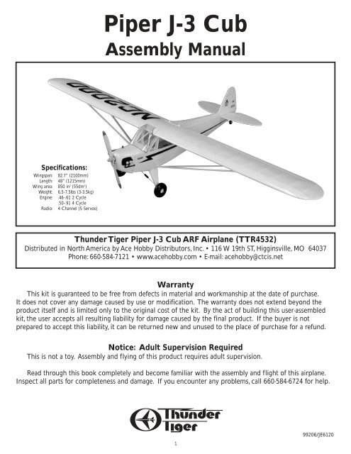
<strong>Piper</strong> J-3 <strong>Cub</strong><br />
<strong>Assembly</strong> <strong>Manual</strong><br />
Specifications:<br />
Wingspan: 82.7” (2100mm)<br />
Length: 48” (1215mm)<br />
Wing area: 850 in 2 (55dm 2 )<br />
Weight: 6.5-7.5lbs (3-3.5kg)<br />
Engine: .46-.61 2 Cycle<br />
.50-.91 4 Cycle<br />
Radio: 4 Channel (5 Servos)<br />
Thunder Tiger <strong>Piper</strong> J-3 <strong>Cub</strong> ARF Airplane (TTR4532)<br />
Distributed in North America by Ace Hobby Distributors, Inc. • 116 W 19th ST, Higginsville, MO 64037<br />
Phone: 660-584-7121 • www.acehobby.com • E-mail: acehobby@ctcis.net<br />
Warranty<br />
This kit is guaranteed to be free from defects in material and workmanship at the date of purchase.<br />
It does not cover any damage caused by use or modification. The warranty does not extend beyond the<br />
product itself and is limited only to the original cost of the kit. By the act of building this user-assembled<br />
kit, the user accepts all resulting liability for damage caused by the final product. If the buyer is not<br />
prepared to accept this liability, it can be returned new and unused to the place of purchase for a refund.<br />
Notice: Adult Supervision Required<br />
This is not a toy. <strong>Assembly</strong> and flying of this product requires adult supervision.<br />
Read through this book completely and become familiar with the assembly and flight of this airplane.<br />
Inspect all parts for completeness and damage. If you encounter any problems, call 660-584-6724 for help.<br />
1<br />
99206/JE6120
@@@?f<br />
@@@?f<br />
@@@?f<br />
@@@?f<br />
@@@?f<br />
@@@?f<br />
@@@?f<br />
@@@?f<br />
@@@?f<br />
@@@?f<br />
@@@?f<br />
@@@?f<br />
@@@?f<br />
@@@?f<br />
@@@?f<br />
@@@?f<br />
@@@?f<br />
@@@?f<br />
@@@?f<br />
@@@?f<br />
@@@?f<br />
@@@?f<br />
@@@?f<br />
@@@?f<br />
@@@?f<br />
@@@?f<br />
@@@?f<br />
@@@?f<br />
@@@?f<br />
@@@?f<br />
@@@?f<br />
@@@?f<br />
@@@?f<br />
@@@?f<br />
@@@?f<br />
@@@?f<br />
@@@?f<br />
@@@?f<br />
@@@?f<br />
@@@?f<br />
@@@?f<br />
@@@?f<br />
@@@?f<br />
@@@?f<br />
@@@?f<br />
@@@?f<br />
@@@?f<br />
@@@?f<br />
@@@?f<br />
@@@?f<br />
@@@?f<br />
@@@?f<br />
@@@?f<br />
@@@?f<br />
@@@?f<br />
@@@?f<br />
@@@?f<br />
@@@?f<br />
@@@?f<br />
@@@?f<br />
@@@?f<br />
@@@?f<br />
@@@?f<br />
@@@?f<br />
@@@?f<br />
@@@?f<br />
@@@?f<br />
@@@?f<br />
@@@?f<br />
@@@?f<br />
@@@?f<br />
@@@?f<br />
@@@?f<br />
@@@?f<br />
@@@?f<br />
@@@?f<br />
@@@?f<br />
@@@?f<br />
@@@?f<br />
@@@?f<br />
@@@?f<br />
@@@?f<br />
@@@?f<br />
@@@?f<br />
@@@?f<br />
@@@?f<br />
@@@?f<br />
@@@?f<br />
@@@?f<br />
@@@?f<br />
@@@?f<br />
@@@?f<br />
@@@?f<br />
@@@?f<br />
@@@?f<br />
@@@?f<br />
@@@?f<br />
@@@?f<br />
@@@?f<br />
@@@?f<br />
@@@?f<br />
@@@?f<br />
@@@?f<br />
@@@?f<br />
@@@?f<br />
@@@?f<br />
@@@?f<br />
@@@?f<br />
@@@?f<br />
@@@?f<br />
@@@?f<br />
@@@?f<br />
@@@?f<br />
@@@?f<br />
@@@?f<br />
@@@?f<br />
@@@?f<br />
@@@?f<br />
@@@?f<br />
@@@?f<br />
@@@?f<br />
@@@?f<br />
@@@?f<br />
@@@?f<br />
@@@?f<br />
@@@?f<br />
@@@?f<br />
@@@?f<br />
@@@?f<br />
@@@?f<br />
@@@?f<br />
@@@?f<br />
@@@?f<br />
@@@?f<br />
@@@?f<br />
@@@?f<br />
@@@?f<br />
@@@?f<br />
@@@?f<br />
@@@?f<br />
@@@?f<br />
@@@?f<br />
@@@?f<br />
@@@?f<br />
@@@?f<br />
@@@?f<br />
@@@?f<br />
@@@?f<br />
@@@?f<br />
@@@?f<br />
@@@?f<br />
@@@?f<br />
@@@?f<br />
@@@?f<br />
@@@?f<br />
@@@?f<br />
@@@?f<br />
@@@?f<br />
@@@?f<br />
@@@?f<br />
@@@?f<br />
@@@?f<br />
@@@?f<br />
@@@?f<br />
@@@?f<br />
?<br />
?<br />
?<br />
?<br />
?<br />
?<br />
?<br />
?<br />
?<br />
?<br />
?<br />
?<br />
?<br />
?<br />
?<br />
?<br />
?<br />
?<br />
?<br />
?<br />
?<br />
?<br />
?<br />
@@@?e?<br />
@@@?e?<br />
@@@?f<br />
@@@?f<br />
@@@?f<br />
@@@?f<br />
@@@?f<br />
@@@?f<br />
@@@?f<br />
@@@?f<br />
@@@?f<br />
@@@?f<br />
@@@?f<br />
@@@?f<br />
@@@?f<br />
@@@?f<br />
@@@?f<br />
@@@?f<br />
@@@?f<br />
@@@?f<br />
@@@?f<br />
@@@?f<br />
@@@?f<br />
@@@?f<br />
@@@?f<br />
@@@?f<br />
@@@?f<br />
@@@?f<br />
@@@?f<br />
@@@?f<br />
@@@?f<br />
@@@?f<br />
@@@?f<br />
@@@?f<br />
@@@?f<br />
@@@?f<br />
@@@?f<br />
@@@?f<br />
@@@?f<br />
@@@?f<br />
@@@?f<br />
@@@?f<br />
@@@?f<br />
@@@?f<br />
@@@?f<br />
@@@?f<br />
@@@?f<br />
?<br />
?<br />
?<br />
?<br />
?<br />
?<br />
?<br />
?<br />
?<br />
?<br />
?<br />
?<br />
?<br />
?<br />
?<br />
?<br />
?<br />
?<br />
?<br />
?<br />
?<br />
?<br />
@@@?e?<br />
@@@?e?<br />
@@@?f<br />
@@@?f<br />
@@@?f<br />
@@@?f<br />
@@@?f<br />
@@@?f<br />
@@@?f<br />
@@@?f<br />
@@@?f<br />
@@@?f<br />
@@@?f<br />
@@@?f<br />
?<br />
?<br />
?<br />
?<br />
?<br />
?<br />
?<br />
?<br />
?<br />
?<br />
?<br />
?<br />
?<br />
?<br />
?<br />
?<br />
?<br />
?<br />
?<br />
?<br />
?<br />
?<br />
@@@?e?<br />
@@@?e?<br />
@@@?f<br />
@@@?f<br />
@@@?f<br />
@@@?f<br />
@@@?f<br />
@@@?f<br />
@@@?f<br />
@@@?f<br />
@@@?f<br />
@@@?f<br />
@@@?f<br />
@@@?f<br />
@@@?f<br />
@@@?f<br />
@@@?f<br />
@@@?f<br />
@@@?f<br />
@@@?f<br />
@@@?f<br />
@@@?f<br />
@@@?f<br />
@@@?f<br />
@@@?f<br />
@@@?f<br />
@@@?f<br />
@@@?f<br />
@@@?f<br />
@@@?f<br />
@@@?f<br />
@@@?f<br />
@@@?f<br />
@@@?f<br />
@@@?f<br />
@@@?f<br />
@@@?f<br />
@@@?f<br />
@@@?f<br />
@@@?f<br />
@@@?f<br />
@@@?f<br />
@@@?f<br />
@@@?f<br />
?<br />
?<br />
?<br />
?<br />
?<br />
?<br />
?<br />
?<br />
?<br />
?<br />
?<br />
?<br />
?<br />
?<br />
?<br />
?<br />
?<br />
?<br />
?<br />
?<br />
?<br />
?<br />
@@@?e?<br />
@@@?e?<br />
@@@?f<br />
@@@?f<br />
@@@?f<br />
@@@?f<br />
@@@?f<br />
@@@?f<br />
@@@?f<br />
@@@?f<br />
@@@?f<br />
@@@?f<br />
@@@?f<br />
@@@?f<br />
@@@?f<br />
@@@?f<br />
@@@?f<br />
@@@?f<br />
@@@?f<br />
@@@?f<br />
@@@?f<br />
@@@?f<br />
@@@?f<br />
@@@?f<br />
@@@?f<br />
@@@?f<br />
@@@?f<br />
@@@?f<br />
@@@?f<br />
@@@?f<br />
@@@?f<br />
@@@?f<br />
@@@?f<br />
@@@?f<br />
@@@?f<br />
@@@?f<br />
@@@?f<br />
@@@?f<br />
@@@?f<br />
@@@?f<br />
@@@?f<br />
@@@?f<br />
@@@?f<br />
@@@?f<br />
@@@?f<br />
@@@?f<br />
@@@?f<br />
?<br />
?<br />
?<br />
?<br />
?<br />
?<br />
?<br />
?<br />
?<br />
?<br />
?<br />
?<br />
?<br />
?<br />
?<br />
?<br />
?<br />
?<br />
?<br />
?<br />
?<br />
?<br />
@@@?e?<br />
@@@?e?<br />
@@@?f<br />
@@@?f<br />
@@@?f<br />
@@@?f<br />
@@@?f<br />
@@@?f<br />
@@@?f<br />
@@@?f<br />
@@@?f<br />
@@@?f<br />
@@@?f<br />
@@@?f<br />
@@@?f<br />
@@@?f<br />
@@@?f<br />
@@@?f<br />
@@@?f<br />
@@@?f<br />
@@@?f<br />
@@@?f<br />
@@@?f<br />
@@@?f<br />
@@@?f<br />
@@@?f<br />
@@@?f<br />
@@@?f<br />
@@@?f<br />
@@@?f<br />
@@@?f<br />
@@@?f<br />
@@@?f<br />
@@@?f<br />
@@@?f<br />
@@@?f<br />
@@@?f<br />
@@@?f<br />
@@@?f<br />
@@@?f<br />
@@@?f<br />
@@@?f<br />
@@@?f<br />
@@@?f<br />
@@@?f<br />
@@@?f<br />
@@@?f<br />
@@@?f<br />
@@@?f<br />
@@@?f<br />
?<br />
?<br />
?<br />
?<br />
?<br />
?<br />
?<br />
?<br />
?<br />
?<br />
?<br />
?<br />
?<br />
?<br />
?<br />
?<br />
?<br />
?<br />
?<br />
?<br />
?<br />
?<br />
@@@?e?<br />
@@@?e?<br />
@@@?f<br />
@@@?f<br />
@@@?f<br />
@@@?f<br />
@@@?f<br />
@@@?f<br />
@@@?f<br />
@@@?f<br />
@@@?f<br />
@@@?f<br />
@@@?f<br />
@@@?f<br />
@@@?f<br />
@@@?f<br />
@@@?f<br />
@@@?f<br />
@@@?f<br />
@@@?f<br />
@@@?f<br />
@@@?f<br />
@@@?f<br />
@@@?f<br />
@@@?f<br />
@@@?f<br />
@@@?f<br />
@@@?f<br />
@@@?f<br />
@@@?f<br />
@@@?f<br />
@@@?f<br />
@@@?f<br />
@@@?f<br />
@@@?f<br />
@@@?f<br />
@@@?f<br />
@@@?f<br />
@@@?f<br />
@@@?f<br />
@@@?f<br />
@@@?f<br />
@@@?f<br />
@@@?f<br />
@@@?f<br />
@@@?f<br />
@@@?f<br />
@@@?f<br />
@@@?f<br />
?<br />
?<br />
?<br />
?<br />
?<br />
?<br />
?<br />
?<br />
?<br />
?<br />
?<br />
?<br />
?<br />
?<br />
?<br />
?<br />
?<br />
?<br />
?<br />
?<br />
?<br />
?<br />
@@@?e?<br />
@@@?e?<br />
@@@?f<br />
@@@?f<br />
@@@?f<br />
@@@?f<br />
@@@?f<br />
@@@?f<br />
@@@?f<br />
@@@?f<br />
@@@?f<br />
@@@?f<br />
@@@?f<br />
@@@?f<br />
@@@?f<br />
@@@?f<br />
@@@?f<br />
@@@?f<br />
@@@?f<br />
@@@?f<br />
@@@?f<br />
@@@?f<br />
@@@?f<br />
@@@?f<br />
@@@?f<br />
@@@?f<br />
@@@?f<br />
@@@?f<br />
@@@?f<br />
@@@?f<br />
@@@?f<br />
@@@?f<br />
@@@?f<br />
@@@?f<br />
@@@?f<br />
@@@?f<br />
@@@?f<br />
@@@?f<br />
@@@?f<br />
@@@?f<br />
@@@?f<br />
@@@?f<br />
@@@?f<br />
?<br />
?<br />
?<br />
?<br />
?<br />
?<br />
?<br />
?<br />
?<br />
?<br />
?<br />
?<br />
?<br />
?<br />
?<br />
?<br />
?<br />
?<br />
?<br />
?<br />
?<br />
?<br />
@@@?e?<br />
@@@?e?<br />
@@@?f<br />
@@@?f<br />
@@@?f<br />
@@@?f<br />
@@@?f<br />
@@@?f<br />
@@@?f<br />
@@@?f<br />
@@@?f<br />
@@@?f<br />
@@@?f<br />
@@@?f<br />
@@@?f<br />
@@@?f<br />
@@@?f<br />
@@@?f<br />
@@@?f<br />
@@@?f<br />
?<br />
?<br />
?<br />
?<br />
?<br />
?<br />
?<br />
?<br />
?<br />
?<br />
?<br />
?<br />
?<br />
?<br />
?<br />
?<br />
?<br />
?<br />
?<br />
?<br />
?<br />
?<br />
@@@?e?<br />
@@@?e?<br />
@@@?f<br />
@@@?f<br />
@@@?f<br />
@@@?f<br />
@@@?f<br />
@@@?f<br />
@@@?f<br />
@@@?f<br />
@@@?f<br />
@@@?f<br />
@@@?f<br />
@@@?f<br />
@@@?f<br />
?<br />
?<br />
?<br />
?<br />
?<br />
?<br />
?<br />
?<br />
?<br />
?<br />
?<br />
?<br />
?<br />
?<br />
?<br />
?<br />
?<br />
?<br />
?<br />
?<br />
?<br />
?<br />
@@@?e?<br />
@@@?e?<br />
@@@?e?<br />
????????????<br />
@@@?f<br />
@@@?f<br />
@@@?f<br />
@@@?f<br />
@@@?f<br />
@@@?f<br />
@@@?f<br />
@@@?f<br />
@@@?f<br />
@@@?f<br />
@@@?f<br />
INTRODUCTION<br />
One of the most recognized names in aviation history is the <strong>Piper</strong> J-3 <strong>Cub</strong>. A child of the Depression,<br />
Mr. <strong>Piper</strong>’s <strong>Cub</strong> began production in the early ‘30s, evolving into the 65 HP J-3 version in 1939. Proliferating<br />
in the years before and during WWII, the <strong>Cub</strong> has introduced more young men to the joys of flight than any<br />
other airplane ever.<br />
Now you can own a part of aviation’s history and enjoy the relaxing and realistic flight characteristics of<br />
the venerable J-3 <strong>Cub</strong>. Thunder Tiger’s ARF J-3 has been meticulously built from the finest material and covered<br />
with UltraCote® in the classic <strong>Cub</strong> Yellow color scheme. Scale details such as wing struts, landing gear<br />
bungees, <strong>Cub</strong> wheels, accurately contoured fuselage, and dummy engine cylinder heads create a headturning<br />
beauty. Only a few hours of enjoyable assembly and you are ready to step back in time and be a<br />
part of history by flying the classic, IMAA legal J-3 <strong>Cub</strong>.<br />
PRE-ASSEMBLY NOTES<br />
Before beginning the assembly read the instructions thoroughly to give an understanding of the<br />
sequence of steps and a general awareness of the recommended assembly procedures.<br />
By following these instructions carefully and referring to the corresponding pictures, the assembly of<br />
your model will be both enjoyable and rewarding. The result will be a well built, easy to assemble A.R.F.<br />
model, which you will be proud to display and also provide you flying excitement not unlike its full-scale<br />
counterpart.<br />
If you are not an experienced R/C pilot, plan to have a fully competent pilot check your completed<br />
model and help you with your first flights. Even though we have tried to provide you with a very thorough<br />
instruction manual, R/C models are rather complicated and an experienced modeler can quickly check over<br />
your model to help make sure your first flights are successful. Your J-3 <strong>Cub</strong> is designed for intermediate to<br />
advanced pilots.<br />
Before you begin, check the entire contents of your kit<br />
against the parts list and photos to make sure that no parts<br />
are missing or damaged. This will also help you to become<br />
familiar with each component of your plane. If you find<br />
that any of the parts are either missing or damaged, please<br />
contact Ace Hobby Distributors, Inc., Customer Service<br />
(660-584-6704) immediately for replacements.<br />
Note: Neither your dealer nor<br />
Ace Hobby Distributors, Inc., can accept<br />
kits for return if construction has begun.<br />
Trial fit each part before gluing it in place. Make sure<br />
you are using the correct part and that it fits well before<br />
assembling. No amount of glue can make up for a poorfitting<br />
part.<br />
Introduction<br />
Other Items Required<br />
Items Needed Check List<br />
@@@?f<br />
@@@?f<br />
@@@?f<br />
Parts Sketches<br />
Wing <strong>Assembly</strong><br />
Fuselage <strong>Assembly</strong><br />
@@@?f<br />
Stabilizer <strong>Assembly</strong><br />
Engine & Fuel Tank Installation<br />
Radio Installation<br />
Cowl Installation<br />
@@@?f<br />
Windshield Installation<br />
Wing Strut Attachment<br />
@@@?f<br />
@@@?f<br />
@@@?f<br />
Balance<br />
TABLE OF CONTENTS<br />
Control Throws<br />
Flying Hints<br />
@@@?f<br />
Pre-Flight Checks<br />
Safety Precautions<br />
Post-Flight Check List<br />
@@@?f<br />
2<br />
2<br />
@@@?f<br />
@@@?f<br />
3<br />
4-5<br />
@@@?f<br />
@@@?f<br />
6-9<br />
10-12<br />
@@@?f<br />
@@@?f<br />
12-14<br />
14-15<br />
@@@?f<br />
@@@?f<br />
16-18<br />
19<br />
@@@?f<br />
@@@?f<br />
20<br />
20-21<br />
@@@?f<br />
@@@?f<br />
21<br />
21<br />
@@@?f<br />
@@@?f<br />
22<br />
22<br />
@@@?f<br />
@@@?f<br />
?<br />
22<br />
?<br />
?<br />
?<br />
?<br />
?<br />
?<br />
?<br />
?<br />
@@@?e? @@@?e? @@@?e? @@@?e? @@@?e? @@@?e? @@@?e? @@@?e? @@@?e?<br />
???????????? ???????????? ???????????? ???????????? ???????????? ???????????? ???????????? ???????????? ????????????<br />
22<br />
2
Adhesives:<br />
Instant setting Cyanoacrylate adhesive (thin CA)<br />
Slow setting Cyanoacrylate adhesive (thick CA)<br />
10 Minute Epoxy (fast)<br />
20-30 Minute Epoxy (slow)<br />
R/C 56 Glue<br />
RECOMMENDED TOOLS & MATERIALS<br />
Tools:<br />
Model knife,T-Pins, 1/2” vinyl tape<br />
Small screwdrivers, Medium screwdrivers<br />
Scissors<br />
Steel straight edge<br />
Long nose pliers and diagonal cutting pliers<br />
Drill and drill bits<br />
Sanding block<br />
Fine felt tip pen and soft lead pencil<br />
Straight building board<br />
Adhesives - You will need two types of adhesives<br />
for the Fun Tiger - Epoxy and Instant (cyanoacrylate)<br />
adhesives. We recommend that you purchase both<br />
5-minute and 30-minute epoxy to cut down on<br />
assembly time, but you can get by with only 30-<br />
minute epoxy if time is not important.You will also<br />
need a small bottle of both “Thick” and “Thin”<br />
instant adhesive.<br />
R/C System:<br />
4 Channel radio with 5 servos<br />
Engine:<br />
2 cycle: .40 to .61 CID<br />
4 cycle: .50 to .91 CID<br />
Propeller (appropriate for engine type and<br />
preferred performance)<br />
Tools - Model assembly can be much easier if the<br />
proper tools are used. Therefore, we have included<br />
in our checklist to the left, a complete listing of all<br />
the tools we used to assemble our prototype models.<br />
As you will notice, many household tools can be<br />
utilized during construction.<br />
Radio - A 4-channel radio with five standard servos<br />
is required.<br />
Engine - The Thunder Tiger PRO-46 and F-54S are<br />
the ideal engines for this airplane. These quiet-running<br />
engines are easy to start, require no special<br />
break-in periods, are very easy to maintain and will<br />
last for years.<br />
3
PARTS DRAWINGS<br />
Fuselage AS6029<br />
Fuel Tank Set #3263<br />
Silicone Tube (1)<br />
Clunk (1)<br />
Fuel Stopper (1)<br />
90" Nipple (1)<br />
Nipple (1)<br />
Fuselage(1)<br />
Cap (1)<br />
300 c.c. Tank (1)<br />
Wing AS6030<br />
M2mm x 8mm<br />
Wing Joiner (3)<br />
Hatch (2)<br />
Wing Bolt Plate (1)<br />
Screw (8)<br />
Trim Tape (1)<br />
Left Wing (1)<br />
Right Wing (1)<br />
Wing Struct AS6031<br />
Wing Struct (2)<br />
Mounting Plate (6)<br />
M3mm x 5mm<br />
Screw (6)<br />
M3mm x 8mm<br />
Tapping Screw (6)<br />
Horizontal Tail AS6032<br />
Vertical Tail AS6033<br />
Vertical Fin (1) Rudder (1)<br />
1/8" Wire<br />
Stabilizer (1) Elevator (2) Elevator Joiner (1)<br />
Shrink tube<br />
AS6034<br />
Aft Pushrods AS6035<br />
Aileron Pushrods #3152<br />
Clevis (2)<br />
Shrink tube (4)<br />
Stab/Rudder Pushrods(2) Clevis (2)<br />
Threaded Rod (2)<br />
Control Horn Set #3151<br />
Main wheel #3101<br />
Control Horn (2)<br />
M2mm x 15mm<br />
M2mm X 6mm<br />
Back Plate (2) Screw (4) Main Wheels (2) Hub Cover(2) Screw (6)<br />
M2mm X 3mm<br />
Screw (6)<br />
4
5<br />
PARTS DRAWINGS
WING ASSEMBLY<br />
❐ Identify the right and left wing panels. Carefully remove the tape<br />
that temporarily secures the ailerons to each wing panel.<br />
❐ Carefully remove all hinges from the ailerons and apply a small drop<br />
of oil to each hinge on the hinge pin. (Photo 1)<br />
Photo 1<br />
❐ With the right wing panel once again upside down on the building<br />
board, determine the aileron servo location (2nd wing bay in from the<br />
inboard edge of the aileron). Using a felt tip pen, draw a cutting line<br />
3/16” inside the bay. Carefully cut away the covering and seal the<br />
edges using a heating iron. (Photos 5, 6 & 7)<br />
Photo 5<br />
❐ Apply 20-30 Minute Epoxy to one half of each hinge and insert into<br />
the right aileron. Set aside to cure and repeat procedure for the left<br />
aileron. (Photo 2)<br />
Photo 6<br />
Photo 2<br />
❐ Apply 20-30 Minute Epoxy to the exposed portion of the hinges on<br />
the right aileron. Carefully fit the aileron into the right wing panel.<br />
Wipe off any excess epoxy using denatured (rubbing) alcohol. Set<br />
aside to cure. Repeat the same procedure for the left wing aileron and<br />
wing panel. (Photo 3)<br />
Photo 7<br />
Photo 3<br />
❐ Obtain two servo extensions that give you the necessary lead<br />
length for your aileron servos (12” or so). Join the aileron servo and<br />
servo extension. Cover the connection with heat shrink tubing provided<br />
and using a heat gun shrink the tubing over the connectors.<br />
(Photo 8).<br />
❐ Place the right wing panel upside down on the building board.<br />
Locate the exit hole for the aileron extension. Using a model knife,<br />
carefully cut and remove the covering material covering the exit hole.<br />
Repeat the procedure for the left wing panel. (Photo 4)<br />
Photo 8<br />
Photo 4<br />
6
WING ASSEMBLY<br />
❐ Insert a piece of piano wire through the root rib of the wing panel<br />
and “fish” the aileron servo lead through the wing. (Photos 9 & 10)<br />
Photo 9<br />
❐ Place the servo hold down plate over the servo and drill through<br />
the plate into the servo mount taking caution not to drill through the<br />
wing. (Photo 13)<br />
Photo 13<br />
Photo 10<br />
❐ Using M2.5X8 wood screws, screw the servo hold down plate in<br />
place (Photo 14)<br />
Photo 14<br />
❐ Use a pair of tweezers to pull the servo lead through the exit hole<br />
in the wing panel (Photo 11).<br />
Photo 11<br />
❐ Locate the correct servo cover and install in the right wing panel.<br />
❐ Drill 4 3/64” holes at the four corners. (Photo 15)<br />
Photo 15<br />
❐ Place the servo in the wing panel in the servo mount. (Photo 12)<br />
Photo 12<br />
7
WING ASSEMBLY<br />
❐ Place the control horn on the aileron and align with the servo<br />
horn slot in the hatch cover. Drill holes using the control horn as a<br />
template. Secure the control horn with two M2x12 screws and the<br />
backer plate. (Photo 16)<br />
Photo 16<br />
❐ Locate the three wing joiners (2 plywood and 1 aluminum). Apply<br />
a coat of 5-10 Minute Epoxy to each side of the aluminum joiner and<br />
mate the 2 plywood joiner to it. Clamp the assembly together and set<br />
aside to cure. (Photos 20 & 21)<br />
Photo 20<br />
❐ Locate the control clevis and thread onto the push rod. Snap the<br />
clevis onto the control with the servo at the neutral position. Mark the<br />
clevis for the “Z” bend. (Photo 17)<br />
Photo 21<br />
Photo 17<br />
❐ Draw a center line on the wing joiner and trial fit into the spar box<br />
on each wing panel. Sand to fit as necessary. (Photo 22)<br />
Photo 22<br />
❐ Remove the clevis, cut off the excess wire and insert the “Z” bend<br />
through the hatch cover then into the servo horn. Snap the clevis<br />
onto the control horn. Secure the hatch cover with 4 M2x8 wood<br />
screws. (Photos 18 & 19)<br />
Photo 18 Photo 19<br />
❐ When the two wing panels match up perfectly, apply 30-45 Minute<br />
Epoxy to the wing joiner on one half only. Liberally apply 30-45<br />
Minute Epoxy to the spar box in the right wing panel. Insert the joiner<br />
into the spar box wiping off any excess epoxy. Set aside to cure.<br />
(Photo 23)<br />
Photo 23<br />
❐ Repeat the above procedures for the left wing panel.<br />
SUGGESTION: Secure any clevis/control horn connection with a<br />
piece of medium fuel tubing about 1/4” long. (Not Shown)<br />
8
WING ASSEMBLY<br />
❐ Apply 30-45 Minute Epoxy to the left wing panel spar box as well<br />
as the entire root rib. Carefully join the two wing panels together.<br />
Wipe off any excess epoxy. Block up each wing tip 5/8” and allow to<br />
cure. It may be necessary to use masking tape to hold the wing panels<br />
in position until cured. Photo 24)<br />
Photo 24<br />
❐ Place the wing on the fuselage. Carefully align the wing ensuring<br />
that it is centered on the fuselage. Using a 19/64” (7.4mm) drill bit,<br />
drill through the wing into the wing hold down plate in the fuselage<br />
using the previously drilled holes as a reference. (Photo 27)<br />
Photo 27<br />
❐ Use the hardwood wing bolt plate as a template. Draw a reference<br />
line on the top of the wing at the trailing edge. Using a hobby knife<br />
carefully cut the covering and remove from the wing. Use caution not<br />
to cut into the wing skin. (Photo 25)<br />
Photo 25<br />
❐ Remove the wing from the fuselage. Install the blind nuts in the<br />
bottom of the wing hold down mounting plate. Install the wing hold<br />
screws in the blind nuts and pull up tightly ensuring that the blind<br />
nuts are secured in place. (Photo 28)<br />
Photo 28<br />
❐ Using 5-10 Minute Epoxy, glue the hardwood wing bolt plate into<br />
place. Locate and mark a reference point 5/8”in from each side and 1-<br />
3/8” up from the trailing edge of the wing. Using a 9/32” (7mm) drill,<br />
drill a hole through the wing at each reference mark.(Photo 26)<br />
Photo 26<br />
❐ Remove the wing bolts and trial mount the wing to the fuselage.<br />
Adjust as necessary to ensure proper alignment. (Photo 29)<br />
Photo 29<br />
❐ Remove the wing and cover the center joint with the trim covering<br />
provided.<br />
9
FUSELAGE ASSEMBLY<br />
❐ Carefully cut away the covering over the landing gear slot on the<br />
bottom of the fuselage. (Photo 30)<br />
Photo 30<br />
❐ Reinstall the landing gear and secure it in place with 4 M3x8 wood<br />
screws. (Photo 33)<br />
Photo 33<br />
❐ Position the preformed landing gear in place. Locate the landing<br />
gear retaining plates (2) and place them over the landing gear. Using<br />
a felt tip pen mark the location for the mounting screws. (Photo 31)<br />
Photo 31<br />
❐ Locate the <strong>Cub</strong> Wheels and secure the hub in place with the<br />
provided screws. (Photo 34)<br />
Photo 34<br />
❐ Remove the landing gear and drill 4 5/64” (2mm) holes. (Photo 32)<br />
Photo 32<br />
❐ Insert a 5mm-wheel collar (w/set screw) onto the landing gear.<br />
Do not tighten at this time (Photo 35)<br />
Photo 35<br />
10
FUSELAGE ASSEMBLY<br />
❐ Install the <strong>Cub</strong> Wheel followed by another 5mm-wheel collar.<br />
Ensure that the wheel collar is even with the edge of the landing gear<br />
axle and secure it in place with the “L” wrench provided. (Photo 36)<br />
Photo 36<br />
❐ Carefully bend the mounting plates to a 45-degree angle then<br />
secure to the fairings with M2.6x6 screws and M2.6 nuts. (Photo 39)<br />
Photo 39<br />
❐ Hold the landing gear fairing in place. Using a felt tip pen mark the<br />
location on the fuselage for the mounting screw. Ensure that the landing<br />
gear fairing is located underneath the bottom/corner of the fuselage.<br />
(Photo 40)<br />
Photo 40<br />
❐ Place the hubcap on the <strong>Cub</strong> Wheel and mount it in place with the<br />
small screws provided. Secure the original wheel collar against the<br />
back of the <strong>Cub</strong> Wheel allowing freedom of motion without being too<br />
loose. (Photo 37)<br />
Photo 37<br />
❐ Drill 5/64” (2mm) holes at the marked locations. (Photo 41)<br />
Photo 41<br />
❐ Locate the pre-covered landing gear fairings. Drill 2 7/64”(2.6mm)<br />
holes as shown. (Photo 38)<br />
Photo 38<br />
11
FUSELAGE ASSEMBLY/STABILIZER ASSEMBLY<br />
❐ Mount the landing gear fairings in place using 4 M3x8 wood<br />
screws. (Photo 42)<br />
❐ Attach the elevator joiner wire to each elevator half with thick CA<br />
or 5 minute epoxy. (Photo 45)<br />
Photo 42 Photo 45<br />
❐ Remove the hinges from the horizontal stabilizer and apply a drop<br />
of oil to each hinge. Apply 10-20 minute epoxy to one side of each<br />
hinge and install in each elevator half. Set aside to cure. (Photo 46)<br />
❐ Secure the lower portion of the landing gear fairings to the landing<br />
gear using the small nylon tie wraps provided. (Photo 43)<br />
Photo 46<br />
Photo 43<br />
❐ Apply 10-20 minute epoxy to the hinges on the elevators and install<br />
them on the horizontal stabilizer. Allow curing then cut a notch in the<br />
covering at the center leading edge for the vertical stabilizer.<br />
(Photo 47)<br />
STABILIZER ASSEMBLY<br />
Photo 47<br />
❐ Locate both elevator halves. Carefully cut away the covering on the<br />
elevators where the wire elevator joiner is to be installed (Photo 44)<br />
Photo 44<br />
❐ At the rear of the fuselage locate the positions for the horizontal<br />
and vertical stabilizers. Using a hobby knife carefully cut away the<br />
covering over these areas. (Photo 48)<br />
Photo 48<br />
12
STABILIZER ASSEMBLY<br />
❐ Temporarily install the horizontal and vertical stabilizers (in that<br />
order). Using a felt tip pen mark the fuselage location on both the<br />
horizontal and vertical stabilizers. (Photo 49)<br />
❐ Cut a slot on the leading edge of the rudder. Trial fit the tail wheel<br />
gear wire to the rudder. Cut a notch in the leading edge of the rudder<br />
to allow clearance for the elevator joiner wire (Photo 52)<br />
Photo 49 Photo 52<br />
❐ Remove the horizontal and vertical stabilizers from the fuselage.<br />
Using a hobby knife cut the covering along the marked lines being<br />
careful not to cut in the wood which could result in structural failure.<br />
(Photo 50)<br />
Photo 50<br />
❐ Locate the hinges for the rudder and place a drop of oil on each<br />
hinge joint. Using 10-20 minute epoxy apply epoxy to one side of the<br />
hinges and install them into the rudder. Install the tail wheel gear wire<br />
into the rudder at this time also using epoxy. Set aside until cured.<br />
(Photo 53)<br />
Photo 53<br />
❐ Mount the wing to the fuselage. Using 30-45 minute epoxy, install<br />
the horizontal and vertical stabilizers in position. Ensure that the horizontal<br />
stabilizer is parallel with the wing and that the vertical stabilizer<br />
is 90-degrees to the horizontal stabilizer. Set aside until cured.<br />
❐ Locate the tail wheel wire hole on the rudder. Cut a slot in the fuselage<br />
for the tail wheel gear wire hinge. (Photo 51)<br />
❐ Apply 10-20 minute epoxy to the hinges and install the rudder and<br />
tail wheel gear wire into the vertical stabilizer and fuselage respectively.<br />
Press together as tightly as possible to ensure minimal gap<br />
between the rudder and vertical stabilizer. Install the tail wheel<br />
mounting plate as shown with 2 M3x8 wood screws. (Photo 54).<br />
Photo 54<br />
Photo 51<br />
13
STABILIZER ASSEMBLY<br />
❐ Install the tail wheel and secure in place with the provided wheel<br />
collar. (Photo 55)<br />
Photo 55<br />
ENGINE & FUEL TANK INST.<br />
❐ Locate the rubber spacer and adjustable engine mount. Hold in<br />
place on the fuselage firewall and verify fit. Mount the rubber spacer<br />
and engine mount to the firewall but do not secure it in place at this<br />
time. (Photo 58)<br />
Photo 58<br />
❐ Locate the elevator control horn on the right elevator with the<br />
clevis holes in line with the hinge line. Drill 2 5/64”(2mm) holes using<br />
the control horn base as a template. Secure the elevator control horn<br />
to the elevator using 2 M2x15 screws and the control horn backplate.<br />
(Photo 56)<br />
Photo 56<br />
❐ Assemble the fuel tank as shown taking care to insure that the fuel<br />
tank clunk is not restricted in motion. (Photo 59)<br />
Photo 59<br />
❐ Using the same procedure as for the elevator control horn, install<br />
the rudder control on the left side of the rudder. (Photo 57)<br />
Photo 57<br />
❐ Cut three 6-8”pieces of standard fuel tubing to length. Install them<br />
on the fuel tank nipples and install the fuel tank in the fuel tank compartment.<br />
Note that it is easier to feed the lines through the firewall<br />
if they are tied together with a piece of line and pulled through.<br />
(Photo 60)<br />
❐ Secure the tank in place with small foam blocks or foam rubber.<br />
(Photo 61)<br />
Photo 60<br />
Photo 61<br />
14
ENGINE & FUEL TANK INSTALLATION<br />
❐ Install the throttle push-rod tube through the firewall and into the<br />
radio compartment. (Photo 62)<br />
Photo 62<br />
❐ Remove the engine and drill a 5/64” (2mm) hole at each of the<br />
marks. (Photo 65)<br />
Photo 65<br />
❐ Leave approximately 1/4” of the push-rod tube extending into the<br />
engine compartment. Epoxy in place. (Photo 63)<br />
Photo 63<br />
❐ Secure the engine to the motor mount using the 4 M3x20 self-tapping<br />
screws provided. Secure the adjustable engine mount at this time<br />
and make sure there is 2-degree right thrust angle. (Photo 66)<br />
Photo 66<br />
❐ Place the engine on the adjustable motor mount and locate the<br />
front drive hub 4-13/16” from the firewall. Mark the mounting hole<br />
locations on the motor mount. (Photo 64)<br />
Photo 64<br />
❐ If installing the recommended Thunder Tiger F-54S engine, extend<br />
the choke valve wire insuring that it is long enough to clear the cowling.<br />
(Photo 67)<br />
Photo 67<br />
15
RADIO INSTALLATION<br />
❐ Install the switch harness as shown. Wrap the battery pack in foam<br />
and install underneath the fuel tank (Photo 68). You may have to<br />
adjust the battery location to obtain the proper CG.<br />
Photo 68<br />
❐ Install the three servos in the radio compartment (throttle, rudder,<br />
and elevator). From the tail facing forward from right to left, the servos<br />
are throttle, rudder and elevator. Plug the servos into the receiver<br />
and set neutral. (Photo 72)<br />
Photo 72<br />
Drill a 1/16” hole<br />
in switch lever.<br />
See Step 85.<br />
❐ Locate the antenna guide tube exit at the rear of the fuselage on<br />
the bottom and remove the covering around the exit hole using a<br />
hobby knife (Photo 69).<br />
Photo 69<br />
❐ Install the EZ connector on the throttle servo horn. Place the servo<br />
horn on the servo (Photo 73).<br />
Photo 73<br />
❐ Insert the receiver antenna through the guide tube located under<br />
the servo tray. Leave approximately 2”(5cm) of the antenna extending<br />
outside the exit (Photos 70 & 71).<br />
Photo 70<br />
❐ Remove the throttle lever from the engine. Make a “Z” bend at one<br />
end of the push rod and install it on the throttle lever (Photo 74).<br />
Photo 74<br />
Photo 71<br />
16
RADIO INSTALLATION<br />
❐ Install the other end of the throttle push rod in the EZ connector.<br />
Trim off any excess wire (Photo 75).<br />
❐ Mark the other end of the push rod where the “Z” bend is to be<br />
located (Photo 78).<br />
Photo 75 Photo 78<br />
❐ Using a hobby knife carefully cut away the covering over the elevator<br />
and rudder push-rod exits at the rear of the fuselage (Photo 76).<br />
❐ Using “Z” Bend Pliers bend the push rod at the location marked<br />
(Photo 79).<br />
Photo 79<br />
Photo 76<br />
❐ Insert the “Z” bend into the servo horn. Install the servo horn on<br />
the servo (Photo 80).<br />
Photo 80<br />
❐ Install one push rod with the threaded end first through the fuselage<br />
and exiting at the elevator exit slot. Locate a clevis and thread it<br />
onto the threaded end at least 20 turns. Snap the clevis onto the control<br />
horn at the 3rd hole from the bottom (Photo 77).<br />
Photo 77<br />
17
RADIO INSTALLATION<br />
❐ Install the rudder push rod using the same steps as for the elevator.<br />
(Photos 81, 82, and 83)<br />
Photo 81<br />
❐ Drill a small hole through the fuselage in line with the switch.<br />
Insert the extension wire through the fuselage and place in the switch.<br />
Using needle nose pliers bend the wire to prevent it from coming<br />
loose. (Photos 85 & 86)<br />
Photo 85<br />
Photo 82<br />
Photo 86<br />
Photo 83<br />
❐ Measure the cowl for the engine to be used and trim the cowling<br />
to fit your particular engine. Cut all the inlets along the molded lines.<br />
(Photo 87)<br />
Photo 87<br />
Using a piece of the excess wire bend an extension for the on-off<br />
switch. (Photo 84)<br />
Photo 84<br />
18
COWL INSTALLATION<br />
❐ You may need to make a cut behind the engine cylinder head to<br />
allow the cowling to go into place with minimal effort. (Photo 88)<br />
Photo 88-1<br />
❐ Position the cowl and drill 3 1/16” (1.5mm) holes on both sides<br />
(Photo 91).<br />
Photo 91<br />
Photo 88-2<br />
❐ Secure the cowl with 6 M2.5x8 wood screws. Route fuel lines from<br />
the cowl. One is the fuel filler line and the other goes to the muffler<br />
pressure fitting. The final line is from the engine breather fitting<br />
(4-cycle) and vents via a piece of aluminum tubing held in place on the<br />
muffler with small tie wraps (Photo 92).<br />
Photo 92<br />
❐ With the cowl in position cut a hole for the needle valve and route<br />
the fuel line out of the cowling (Photo 89).<br />
Photo 89<br />
❐ Install the dummy cylinders to the right side of the cowling using<br />
R/C 56 glue. Paint the valve covers silver (Photo 93).<br />
Photo 93<br />
❐ Install the header pipe and muffler (Photo 90).<br />
Photo 90<br />
19
WINDSHIELD INSTALLATION<br />
❐ Cut the windshield along the molded cutting line using a pair of<br />
scissors (Photo 94).<br />
Photo 94<br />
WING STRUT ATTACHMENT<br />
❐ Cut a notch in the wing strut at each end. Drill a 5/64” (2mm) hole<br />
at the wing strut notch (Photo 97).<br />
Photo 97<br />
❐ Secure the mounting plate as shown with a M3x5 wood screw<br />
(Photo 98).<br />
❐ Using black and yellow paint, paint the windshield as shown<br />
(Photo 95).<br />
Photo 98<br />
Photo 95<br />
❐ Refer to Photo 99. The top strut is for the right wing and the lower<br />
strut is for the left wing.<br />
Photo 99<br />
❐ Attach the windshield to the fuselage. Hold the windshield in place<br />
with masking tape. Apply R/C 56 glue along the area where the windshield<br />
meets the fuselage. Allow to cure over night (Photo 96).<br />
Photo 96<br />
20
WING STRUT ATTACHMENT<br />
❐ Bend the mount plates that attach to the wing at a 25-degree angle<br />
so that they are flush with the surface of the wing (Photo 100).<br />
Photo 100<br />
❐ Place the strut on the wing locating the hardwood mounting<br />
blocks. Drill a 5/64” (2mm) hole at each mounting plate (Photo 101).<br />
Photo 101<br />
BALANCE<br />
Center of Gravity location should be between 4 and 4-1/2” back from<br />
the leading edge of the wing. Flying will determine the final balance<br />
point for your particular model.<br />
CONTROL THROWS<br />
Make sure that all control surfaces move in the proper direction.<br />
Set the control surface throws as indicated for the initial flights.<br />
These may be altered later for personal preference.<br />
Elevator: Hi Rate: 1-1/4” up, 1-1/4” down<br />
Low Rate: 3/4” up, 3/4” down<br />
Rudder: Hi Rate: Full deflection left and right not<br />
to interfere with elevators<br />
Low Rate: 1” left, 1” right<br />
Aileron: Hi Rate: 1” up, 3/4” down<br />
Low Rate: 3/4” up, 1/2” down<br />
❐ Secure the wing strut with 2 M3x8 wood screws (Photo 102).<br />
Prior to the first flight ensure that all batteries are properly charged,<br />
that controls all move in the proper direction, and that a thorough<br />
range check is made with and without the engine running.<br />
Photo 102<br />
❐ Place the wing strut on the fuselage directly behind the landing<br />
gear fairing. Mark the position and drill a 5/64” (2mm) hole. Secure<br />
the strut using a M3x8 wood screw (Photo 103).<br />
Photo 103<br />
❐ Repeat the above sequence of steps for the other wing strut.<br />
Apply decals as desired to finish your model.<br />
21
FLIGHT<br />
The J-3 <strong>Cub</strong> is NOT a trainer. We assume you have mastered the<br />
basics of R/C flight. If not, we suggest you learn to fly with a trainer<br />
before attempting flight with the <strong>Cub</strong>. Thunder Tiger has a large selection<br />
of Trainers to choose from. Check with your hobby dealer for his<br />
recommendation.<br />
Since your J-3 <strong>Cub</strong> is a faithful duplicate of its full scale counterpart,<br />
we highly recommend that you fly it just like the real thing. You<br />
will find yourself enjoying the airplane considerable more than if you<br />
simply bore holes in the sky. Energy management and minimum airframe<br />
stress should be utmost in your mind as you pilot the <strong>Cub</strong>. Put<br />
yourself in the cockpit and imagine yourself with your hands on the<br />
stick and your feet on the rudder pedals.<br />
TAKEOFF<br />
You will find that your <strong>Cub</strong> is easy to taxi and the ground handling<br />
is predictable. If it doesn’t track true, you may have to adjust the tail<br />
wheel by bending it a bit using two pairs of pliers.<br />
Since the <strong>Cub</strong> is a high wing airplane, it is sensitive to crosswind<br />
ground loops. Be prepared with opposite aileron to counter-act crosswind<br />
taxiing.<br />
For takeoff, point the plane directly into the wind and gradually<br />
advance throttle while neutalizing the elevator, letting the tail come<br />
up. Increase speed as much as possible before lifting off. Don’t<br />
“horse” the plane off the ground. Remember, fly it like a real one! A<br />
gental climbout looks much more realistic than a 45 degree “aircraft<br />
carrier” takeoff.<br />
FLYING<br />
Remember, fly your <strong>Cub</strong> like the real thing. Coordinate turns<br />
using rudder. Keep the maneuvers gentle, big, and graceful. Do your<br />
turnarounds with a gentle stall-turn. Remember, keep energy management<br />
and minimal airframe stress in mind at all time.<br />
NEVER, NEVER do full throttle snap-rolls. Keep your <strong>Cub</strong> in one<br />
piece.<br />
LANDING<br />
Since the <strong>Cub</strong> has a high lift and lightly loaded wing, it’s a floater.<br />
There are times you will wish you had an anchor to throw out to get<br />
this plane down. Use the largest diameter, lowest pitch prop you can<br />
to get as much prop disc drag as you can.<br />
In wind, the safest way is to keep some power on and plant the<br />
main gear wheels in a two point landing; use the ground drag to slow<br />
the plane down and don’t let the tail drop until you are below stall<br />
speed. Don’t attempt a three pointer unless the wind is calm. Always<br />
be ready to advance the throttle and neutralize the elevator for a goaround.<br />
To perfect your landings, practice is the best teacher. As a matter<br />
of fact, shooting touch and go’s for a whole flight will give you as<br />
much fun as any other type flying with your <strong>Cub</strong>, plus you can finetune<br />
your landing skills.<br />
PRE-FLIGHT CHECK LIST<br />
❐ 1. Check all control surfaces for possible looseness or deterioration.<br />
❐ 2. Check all screws, clevises, nuts and all other connectors to<br />
make sure they are securely fastened.<br />
❐ 3. Check which radio frequencies are being used. Do not turn<br />
on your radio until absolutely sure you are the only one operating<br />
on that frequency.<br />
❐ 4. Check for proper operation of all control surfaces.<br />
❐ 5. Check the level of charge in both the transmitter and receiver<br />
batteries before flying.<br />
❐ 6. Range check the radio both with and without the engine running!<br />
Follow the radio manufacturers instructions for this.<br />
POST-FLIGHT CHECK LIST<br />
❐ 1. Be sure that both the transmitter and receiver switches are<br />
turned off.<br />
❐ 2. Drain all excess fuel from the tank. Fuel left in the tank for<br />
extended periods can “gunk up”the tank,fittings and carburetor.<br />
❐ 3. Clean the plane with paper towels and a light-duty spray<br />
cleanser. Keeping your plane clean will make it last longer<br />
and keep it looking nice.<br />
❐ 4. Put a few drops of after-run or light oil in the carburetor and<br />
turn the prop over a few times (without the glow plug ignited)<br />
to distribute the oil throughout the engine.<br />
❐ 5. Inspect the prop and replace it if any chips or cracks are found.<br />
❐ 6. Inspect the entire plane for covering tears, new dings and<br />
dents, loose screws and connectors and any other wear and<br />
tear.<br />
SAFETY PRECAUTIONS<br />
1. Wear safety glasses when starting and running all model engines.<br />
2. Model engine fuel is very flammable and the flame is very<br />
dangerous because it is almost invisible! Do not smoke or allow<br />
sparks, high heat or other flames near the fuel.<br />
3. Do not run model engines inside a garage or other closed room as<br />
they give off large amounts of deadly carbon monoxide gas.<br />
4. Do not run model engines around gravel, sand or other loose<br />
debris. These materials will be ingested through the carburetor<br />
and can also be kicked up by the prop.<br />
5. Always stay behind the propeller when the engine is running.<br />
Make all engine adjustments from behind the engine.<br />
6. Do not allow loose clothing or other loose objects close to the prop.<br />
7. To stop an engine, cut off the fuel or air supply to the engine.<br />
Do not throw rags or other objects into the prop to stop the<br />
engine.<br />
8. Do not touch the engine or muffler during or right after it has<br />
been running–it gets very hot!<br />
22
CHOOSE THESE OTHER FINE PRODUCTS:<br />
TTR2702 Thunder Tiger Power Monitor<br />
The perfect device to distribute the power of a 12V field box battery:<br />
metered hi efficiency glow driver, fuel pump, and starter.<br />
TTR3302 Thunder Tiger Tiger Tote<br />
Keep all your stuff organized with a Tiger Tote, with a pre-cut power<br />
panel slot and available with or without Remote Starting System.<br />
TTR1658 Thunder Tiger Fuel Pump<br />
Our most popular fuel pump; fuel and defuel from a 12V source;<br />
fuel filter and fuel line included.<br />
TTR1102 Thunder Tiger 4-Way Wrench<br />
Thunder Tiger’s lightweight 4-way wrench fits all glow plugs and prop<br />
nuts, plus has room to store extras.<br />
ACE24020-24030 Ace PowerMaster Starters<br />
Keep all those fingers on your hands with budget-priced Ace R/C<br />
starters, available in two sizes, starting engines from 1/2A to 1.20.<br />
THE PERFECT ENGINE FOR YOUR<br />
J-3 <strong>Cub</strong>!<br />
Ace Electronics<br />
Choose from any of Ace’s battery maintanence electronics<br />
including our world-famous Digipace 3 to the revolutionary<br />
Smart Charge. Time proven usefulness for any R/Cer.<br />
TTR9800 Thunder Tiger F-54S<br />
The F-54S is the perfect engine for your <strong>Cub</strong>,<br />
with plenty of power and a great, realistic sound.<br />
23
Fun Tigers<br />
F-54<br />
Recommended<br />
Engines:<br />
PRO-46<br />
Fun Tiger G-200<br />
Designed by Fred Reese<br />
Fun Tigers<br />
Now you can experience the<br />
breathtaking, adrenaline-pumping<br />
thrills of this HOT category of R/C<br />
planes without having to invest any<br />
building time. Do some simple assembly,<br />
strap on a high-performance .40<br />
engine, such as our PRO-46, install your<br />
radio system, and you are ready to join<br />
in the fun.<br />
These outrageously maneuverable<br />
3-D Fun Fly planes will do just about<br />
anything imaginable, especially<br />
because of Thunder Tiger’s super lightweight<br />
construction. Be a “hot dog”.<br />
Go vertical from dead stop on the runway<br />
in about a fuselage-length of rollout;<br />
do knife-edge loops, rolling circles,<br />
hovering flight, snaps, spins, and anything<br />
your blood pressure will allow.<br />
Choose either the Fun Tiger Extra<br />
or the Fun Tiger Giles-200, replicas of<br />
two of the latest full-scale aerobatic airplanes.<br />
If you want to dress one up in<br />
your favorite color scheme, choose our<br />
Almost-Ready-To-Cover version.<br />
TTR4517 Fun Tiger G-200<br />
TTR4518 Fun Tiger Extra<br />
TTR4522 Fun Tiger ARC<br />
Fun Tiger ARC<br />
Fun Tigers<br />
Wing Span: 47” (1194mm)<br />
Wing Area: 696 in2 (44.9dm2)<br />
Length: 43” (1092mm)<br />
Weight: 4 lbs. (1.8kg)<br />
Engine: .40-.50 2-stroke<br />
.40-.65 4-stroke<br />
Radio: 4 Channel<br />
Fun Tiger Extra<br />
Copyright 1999 by Thunder Tiger Corporation, all rights reserved.<br />
24