Experiment 10 - Multistage Amplifiers
Experiment 10 - Multistage Amplifiers
Experiment 10 - Multistage Amplifiers

You also want an ePaper? Increase the reach of your titles
YUMPU automatically turns print PDFs into web optimized ePapers that Google loves.
Procedure<br />
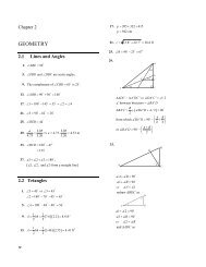
FIGURE 1.<br />
Cascode Amplifier with Current Source Supply<br />
V CC<br />
I SUP<br />
<strong>10</strong>µF<br />
v OUT<br />
M3501<br />
250kΩ<br />
Q 2<br />
V BIAS<br />
1 MΩ<br />
v IN<br />
Q 1<br />
M3501<br />
3.0 Procedure<br />
3.1 The Cascode<br />
The Cascode circuit is nothing more than a Common Emitter - Common Base (or Common<br />
Source - Common Gate) cascade. Figure 1 above shows a simplified cascode with<br />
a current source load.<br />
The 2 port model for the cascode is shown below<br />
FIGURE 2.<br />
2-Port Representation of Cascode<br />
R in G m R out R in -i in2 R out<br />
R L<br />
Common Emitter Stage<br />
Common Base Stage<br />
2 of 5 <strong>Experiment</strong> <strong>10</strong> - <strong>Multistage</strong> <strong>Amplifiers</strong>