
You also want an ePaper? Increase the reach of your titles
YUMPU automatically turns print PDFs into web optimized ePapers that Google loves.
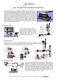
Test data and installation instructions 150 KgM<br />
direct autopilot drive type I.<br />
Customer: ……………<br />
Test data:<br />
Test Engineer: …………..<br />
Date: …………………<br />
Serial number: …………..<br />
Output torque 150 KgM:<br />
<strong>Motor</strong> Voltage: 12 Volts<br />
Clutch voltage: 12 Volts<br />
Insulation test:<br />
Electrical Connections:<br />
autopilot control head<br />
rudder feedback unit<br />
drive unit<br />
autopilot junction box<br />
clutch<br />
output<br />
0,75 mm2<br />
drive<br />
output<br />
2 mm2<br />
fluxgate compass<br />
to battery<br />
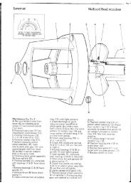
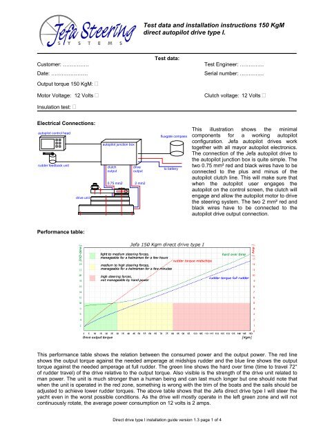
This illustration shows the minimal<br />
components for a working autopilot<br />
configuration. Jefa autopilot drives work<br />
together with all mayor autopilot electronics.<br />
The connection of the Jefa autopilot drive to<br />
the autopilot junction box is quite simple. The<br />
two 0.75 mm² red and black wires have to be<br />
connected to the plus and minus of the<br />
autopilot clutch line. This will make sure that<br />
when the autopilot user engages the<br />
autopilot on the control screen, the clutch will<br />
engage and allow the autopilot motor to drive<br />
the steering system. The two 2 mm² red and<br />
black wires have to be connected to the<br />
autopilot drive output connection.<br />
Performance table:<br />
This performance table shows the relation between the consumed power and the output power. The red line<br />
shows the output torque against the needed amperage at midships rudder and the blue line shows the output<br />
torque against the needed amperage at full rudder. The green line shows the hard over time (time to travel 72°<br />
of rudder travel) of the drive relative to the output torque. Also visible is the strength of the drive unit related to<br />
man power. The unit is much stronger than a human being and can last much longer but one should note that<br />
when the unit is operated in the red zone, something is wrong with the trim of the boats and the sails should be<br />
adjusted to achieve lower rudder torques. The above table shows that the Jefa direct drive type I will steer the<br />
yacht even in the worst possible conditions. As the drive will mostly operate in the left green zone and will not<br />
continuously rotate, the average power consumption on 12 volts is 2 amps.<br />
Direct drive type I installation guide version 1.3 page 1 of 4
Compatibility in 12 Volts:<br />
Following table shows the maximum rudder torques at midships and full rudder that can be generated by the<br />
Jefa 150 Kgm direct drive type 1 in combination with various autopilot junction boxes. The hard over time (HOtime)<br />
states the time it takes the drive to travel the full 72 degrees of rudder travel when the speed control of the<br />
pilot is set to maximum speed.<br />
Autopilot junction box 12 Volt<br />
Max. output (Amp.) <strong>Rudder</strong> torque midships (KgM) <strong>Rudder</strong> torque full rudder (KgM)<br />
version.<br />
Simrad AC10 (J3000X) 10 60 115<br />
Simrad AC20 (J300X) 20 80 150<br />
Simrad AC40 (J300X-40)<br />
overpowered, do not use<br />
B&G H1000 *² 25 80 150<br />
B&G H2000 ACP-1 25 80 150<br />
B&G H2000 ACP-2<br />
overpowered, do not use<br />
Raymarine S1 15 80 150<br />
Raymarine S2 (T150) 20 80 150<br />
Raymarine S3 (T400)<br />
overpowered, do not use<br />
*² Please use part number h1000-CUW specially made for Jefa drives, equipped with dynamic braking. Don't use the standard h1000.<br />
output<br />
center<br />
Mechanical installation:<br />
offset<br />
tiller<br />
center<br />
The direct drive uses “wide angle geometry”. The<br />
result of this is 128° travel of the output lever and<br />
72° travel of the tiller lever. To achieve an equal<br />
travel of the drive in port and starboard, the<br />
centre point of the output lever needs an offset to<br />
the rudderstock centre. The offset depends on<br />
the used lever centres. Following table shows the<br />
correct offset distances:<br />
Operating centres in mm valid for 72° (2x36°) rudder travel.<br />
Output centre Offset distance Tiller centre<br />
130 106 200<br />
165 127 250<br />
65°(2x)<br />
min.300 - max 2000 mm<br />
36°(2x)<br />
A good installation check is to make sure all endposition<br />
points are in one line (see green line in<br />
illustration).<br />
Direct drive type I in combination with rack and pinion system:<br />
ß<br />
In principle the installation in combination with a rack and<br />
pinion system is the same as the standard installation<br />
except for the fact that the complete setup is rotated with<br />
the steering offset angle β.<br />
First install the rack and pinion system with the correct<br />
geometry, put the steering midships and find the line<br />
perpendicular to the tiller lever centre line. Put the drive<br />
on a parallel line with an offset distance as in below table.<br />
Rotate the drive lever to the same offset angle than the<br />
steering system offset angle β and mount the draglink.<br />
offset<br />
ß<br />
Operating centres in mm valid for 72° (2x36°) rudder travel.<br />
Output centre Offset distance Tiller centre<br />
130 106 200<br />
165 127 250<br />
ß<br />
Direct drive type I installation guide version 1.3 page 2 of 4
Drive unit in front of pedestal:<br />
When sufficient space around the rudder shaft isn’t<br />
available, the direct drive can be setup to drive the<br />
rudder via the pedestal.<br />
An extra extended output lever with 165 mm centres<br />
can be fitted to the pedestal down-shaft to be driven by<br />
the direct drive.<br />
8°<br />
top view<br />
36°<br />
8°<br />
The lever geometry between the drive and pedestal is<br />
a parallelogram of 165 mm. The pedestal offset angle<br />
has to be respected, so the hole parallelogram is<br />
rotated around the pedestal centre with the offset<br />
angle.<br />
130<br />
165<br />
165<br />
64°<br />
64°<br />
Reducing noise and vibrations:<br />
DIN912 M8x50<br />
Washer Ø8,5 x Ø16<br />
Rubber washer<br />
Drive unit<br />
Rubber washer<br />
Washer Ø8,5 x Ø25<br />
Mounting plate<br />
Nut DIN985 M8<br />
The vibrations from the autopilot drive motor and gears are often amplified multiple times by the deck or hull.<br />
This noise can be dramatically decreased by using the special bolts, rubber washers and bushes one can find in<br />
the bag supplied with the drive unit. When mounted like in the above illustration, the vibrations will be limited to<br />
the absolute minimum and a smooth and silent installation is guaranteed.<br />
Direct drive type I installation guide version 1.3 page 3 of 4
Test the system:<br />
Before you can test the system, make sure following things are correct:<br />
• Solid rudder stops should be fitted limiting the rudder travel to an equal travel of 36 degrees from<br />
midships to port and starboard.<br />
• Make sure all bolted parts (tiller pins, rosejoints, draglinks, tillerarm,etc) are firmly tightened and will not<br />
come loose even when exposed to heavy vibrations. Use loctite when necessary.<br />
• Move the complete system from port to starboard making sure the rosejoints don’t hit the output lever<br />
and tiller lever.<br />
• Make sure the drive output lever rotates equally around 65 degrees to both sides and there is no risk for<br />
the output lever to go “over dead centre” so it can’t return to the initial position any more, blocking the<br />
system.<br />
Connect the electronics. Make absolutely sure the autopilot is set to “reversible drive” or equivalent. Don’t use<br />
settings like “solenoid” or “hydraulic drive” as these settings will disable the speed control of the autopilot leaving<br />
the drive running at 100% speed or 0%, but nothing in between. Make sure the clutch voltage is set to 12 volts.<br />
Some brands like B&G have default clutch voltage of 9 volts. This should be adjusted to 12 volts to guarantee a<br />
proper working of the clutch.<br />
When the drive doesn’t react to the electronics, test the drive by bypassing the electronics: Connect a plus and<br />
minus wire to the battery or fuse box and first connect the clutch, one should hear a click when connecting and<br />
disconnecting. With the clutch under power, connect power for a short time to the motor cables. The system<br />
should get in motion now. Don’t connect the cables too long as the drive will try to continue, even when the<br />
rudder stops are reached, with potential damage to the structure. If motion is detected, one can rule out the<br />
drive causing the malfunction.<br />
Maintenance:<br />
The direct drive is “greased for life”, so should no be opened. No maintenance is required except for periodic<br />
checks of all bolted connections. As the rudder system, the steering system and the autopilot drive is exposed<br />
to heavy vibrations (mainly by cruising on motor), all bolted connections should be yearly checked. The only<br />
parts that could wear in time are the balls of the draglink. These balls are easy exchangeable and available for<br />
around 10 € each from any Jefa distributor.<br />
Declaration of conformity:<br />
I, Stig Jensen of Jefa Marine Steering ApS, Nimbusvej 2, 2670 Greve, Denmark, confirm that the Jefa direct<br />
drive type I, when fitted in accordance with these installation instructions, will meet the requirements of the<br />
Electro Magnetic Compatibility Directive Standard contained within Standard No. 60945/A1.<br />
Signed:……………………………………………………………. Date: 26-2-2004<br />
Stig Jensen<br />
For more information please visit our website www.jefa.com<br />
Direct drive type I installation guide version 1.3 page 4 of 4