
Create successful ePaper yourself
Turn your PDF publications into a flip-book with our unique Google optimized e-Paper software.
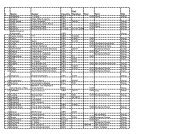
Compatibility in 12 Volts:<br />
Following table shows the maximum rudder torques at midships and full rudder that can be generated by the<br />
Jefa 150 Kgm direct drive type 1 in combination with various autopilot junction boxes. The hard over time (HOtime)<br />
states the time it takes the drive to travel the full 72 degrees of rudder travel when the speed control of the<br />
pilot is set to maximum speed.<br />
Autopilot junction box 12 Volt<br />
Max. output (Amp.) <strong>Rudder</strong> torque midships (KgM) <strong>Rudder</strong> torque full rudder (KgM)<br />
version.<br />
Simrad AC10 (J3000X) 10 60 115<br />
Simrad AC20 (J300X) 20 80 150<br />
Simrad AC40 (J300X-40)<br />
overpowered, do not use<br />
B&G H1000 *² 25 80 150<br />
B&G H2000 ACP-1 25 80 150<br />
B&G H2000 ACP-2<br />
overpowered, do not use<br />
Raymarine S1 15 80 150<br />
Raymarine S2 (T150) 20 80 150<br />
Raymarine S3 (T400)<br />
overpowered, do not use<br />
*² Please use part number h1000-CUW specially made for Jefa drives, equipped with dynamic braking. Don't use the standard h1000.<br />
output<br />
center<br />
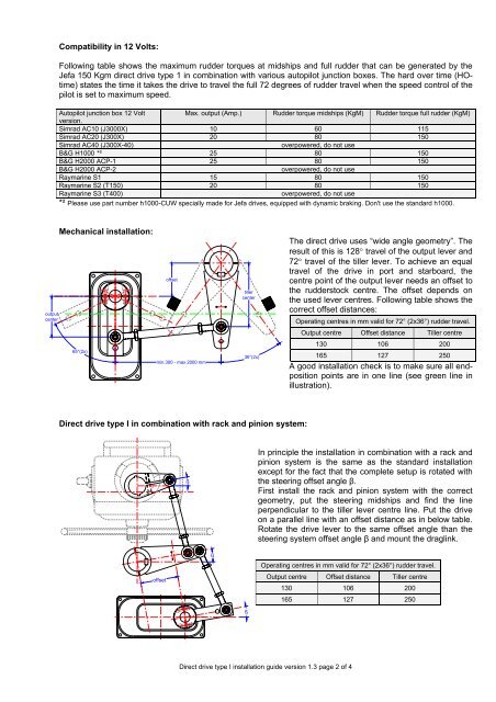
Mechanical installation:<br />
offset<br />
tiller<br />
center<br />
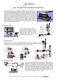
The direct drive uses “wide angle geometry”. The<br />
result of this is 128° travel of the output lever and<br />
72° travel of the tiller lever. To achieve an equal<br />
travel of the drive in port and starboard, the<br />
centre point of the output lever needs an offset to<br />
the rudderstock centre. The offset depends on<br />
the used lever centres. Following table shows the<br />
correct offset distances:<br />
Operating centres in mm valid for 72° (2x36°) rudder travel.<br />
Output centre Offset distance Tiller centre<br />
130 106 200<br />
165 127 250<br />
65°(2x)<br />
min.300 - max 2000 mm<br />
36°(2x)<br />
A good installation check is to make sure all endposition<br />
points are in one line (see green line in<br />
illustration).<br />
Direct drive type I in combination with rack and pinion system:<br />
ß<br />
In principle the installation in combination with a rack and<br />
pinion system is the same as the standard installation<br />
except for the fact that the complete setup is rotated with<br />
the steering offset angle β.<br />
First install the rack and pinion system with the correct<br />
geometry, put the steering midships and find the line<br />
perpendicular to the tiller lever centre line. Put the drive<br />
on a parallel line with an offset distance as in below table.<br />
Rotate the drive lever to the same offset angle than the<br />
steering system offset angle β and mount the draglink.<br />
offset<br />
ß<br />
Operating centres in mm valid for 72° (2x36°) rudder travel.<br />
Output centre Offset distance Tiller centre<br />
130 106 200<br />
165 127 250<br />
ß<br />
Direct drive type I installation guide version 1.3 page 2 of 4