You also want an ePaper? Increase the reach of your titles
YUMPU automatically turns print PDFs into web optimized ePapers that Google loves.
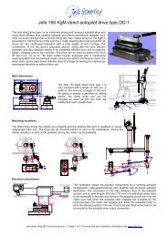
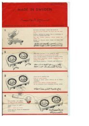
Drive unit in front of pedestal:<br />
When sufficient space around the rudder shaft isn’t<br />
available, the direct drive can be setup to drive the<br />
rudder via the pedestal.<br />
An extra extended output lever with 165 mm centres<br />
can be fitted to the pedestal down-shaft to be driven by<br />
the direct drive.<br />
8°<br />
top view<br />
36°<br />
8°<br />
The lever geometry between the drive and pedestal is<br />
a parallelogram of 165 mm. The pedestal offset angle<br />
has to be respected, so the hole parallelogram is<br />
rotated around the pedestal centre with the offset<br />
angle.<br />
130<br />
165<br />
165<br />
64°<br />
64°<br />
Reducing noise and vibrations:<br />
DIN912 M8x50<br />
Washer Ø8,5 x Ø16<br />
Rubber washer<br />
Drive unit<br />
Rubber washer<br />
Washer Ø8,5 x Ø25<br />
Mounting plate<br />
Nut DIN985 M8<br />
The vibrations from the autopilot drive motor and gears are often amplified multiple times by the deck or hull.<br />
This noise can be dramatically decreased by using the special bolts, rubber washers and bushes one can find in<br />
the bag supplied with the drive unit. When mounted like in the above illustration, the vibrations will be limited to<br />
the absolute minimum and a smooth and silent installation is guaranteed.<br />
Direct drive type I installation guide version 1.3 page 3 of 4