
You also want an ePaper? Increase the reach of your titles
YUMPU automatically turns print PDFs into web optimized ePapers that Google loves.
gab.ru Берг АБ bergab@ya.ru Тел. (495)-228-06-21, факс (495) 22<br />
Y-<strong><strong>bearing</strong>s</strong> <strong>and</strong><br />
Y-<strong>bearing</strong> <strong>units</strong><br />
rgab.ru Берг АБ bergab@ya.ru Тел. (495)-228-06-21, факс (495) 22
gab.ru Берг АБ bergab@ya.ru Тел. (495)-228-06-21, факс (495) 22<br />
® SKF is a registered trademark of the<br />
SKF Group.<br />
© Copyright SKF 2004<br />
The contents of this catalogue are the<br />
copyright of the publisher <strong>and</strong> may not be<br />
reproduced (even extracts) unless permission<br />
is granted. Every care has been taken<br />
to ensure the accuracy of the information<br />
contained in this catalogue but no liability<br />
can be accepted for any loss or damage<br />
whether direct, indirect or consequential<br />
arising out of the use of the information<br />
contained herein.<br />
Catalogue 5001 E · September 2004<br />
Printed in Denmark on environmentally<br />
friendly, chlorine-free paper (G-Print) by<br />
Scanprint as.<br />
rgab.ru Берг АБ bergab@ya.ru Тел. (495)-228-06-21, факс (495) 22
gab.ru Берг АБ bergab@ya.ru Тел. (495)-228-06-21, факс (495) 22<br />
General ……………………………………… 2<br />
Principles of selection <strong>and</strong> application ……… 11<br />
1<br />
2<br />
Y-<strong><strong>bearing</strong>s</strong> …………………………………… 53<br />
3<br />
Y-<strong>bearing</strong> plummer block <strong>units</strong> ……………… 75<br />
4<br />
Y-<strong>bearing</strong> flanged <strong>units</strong> ……………………… 109<br />
5<br />
Y-<strong>bearing</strong> take-up <strong>units</strong>……………………… 161<br />
6<br />
Mounting instructions ……………………… 169<br />
7<br />
Other related SKF products ………………… 197<br />
8<br />
Product index………………………………… 211<br />
9<br />
rgab.ru Берг АБ bergab@ya.ru Тел. (495)-228-06-21, факс (495) 22
gab.ru Берг АБ bergab@ya.ru Тел. (495)-228-06-21, факс (495) 22<br />
Contents<br />
Foreword………………………………………………………………………………………… 5<br />
SKF – The knowledge engineering company……………………………………………… 6<br />
Principles of selection <strong>and</strong> application …………………………………………………… 11<br />
Designs ………………………………………………………………………………………… 12<br />
Bearing terminology ………………………………………………………………………… 13<br />
Matrices ……………………………………………………………………………………… 16<br />
Selection of Y-<strong>bearing</strong> unit type ……………………………………………………………… 18<br />
Locating on the shaft ………………………………………………………………………… 19<br />
Loads ………………………………………………………………………………………… 20<br />
Seals ………………………………………………………………………………………… 21<br />
Permissible operating temperatures ……………………………………………………… 22<br />
Speeds ……………………………………………………………………………………… 23<br />
Application note ……………………………………………………………………………… 23<br />
Selection of Y-<strong>bearing</strong> unit size ……………………………………………………………… 24<br />
Load carrying ability <strong>and</strong> life ………………………………………………………………… 24<br />
Selecting the <strong>bearing</strong> size using the life equations ……………………………………… 24<br />
Equivalent dynamic <strong>bearing</strong> load ………………………………………………………… 26<br />
Dynamic <strong>bearing</strong> loads ……………………………………………………………………… 28<br />
Requisite minimum load …………………………………………………………………… 28<br />
Axial load carrying ability …………………………………………………………………… 28<br />
Selecting the <strong>bearing</strong> size using the static load carrying capacity ……………………… 29<br />
Speeds …………………………………………………………………………………………… 32<br />
Design of Y-<strong>bearing</strong> arrangements …………………………………………………………… 34<br />
Axial displacement ………………………………………………………………………… 34<br />
Initial misalignment ………………………………………………………………………… 36<br />
Support surfaces …………………………………………………………………………… 36<br />
Shaft tolerances ……………………………………………………………………………… 37<br />
Rubber seating rings ………………………………………………………………………… 38<br />
End covers …………………………………………………………………………………… 40<br />
Lubrication <strong>and</strong> maintenance ………………………………………………………………… 42<br />
Grease fills …………………………………………………………………………………… 42<br />
Relubrication ………………………………………………………………………………… 43<br />
Relubrication intervals ……………………………………………………………………… 44<br />
Storing Y-<strong><strong>bearing</strong>s</strong> <strong>and</strong> Y-<strong>bearing</strong> <strong>units</strong> ……………………………………………………… 46<br />
Designation systems …………………………………………………………………………… 47<br />
2<br />
rgab.ru Берг АБ bergab@ya.ru Тел. (495)-228-06-21, факс (495) 22
gab.ru Берг АБ bergab@ya.ru Тел. (495)-228-06-21, факс (495) 22<br />
1<br />
Product data …………………………………………………………………………………… 51<br />
Y-<strong><strong>bearing</strong>s</strong> ……………………………………………………………………………………… 53<br />
Y-<strong>bearing</strong> plummer block <strong>units</strong> ………………………………………………………………… 75<br />
Y-<strong>bearing</strong> flanged <strong>units</strong> ………………………………………………………………………… 109<br />
Y-<strong>bearing</strong> take-up <strong>units</strong> ………………………………………………………………………… 161<br />
Mounting instructions ………………………………………………………………………… 169<br />
Other related SKF products ………………………………………………………………… 197<br />
Product index…………………………………………………………………………………… 211<br />
3<br />
rgab.ru Берг АБ bergab@ya.ru Тел. (495)-228-06-21, факс (495) 22
gab.ru Берг АБ bergab@ya.ru Тел. (495)-228-06-21, факс (495) 22<br />
The SKF br<strong>and</strong> now st<strong>and</strong>s for more<br />
than ever before, <strong>and</strong> means more to<br />
you as a valued customer.<br />
While SKF maintains its leadership<br />
as the hallmark of quality <strong><strong>bearing</strong>s</strong><br />
throughout the world, new dimensions<br />
in technical advances, product support<br />
<strong>and</strong> services have evolved SKF into<br />
a truly solutions-oriented supplier,<br />
creating greater value for customers.<br />
These solutions encompass ways<br />
to bring greater productivity to customers,<br />
not only with breakthrough<br />
application-specific products, but also<br />
through leading-edge design simulation<br />
tools <strong>and</strong> consultancy services, plant<br />
asset efficiency maintenance programmes,<br />
<strong>and</strong> the industry’s most<br />
advanced supply management<br />
techniques.<br />
The SKF br<strong>and</strong> still st<strong>and</strong>s for the very<br />
best in rolling <strong><strong>bearing</strong>s</strong>, but it now st<strong>and</strong>s<br />
for much more.<br />
SKF – The knowledge engineering<br />
company<br />
4<br />
rgab.ru Берг АБ bergab@ya.ru Тел. (495)-228-06-21, факс (495) 22
gab.ru Берг АБ bergab@ya.ru Тел. (495)-228-06-21, факс (495) 22<br />
Foreword<br />
1<br />
This catalogue gives a representative overview<br />
of the range of Y-<strong><strong>bearing</strong>s</strong> <strong>and</strong> Y-<strong>bearing</strong><br />
<strong>units</strong> available from SKF. Compared with<br />
the previous SKF catalogue 4002, this catalogue<br />
contains considerable alterations <strong>and</strong><br />
the assortment has been brought up to date.<br />
The data in this catalogue is based on the<br />
latest st<strong>and</strong>ards <strong>and</strong> product upgrades.<br />
However, SKF reserves the right to make any<br />
changes necessary as a result of continuous<br />
improvement with respect to materials,<br />
design <strong>and</strong> manufacture.<br />
In accordance with ISO St<strong>and</strong>ard<br />
1000:1992, SI (Système International<br />
d’Unités) <strong>units</strong> are used in this catalogue.<br />
This catalogue contains all the data relevant<br />
to Y-<strong><strong>bearing</strong>s</strong> <strong>and</strong> Y-<strong>bearing</strong> <strong>units</strong>. All<br />
the data required to select a Y-<strong>bearing</strong> or<br />
Y-<strong>bearing</strong> unit respectively are listed in the<br />
product tables. Descriptions of the Y-<strong>bearing</strong><br />
<strong>and</strong> Y-<strong>bearing</strong> unit types including design<br />
features <strong>and</strong> other information precede<br />
each product section. General data regarding<br />
selecting a Y-<strong>bearing</strong> or Y-<strong>bearing</strong> unit<br />
type <strong>and</strong> size, speeds, <strong>bearing</strong> arrangement<br />
design, lubrication, mounting <strong>and</strong> designations<br />
are included in the catalogue too.<br />
The catalogue is designed so that product<br />
information is easy to find <strong>and</strong> use. Each of<br />
the 9 chapters listed in the table of contents<br />
is clearly identified by a number <strong>and</strong> colour.<br />
5<br />
rgab.ru Берг АБ bergab@ya.ru Тел. (495)-228-06-21, факс (495) 22
gab.ru Берг АБ bergab@ya.ru Тел. (495)-228-06-21, факс (495) 22<br />
SKF – The knowledge<br />
engineering company<br />
The business of the SKF Group consists of<br />
the design, manufacture <strong>and</strong> marketing of<br />
the world’s leading br<strong>and</strong> of rolling <strong><strong>bearing</strong>s</strong>,<br />
with a global leadership position in complementary<br />
products such as radial seals. SKF<br />
also holds an increasingly important position<br />
in the market for linear motion products, high<br />
precision aerospace <strong><strong>bearing</strong>s</strong>, machine tool<br />
spindles as well as plant maintenance services<br />
<strong>and</strong> is an established producer of<br />
high-quality <strong>bearing</strong> steel.<br />
The SKF Group maintains specialized<br />
business operations to meet the needs of the<br />
global marketplace. SKF supports specific<br />
market segments with ongoing research <strong>and</strong><br />
development efforts that have led to a growing<br />
number of innovations, new st<strong>and</strong>ards<br />
<strong>and</strong> new products.<br />
The Group has global ISO 14001 environmental<br />
certification. Individual divisions have<br />
been approved for quality certification in<br />
accordance with either ISO 9000 or appropriate<br />
industry specific st<strong>and</strong>ards.<br />
Some 80 manufacturing sites worldwide<br />
<strong>and</strong> sales companies in 70 countries make<br />
SKF a truly international corporation. In<br />
addition, our 7 000 distributor <strong>and</strong> dealer<br />
partners around the world, e-business<br />
marketplace <strong>and</strong> global distribution system<br />
put SKF close to customers for the supply<br />
of both products <strong>and</strong> services. In essence,<br />
SKF solutions are available wherever <strong>and</strong><br />
whenever our customers need them.<br />
Overall, the SKF br<strong>and</strong> now st<strong>and</strong>s for<br />
more than ever before. It st<strong>and</strong>s for the<br />
knowledge engineering company ready to<br />
serve you with world-class product competences,<br />
intellectual resources <strong>and</strong> the vision<br />
to help you succeed.<br />
6<br />
rgab.ru Берг АБ bergab@ya.ru Тел. (495)-228-06-21, факс (495) 22
gab.ru Берг АБ bergab@ya.ru Тел. (495)-228-06-21, факс (495) 22<br />
1<br />
Evolving by-wire technology<br />
SKF has unique expertise <strong>and</strong> knowledge in fast-growing by-wire technology,<br />
from fly-by-wire, to drive-by-wire, to work-by-wire. SKF pioneered<br />
practical fly-by-wire technology <strong>and</strong> is a close working partner<br />
with all aerospace industry leaders. As an example, virtually all aircraft of<br />
the Airbus design use SKF by-wire systems for cockpit flight control.<br />
3<br />
SKF is also a leader in automotive<br />
drive-by-wire, having jointly developed<br />
the revolutionary Filo <strong>and</strong> Novanta<br />
concept cars which employ SKF<br />
mechatronics for steering <strong>and</strong> braking.<br />
Further by-wire development has led<br />
SKF to produce an all-electric forklift<br />
truck which uses mechatronics rather<br />
than hydraulics for all controls.<br />
7<br />
rgab.ru Берг АБ bergab@ya.ru Тел. (495)-228-06-21, факс (495) 22
gab.ru Берг АБ bergab@ya.ru Тел. (495)-228-06-21, факс (495) 22<br />
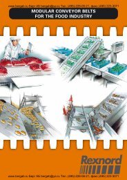
Delivering asset efficiency optimization<br />
To optimize efficiency <strong>and</strong> boost productivity,<br />
many industrial facilities outsource some or<br />
all of their maintenance services to SKF,<br />
often with guaranteed performance<br />
contracts. Through the specialized<br />
capabilities <strong>and</strong> knowledge available<br />
from SKF Reliability Systems, SKF provides<br />
a comprehensive range of asset<br />
efficiency services, from maintenance<br />
strategies <strong>and</strong> engineering assistance,<br />
to operator-driven reliability <strong>and</strong> machine<br />
maintenance programmes.<br />
Planning for sustainable growth<br />
By their very nature, <strong><strong>bearing</strong>s</strong> make a positive<br />
contribution to the natural environment. Reduced<br />
friction enables machinery to operate more efficiently,<br />
consume less power <strong>and</strong> require less lubrication.<br />
SKF is continually raising the performance<br />
bar, enabling a new generation of high-efficiency<br />
products <strong>and</strong> equipment. With an eye to the<br />
future, SKF’s global policies <strong>and</strong> manufacturing<br />
techniques are planned <strong>and</strong> implemented to help<br />
protect <strong>and</strong> preserve the earth’s limited natural<br />
resources. We remain committed to sustainable,<br />
environmentally responsible growth.<br />
Maintaining a 320 km/h R&D lab<br />
In addition to SKF’s renowned research <strong>and</strong> development facilities in Europe <strong>and</strong> the<br />
United States, Formula One car racing provides a unique environment for SKF to push<br />
the limits of <strong>bearing</strong> technology. For over 50 years, SKF products, engineering <strong>and</strong><br />
knowledge have helped make Scuderia Ferrari a formidable force in F1 racing. (The<br />
average racing Ferrari utilizes more than 150 SKF components.) Lessons learned here<br />
are applied to the products we provide to automakers <strong>and</strong> the aftermarket worldwide.<br />
8<br />
rgab.ru Берг АБ bergab@ya.ru Тел. (495)-228-06-21, факс (495) 22
gab.ru Берг АБ bergab@ya.ru Тел. (495)-228-06-21, факс (495) 22<br />
Developing a cleaner cleaner<br />
The electric motor <strong>and</strong> its <strong><strong>bearing</strong>s</strong> are the heart of<br />
many household appliances. SKF works closely<br />
with appliance manufacturers to improve their<br />
product performance, cut costs, reduce<br />
weight, etc. A recent example produced<br />
a new generation of vacuum cleaners with<br />
substantially more suction. SKF’s knowledge<br />
in small <strong>bearing</strong> technology is also applied to<br />
manufacturers of power tools <strong>and</strong> office equipment.<br />
1<br />
Creating a new “cold remedy”<br />
In the frigid winters of northern China,<br />
sub-zero temperatures can cause rail car<br />
wheel assemblies <strong>and</strong> their <strong><strong>bearing</strong>s</strong> to<br />
seize due to lubrication starvation. SKF<br />
created a new family of synthetic lubricants<br />
formulated to retain their lubrication viscosity<br />
even at these extreme <strong>bearing</strong> temperatures.<br />
SKF’s knowledge of lubricants <strong>and</strong><br />
friction are unmatched in the world.<br />
Harnessing wind power<br />
The growing industry of wind-generated electric<br />
power provides an environmentally compatible<br />
source of electricity. SKF is working closely<br />
with global industry leaders to develop efficient<br />
<strong>and</strong> trouble-free turbines, using SKF knowledge<br />
to provide highly specialized <strong><strong>bearing</strong>s</strong><br />
<strong>and</strong> condition monitoring systems to extend<br />
equipment life in the extreme <strong>and</strong> often remote<br />
environments of wind farms.<br />
9<br />
rgab.ru Берг АБ bergab@ya.ru Тел. (495)-228-06-21, факс (495) 22
gab.ru Берг АБ bergab@ya.ru Тел. (495)-228-06-21, факс (495) 22<br />
rgab.ru Берг АБ bergab@ya.ru Тел. (495)-228-06-21, факс (495) 22
gab.ru Берг АБ bergab@ya.ru Тел. (495)-228-06-21, факс (495) 22<br />
Principles of selection<br />
<strong>and</strong> application<br />
2<br />
Designs ………………………………………………………………………………………… 12<br />
Selection of Y-<strong>bearing</strong> unit type …………………………………………………………… 18<br />
Selection of Y-<strong>bearing</strong> unit size …………………………………………………………… 24<br />
Speeds ………………………………………………………………………………………… 32<br />
Design of Y-<strong>bearing</strong> arrangements ………………………………………………………… 34<br />
Lubrication <strong>and</strong> maintenance ……………………………………………………………… 42<br />
Storing Y-<strong><strong>bearing</strong>s</strong> <strong>and</strong> Y-<strong>bearing</strong> <strong>units</strong> …………………………………………………… 46<br />
Designation systems ………………………………………………………………………… 47<br />
11<br />
rgab.ru Берг АБ bergab@ya.ru Тел. (495)-228-06-21, факс (495) 22
gab.ru Берг АБ bergab@ya.ru Тел. (495)-228-06-21, факс (495) 22<br />
Designs<br />
Conventional SKF ball <strong>bearing</strong> <strong>units</strong> are<br />
referred to as Y-<strong>bearing</strong> <strong>units</strong>. These <strong>units</strong><br />
consist of<br />
• an insert <strong>bearing</strong> (a single row deep<br />
groove ball <strong>bearing</strong>) with a convex<br />
sphered outside diameter <strong>and</strong><br />
• a housing which has a correspondingly<br />
sphered but concave bore.<br />
Y-<strong>bearing</strong> <strong>units</strong> can accommodate moderate<br />
initial misalignment, but normally do not<br />
permit axial displacement. They are readyto-mount,<br />
ready-to-use <strong>units</strong> (➔ fig 1 ) <strong>and</strong><br />
available as<br />
• Y-<strong>bearing</strong> plummer block <strong>units</strong>,<br />
• Y-<strong>bearing</strong> flanged <strong>units</strong> <strong>and</strong><br />
• Y-<strong>bearing</strong> take-up <strong>units</strong>.<br />
The housings are available in the following<br />
materials:<br />
• composite material referred to as<br />
Y-TECH (➔ fig 2 ),<br />
• grey cast iron (➔ fig 3 ) or<br />
• sheet steel (➔ fig 4 ).<br />
Fig<br />
Fig<br />
1<br />
2<br />
SKF Y-<strong>bearing</strong> <strong>units</strong> provide designers with<br />
considerable freedom of choice so that<br />
compromises can be avoided. Some 40<br />
st<strong>and</strong>ard series Y-<strong>bearing</strong> <strong>units</strong> are available<br />
(➔ matrices on pages 16 <strong>and</strong> 17).<br />
Because of their versatility, <strong>and</strong> cost<br />
effectiveness, Y-<strong>bearing</strong> <strong>units</strong> are typically<br />
12<br />
rgab.ru Берг АБ bergab@ya.ru Тел. (495)-228-06-21, факс (495) 22
gab.ru Берг АБ bergab@ya.ru Тел. (495)-228-06-21, факс (495) 22<br />
found in the following applications: agricultural<br />
machinery, construction equipment,<br />
conveyor systems, textile machines <strong>and</strong><br />
fans as well as in machines for food <strong>and</strong><br />
beverage processing <strong>and</strong> packaging.<br />
Fig<br />
3<br />
Bearing terminology<br />
To better underst<strong>and</strong> frequently used <strong>bearing</strong><br />
specific terms for<br />
2<br />
• Y-<strong><strong>bearing</strong>s</strong>,<br />
• Y-<strong>bearing</strong> plummer block <strong>units</strong>,<br />
• Y-<strong>bearing</strong> flanged <strong>units</strong>,<br />
• Y-<strong>bearing</strong> take-up <strong>units</strong>,<br />
the terms <strong>and</strong> their definitions are provided<br />
on pages 14 <strong>and</strong> 15. Essentially these terms<br />
conform to those found in the following ISO<br />
st<strong>and</strong>ards:<br />
• ISO 3228:1993 “Rolling <strong><strong>bearing</strong>s</strong> – Cast<br />
<strong>and</strong> pressed housings for insert <strong><strong>bearing</strong>s</strong>”.<br />
• ISO 9628:1992 “Rolling <strong><strong>bearing</strong>s</strong> – Insert.<br />
<strong><strong>bearing</strong>s</strong> <strong>and</strong> eccentric locking collars”.<br />
A detailed collection of <strong>bearing</strong> specific<br />
terms <strong>and</strong> definitions can be found in<br />
ISO 5593:1997 “Rolling <strong><strong>bearing</strong>s</strong> –<br />
Vocabulary”.<br />
Fig<br />
4<br />
13<br />
rgab.ru Берг АБ bergab@ya.ru Тел. (495)-228-06-21, факс (495) 22
gab.ru<br />
Designs<br />
Берг АБ bergab@ya.ru Тел. (495)-228-06-21, факс (495) 22<br />
3<br />
2<br />
1<br />
11<br />
5<br />
10 6<br />
Inner ring with eccentric locking collar<br />
Fig<br />
4<br />
7<br />
8<br />
9<br />
5<br />
Y-<strong>bearing</strong> (➔ fig 5 )<br />
1 Outer ring<br />
2 Sphered outer surface<br />
3 Lubrication hole<br />
4 Inner ring<br />
5 Bore<br />
6 Cage<br />
7 Ball<br />
8 Superagriseal<br />
9 Flinger<br />
10 Eccentric locking collar<br />
11 Grub screw<br />
Y-<strong>bearing</strong> plummer block unit (➔ fig 6 )<br />
1 Y-<strong>bearing</strong> plummer (pillow) block housing<br />
of grey cast iron<br />
2 Housing base<br />
3 Housing support face<br />
4 Cast dimple for dowel pin<br />
5 Attachment bolt hole<br />
6 Y-<strong>bearing</strong> (➔ fig 5 )<br />
7 Grease nipple<br />
8 Recess for end cover<br />
9 Filling slot for Y-<strong>bearing</strong><br />
Inner ring with two grub screws<br />
Fig<br />
6<br />
6<br />
7<br />
Inner ring with tapered bore<br />
(on adapter sleeve)<br />
8<br />
9<br />
4<br />
5<br />
3<br />
2<br />
1<br />
Inner ring of st<strong>and</strong>ard deep<br />
groove ball <strong>bearing</strong><br />
14<br />
rgab.ru Берг АБ bergab@ya.ru Тел. (495)-228-06-21, факс (495) 22
gab.ru Берг АБ bergab@ya.ru Тел. (495)-228-06-21, факс (495) 22<br />
Y-<strong>bearing</strong> flanged unit (➔ fig 7 )<br />
Fig<br />
7<br />
1 Square flanged housing of grey cast iron<br />
2 Attachment bolt hole<br />
3 Back of flanged housing with or without<br />
centring recess<br />
4 Cast dimple for dowel pin<br />
5 Y-<strong>bearing</strong> (➔ fig 5 )<br />
6 Grease nipple<br />
7 Filling slot for Y-<strong>bearing</strong><br />
8 Recess for end cover<br />
5<br />
6<br />
7<br />
2<br />
4<br />
8<br />
3<br />
2<br />
1<br />
Y-<strong>bearing</strong> take-up unit (➔ fig 8 )<br />
Fig<br />
8<br />
1 Take-up housing of grey cast iron<br />
2 Grease nipple<br />
3 Y-<strong>bearing</strong> (➔ fig 5 )<br />
4 Piloting groove<br />
5 Recess for end cover<br />
6 Receiving opening for adjustment screw<br />
location<br />
7 Centre bore for adjustment screw<br />
8 Filling slot for Y-<strong>bearing</strong><br />
3<br />
4<br />
5 6<br />
2<br />
1<br />
8<br />
7<br />
15<br />
rgab.ru Берг АБ bergab@ya.ru Тел. (495)-228-06-21, факс (495) 22
gab.ru<br />
Designs<br />
Берг АБ bergab@ya.ru Тел. (495)-228-06-21, факс (495) 22<br />
Y-<strong>bearing</strong> unit<br />
Y-<strong>bearing</strong> housings<br />
Y-<strong><strong>bearing</strong>s</strong><br />
YAR 2-2F<br />
SYK 5(00)<br />
SYKC 5(00) N<br />
SYK .. TF<br />
20 – 40 mm<br />
3 /4 – 1 1 /2 in<br />
SY 5(00) M<br />
SYJ 5(00)<br />
SY .. TF<br />
SYJ .. TF<br />
12 – 100 mm<br />
3 /4 – 2 1 /2 in<br />
SYF 5(00) M<br />
SYFJ 5(00)<br />
SYF .. TF<br />
SYFJ .. TF<br />
20 – 50 mm<br />
3 /4 – 1 3 /4 in<br />
P 40 – 85 FYK 5(00)<br />
FYKC 5(00) N<br />
Parts<br />
must be<br />
ordered<br />
separately<br />
12 – 45 mm<br />
3 /4 – 1 3 /4 in<br />
FYK .. TF<br />
20 – 40 mm<br />
3 /4 – 1 1 /2 in<br />
FYTBK 5(00)<br />
FYTBKC 5(00)N<br />
FYTBK .. TF<br />
20 – 35 mm<br />
3 /4 – 1 1 /4 in<br />
YAR 2-2RF<br />
SYK .. TR<br />
20 – 40 mm<br />
3 /4 – 1 1 /2 in<br />
SY .. TR<br />
20 – 60 m<br />
3 /4 – 2 1 /2 in<br />
Parts<br />
must be<br />
ordered<br />
separately<br />
20 – 50 mm<br />
3 /4 – 1 3 /4 in<br />
Parts<br />
must be<br />
ordered<br />
separately<br />
20 – 45 mm<br />
3 /4 – 1 3 /4 in<br />
FYK .. TR<br />
20 – 40 mm<br />
3 /4 – 1 1 /2 in<br />
FYTBK .. TR<br />
20 – 35 mm<br />
3 /4 – 1 1 /4 in<br />
YAR 2-2RF/HV<br />
SYKC .. NTH<br />
20 – 40 mm<br />
3 /4 – 1 1 /2 in<br />
Parts<br />
must be<br />
ordered<br />
separately<br />
20 – 40 mm<br />
3 /4 – 1 1 /2 in<br />
Parts<br />
must be<br />
ordered<br />
separately<br />
20 – 40 mm<br />
3 /4 – 1 1 /2 in<br />
Parts<br />
must be<br />
ordered<br />
separately<br />
20 – 40 mm<br />
3 /4 – 1 1 /2 in<br />
FYKC .. NTH<br />
20 – 40 mm<br />
3 /4 – 1 1 /2 in<br />
FYTBKC .. NTH<br />
20 – 35 mm<br />
3 /4 – 1 1 /4 in<br />
YAR 2-2RF/VE495<br />
Parts must be ordered<br />
separately<br />
20 – 40 mm 20 – 40 mm 20 – 40 mm 20 – 40 mm 20 – 40 mm 20 – 35 mm<br />
YAT 2<br />
Parts must be ordered<br />
separately<br />
20 – 40 mm 17 – 50 mm 20 – 50 mm 17 – 45 mm 20 – 40 mm 20 – 35 mm<br />
YEL 2-2F<br />
Parts<br />
must be<br />
ordered<br />
separately<br />
20 – 40 mm<br />
SY .. WF<br />
20 – 60 mm<br />
Parts<br />
must be<br />
ordered<br />
separately<br />
20 – 50 mm<br />
Parts<br />
must be<br />
ordered<br />
separately<br />
20 – 45 mm<br />
Parts<br />
must be<br />
ordered<br />
separately<br />
20 – 40 mm<br />
Parts<br />
must be<br />
ordered<br />
separately<br />
20 – 35 mm<br />
YEL 2-2RF/VL065<br />
Parts must be ordered<br />
separately<br />
20 – 40 mm 20 – 40 mm 20 – 40 mm 20 – 40 mm 20 – 40 mm 20 – 35 mm<br />
YET 2<br />
Parts<br />
must be<br />
ordered<br />
separately<br />
20 – 40 mm<br />
3 /4 – 1 1 /2 in<br />
SY .. FM<br />
15 – 60 mm<br />
3 /4 – 1 1 /2 in<br />
SYF .. FM<br />
20 – 50 mm<br />
3 /4 – 1 1 /2 in<br />
Parts<br />
must be<br />
ordered<br />
separately<br />
15 – 45 mm<br />
3 /4 – 1 1 /2 in<br />
Parts<br />
must be<br />
ordered<br />
separately<br />
20 – 40 mm<br />
3 /4 – 1 1 /2 in<br />
Parts<br />
must be<br />
ordered<br />
separately<br />
20 – 35 mm<br />
3 /4 – 1 in<br />
YSA 2-2FK on<br />
adapter sleeve<br />
Parts<br />
must be<br />
ordered<br />
separately<br />
20 – 35 mm<br />
3 /4 – 1 1 /4 in<br />
SYJ .. KF<br />
20 – 60 mm<br />
3 /4 – 2 3 /8 in<br />
Parts<br />
must be<br />
ordered<br />
separately<br />
20 – 45 mm<br />
3 /4 – 1 3 /4 in<br />
Parts<br />
must be<br />
ordered<br />
separately<br />
20 – 40 mm<br />
3 /4 – 1 3 /4 in<br />
Parts<br />
must be<br />
ordered<br />
separately<br />
20 – 35 mm<br />
3 /4 – 1 1 /4 in<br />
Parts<br />
must be<br />
ordered<br />
separately<br />
20 – 30 mm<br />
3 /4 – 1 1 /8 in<br />
17262(00)<br />
Parts must be ordered<br />
separately<br />
20 – 40 mm 20 – 60 mm 20 – 50 mm 17 – 45 mm 20 – 40 mm 20 – 35 mm<br />
16<br />
rgab.ru Берг АБ bergab@ya.ru Тел. (495)-228-06-21, факс (495) 22
gab.ru Берг АБ bergab@ya.ru Тел. (495)-228-06-21, факс (495) 22<br />
FY 5(00) M<br />
FYJ 5(00)<br />
FY .. TF<br />
FYJ .. TF<br />
12 – 100 mm<br />
3 /4 – 2 1 /2 in<br />
FY .. TR<br />
20 – 65 mm<br />
3 /4 – 2 1 /2 in<br />
FYTB 5(00) M<br />
FYTJ 5(00)<br />
FYTB .. TF<br />
FYTJ .. TF<br />
12 – 50 mm<br />
3 /4 – 1 3 /4 in<br />
FYTB .. TR<br />
20 – 50 mm<br />
3 /4 – 1 3 /4 in<br />
FYC 5(00) PF 40 – 90 PFD 40 – 80 PFT 40 – 80 TU 5(00) M<br />
TUJ 5(00)<br />
FYC .. TF<br />
20 – 65 mm<br />
3 /4 – 2 1 /2 in<br />
Parts<br />
must be<br />
ordered<br />
separately<br />
20 – 65 mm<br />
3 /4 – 2 1 /2 in<br />
Parts<br />
must be<br />
ordered<br />
separately<br />
12 – 50 mm<br />
3 /4 – 1 3 /4 in<br />
Parts<br />
must be<br />
ordered<br />
separately<br />
20 – 50 mm<br />
3 /4 – 1 3 /4 in<br />
Parts<br />
must be<br />
ordered<br />
separately<br />
12 – 40 mm<br />
3 /4 – 1 1 /2 in<br />
Parts<br />
must be<br />
ordered<br />
separately<br />
20 – 40 mm<br />
3 /4 – 1 1 /2 in<br />
Parts<br />
must be<br />
ordered<br />
separately<br />
12 – 40 mm<br />
3 /4 – 1 1 /2 in<br />
Parts<br />
must be<br />
ordered<br />
separately<br />
20 – 40 mm<br />
3 /4 – 1 1 /2 in<br />
TU .. TF<br />
TUJ .. TF<br />
20 – 60 mm<br />
1 – 2 in<br />
Parts<br />
must be<br />
ordered<br />
separately<br />
20 – 60 mm<br />
3 /4 – 2 in<br />
2<br />
Parts must be ordered<br />
separately<br />
20 – 40 mm<br />
3 /4 – 1 1 /2 in<br />
20 – 40 mm<br />
3 /4 – 1 1 /2 in<br />
20 – 40 mm<br />
3 /4 – 1 1 /2 in<br />
20 – 40 mm<br />
3 /4 – 1 1 /2 in<br />
20 – 40 mm<br />
3 /4 – 1 1 /2 in<br />
20 – 40 mm<br />
3 /4 – 1 1 /2 in<br />
20 – 40 mm<br />
3 /4 – 1 1 /2 in<br />
Parts must be ordered<br />
separately<br />
20 – 40 mm<br />
20 – 40 mm 20 – 40 mm 20 – 40 mm 20 – 40 mm 20 – 40 mm 20 – 40 mm<br />
Parts must be ordered<br />
separately<br />
17 – 50 mm<br />
17 – 50 mm 20 – 50 mm 17 – 50 mm 17 – 40 mm 17 – 40 mm 20 – 50 mm<br />
FY .. WF<br />
20 – 60 mm<br />
FYTB .. WF<br />
20 – 50 mm<br />
Parts<br />
must be<br />
ordered<br />
separately<br />
20 – 60 mm<br />
Parts<br />
must be<br />
ordered<br />
separately<br />
20 – 50 mm<br />
Parts<br />
must be<br />
ordered<br />
separately<br />
20 – 40 mm<br />
Parts<br />
must be<br />
ordered<br />
separately<br />
20 – 40 mm<br />
Parts<br />
must be<br />
ordered<br />
separately<br />
20 – 60 mm<br />
Parts must be ordered<br />
separately<br />
20 – 40 mm<br />
20 – 40 mm 20 – 40 mm 20 – 40 mm 20 – 40 mm 20 – 40 mm 20 – 40 mm<br />
FY .. FM<br />
15 – 60 mm<br />
3 /4 – 1 1 /2 in<br />
FYTB – FM<br />
15 – 50 mm<br />
3 /4 – 1 1 /2 in<br />
Parts<br />
must be<br />
ordered<br />
separately<br />
20 – 60 mm<br />
3 /4 – 1 1 /2 in<br />
Parts<br />
must be<br />
ordered<br />
separately<br />
15 – 50 mm<br />
3 /4 – 1 1 /2 in<br />
Parts<br />
must be<br />
ordered<br />
separately<br />
15 – 40 mm<br />
3 /4 – 1 1 /2 in<br />
Parts<br />
must be<br />
ordered<br />
separately<br />
15 – 40 mm<br />
3 /4 – 1 1 /2 in<br />
TU .. FM<br />
20 – 55 mm<br />
FYJ .. KF<br />
20 – 60 mm<br />
3 /4 – 2 3 /8 in<br />
FYTJ .. KF<br />
20 – 45 mm<br />
3 /4 – 1 3 /4 in<br />
Parts<br />
must be<br />
ordered<br />
separately<br />
20 – 60 mm<br />
3 /4 – 2 3 /8 in<br />
Parts<br />
must be<br />
ordered<br />
separately<br />
20 – 45 mm<br />
3 /4 – 1 3 /4 in<br />
Parts<br />
must be<br />
ordered<br />
separately<br />
20 – 35 mm<br />
3 /4 – 1 3 /16 in<br />
Parts<br />
must be<br />
ordered<br />
separately<br />
20 – 35 mm<br />
3 /4 – 1 3 /16 in<br />
Parts<br />
must be<br />
ordered<br />
separately<br />
20 – 55 mm<br />
3 /4 – 2 1 /8 in<br />
Parts must be ordered<br />
separately<br />
17 – 60 mm<br />
20 – 50 mm 20 – 60 mm 17 – 50 mm 17 – 40 mm 17 – 40 mm 20 – 60 mm<br />
17<br />
rgab.ru Берг АБ bergab@ya.ru Тел. (495)-228-06-21, факс (495) 22
gab.ru Берг АБ bergab@ya.ru Тел. (495)-228-06-21, факс (495) 22<br />
Selection of Y-<strong>bearing</strong><br />
unit type<br />
The SKF Y-<strong>bearing</strong> unit product range is extensive.<br />
It includes three designs with housings<br />
made from three different materials <strong>and</strong><br />
a variety of Y-<strong><strong>bearing</strong>s</strong> that can be locked<br />
onto the shaft in very different ways. Because<br />
of their design, each Y-<strong>bearing</strong> unit exhibits<br />
characteristic features that make it more<br />
or less suitable for a specific application.<br />
For example, Y-<strong>bearing</strong> <strong>units</strong> with a pressed<br />
steel housing are not capable of supporting<br />
heavy loads, can only run at moderate speeds<br />
<strong>and</strong> can not be relubricated. However, they<br />
are economical <strong>and</strong> easy to mount. On the<br />
other h<strong>and</strong>, housings made of cast iron can<br />
withst<strong>and</strong> significantly heavier radial, axial<br />
<strong>and</strong> shock loads. In addition, cast iron housings<br />
have a grease nipple for relubrication,<br />
making them an excellent choice for high<br />
speed applications.<br />
Since in many cases the selection of<br />
a suitable Y-<strong>bearing</strong> unit must take many<br />
factors into consideration, there is no way to<br />
provide a list of general rules. The following<br />
notes should show, however, what factors<br />
are the most important ones to consider<br />
first:<br />
Keep in mind that the total cost of a <strong>bearing</strong><br />
arrangement <strong>and</strong> inventory considerations<br />
could also influence the final choice.<br />
Other important criteria for designing a<br />
<strong>bearing</strong> arrangement, such as load carrying<br />
capacity <strong>and</strong> rating life, lubrication, etc., will<br />
be dealt with in detail in the corresponding<br />
chapters.<br />
• Locating on the shaft<br />
• Loads<br />
• Seals<br />
• Permissible operating temperatures<br />
• Speeds<br />
18<br />
rgab.ru Берг АБ bergab@ya.ru Тел. (495)-228-06-21, факс (495) 22
gab.ru Берг АБ bergab@ya.ru Тел. (495)-228-06-21, факс (495) 22<br />
Fig<br />
1<br />
Locating on the shaft<br />
There is a choice of four different methods<br />
(➔ fig 1 ) by which an SKF Y-<strong>bearing</strong> unit<br />
can be located onto the shaft:<br />
a<br />
b<br />
• Grub (set) screws (a). This method enables<br />
very easy mounting <strong>and</strong> dismounting,<br />
even if space is limited. This locking<br />
method is typically used in applications<br />
where the shaft alternates direction of<br />
rotation.<br />
• Eccentric locking collar (b). This locking<br />
method should be chosen for applications<br />
where the shaft rotates in one direction<br />
only.<br />
• Adapter sleeve locking (c). This method<br />
enables a concentric locking of the Y-<strong>bearing</strong><br />
unit on the shaft <strong>and</strong> is appropriate for<br />
alternating as well as constant directions<br />
of rotation.<br />
• Interference fit (d). The use of an interference<br />
fit is only available for Y-<strong><strong>bearing</strong>s</strong> in<br />
the 17262(00)-2RS1 <strong>and</strong> 17263(00)-2RS1<br />
series. These <strong><strong>bearing</strong>s</strong> <strong>and</strong> the required<br />
housings have to be ordered separately.<br />
2<br />
c<br />
d<br />
19<br />
rgab.ru Берг АБ bergab@ya.ru Тел. (495)-228-06-21, факс (495) 22
gab.ru<br />
Selection<br />
Берг<br />
of<br />
АБ<br />
Y-<strong>bearing</strong><br />
bergab@ya.ru<br />
unit type<br />
Тел. (495)-228-06-21, факс (495) 22<br />
Loads<br />
The magnitude of the load is the factor that<br />
usually determines the size of the Y-<strong>bearing</strong><br />
unit to be used. Generally, <strong>units</strong> with housings<br />
made from cast iron or composite<br />
material can withst<strong>and</strong> heavier loads than<br />
<strong>units</strong> with pressed sheet steel housings.<br />
Radial loads<br />
In applications where moderate <strong>and</strong> heavy<br />
loads occur, only Y-<strong>bearing</strong> <strong>units</strong> with housings<br />
made from cast iron or composite<br />
material should be used. These <strong>units</strong> are<br />
able to withst<strong>and</strong> the same dynamic <strong>and</strong><br />
static loads as their insert <strong><strong>bearing</strong>s</strong> <strong>and</strong> are<br />
less sensitive to shock loads (➔ fig 2a ).<br />
Y-<strong>bearing</strong> <strong>units</strong> with a pressed steel housing<br />
are designed to withst<strong>and</strong> light to moderate<br />
loads <strong>and</strong> are not able to accommodate<br />
shock loads (➔ fig 2b ).<br />
Fig<br />
2<br />
Axial loads<br />
The axial load carrying capacity of a Y-<strong>bearing</strong><br />
depends not as much on its internal design<br />
as on the way it is locked onto the shaft<br />
(➔ fig 2c ); ➔ chapter “Axial load carrying<br />
ability”, page 28. In general, Y-<strong>bearing</strong> <strong>units</strong><br />
with housings made from cast iron or composite<br />
material are more suitable for heavier<br />
or alternating axial loads.<br />
Y-<strong>bearing</strong> <strong>units</strong> with a pressed sheet steel<br />
housing are only intended for moderate axial<br />
loads, in particular the plummer block <strong>units</strong><br />
incorporating a rubber seating ring (➔ fig 2d ).<br />
a<br />
a<br />
b<br />
b<br />
c<br />
c<br />
d<br />
d<br />
20<br />
rgab.ru Берг АБ bergab@ya.ru Тел. (495)-228-06-21, факс (495) 22
gab.ru Берг АБ bergab@ya.ru Тел. (495)-228-06-21, факс (495) 22<br />
Fig<br />
3<br />
Seals<br />
The factors that influence the choice of the<br />
most appropriate seal include:<br />
• The peripheral speed at the sealing<br />
counterface.<br />
• The friction in the seal <strong>and</strong> the resulting<br />
temperature increase.<br />
• The operating environment, e.g. moisture,<br />
dust or coarse contaminants.<br />
• The requirements regarding efficiency.<br />
2<br />
a<br />
b<br />
The st<strong>and</strong>ard “Superagriseal” used in SKF<br />
Y-<strong>bearing</strong> <strong>units</strong> provides good protection<br />
against moisture <strong>and</strong> contaminants <strong>and</strong> also<br />
provides reliable retention of the lubricant<br />
(➔ fig 3a ). The same applies to RS1 contact<br />
seals that are built into the Y-<strong><strong>bearing</strong>s</strong> with<br />
normal inner ring, series 17262(00)-2RS1<br />
<strong>and</strong> 17263(00)-2RS1 (➔ fig 3b ).<br />
For more contaminated conditions<br />
Y-<strong>bearing</strong> <strong>units</strong> fitted with plain steel flingers<br />
outside the integral “Superagriseal” should<br />
be used (➔ fig 3c ). The flingers have an interference<br />
fit on the inner ring <strong>and</strong> considerably<br />
enhance the sealing effect without increasing<br />
friction.<br />
Where operating conditions are extremely<br />
contaminated <strong>and</strong> long service life is required,<br />
Y-<strong>bearing</strong> <strong>units</strong> with the highly efficient multiple<br />
seal are recommended. Here, the sealing<br />
efficiency of the st<strong>and</strong>ard “Superagriseal”<br />
is reinforced with a steel flinger having<br />
a vulcanized sealing lip (➔ fig 3d ).<br />
c<br />
d<br />
21<br />
rgab.ru Берг АБ bergab@ya.ru Тел. (495)-228-06-21, факс (495) 22
gab.ru<br />
Selection<br />
Берг<br />
of<br />
АБ<br />
Y-<strong>bearing</strong><br />
bergab@ya.ru<br />
unit type<br />
Тел. (495)-228-06-21, факс (495) 22<br />
Permissible operating<br />
temperatures<br />
The permissible operating temperatures<br />
for a Y-<strong>bearing</strong> unit are determined primarily<br />
by the <strong>bearing</strong>, the cage material, the seal<br />
material(s) <strong>and</strong> the grease with which it is<br />
lubricated.<br />
The permissible operating temperatures<br />
range from:<br />
• −20 to +120 °C for all st<strong>and</strong>ard Y-<strong><strong>bearing</strong>s</strong><br />
<strong>and</strong> Y-<strong>bearing</strong> <strong>units</strong> that are filled with<br />
a lithium-calcium-soap grease.<br />
• −45 to +120 °C for HV <strong>and</strong> VE495 Y-<strong>bearing</strong><br />
variants <strong>and</strong> for NTH unit variants that<br />
are filled with a food grade grease.<br />
• +40 to +55 °C for maintenance-free operation<br />
at moderate loads (C/P > 15) <strong>and</strong><br />
speeds.<br />
If Y-<strong>bearing</strong> <strong>units</strong> are required to operate<br />
above the reference temperature of the grease<br />
(➔ table 1 , page 43), SKF recommends<br />
using Y-<strong>bearing</strong> <strong>units</strong> that can be relubricated.<br />
Relubrication should be frequent (➔ section<br />
“Relubrication intervals”, pages 44 <strong>and</strong> 45).<br />
For operating temperatures exceeding the<br />
limits listed above, Y-<strong>bearing</strong> <strong>units</strong> for high<br />
temperatures are available from SKF.<br />
Detailed information on these <strong>units</strong> can be<br />
found in the SKF General Catalogue or in the<br />
“SKF Interactive Engineering Catalogue” on<br />
CD-ROM or online at www.skf.com.<br />
22<br />
rgab.ru Берг АБ bergab@ya.ru Тел. (495)-228-06-21, факс (495) 22
gab.ru Берг АБ bergab@ya.ru Тел. (495)-228-06-21, факс (495) 22<br />
Speeds<br />
The speed at which a Y-<strong>bearing</strong> can operate<br />
depends on<br />
• the means by which it is attached to the<br />
shaft <strong>and</strong><br />
• the sealing arrangement.<br />
For Y-<strong><strong>bearing</strong>s</strong> that are locked onto a shaft<br />
with grub screws or an eccentric locking<br />
collar, the permissible speed of the <strong>bearing</strong><br />
is determined by its fit on the shaft. The<br />
looser the fit, the lower the speed.<br />
If a Y-<strong>bearing</strong> is mounted on an adapter<br />
sleeve or mounted with an interference fit,<br />
e.g. <strong><strong>bearing</strong>s</strong> in the 17262(00)-2RS1 <strong>and</strong><br />
17263(00)-2RS1 series, the permissible<br />
speed is much higher than if another locating<br />
method is used. Their concentric fit also<br />
provides low vibration <strong>and</strong> quiet running.<br />
Because of the relubrication requirements<br />
of high-speed applications (➔ chapter “Lubrication<br />
<strong>and</strong> maintenance”, starting on page<br />
42), SKF recommends using Y-<strong>bearing</strong> <strong>units</strong><br />
that can be relubricated.<br />
2<br />
Application note<br />
Because of their special properties, SKF<br />
Y-<strong>bearing</strong> <strong>units</strong> are used in applications in<br />
virtually every industry. If however, they are<br />
to be used in an application where health,<br />
safety, or the environment is at risk, the SKF<br />
application engineering service should be<br />
contacted during the design phase.<br />
This is also valid for applications where<br />
a stop can cause severe problems.<br />
23<br />
rgab.ru Берг АБ bergab@ya.ru Тел. (495)-228-06-21, факс (495) 22
gab.ru Берг АБ bergab@ya.ru Тел. (495)-228-06-21, факс (495) 22<br />
Selection of Y-<strong>bearing</strong><br />
unit size<br />
Load carrying ability<br />
<strong>and</strong> life<br />
The size of a Y-<strong>bearing</strong> or Y-<strong>bearing</strong> unit<br />
required for a specific arrangement is<br />
determined by the loads that will occur in<br />
the application <strong>and</strong> the required life needed<br />
for the application. Variables known as load<br />
ratings are used in <strong>bearing</strong> calculations as a<br />
measure of the load carrying ability: the basic<br />
dynamic load rating C <strong>and</strong> the basic static<br />
load rating C 0 . The basic dynamic load rating<br />
is based on specifications determined in<br />
ISO 281:1990 <strong>and</strong> ISO 281:1990Amd.1:2000<br />
while the basic static load rating is based on<br />
specifications determined in ISO 76:1987.<br />
Selecting the <strong>bearing</strong><br />
size using the life<br />
equations<br />
To select a Y-<strong>bearing</strong> or a Y-<strong>bearing</strong> unit size,<br />
the basic rating life is typically calculated<br />
according to ISO 281:1990. The equation<br />
for ball <strong><strong>bearing</strong>s</strong> is:<br />
C<br />
L 3<br />
10 =<br />
( P)<br />
If speed is constant, the basic rating life<br />
expressed in operating hours can be<br />
obtained using<br />
1 000 000 C<br />
L 3<br />
10h =<br />
60 n () P<br />
or<br />
1 000 000<br />
L 10h = L 10<br />
60 n<br />
24<br />
rgab.ru Берг АБ bergab@ya.ru Тел. (495)-228-06-21, факс (495) 22
gab.ru Берг АБ bergab@ya.ru Тел. (495)-228-06-21, факс (495) 22<br />
where<br />
L 10 = basic rating life (at 90 % reliability),<br />
millions of revolutions<br />
L 10h = basic rating life (at 90 % reliability),<br />
operating hours<br />
C = basic dynamic load rating, kN<br />
P = equivalent dynamic <strong>bearing</strong> load, kN<br />
n = rotational speed, r/min<br />
This method is usually adequate for selecting<br />
the size of Y-<strong><strong>bearing</strong>s</strong> or Y-<strong>bearing</strong> <strong>units</strong><br />
as it is based on experience. If reference<br />
cases with regard to requisite life <strong>and</strong> operational<br />
reliability are lacking, the values given<br />
in table 1 for the basic rating life L 10h can<br />
be used as guidelines.<br />
To fully exploit the service life of a Y-<strong>bearing</strong><br />
or a Y <strong>bearing</strong> unit, the modified life equation<br />
according to ISO 281:1990 Amd.2:2000<br />
should be used to calculate the SKF rating<br />
life.<br />
SKF rating life<br />
In the SKF rating life equation, the stresses<br />
resulting from external loads are considered,<br />
together with the stresses caused by the<br />
surface topography, lubrication <strong>and</strong> kinematics<br />
of the rolling contact surfaces. Taking<br />
the influence of this combined stress system<br />
into account provides a better prediction of<br />
the actual performance of the Y-<strong>bearing</strong> or<br />
Y-<strong>bearing</strong> unit in a particular application.<br />
Additional information about the SKF rating<br />
life <strong>and</strong> its calculation can be found in the<br />
• SKF General Catalogue or<br />
• SKF Interactive Engineering Catalogue<br />
on CD-ROM or online at www.skf.com.<br />
The SKF Interactive Engineering Catalogue<br />
provides the possibility to perform online<br />
calculations of the different <strong>bearing</strong> lifes<br />
described here.<br />
2<br />
Guideline values of requisite basic rating life L 10h for Y-<strong><strong>bearing</strong>s</strong> <strong>and</strong> Y-<strong>bearing</strong> <strong>units</strong><br />
Type of machine<br />
Requisite basic<br />
rating life L 10h<br />
operating hours<br />
Table<br />
1<br />
Machines used for short periods or intermittently<br />
Agricultural <strong>and</strong> ancillary transport equipment 1 000 to 2 000<br />
Other agricultural equipment 4 000 to 8 000<br />
Machines used 8 hours per day but not always fully utilized<br />
Belt conveyors 12 000 to 20 000<br />
Machines used 8 hours per day <strong>and</strong> fully utilized<br />
Light duty fans, textile machinery 20 000 to 30 000<br />
25<br />
rgab.ru Берг АБ bergab@ya.ru Тел. (495)-228-06-21, факс (495) 22
gab.ru<br />
Selection<br />
Берг<br />
of<br />
АБ<br />
Y-<strong>bearing</strong><br />
bergab@ya.ru<br />
unit size<br />
Тел. (495)-228-06-21, факс (495) 22<br />
Equivalent dynamic<br />
<strong>bearing</strong> load<br />
The equivalent dynamic <strong>bearing</strong> load is<br />
defined as that hypothetical radial load,<br />
constant in magnitude <strong>and</strong> direction, which,<br />
if applied, would have the same influence on<br />
<strong>bearing</strong> life as the actual load to which the<br />
<strong>bearing</strong> is subjected (➔ fig 1 ).<br />
If the <strong>bearing</strong> load F is constant in magnitude<br />
<strong>and</strong> direction <strong>and</strong> acts radially, then<br />
P = F <strong>and</strong> the load can be inserted directly<br />
into the life equation. In all other cases the<br />
equivalent dynamic <strong>bearing</strong> load must be<br />
calculated.<br />
Constant <strong>bearing</strong> load<br />
Y-<strong><strong>bearing</strong>s</strong> <strong>and</strong> Y-<strong>bearing</strong> <strong>units</strong> are often<br />
subjected to simultaneously acting radial <strong>and</strong><br />
axial loads. If the resultant load is constant in<br />
magnitude <strong>and</strong> direction, the equivalent<br />
dynamic <strong>bearing</strong> load P can be obtained<br />
from the general equations<br />
Fig<br />
Table<br />
Calculation factors<br />
Thrust Y-<strong>bearing</strong> series<br />
load YAT, YAR, 17262(00),<br />
YET, YEL, YSA 17263(00)<br />
f 0 F a /C 0 e X Y e X Y<br />
1<br />
2<br />
P = F r<br />
P = XF r + YF a<br />
when F a /F r ≤ e<br />
when F a /F r > e<br />
where<br />
P = equivalent dynamic <strong>bearing</strong> load, kN<br />
F r = actual radial <strong>bearing</strong> load, kN<br />
F a = actual axial <strong>bearing</strong> load, kN<br />
C 0 = static <strong>bearing</strong> load, kN<br />
f 0 = a <strong>bearing</strong>-dependent calculation factor<br />
(➔ table 3 )<br />
X = radial load factor for the <strong>bearing</strong><br />
Y = axial load factor for the <strong>bearing</strong><br />
e = limiting value for F a /F r<br />
The limiting value e <strong>and</strong> the load factors X<br />
<strong>and</strong> Y required to calculate the equivalent<br />
<strong>bearing</strong> load for Y-<strong><strong>bearing</strong>s</strong> <strong>and</strong> Y-<strong>bearing</strong><br />
<strong>units</strong> can be found in table 2 . As for deep<br />
groove ball <strong><strong>bearing</strong>s</strong>, it depends on the<br />
relationship f 0 F a /C 0 .<br />
0,172 0,29 0,46 1,88 0,19 0,56 2,30<br />
0,345 0,32 0,46 1,71 0,22 0,56 1,99<br />
0,689 0,36 0,46 1,52 0,26 0,56 1,71<br />
1,03 0,38 0,46 1,41 0,28 0,56 1,55<br />
1,38 0,40 0,46 1,34 0,30 0,56 1,45<br />
2,07 0,44 0,46 1,23 0,34 0,56 1,31<br />
3,45 0,49 0,46 1,10 0,38 0,56 1,15<br />
5,17 0,54 0,46 1,01 0,42 0,56 1,04<br />
6,89 0,54 0,46 1,00 0,44 0,56 1,00<br />
Calculation factor f 0<br />
Y-<strong>bearing</strong> series Factor f 0<br />
(sizes)<br />
YET 2, YEL 2, YAT 2, YAR 2,<br />
YSA 2 K, 17262(00)-2RS1<br />
03, 04 13<br />
05 – 12 14<br />
13 – 18 15<br />
20 14<br />
17263(00)-2RS1<br />
05 12<br />
06 – 10 13<br />
Table<br />
3<br />
26<br />
rgab.ru Берг АБ bergab@ya.ru Тел. (495)-228-06-21, факс (495) 22
gab.ru Берг АБ bergab@ya.ru Тел. (495)-228-06-21, факс (495) 22<br />
Load averaging<br />
F<br />
F m<br />
Diagram<br />
F max<br />
1<br />
Fluctuating <strong>bearing</strong> load<br />
In applications where the load varies over<br />
time, both in magnitude <strong>and</strong> direction, <strong>bearing</strong><br />
life cannot be calculated without first<br />
calculating the equivalent load related to the<br />
variable (or fluctating) load conditions. To do<br />
this see the section “Life calculation with<br />
variable operating conditions” in the SKF<br />
General Catalogue.<br />
2<br />
Fmin<br />
Rotating load<br />
U<br />
Diagram<br />
2<br />
Mean load within a duty interval<br />
Within each loading interval the operating<br />
conditions can vary slightly from the nominal<br />
value. Assuming that the operating conditions<br />
e.g. speed <strong>and</strong> load direction are fairly<br />
constant <strong>and</strong> the magnitude of the load constantly<br />
varies between a minimum value F min<br />
<strong>and</strong> a maximum value F max (➔ diagram 1 ),<br />
the mean load can be obtained from<br />
F m =<br />
F min + 2 F max<br />
3<br />
F 1<br />
F 2<br />
Diagram<br />
3<br />
Rotating load<br />
If, as illustrated in diagram 2 , the load on<br />
the <strong>bearing</strong> consists of a load F 1 which is<br />
constant in magnitude <strong>and</strong> direction (e.g.<br />
the weight of a rotor) <strong>and</strong> a rotating constant<br />
load F 2 (e.g. an unbalance load), the mean<br />
load can be obtained from<br />
F m = f m (F 1 + F 2 )<br />
Values for the factor f m can be obtained from<br />
diagram 3 .<br />
1,0<br />
f m<br />
0,95<br />
0,90<br />
0,85<br />
0,80<br />
0,75<br />
F F<br />
0,70<br />
0<br />
0,2 0,4 0,6 0,8 1,0<br />
1<br />
1F<br />
+ 2<br />
27<br />
rgab.ru Берг АБ bergab@ya.ru Тел. (495)-228-06-21, факс (495) 22
gab.ru<br />
Selection<br />
Берг<br />
of<br />
АБ<br />
Y-<strong>bearing</strong><br />
bergab@ya.ru<br />
unit size<br />
Тел. (495)-228-06-21, факс (495) 22<br />
Dynamic <strong>bearing</strong> loads<br />
When determining additional, external dynamic<br />
forces e.g. an unbalanced condition,<br />
it might be necessary to rely on estimates<br />
based on experience gained with similar<br />
machines or <strong>bearing</strong> arrangements.<br />
In belt driven applications, the effective<br />
belt pull (circumferential force), which is<br />
dependent on the transmitted torque, must<br />
be taken into account. To do this, the belt<br />
pull must be multiplied by a factor that is<br />
dependent on the type of belt, its preload,<br />
tension <strong>and</strong> any additional dynamic forces.<br />
Values are usually published by belt manufacturers.<br />
However, should information not<br />
be available, the following values can be<br />
applied:<br />
• Toothed belts 1,1 to 1,3<br />
• V-belts 1,2 to 2,5<br />
• Flat belts 1,5 to 4,5<br />
The larger values apply when the arc of<br />
contact is small, for heavy or shock-type<br />
duty, or where belt tension is high.<br />
Requisite minimum load<br />
If Y-<strong><strong>bearing</strong>s</strong> or Y-<strong>bearing</strong> <strong>units</strong> are to operate<br />
satisfactorily they must always be subjected<br />
to a minimum radial load. A general rule of<br />
thumb indicates that this load should correspond<br />
to 0,01 C.<br />
The importance of imposing this load<br />
increases where accelerations in the <strong>bearing</strong><br />
are high, <strong>and</strong> where speeds are in the region<br />
of 75 %, or more, of the speed ratings<br />
quoted in the product tables.<br />
The weight of the components supported<br />
by the Y-<strong>bearing</strong>, together with external<br />
forces, normally exceed the requisite<br />
minimum load.<br />
Axial load carrying<br />
ability<br />
Fig<br />
The axial load carrying ability of a Y-<strong>bearing</strong><br />
or Y-<strong>bearing</strong> unit depends not so much on<br />
its internal design as on the way it is locked<br />
onto the shaft.<br />
For Y-<strong><strong>bearing</strong>s</strong> <strong>and</strong> Y-<strong>bearing</strong> <strong>units</strong> with<br />
grub screws or an eccentric locking collar,<br />
the maximum axial load that they can support<br />
is approximately 20 % of the basic<br />
dynamic load rating if an unhardened shaft<br />
is used <strong>and</strong> the grub screws are properly<br />
tightened.<br />
When a Y-<strong>bearing</strong> is mounted on an<br />
adapter sleeve, its axial load carrying ability<br />
depends on the amount of torque used to<br />
tighten the locknut. If the torque prescribed<br />
in table 2 on page 173, is used, the axial<br />
load carrying ability will be between 15 <strong>and</strong><br />
20 % of the basic dynamic load rating.<br />
Where the inner rings are supported by<br />
an abutment on the shaft (➔ fig 2 ), the axial<br />
load carrying ability depends on the nature<br />
of this abutment. Generally, however, the<br />
axial load on the <strong>bearing</strong> should not exceed<br />
0,25 C 0 .<br />
Additional information about the axial load<br />
carrying ability of Y-<strong>bearing</strong> <strong>units</strong> is provided<br />
in the appropriate chapters.<br />
2<br />
28<br />
rgab.ru Берг АБ bergab@ya.ru Тел. (495)-228-06-21, факс (495) 22
gab.ru Берг АБ bergab@ya.ru Тел. (495)-228-06-21, факс (495) 22<br />
Selecting the <strong>bearing</strong><br />
size using the static load<br />
carrying capacity<br />
A Y-<strong>bearing</strong> or Y-<strong>bearing</strong> unit size should be<br />
determined on the basis of the static load<br />
rating C 0 , instead of <strong>bearing</strong> life, when one<br />
of the following conditions exists:<br />
• The <strong>bearing</strong> is stationary <strong>and</strong> subjected to<br />
continuous or intermittent (shock) loads.<br />
• The <strong>bearing</strong> makes slow oscillating or<br />
alignment movements under load.<br />
• The <strong>bearing</strong> rotates under load at a very<br />
slow speed (n < 10 r/min) <strong>and</strong> is not required<br />
to have a long service life. The life<br />
equation in this case for a given equivalent<br />
load P would give such a low requisite<br />
basic dynamic load rating C that the <strong>bearing</strong><br />
selected on a life basis would be<br />
seriously overloaded in service.<br />
• The <strong>bearing</strong> rotates <strong>and</strong>, in addition to the<br />
normal operating loads, has to sustain<br />
heavy shock loads that act during<br />
a fraction of a revolution.<br />
In all these cases, the permissible load for<br />
a Y-<strong>bearing</strong> is determined by the load that<br />
will cause permanent deformations to the<br />
ball/raceway contacts <strong>and</strong> is not determined<br />
by material fatigue. Heavy loads acting on<br />
a stationary or slowly oscillating <strong>bearing</strong>, or<br />
shock loads on a rotating <strong>bearing</strong>, produce<br />
flattened areas on the balls <strong>and</strong> indentations<br />
on the raceways. The indentations may be<br />
irregularly spaced around the raceway, or<br />
may be evenly spaced at positions corresponding<br />
to the spacing of the balls. If the load<br />
acts for several revolutions the deformation<br />
will be evenly distributed over the whole<br />
raceway.<br />
The extent to which this damage is detrimental<br />
to <strong>bearing</strong> performance depends<br />
on the application <strong>and</strong> the dem<strong>and</strong>s placed<br />
on the <strong>bearing</strong>. To prevent or minimize this<br />
type of damage, <strong><strong>bearing</strong>s</strong> with a sufficiently<br />
high static load carrying capacity should be<br />
selected.<br />
When determining the <strong>bearing</strong> size<br />
based on static load carrying capacity, a<br />
given safety factor s 0 , which represents the<br />
relationship between the basic static load<br />
rating C 0 <strong>and</strong> the equivalent static <strong>bearing</strong><br />
load P 0 , is used to calculate the requisite<br />
basic static load rating.<br />
2<br />
29<br />
rgab.ru Берг АБ bergab@ya.ru Тел. (495)-228-06-21, факс (495) 22
gab.ru<br />
Selection<br />
Берг<br />
of<br />
АБ<br />
Y-<strong>bearing</strong><br />
bergab@ya.ru<br />
unit size<br />
Тел. (495)-228-06-21, факс (495) 22<br />
Equivalent static <strong>bearing</strong> load<br />
An equivalent static <strong>bearing</strong> load is defined<br />
as that load, which if applied, would cause<br />
the same permanent deformations in the<br />
<strong>bearing</strong> as the actual combined (axial <strong>and</strong><br />
radial) loads (➔ fig 3 ). The equivalent static<br />
<strong>bearing</strong> load for Y-<strong><strong>bearing</strong>s</strong> <strong>and</strong> Y-<strong>bearing</strong><br />
<strong>units</strong> is obtained from the general equation<br />
P 0 = 0,6 F r + 0,5 F a<br />
where<br />
P 0 = equivalent static <strong>bearing</strong> load, kN<br />
F r = actual radial <strong>bearing</strong> load, kN<br />
F a = actual axial <strong>bearing</strong> load, kN<br />
Requisite static load rating<br />
The requisite basic static load rating C 0 can<br />
be determined from<br />
C 0 = s 0 P 0<br />
where<br />
C 0 = basic static load rating, kN<br />
P 0 = equivalent static <strong>bearing</strong> load, kN<br />
s 0 = static safety factor<br />
Experience based guideline values of the<br />
static safety factor s 0 for Y-<strong><strong>bearing</strong>s</strong> <strong>and</strong><br />
Y-<strong>bearing</strong> <strong>units</strong> are provided in table 4 .<br />
If P 0 < F r , calculate with P 0 = F r .<br />
Note:<br />
When calculating P 0 , the maximum load that<br />
can occur should be used <strong>and</strong> its radial <strong>and</strong><br />
axial components (➔ fig 3 ) inserted in the<br />
equation above. If a static load acts in different<br />
directions on a <strong>bearing</strong>, the magnitude<br />
of these components will change. In these<br />
cases, the components of the load giving<br />
the largest value of the equivalent static<br />
<strong>bearing</strong> load P 0 should be used.<br />
Fig<br />
3<br />
Fa<br />
P 0<br />
P0<br />
Fr<br />
30<br />
rgab.ru Берг АБ bergab@ya.ru Тел. (495)-228-06-21, факс (495) 22
gab.ru Берг АБ bergab@ya.ru Тел. (495)-228-06-21, факс (495) 22<br />
Checking the static load carrying capacity<br />
For dynamically loaded <strong><strong>bearing</strong>s</strong> that have<br />
been selected based on requisite life, it is<br />
advisable, where the equivalent static <strong>bearing</strong><br />
load P 0 is known, to check that the static<br />
load carrying capacity is adequate using<br />
s 0 = C 0 /P 0<br />
If the s 0 value obtained is less than the recommended<br />
guideline value (➔ table 4 ) then<br />
a larger Y-<strong>bearing</strong> or Y-<strong>bearing</strong> unit should<br />
be selected.<br />
2<br />
Table<br />
4<br />
Guideline values for static safety factor s 0<br />
Type of operation<br />
Required<br />
static safety<br />
factor s 0<br />
Normal loads <strong>and</strong> smooth, vibration-free operation,<br />
where noise levels are not specified, <strong>and</strong> speeds are<br />
very low ≥ 0,5<br />
Normal loads <strong>and</strong> smooth, vibration-free operation,<br />
where noise levels are normal ≥ 1<br />
Normal loads <strong>and</strong> high degree of running accuracy,<br />
where low noise levels are specified ≥ 2<br />
Pronounced shock loads, very slow or non-rotating <strong><strong>bearing</strong>s</strong> ≥ 2<br />
31<br />
rgab.ru Берг АБ bergab@ya.ru Тел. (495)-228-06-21, факс (495) 22
gab.ru Берг АБ bergab@ya.ru Тел. (495)-228-06-21, факс (495) 22<br />
Speeds<br />
The speed at which a Y-<strong>bearing</strong> or Y-<strong>bearing</strong><br />
unit can operate depends on the type of seal<br />
that is used <strong>and</strong> the method used to lock the<br />
<strong>bearing</strong> onto the shaft. In applications where<br />
Y-<strong><strong>bearing</strong>s</strong> with<br />
• grub screws,<br />
series YAT 2 <strong>and</strong> YAR 2-2F or<br />
• an eccentric locking collar,<br />
series YET 2 <strong>and</strong> YEL 2-2F<br />
are used, the permissible operating speeds<br />
also depend on the shaft tolerance. The<br />
higher the figure following the tolerance<br />
symbol h, the lower the permissible speed.<br />
Guideline values for the limiting speeds are<br />
provided in table 1 .<br />
For <strong><strong>bearing</strong>s</strong> with rubberized flingers<br />
(2RF design) the limiting speed is some 60 %<br />
of the value quoted in table 1 for <strong><strong>bearing</strong>s</strong><br />
mounted on an h6 tolerance shaft. For<br />
Y-<strong><strong>bearing</strong>s</strong> with a<br />
• tapered bore on an adapter sleeve, series<br />
YSA 2-2FK + H 23, or<br />
• st<strong>and</strong>ard inner ring, series<br />
17262(00)-2RS1 <strong>and</strong> 17263(00)-2RS1<br />
the limiting speed depends on the seals. The<br />
values for the limiting speed are provided in<br />
the product tables <strong>and</strong> in table 1 to enable<br />
easy comparison.<br />
The limiting speeds for Y-<strong><strong>bearing</strong>s</strong> <strong>and</strong><br />
Y-<strong>bearing</strong> <strong>units</strong> for inch shafts are the same<br />
as those for the same basic metric <strong>bearing</strong>.<br />
32<br />
rgab.ru Берг АБ bergab@ya.ru Тел. (495)-228-06-21, факс (495) 22
gab.ru Берг АБ bergab@ya.ru Тел. (495)-228-06-21, факс (495) 22<br />
Limiting speeds for Y-<strong><strong>bearing</strong>s</strong><br />
Table<br />
1<br />
2<br />
YAT, YAR YET, YEL YSA + H 23 1726…<br />
Shaft Limiting speed for Y-<strong><strong>bearing</strong>s</strong> of series<br />
diameter YAT 2, YAR 2, YET 2, YEL 2 YSA 2 K 17262(00) 17263(00)<br />
for shafts machined to tolerance + H 23<br />
d h6 h7 h8 h9 h11<br />
mm<br />
r/min<br />
12 9 500 6 000 4 300 1 500 950 – – –<br />
15 9 500 6 000 4 300 1 500 950 – 13 000 –<br />
17 9 500 6 000 4 300 1 500 950 – 12 000 –<br />
20 8 500 5 300 3 800 1 300 850 7 000 10 000 –<br />
25 7 000 4 500 3 200 1 000 700 6 300 8 500 7 500<br />
30 6 300 4 000 2 800 900 630 5 300 7 500 6 300<br />
35 5 300 3 400 2 200 750 530 4 800 6 300 6 000<br />
40 4 800 3 000 1 900 670 480 4 300 5 600 5 000<br />
45 4 300 2 600 1 700 600 430 4 000 5 000 4 500<br />
50 4 000 2 400 1 600 560 400 3 600 4 800 4 300<br />
55 3 600 2 000 1 400 500 360 3 400 4 300 –<br />
60 3 400 1 900 1 300 480 340 3 000 4 000 –<br />
65 3 000 1 700 1 100 430 300 – – –<br />
70 2 800 1 600 1 000 400 280 – – –<br />
75 2 600 1 500 950 380 260 – – –<br />
80 2 400 1 400 900 360 240 – – –<br />
85 2 200 1 300 850 340 220 – – –<br />
90 2 000 1 200 800 320 200 – – –<br />
100 1 900 1 100 750 300 190 – – –<br />
33<br />
rgab.ru Берг АБ bergab@ya.ru Тел. (495)-228-06-21, факс (495) 22
gab.ru Берг АБ bergab@ya.ru Тел. (495)-228-06-21, факс (495) 22<br />
Design of Y-<strong>bearing</strong><br />
arrangements<br />
Axial displacement<br />
Y-<strong>bearing</strong> <strong>units</strong> do not accommodate axial<br />
displacement of the shaft <strong>and</strong> are therefore<br />
not normally suitable for non-locating <strong>bearing</strong><br />
arrangements. The distance between<br />
<strong>bearing</strong> positions should therefore be short<br />
or the <strong>units</strong> should be supported in resilient<br />
sheet metal walls in order to prevent any tendency<br />
to overload the <strong><strong>bearing</strong>s</strong> (➔ fig 1 ).<br />
In applications where there are low speeds,<br />
light loads, <strong>and</strong> the distance between the<br />
<strong>bearing</strong> positions is too long or the operating<br />
temperatures too high <strong>and</strong> one <strong>bearing</strong><br />
position has to accommodate thermal<br />
elongation of the shaft, the following<br />
arrangement is recommended.<br />
The shaft on the non-locating side should<br />
be provided with one or two grooves 120°<br />
apart to engage<br />
Fig 1<br />
• grub screws with a finger, e.g. to<br />
ISO 4028:1977, secured by a nut <strong>and</strong><br />
spring washer or fan-shaped washer<br />
(➔ fig 2 ) or<br />
• flat head screws to ISO 1580:1994<br />
that are locked with spring or fan shaped<br />
washers (➔ fig 3 ); the flat head screws<br />
must be equipped with a finger.<br />
The finger(s) <strong>and</strong> groove(s) enable changes<br />
in shaft length <strong>and</strong> prevent relative rotational<br />
movements between the shaft <strong>and</strong> <strong>bearing</strong><br />
bore. To provide trouble-free operation, the<br />
ends of the grub screws should be ground<br />
34<br />
rgab.ru Берг АБ bergab@ya.ru Тел. (495)-228-06-21, факс (495) 22
gab.ru Берг АБ bergab@ya.ru Тел. (495)-228-06-21, факс (495) 22<br />
<strong>and</strong> the sliding surfaces in the shaft grooves<br />
coated with a lubricant paste. Thread sizes<br />
are provided in table 1 .<br />
Table<br />
Threads in the inner rings of YAR <strong>and</strong> YAT <strong><strong>bearing</strong>s</strong><br />
1<br />
G 2<br />
2<br />
d1<br />
d<br />
Fig<br />
2<br />
Y-<strong>bearing</strong><br />
Dimensions<br />
designation d d 1 G 2<br />
– mm –<br />
Fig<br />
3<br />
YAR 203/12-2F/-2RF 12 24,2 M 6 × 0,75<br />
YAR 203/15-2F/-2RF 15 24,2 M 6 × 0,75<br />
YAR 203-2F/-2RF 17 24,2 M 6 × 0,75<br />
YAR 204-2F/-2RF 20 28,2 M 6 × 0,75<br />
YAR 204-012-2F/-2RF 19,050 28,2 UNF- 1 /4<br />
YAR 205-2F/-2RF 25 33,7 M 6 × 0,75<br />
YAR 205-100-2F/-2RF 25,400 33,7 UNF- 1 /4<br />
YAR 206-2F/-2RF 30 39,7 M 6 × 0,75<br />
YAR 207-2F/-2RF 35 46,1 M 6 × 0,75<br />
YAR 207-104-2F/-2RF 31,750 46,1 UNF- 5 /16<br />
YAR 208-2F/-2RF 40 51,8 M 8 × 1<br />
YAR 208-108-2F/-2RF 38,100 51,8 UNF- 5 /16<br />
YAR 209-2F/-2RF 45 56,8 M 8 × 1<br />
YAR 209-112-2F/-2RF 44,450 56,8 UNF- 5 /16<br />
YAR 210-2F/-2RF 50 62,5 M 10 × 1<br />
YAR 211-2F/-2RF 55 69,1 M 10 × 1<br />
YAR 211-200-2F/-2RF 50,800 69,1 UNF- 3 /8<br />
YAR 212-2F/-2RF 60 75,6 M 10 × 1<br />
YAR 213-2F/-2RF 65 82,5 M 10 × 1<br />
YAR 213-208-2F/-2RF 63,500 82,5 UNF- 3 /8<br />
YAR 214-2F 70 87 M 12 × 1,5<br />
YAR 215-2F 75 92 M 12 × 1,5<br />
YAR 216-2F 80 97 M 12 × 1,5<br />
YAR 217-2F 85 105 M 12 × 1,5<br />
YAR 218-2F 90 112 M 12 × 1,5<br />
YAR 220-2F 100 122 M 12 × 1,5<br />
YAT 203 17 24,2 M 6 × 0,75<br />
YAT 204 20 28,2 M 6 × 0,75<br />
YAT 205 25 33,7 M 6 × 0,75<br />
YAT 206 30 39,7 M 6 × 0,75<br />
YAT 207 35 46,1 M 6 × 0,75<br />
YAT 208 40 51,8 M 6 × 0,75<br />
YAT 209 45 56,8 M 6 × 0,75<br />
YAT 210 50 62,5 M 8 × 1<br />
35<br />
rgab.ru Берг АБ bergab@ya.ru Тел. (495)-228-06-21, факс (495) 22
gab.ru<br />
Design<br />
Берг<br />
of <strong>bearing</strong><br />
АБ bergab@ya.ru<br />
arrangements<br />
Тел. (495)-228-06-21, факс (495) 22<br />
Initial misalignment<br />
Y-<strong>bearing</strong> <strong>units</strong> can compensate for initial<br />
misalignment (➔ fig 4 ) of up to:<br />
Fig<br />
4<br />
• 5° when relubrication is not needed <strong>and</strong><br />
• 2° when relubrication is necessary.<br />
Additionally operational shaft deflections of<br />
up to 3 angular minutes can be permitted.<br />
Y-<strong>bearing</strong> <strong>units</strong> with pressed steel housings<br />
cannot compensate for misalignment<br />
once the attachment bolts have been fully<br />
tightened, unless they are equipped with<br />
a rubber seating ring.<br />
Support surfaces<br />
To realize the full service life of Y-<strong>bearing</strong><br />
<strong>units</strong>, the support surfaces must be manufactured<br />
with<br />
• a roughness of R a ≤ 12,5 µm <strong>and</strong><br />
• a flatness (planicity) tolerance to IT7<br />
or IT8.<br />
When a heavy load, parallel to the flange,<br />
acts on a Y-<strong>bearing</strong> unit, (➔ fig 5 ) SKF<br />
recommends doweling the housing to the<br />
support surface. The position <strong>and</strong> size of<br />
the holes for the dowel pins are listed in the<br />
introductory text preceeding the relevant<br />
product tables.<br />
To mount Y-<strong>bearing</strong> housings, SKF<br />
recommends using hexagonal head cap<br />
screws to ISO 4762:1997 with washers because<br />
this combination provides improved<br />
seating on the support surface (➔ fig 2 ,<br />
page 170).<br />
5 °<br />
Fig 5<br />
Fig 6<br />
h5 h6 h7 h8 h9h10h11<br />
36<br />
rgab.ru Берг АБ bergab@ya.ru Тел. (495)-228-06-21, факс (495) 22
gab.ru Берг АБ bergab@ya.ru Тел. (495)-228-06-21, факс (495) 22<br />
Shaft tolerances<br />
Under normal operating conditions the shaft<br />
seats for Y-<strong><strong>bearing</strong>s</strong> with grub screws or an<br />
eccentric locking collar should be machined<br />
to an h7 tolerance.<br />
For light loads <strong>and</strong> low speeds an h8 shaft<br />
tolerance is sufficient <strong>and</strong> for very simple<br />
applications shaft tolerances from h9 to h11<br />
may be used, as recommended in table 2 .<br />
For Y-<strong><strong>bearing</strong>s</strong> on an adapter sleeve, a<br />
shaft seat machined to h9/IT5 is adequate.<br />
For Y-<strong><strong>bearing</strong>s</strong> with a st<strong>and</strong>ard inner ring<br />
the same recommendations apply as for<br />
st<strong>and</strong>ard deep groove ball <strong><strong>bearing</strong>s</strong>, e.g.<br />
tolerance j6 for light loads.<br />
The location of the most commonly used<br />
ISO tolerance grades relative to the <strong>bearing</strong><br />
bore are illustrated in fig 6 . The values of<br />
these ISO tolerances are provided in table 3 .<br />
Recommended fits<br />
Operating conditions<br />
Y-<strong><strong>bearing</strong>s</strong> with grub screws<br />
or an eccentric locking collar<br />
Heavy loads (P 0,06 C)<br />
<strong>and</strong>/or high speeds<br />
Normal loads (P 0,06 C)<br />
Light loads (P 0,035 C)<br />
<strong>and</strong>/or low speeds<br />
Simple <strong>bearing</strong> arrangements <strong>and</strong><br />
very light loads (P 0,02 C)<br />
Y-<strong><strong>bearing</strong>s</strong> with a tapered bore<br />
on an adapter sleeve<br />
All loads <strong>and</strong> speeds<br />
Y-<strong><strong>bearing</strong>s</strong> with a st<strong>and</strong>ard inner ring<br />
Normal <strong>and</strong> heavy loads (P 0,035 C)<br />
Shaft diameter 17 mm<br />
Shaft diameter 20 mm<br />
Light loads (P 0,035 C)<br />
Shaft diameter 20 mm<br />
Table<br />
Tolerance<br />
h6<br />
h7<br />
h8<br />
h9 – h11<br />
h9/IT5<br />
j5<br />
k5<br />
j6<br />
2<br />
2<br />
ISO tolerances<br />
Shaft Deviations of shaft diameter<br />
diameter<br />
d h11 h10 h9 h8 h7 h6 j6<br />
Deviation<br />
over incl. high low high low high low high low high low high low high low<br />
mm µm<br />
Table<br />
3<br />
10 18 0 −110 0 −70 0 −43 0 −27 0 −18 0 −11 +8 −3<br />
18 30 0 −130 0 −84 0 −52 0 −33 0 −21 0 −13 +9 −4<br />
30 50 0 −160 0 −100 0 −62 0 −39 0 −25 0 −16 +11 −5<br />
50 80 0 −190 0 −120 0 −74 0 −46 0 −30 0 −19 +12 −7<br />
80 120 0 −220 0 −140 0 −87 0 −54 0 −35 0 −22 +13 −9<br />
37<br />
rgab.ru Берг АБ bergab@ya.ru Тел. (495)-228-06-21, факс (495) 22
gab.ru<br />
Design<br />
Берг<br />
of <strong>bearing</strong><br />
АБ bergab@ya.ru<br />
arrangements<br />
Тел. (495)-228-06-21, факс (495) 22<br />
Rubber seating rings<br />
Rubber seating rings in the RIS 2 series<br />
(➔ fig 7 ) are primarily intended to “cushion”<br />
Y-<strong><strong>bearing</strong>s</strong> in pressed steel plummer block<br />
housings. Located between the <strong>bearing</strong><br />
outer ring <strong>and</strong> housing bore they dampen<br />
vibrations <strong>and</strong> noise (➔ fig 8 ) <strong>and</strong> enable<br />
the <strong><strong>bearing</strong>s</strong> to be displaced slightly in their<br />
housings to accommodate small shaft<br />
elongation or misalignment.<br />
For some applications rubber seating<br />
rings may be fitted to the Y-<strong>bearing</strong> outer<br />
rings to serve as tyres, to run quietly <strong>and</strong><br />
protect the counter surfaces (➔ fig 9 ).<br />
The seating rings in the RIS 2 series<br />
• are made from nitrile-butadiene-rubber<br />
(NBR),<br />
• have a convex sphered outside diameter,<br />
• can operate at temperatures from −30 to<br />
+110 °C.<br />
The product tables for Y-<strong>bearing</strong> <strong>units</strong> with<br />
a pressed steel plummer block housing are<br />
listed with their individual components, e.g.<br />
housing, Y-<strong>bearing</strong> <strong>and</strong> rubber seating ring.<br />
The designation <strong>and</strong> the dimensions of<br />
rubber seating rings are shown in table 4 .<br />
Fig<br />
Fig<br />
7<br />
8<br />
Fig<br />
9<br />
38<br />
rgab.ru Берг АБ bergab@ya.ru Тел. (495)-228-06-21, факс (495) 22
gab.ru Берг АБ bergab@ya.ru Тел. (495)-228-06-21, факс (495) 22<br />
Rubber seating rings<br />
Table<br />
4<br />
C<br />
B<br />
2<br />
D1 d1 d2<br />
Y-<strong>bearing</strong> Rubber seating ring<br />
Outside Dimensions Mass Designation Suitable Y-<strong>bearing</strong><br />
diameter<br />
Size<br />
D D 1 d 1 d 2 B C<br />
mm mm kg – –<br />
40 47,3 35,5 39,8 12 18 0,012 RIS 203 203, 203/12, 203/15<br />
47 52,3 41,2 46,8 14 19 0,012 RIS 204 204<br />
52 62,3 46,4 51,8 15 20,5 0,036 RIS 205 205<br />
62 72,3 54,6 61,8 18 21,5 0,031 RIS 206 A 206<br />
72 80,3 63,7 71,8 19 23 0,032 RIS 207 A 207<br />
80 85,3 70,7 79,7 21 24 0,025 RIS 208 A 208<br />
39<br />
rgab.ru Берг АБ bergab@ya.ru Тел. (495)-228-06-21, факс (495) 22
gab.ru<br />
Design<br />
Берг<br />
of <strong>bearing</strong><br />
АБ bergab@ya.ru<br />
arrangements<br />
Тел. (495)-228-06-21, факс (495) 22<br />
End covers<br />
To protect the <strong>bearing</strong> arrangement at the<br />
end of a shaft, <strong>and</strong> to avoid the possibility of<br />
an accident caused by an exposed shaft<br />
end, end covers are available for Y-TECH<br />
<strong>bearing</strong> <strong>units</strong> <strong>and</strong> for most cast iron Y-<strong>bearing</strong><br />
<strong>units</strong>.<br />
The end covers in the ECY 2 series<br />
(➔ fig 10 )<br />
Fig 10<br />
• are made from polypropylene,<br />
• can operate at temperatures up to +100 °C.<br />
<strong>and</strong> can be snapped into the recesses provided<br />
in the housing bore.<br />
In the product tables, the end covers are<br />
shown together with those <strong>units</strong> that can<br />
accommodate them. The designation of the<br />
end cover is listed together with the distance<br />
that the end cover protrudes from the housing<br />
(➔ fig 11 ).<br />
The designation <strong>and</strong> the dimensions of<br />
the end covers are shown in table 5 .<br />
A 5<br />
Fig 11<br />
40<br />
rgab.ru Берг АБ bergab@ya.ru Тел. (495)-228-06-21, факс (495) 22
gab.ru Берг АБ bergab@ya.ru Тел. (495)-228-06-21, факс (495) 22<br />
End covers<br />
Table<br />
5<br />
A<br />
D2<br />
D 1<br />
D<br />
2<br />
D 2 D 1<br />
Dimensions Mass Designation Suitable<br />
housing<br />
D D 1 D 2 A Size<br />
mm g – –<br />
44 49 50,5 23 7 ECY 204 504<br />
49 54 55,5 23 9 ECY 205 505<br />
59,5 65 66,5 25 14 ECY 206 506<br />
69 75 76,5 27 18 ECY 207 507<br />
76,5 83 84,5 28,5 22 ECY 208 508<br />
81,5 88 89,5 29 24 ECY 209 509<br />
86 94 95,5 35,5 30 ECY 210 510<br />
96 105 106,5 40 37 ECY 211 511<br />
107 116 118 42 50 ECY 212 512<br />
117 126 128 42 56 ECY 213 513<br />
41<br />
rgab.ru Берг АБ bergab@ya.ru Тел. (495)-228-06-21, факс (495) 22
gab.ru Берг АБ bergab@ya.ru Тел. (495)-228-06-21, факс (495) 22<br />
Lubrication <strong>and</strong><br />
maintenance<br />
Grease fills<br />
The st<strong>and</strong>ard SKF Y-<strong>bearing</strong> <strong>and</strong> Y-<strong>bearing</strong><br />
unit is filled with a high-quality lithiumcalcium<br />
base grease with an NLGI class 2<br />
consistency. This grease is extremely water<br />
resistant <strong>and</strong> has a long life even under<br />
heavy loads. The additional properties of<br />
these greases are listed in table 1 .<br />
Y-<strong><strong>bearing</strong>s</strong> made of stainless steel, series<br />
YAR 2-2RF/HV, <strong>and</strong> Y-<strong><strong>bearing</strong>s</strong> with zinc<br />
coated rings <strong>and</strong> stainless steel flingers,<br />
series YAR 2-2RF/VE495, <strong>and</strong> all Y-TECH<br />
<strong>units</strong> in the SYKC, FYKC <strong>and</strong> FYTBKC series,<br />
which house these <strong><strong>bearing</strong>s</strong> are filled with<br />
a special non-toxic food compatible <strong>bearing</strong><br />
grease. This grease<br />
• fulfils the requirements listed in the<br />
“Guidelines of section 21 CFR 178.3570”<br />
of the FDA (US Food <strong>and</strong> Drug Administration)<br />
regulations <strong>and</strong><br />
• is approved by the USDA (United States<br />
Department of Agriculture) for Category<br />
H1 use (occasional contact with food<br />
stuffs).<br />
This food compatible grease shows very<br />
good rust inhibiting properties, good water<br />
resistance <strong>and</strong> anti-wear characteristics<br />
as well as high ageing <strong>and</strong> oxidation resistance.<br />
Additional properties are listed in<br />
table 1 .<br />
42<br />
rgab.ru Берг АБ bergab@ya.ru Тел. (495)-228-06-21, факс (495) 22
gab.ru Берг АБ bergab@ya.ru Тел. (495)-228-06-21, факс (495) 22<br />
Relubrication<br />
Relubrication of Y-<strong>bearing</strong> <strong>units</strong> is not<br />
required if<br />
• loads <strong>and</strong> speeds are moderate,<br />
• vibrations do not occur <strong>and</strong><br />
• operating temperatures lie between +40<br />
<strong>and</strong> +55 °C<br />
or if they are not equipped with a grease<br />
nipple as is the case with Y-<strong>bearing</strong> <strong>units</strong><br />
with a pressed steel housing.<br />
In cases <strong>and</strong> applications where Y-<strong><strong>bearing</strong>s</strong><br />
or Y-<strong>bearing</strong> <strong>units</strong><br />
• are exposed to high humidity or severe<br />
contamination,<br />
• have to accommodate heavy loads,<br />
• have to operate at high speeds or at<br />
temperatures above +55 °C for extended<br />
periods,<br />
relubrication will enable the <strong>bearing</strong> to realize<br />
maximum service life.<br />
When relubricating, grease should be<br />
pumped slowly into the running <strong>bearing</strong> until<br />
fresh grease starts to escape from the seal.<br />
Note: Excessive pressure from pumping too<br />
quickly may damage the seals.<br />
Relubricating st<strong>and</strong>ard Y-<strong>bearing</strong> <strong>units</strong><br />
To relubricate st<strong>and</strong>ard Y-<strong>bearing</strong> <strong>units</strong>,<br />
SKF LGWA 2, LGMT 2 or LGMT 3 greases<br />
can be used. Each is fully compatible with<br />
the original grease fill from the factory.<br />
Relubricating Y-TECH <strong>bearing</strong> <strong>units</strong><br />
To relubricate Y-TECH <strong>bearing</strong> <strong>units</strong> in the<br />
SYKC, FYKC <strong>and</strong> FYTBKC series the use of<br />
the food compatible SKF grease LGFP 2 is<br />
recommended.<br />
Detailed information about all SKF <strong>bearing</strong><br />
greases can be found in catalogue MP3000<br />
“SKF Maintenance <strong>and</strong> Lubrication Products”<br />
or online at www.skf.com.<br />
2<br />
Lubricating greases<br />
Properties<br />
Grease fills in<br />
st<strong>and</strong>ard Y-<strong><strong>bearing</strong>s</strong>,<br />
st<strong>and</strong>ard Y-<strong>bearing</strong> <strong>units</strong><br />
Table 1<br />
Y-<strong><strong>bearing</strong>s</strong> YAR 2-2RF/HV <strong>and</strong> YAR 2-2RF/VE95,<br />
Y-<strong>bearing</strong> <strong>units</strong> SYKC, FYKC <strong>and</strong> FYTBKC<br />
Thickener Lithium-calcium soap Aluminium-complex soap<br />
Base oil Mineral oil Synthetic hydrocarbon oil<br />
Colour Yellowish brown Beige<br />
Operating temperature, °C −20 to +120 −45 to +120<br />
(continuous operation)<br />
Reference temperature, °C 55 ≈ 60<br />
Kinematic viscosity<br />
of base oil, mm 2 /s<br />
at 40 °C/100 °C 165/15 150/22<br />
Consistency 2 1<br />
(to NLGI scale)<br />
Other Long life grease Fulfils the requirements of the “Guidelines<br />
of section 21 CFR 178.3570” of the<br />
FDA (US Food <strong>and</strong> Drug Administration)<br />
regulations<br />
43<br />
rgab.ru Берг АБ bergab@ya.ru Тел. (495)-228-06-21, факс (495) 22
gab.ru<br />
Lubrication<br />
Берг АБ<br />
<strong>and</strong> maintenance<br />
bergab@ya.ru Тел. (495)-228-06-21, факс (495) 22<br />
Relubrication intervals<br />
The relubrication interval t f can be estimated<br />
from diagram 1 as a function of the rotational<br />
speed n (r/min), the <strong>bearing</strong> mean<br />
diameter d m (➔ table 2 ) <strong>and</strong> the operating<br />
temperature (°C).<br />
The recommended intervals correspond<br />
to a time when 90 % of the <strong><strong>bearing</strong>s</strong> are still<br />
reliably lubricated, <strong>and</strong> represent L 10 grease<br />
life. When the L 10 grease life is equivalent to<br />
or higher than the rating life of the Y-<strong>bearing</strong>,<br />
the <strong>bearing</strong> is considered to be lubricated<br />
for life <strong>and</strong> relubrication is not required.<br />
The intervals obtained from diagram<br />
are valid for st<strong>and</strong>ard Y-<strong><strong>bearing</strong>s</strong> <strong>and</strong> Y-<strong>bearing</strong><br />
<strong>units</strong> with a lithium-calcium soap grease<br />
fill:<br />
1<br />
Mean diameter d m<br />
d m<br />
Designations<br />
Mean<br />
Identification of size<br />
diameter<br />
Y-<strong>bearing</strong> Y-<strong>bearing</strong> unit d m<br />
Table<br />
d m<br />
2<br />
• on horizontal shafts,<br />
• in stationary machines,<br />
• at light loads (C/P 15).<br />
If operating conditions differ, reduce the<br />
relubrication intervals obtained from diagram<br />
1 , namely<br />
• on vertical shafts by 50 %,<br />
• at higher loads, e.g. at C/P = 8,<br />
by roughly 50 %.<br />
In severe, very dirty or damp environments<br />
more frequent relubrication might be necessary.<br />
Also when the operating temperatures<br />
are below +40 °C for longer periods, the<br />
grease life is shortened because oil separation<br />
is reduced.<br />
Vibrations have an influence on grease life<br />
too. The extent cannot be quantified exactly<br />
but it is noticeable at rising operating temperatures.<br />
The values for reducing the relubrication<br />
intervals are estimated values. In cases of<br />
doubt, contact the SKF application engineering<br />
service.<br />
– mm<br />
203/12 12 28,5<br />
203/15 15 28,5<br />
203 17 28,5<br />
204 20 33,5<br />
204-012 3/4 33,5<br />
205 25 38,5<br />
205-100 1. 38,5<br />
206 30 46<br />
206-103 1.3/16 46<br />
207 35 53,5<br />
207-104 1.1/4 53,5<br />
207-107 1.7/16 53,5<br />
208 40 60<br />
208-108 1.1/2 60<br />
209 45 65<br />
209-112 1.3/4 65<br />
210 50 70<br />
211 55 77,5<br />
211-200 2. 77,5<br />
212 60 85<br />
213 65 92,5<br />
213-208 2.1/2 92,5<br />
214 70 97,5<br />
215 75 102,5<br />
216 80 110<br />
217 85 117,5<br />
218 90 125<br />
220 100 140<br />
44<br />
rgab.ru Берг АБ bergab@ya.ru Тел. (495)-228-06-21, факс (495) 22
gab.ru Берг АБ bergab@ya.ru Тел. (495)-228-06-21, факс (495) 22<br />
Diagram<br />
1<br />
Relubrication interval t f , h<br />
100 000<br />
2<br />
90 000<br />
80 000<br />
100 000<br />
50 000<br />
70 000<br />
60 000<br />
150 000<br />
50 000<br />
200 000<br />
40 000<br />
30 000<br />
n × d m = 250 000<br />
20 000<br />
10 000<br />
0<br />
0 40 45 50 55 60 65 70 75 80 85 90 95 100<br />
Operating temperature, °C<br />
In cases where machines <strong>and</strong> equipment<br />
are used for a limited period of time, SKF<br />
recommends relubricating each <strong>bearing</strong><br />
at the end of the operational period, i.e.<br />
immediately before being laid up.<br />
45<br />
rgab.ru Берг АБ bergab@ya.ru Тел. (495)-228-06-21, факс (495) 22
gab.ru Берг АБ bergab@ya.ru Тел. (495)-228-06-21, факс (495) 22<br />
Storing Y-<strong><strong>bearing</strong>s</strong><br />
<strong>and</strong> Y-<strong>bearing</strong> <strong>units</strong><br />
Y-<strong><strong>bearing</strong>s</strong> <strong>and</strong> Y-<strong>bearing</strong> <strong>units</strong> are normally<br />
treated with a rust preventive compound<br />
<strong>and</strong> can be stored in their original unopened<br />
package for a number of years. However<br />
they should be kept in a vibration-free, dry<br />
environment where the relative humidity does<br />
not exceed 60 % <strong>and</strong> the temperature is<br />
reasonably constant.<br />
When Y-<strong><strong>bearing</strong>s</strong> <strong>and</strong> Y-<strong>bearing</strong> <strong>units</strong><br />
are stored for long periods they may have a<br />
higher initial starting torque than Y-<strong><strong>bearing</strong>s</strong><br />
or <strong>units</strong> recently delivered from the factory.<br />
It may also be found that the lubricating properties<br />
of the grease have deteriorated after<br />
long storage periods.<br />
Y-<strong><strong>bearing</strong>s</strong> <strong>and</strong> Y-<strong>bearing</strong> <strong>units</strong>, which are<br />
no longer in their original packages must be<br />
adequately protected against corrosion <strong>and</strong><br />
contamination <strong>and</strong> should also be identified<br />
in some way by their complete designation.<br />
46<br />
rgab.ru Берг АБ bergab@ya.ru Тел. (495)-228-06-21, факс (495) 22
gab.ru Берг АБ bergab@ya.ru Тел. (495)-228-06-21, факс (495) 22<br />
Designation systems<br />
2<br />
The complete designation for a Y-<strong>bearing</strong> or<br />
a Y-<strong>bearing</strong> unit consists of<br />
• prefixes, identifying the Y-<strong>bearing</strong> or<br />
Y-<strong>bearing</strong> unit series,<br />
• figures, identifying the size,<br />
• suffixes, identifying designs <strong>and</strong> variants.<br />
More details regarding the structure of the<br />
basic designations <strong>and</strong> the supplementary<br />
designations can be obtained from the<br />
designation charts<br />
• Y-<strong>bearing</strong> designation system<br />
(➔ table 1 , page 48),<br />
• Y-<strong>bearing</strong> unit designation system<br />
(➔ table 2 , page 49).<br />
47<br />
rgab.ru Берг АБ bergab@ya.ru Тел. (495)-228-06-21, факс (495) 22
gab.ru<br />
Designation<br />
Берг АБ<br />
systems<br />
bergab@ya.ru Тел. (495)-228-06-21, факс (495) 22<br />
Table<br />
1<br />
Y-<strong>bearing</strong> designation system<br />
Examples<br />
YAR 208-2RF/HV<br />
YEL 203/15-2FW<br />
YAR 2 08 2RF/HV<br />
YEL 2 03/15 2FW<br />
Bearing series<br />
YAR<br />
YAT<br />
YEL<br />
YET<br />
YSA<br />
Inner ring extended on both sides, with grub screws<br />
Inner ring extended on one side, with grub screws<br />
Inner ring extended on both sides, with eccentric locking collar<br />
Inner ring extended on one side, with eccentric locking collar<br />
Inner ring extended on both sides<br />
Dimension series<br />
2 Bearing to ISO 9628:1992<br />
17262 Bearing to ISO 15:2000, Dimension Series 02,<br />
sphered outside diameter<br />
17263 Bearing to ISO 15:2000, Dimension Series 03,<br />
sphered outside diameter<br />
Bore diameter<br />
Bearings for metric shafts<br />
03/12 12 mm bore diameter<br />
03/15 15 mm bore diameter<br />
03 17 mm bore diameter<br />
04 20 mm bore diameter<br />
to<br />
20 100 mm bore diameter<br />
Bearings for inch-size shafts<br />
Three-figure combination that follows the designation of the basic metric <strong>bearing</strong><br />
<strong>and</strong> is separated from this by a hyphen; the first figure is the number of whole<br />
inches <strong>and</strong> the second <strong>and</strong> third figures are the number of sixteenths of an inch,<br />
e.g. 204-012<br />
-012 3 /4 in = 19,050 mm bore diameter<br />
-100 1 in = 25,400 mm bore diameter<br />
to<br />
-208 2 1 /2 in = 63,500 mm bore diameter<br />
Suffixes<br />
Seals<br />
– Contact st<strong>and</strong>ard “Superagriseal” on both sides of the <strong>bearing</strong><br />
2F Contact st<strong>and</strong>ard “Superagriseal” with additional plain flinger on both sides of the <strong>bearing</strong><br />
2RF Contact st<strong>and</strong>ard “Superagriseal” with additional rubberized flinger on both sides of the <strong>bearing</strong><br />
2RS1 Contact seal of synthetic rubber with sheet steel reinforcement on both sides of the <strong>bearing</strong><br />
VP076 Low friction non-contacting seal on both sides of the <strong>bearing</strong><br />
Material<br />
HV Bearing components of stainless steel <strong>and</strong> non-toxic (food-grade) grease<br />
VA201 Bearing with pressed steel cage for high temperatures<br />
VA228 Bearing with “coronet” cage of graphite for temperatures −150 to +350 °C<br />
VE495 Zinc-coated inner <strong>and</strong> outer ring <strong>and</strong> stainless steel flingers, non-toxic (food-grade) grease<br />
VL065 Zinc-coated inner ring bore <strong>and</strong> side faces<br />
Other features<br />
C Cylindrical outside diameter<br />
K Tapered bore, taper 1:12<br />
U Bearing without eccentric locking collar<br />
W Bearing without lubrication hole(s)<br />
W64 Solid Oil lubrication<br />
48<br />
rgab.ru Берг АБ bergab@ya.ru Тел. (495)-228-06-21, факс (495) 22
gab.ru Берг АБ bergab@ya.ru Тел. (495)-228-06-21, факс (495) 22<br />
Table<br />
2<br />
Y-<strong>bearing</strong> unit designation system<br />
Examples<br />
FYTBKC 30 NTR/VE495<br />
SYJ 30 KF<br />
SY 1.1/2 TF<br />
TUJ 50 TF<br />
PFD 40<br />
Identification of housing type<br />
FY(J)<br />
P<br />
PF<br />
SY(J)<br />
TU(J)<br />
J st<strong>and</strong>s for dimensions to st<strong>and</strong>ard JIS 1559-1995<br />
Flanged housing<br />
Plummer block housing, pressed steel<br />
Flanged housing, pressed steel<br />
Plummer block housing<br />
Take-up housing<br />
FY TB KC 30 NTR /VE495<br />
SYJ 30 KF<br />
SY 1.1/2 TF<br />
TUJ 50 TF<br />
PF D 40<br />
2<br />
Identification of housing design<br />
– Base version; when flanged: square<br />
C Round flanged housing<br />
D Triangular flanged housing<br />
F Plummer block housing with short base<br />
T Oval flanged housing<br />
TB Oval flanged housing<br />
TF Oval flanged housing without relubrication facility<br />
Identification of housing material<br />
– Grey cast iron<br />
K Composite material with zinc-coated sheet steel inserts, black coloured<br />
KC Composite material with stainless steel inserts, white coloured<br />
Identification of size<br />
Bearing <strong>units</strong> for metric shafts: in millimetres uncoded<br />
12 12 mm bore diameter<br />
100 100 mm bore diameter<br />
Bearing <strong>units</strong> for inch-size shafts: in inches uncoded<br />
3/4 3 /4 in = 19,050 mm bore diameter<br />
2.7/16 2 7 /16 in = 61,912 mm bore diameter<br />
Housings from cast iron or composite material<br />
503 for Y-<strong><strong>bearing</strong>s</strong> of sizes 203, 203/12 <strong>and</strong> 203/15<br />
to<br />
520 for Y-<strong><strong>bearing</strong>s</strong> of size 220<br />
Housings from sheet steel (not supplied as <strong>bearing</strong> unit)<br />
40 40 mm housing bore diameter<br />
90 90 mm housing bore diameter<br />
Identification of inserted Y-<strong>bearing</strong><br />
FM Y-<strong>bearing</strong> with an eccentric locking collar, series YET 2<br />
KF Y-<strong>bearing</strong> with tapered bore, series YSA 2-2FK<br />
RM Y-<strong>bearing</strong> with grub screws, series YAT 2<br />
NTH Y-<strong>bearing</strong> with grub screws, series YAR-2RF/HV<br />
NTR Y-<strong>bearing</strong> with grub screws, series YAR-2RF/VE495<br />
TF Y-<strong>bearing</strong> with grub screws, series YAR 2-2F<br />
TR Y-<strong>bearing</strong> with grub screws, series YAR 2-2RF<br />
WF Y-<strong>bearing</strong> with an eccentric locking collar, series YEL 2-2F<br />
Other features<br />
See table 1 “Y-<strong>bearing</strong> designation system”.<br />
rgab.ru Берг АБ bergab@ya.ru Тел. (495)-228-06-21, факс (495) 22
gab.ru Берг АБ bergab@ya.ru Тел. (495)-228-06-21, факс (495) 22<br />
rgab.ru Берг АБ bergab@ya.ru Тел. (495)-228-06-21, факс (495) 22
gab.ru Берг АБ bergab@ya.ru Тел. (495)-228-06-21, факс (495) 22<br />
Product data<br />
Y-<strong><strong>bearing</strong>s</strong> …………………………………… 53<br />
Y-<strong>bearing</strong> plummer block <strong>units</strong> ……………… 75<br />
3<br />
Y-<strong>bearing</strong> flanged <strong>units</strong> ……………………… 109<br />
Y-<strong>bearing</strong> take-up <strong>units</strong>……………………… 161<br />
51<br />
rgab.ru Берг АБ bergab@ya.ru Тел. (495)-228-06-21, факс (495) 22
gab.ru Берг АБ bergab@ya.ru Тел. (495)-228-06-21, факс (495) 22<br />
rgab.ru Берг АБ bergab@ya.ru Тел. (495)-228-06-21, факс (495) 22
gab.ru Берг АБ bergab@ya.ru Тел. (495)-228-06-21, факс (495) 22<br />
Y-<strong><strong>bearing</strong>s</strong><br />
Designs ………………………………………………………………………………………… 54<br />
Special designs …………………………………………………………………………… 55<br />
Y-<strong><strong>bearing</strong>s</strong> with grub screws ……………………………………………………………… 56<br />
Bearings made of rolling <strong>bearing</strong> steel …………………………………………………… 56<br />
Bearings with zinc-coated <strong>bearing</strong> rings ………………………………………………… 57<br />
Stainless steel <strong><strong>bearing</strong>s</strong> …………………………………………………………………… 57<br />
3<br />
Y-<strong><strong>bearing</strong>s</strong> with an eccentric locking collar …………………………………………… 58<br />
Y-<strong><strong>bearing</strong>s</strong> with a tapered bore …………………………………………………………… 59<br />
Y-<strong><strong>bearing</strong>s</strong> with a st<strong>and</strong>ard inner ring …………………………………………………… 59<br />
Seals …………………………………………………………………………………………… 60<br />
St<strong>and</strong>ard seals ……………………………………………………………………………… 60<br />
St<strong>and</strong>ard seals with additional flinger …………………………………………………… 60<br />
Multiple seals ……………………………………………………………………………… 60<br />
Contact seals ……………………………………………………………………………… 61<br />
Shields ……………………………………………………………………………………… 61<br />
Permissible operating temperatures for seals …………………………………………… 61<br />
Bearing data – general ……………………………………………………………………… 62<br />
Dimensions ………………………………………………………………………………… 62<br />
Tolerances …………………………………………………………………………………… 62<br />
Radial internal clearance …………………………………………………………………… 63<br />
Cages ………………………………………………………………………………………… 64<br />
Grease fills …………………………………………………………………………………… 64<br />
Mounting …………………………………………………………………………………… 64<br />
Product tables ………………………………………………………………………………… 65<br />
Y-<strong><strong>bearing</strong>s</strong> with grub screws ……………………………………………………………… 65<br />
Y-<strong><strong>bearing</strong>s</strong> with grub screws <strong>and</strong> food-grade grease …………………………………… 67<br />
Y-<strong><strong>bearing</strong>s</strong> with an eccentric locking collar ……………………………………………… 68<br />
Y-<strong><strong>bearing</strong>s</strong> on an adapter sleeve ………………………………………………………… 70<br />
Y-<strong><strong>bearing</strong>s</strong> with a st<strong>and</strong>ard inner ring …………………………………………………… 72<br />
53<br />
rgab.ru Берг АБ bergab@ya.ru Тел. (495)-228-06-21, факс (495) 22
gab.ru<br />
Y-<strong><strong>bearing</strong>s</strong><br />
Берг АБ bergab@ya.ru Тел. (495)-228-06-21, факс (495) 22<br />
Designs<br />
SKF Y-<strong><strong>bearing</strong>s</strong>, which are usually referred<br />
to as insert <strong><strong>bearing</strong>s</strong>, are basically sealed<br />
deep groove ball <strong><strong>bearing</strong>s</strong> in the 62 <strong>and</strong> 63<br />
series, with a convex outer ring. These <strong><strong>bearing</strong>s</strong><br />
are manufactured in a number of different<br />
sizes <strong>and</strong> series <strong>and</strong> are available with<br />
a st<strong>and</strong>ard inner ring or an inner ring that is<br />
extended on one or both sides (➔ fig 1 ).<br />
The various insert <strong>bearing</strong> series differ<br />
in the way the <strong>bearing</strong> is located onto the<br />
shaft. The most common methods use any<br />
one of the following:<br />
• grub screws (➔ fig 2 ),<br />
• eccentric locking collar (➔ fig 3 ),<br />
• adapter sleeve (➔ fig 4 ),<br />
• interference fit (➔ fig 5 ).<br />
The st<strong>and</strong>ard SKF assortment includes<br />
Y-<strong><strong>bearing</strong>s</strong> made of rolling <strong>bearing</strong> steel as<br />
well as stainless steel <strong>and</strong> Y-<strong><strong>bearing</strong>s</strong> with<br />
zinc-coated components.<br />
Fig<br />
Fig<br />
1<br />
2<br />
Fig<br />
3<br />
54<br />
rgab.ru Берг АБ bergab@ya.ru Тел. (495)-228-06-21, факс (495) 22
gab.ru Берг АБ bergab@ya.ru Тел. (495)-228-06-21, факс (495) 22<br />
Fig<br />
4<br />
Special designs<br />
In addition to the st<strong>and</strong>ard range, the following<br />
special insert <strong><strong>bearing</strong>s</strong> are available:<br />
• Y-<strong><strong>bearing</strong>s</strong> for high temperature<br />
applications,<br />
• Y-<strong><strong>bearing</strong>s</strong> with Solid Oil.<br />
Other variants include:<br />
Fig<br />
5<br />
• special coatings,<br />
• low friction seals or<br />
• special grease fills.<br />
These special <strong><strong>bearing</strong>s</strong> are designed for<br />
applications where operating temperatures<br />
may exceed the range for st<strong>and</strong>ard <strong><strong>bearing</strong>s</strong>;<br />
where conventional lubrication methods or<br />
materials can not be used; or where smooth<br />
running is a key operational parameter.<br />
Additional information about<br />
3<br />
• Y-<strong><strong>bearing</strong>s</strong> for high temperatures or<br />
• Y-<strong><strong>bearing</strong>s</strong> with Solid Oil<br />
can be found in the SKF General Catalogue<br />
or the “SKF Interactive Engineering<br />
Catalogue” on CD-ROM or online at<br />
www.skf.com.<br />
55<br />
rgab.ru Берг АБ bergab@ya.ru Тел. (495)-228-06-21, факс (495) 22
gab.ru<br />
Y-<strong><strong>bearing</strong>s</strong><br />
Берг АБ bergab@ya.ru Тел. (495)-228-06-21, факс (495) 22<br />
Y-<strong><strong>bearing</strong>s</strong><br />
with grub screws<br />
Y-<strong><strong>bearing</strong>s</strong> with grub screws in the inner ring<br />
are locked in position on the shaft by tightening<br />
the two hexagonal grub (set) screws with<br />
cup point, positioned 120 degrees apart.<br />
These <strong><strong>bearing</strong>s</strong> are suitable for applications<br />
where the direction of rotation is constant or<br />
alternating. Two different st<strong>and</strong>ard designs<br />
are available.<br />
Y- <strong><strong>bearing</strong>s</strong> in the YAT 2 series have an<br />
extended inner ring on one side, <strong>and</strong> are<br />
sealed with the rugged st<strong>and</strong>ard “Superagriseal”<br />
(➔ fig 6 ). The outer ring has two<br />
lubrication holes as st<strong>and</strong>ard.<br />
Y-<strong><strong>bearing</strong>s</strong> in the YAR 2 series have an<br />
extended inner ring on both sides (➔ fig 7 ).<br />
This reduces the extent to which the inner<br />
ring can tilt on the shaft, which enables the<br />
<strong>bearing</strong> to run more smoothly. These <strong><strong>bearing</strong>s</strong><br />
are fitted with the rugged “Superagriseal”<br />
<strong>and</strong> one of the following flinger<br />
options:<br />
• plain sheet steel flingers,<br />
designation suffix 2F, or<br />
• rubberized sheet steel flingers<br />
(multiple seal), designation suffix 2RF.<br />
The outer ring has two lubrication holes as<br />
st<strong>and</strong>ard.<br />
Bearings without lubrication holes can be<br />
supplied on request. They are identified by<br />
the suffix W.<br />
Bearings made of rolling <strong>bearing</strong> steel<br />
Y-<strong><strong>bearing</strong>s</strong> in the YAT 2 <strong>and</strong> YAR 2 st<strong>and</strong>ard<br />
series are manufactured from high-grade<br />
carbon chromium steel. The SKF range<br />
comprises <strong><strong>bearing</strong>s</strong> for metric shafts from<br />
12 to 100 mm <strong>and</strong> inch size shafts from 3 /4<br />
to 2 1 /2 in (➔ product table on pages 65<br />
<strong>and</strong> 66).<br />
Fig<br />
Fig<br />
6<br />
7<br />
56<br />
rgab.ru Берг АБ bergab@ya.ru Тел. (495)-228-06-21, факс (495) 22
gab.ru Берг АБ bergab@ya.ru Тел. (495)-228-06-21, факс (495) 22<br />
Bearings with zinc-coated rings<br />
Y-<strong><strong>bearing</strong>s</strong> with an extended inner ring on<br />
both sides (YAR 2 series) are also available<br />
with zinc-coated rings for use in corrosive<br />
environments. These <strong><strong>bearing</strong>s</strong>, series<br />
designation YAR 2-2RF/VE495,<br />
• use multiple seals in food-compatible<br />
rubber <strong>and</strong> stainless steel flingers,<br />
• are fitted with grub screws made of<br />
stainless steel,<br />
• are filled with a food-grade grease <strong>and</strong><br />
• can be relubricated through one lubrication<br />
hole in the outer ring.<br />
The SKF range of Y-<strong><strong>bearing</strong>s</strong> with zinccoated<br />
rings covers <strong><strong>bearing</strong>s</strong> for metric<br />
shafts from 20 to 40 mm (➔ product table<br />
on page 67).<br />
3<br />
Stainless steel <strong><strong>bearing</strong>s</strong><br />
All the Y-<strong>bearing</strong> metal components are<br />
made of stainless steel. This includes the<br />
rings, balls, sheet metal parts of the seal <strong>and</strong><br />
the grub screws. The inner ring is extended<br />
on both sides. These <strong><strong>bearing</strong>s</strong>, series<br />
designation YAR2-2RF/HV,<br />
• are fitted with highly efficient multiple<br />
seals in food compatible rubber <strong>and</strong><br />
stainless steel flingers,<br />
• are filled with a food-grade grease <strong>and</strong><br />
• can be relubricated through one lubrication<br />
hole in the outer ring.<br />
The SKF range covers <strong><strong>bearing</strong>s</strong> for metric<br />
shafts from 20 to 40 mm as well as inch size<br />
shafts from 3 /4 to 1 1 /2 in (➔ product table<br />
on page 67).<br />
The dynamic load carrying capacity of<br />
a stainless steel <strong>bearing</strong> is less than that of<br />
a similarly sized st<strong>and</strong>ard steel <strong>bearing</strong>.<br />
57<br />
rgab.ru Берг АБ bergab@ya.ru Тел. (495)-228-06-21, факс (495) 22
gab.ru<br />
Y-<strong><strong>bearing</strong>s</strong><br />
Берг АБ bergab@ya.ru Тел. (495)-228-06-21, факс (495) 22<br />
Y-<strong><strong>bearing</strong>s</strong> with an<br />
eccentric locking collar<br />
Y-<strong><strong>bearing</strong>s</strong> with an eccentric locking collar<br />
are intended primarily for use in applications<br />
where the direction of rotation is constant.<br />
On one side of the <strong>bearing</strong> inner ring is an<br />
eccentric extension that fits the locking collar.<br />
Turning the locking collar on the inner ring<br />
extension in the direction of rotation locks<br />
the collar <strong>and</strong> <strong>bearing</strong> on the shaft. A single<br />
grub screw further secures the collar to the<br />
shaft. There are two st<strong>and</strong>ard series available<br />
from SKF.<br />
Y-<strong><strong>bearing</strong>s</strong> in the YET 2 series have an extended<br />
inner ring on one side <strong>and</strong> are fitted<br />
with the rugged “Superagriseal” (➔ fig 8 ).<br />
The eccentric collar is zinc-coated. The outer<br />
ring has two lubrication holes as st<strong>and</strong>ard.<br />
Y-<strong><strong>bearing</strong>s</strong> in the YEL 2 series have an<br />
extended inner ring on both sides (➔ fig 9 ).<br />
This reduces the extent to which the inner<br />
ring can tilt on the shaft, which enables the<br />
<strong>bearing</strong> to run more smoothly. These <strong><strong>bearing</strong>s</strong><br />
are fitted with the rugged “Superagriseal”<br />
<strong>and</strong> one of the following flinger options:<br />
• plain sheet steel flinger,<br />
designation suffix 2F, or<br />
• rubberized sheet steel flinger<br />
(multiple seal), designation suffix 2RF.<br />
The outer ring has two lubrication holes as<br />
st<strong>and</strong>ard.<br />
Bearings without lubrication holes can be<br />
supplied on request. They are identified by<br />
the suffix W.<br />
The SKF range comprises <strong><strong>bearing</strong>s</strong> for<br />
metric shafts from 15 to 60 mm <strong>and</strong> inch<br />
size shafts from 3 /4 to 1 1 /2 in (➔ product<br />
table on pages 68 <strong>and</strong> 69).<br />
Fig<br />
Fig<br />
8<br />
9<br />
58<br />
rgab.ru Берг АБ bergab@ya.ru Тел. (495)-228-06-21, факс (495) 22
gab.ru Берг АБ bergab@ya.ru Тел. (495)-228-06-21, факс (495) 22<br />
Y-<strong><strong>bearing</strong>s</strong><br />
with a tapered bore<br />
Fig 10<br />
Fig 11<br />
Y-<strong><strong>bearing</strong>s</strong> in the YSA 2-2FK series (➔ fig 10 )<br />
have an extended inner ring on both sides<br />
<strong>and</strong> a tapered bore (taper 1:12) enabling them<br />
to be mounted on a st<strong>and</strong>ard adapter sleeve<br />
in the H 23 series. The appropriate adapter<br />
sleeve is not part of the <strong>bearing</strong> <strong>and</strong> must be<br />
ordered separately.<br />
Y-<strong><strong>bearing</strong>s</strong> with a tapered bore are delivered<br />
exclusively with the rugged st<strong>and</strong>ard<br />
“Superagriseal” fitted with additional plain<br />
sheet steel flingers. The outer ring has two<br />
lubrication holes as st<strong>and</strong>ard.<br />
Mounting onto an adapter sleeve enables<br />
the <strong><strong>bearing</strong>s</strong> to operate at higher speeds <strong>and</strong><br />
run more smoothly, in applications where<br />
the direction of rotation is constant or<br />
alternating.<br />
The SKF range, which comprises <strong><strong>bearing</strong>s</strong><br />
with bore diameters from 25 to 65 mm, fits<br />
adapter sleeves in the H 23 series for metric<br />
shafts ranging from 20 to 60 mm. These<br />
<strong><strong>bearing</strong>s</strong> can also be used on adapter<br />
sleeves in the HA 23, HE 23 <strong>and</strong> HS 23 series<br />
for inch shafts ranging from 3 /4 to 2 3 /8 in<br />
(➔ product table on pages 70 <strong>and</strong> 71).<br />
Y-<strong><strong>bearing</strong>s</strong> with<br />
a st<strong>and</strong>ard inner ring<br />
Y-<strong><strong>bearing</strong>s</strong> in the 17262(00)-2RS1 <strong>and</strong><br />
17263(00)-2RS1 series (➔ fig 11 ), with a<br />
st<strong>and</strong>ard inner ring have normal tolerances<br />
for the <strong>bearing</strong> bore diameter <strong>and</strong> are located<br />
on the shaft using an appropriate interference<br />
fit. The only difference between these<br />
Y-<strong><strong>bearing</strong>s</strong> <strong>and</strong> deep groove ball <strong><strong>bearing</strong>s</strong> in<br />
the 62 <strong>and</strong> 63 series is the sphered outside<br />
surface of the outer ring. They do not have<br />
any lubrication holes in the outer ring.<br />
These Y-<strong><strong>bearing</strong>s</strong> are suitable for applications<br />
where the direction of the load alternates<br />
<strong>and</strong> where smooth running is a key<br />
operating requirement. These <strong><strong>bearing</strong>s</strong><br />
can accommodate heavier axial loads than<br />
Y-<strong><strong>bearing</strong>s</strong> of any other design. They can also<br />
operate at the same speeds as the corresponding<br />
sealed deep groove ball <strong><strong>bearing</strong>s</strong>.<br />
The SKF range comprises <strong><strong>bearing</strong>s</strong> for<br />
metric shafts from 17 to 60 mm (➔ product<br />
table on page 72).<br />
3<br />
59<br />
rgab.ru Берг АБ bergab@ya.ru Тел. (495)-228-06-21, факс (495) 22
gab.ru<br />
Y-<strong><strong>bearing</strong>s</strong><br />
Берг АБ bergab@ya.ru Тел. (495)-228-06-21, факс (495) 22<br />
Seals<br />
Since Y-<strong><strong>bearing</strong>s</strong> were originally developed<br />
for use in agricultural machines <strong>and</strong> equipment,<br />
much attention has been paid to their<br />
seals. For that very reason SKF Y-<strong><strong>bearing</strong>s</strong><br />
are equipped with different seal configurations<br />
that vary depending on the <strong>bearing</strong><br />
series.<br />
St<strong>and</strong>ard seals<br />
The st<strong>and</strong>ard seal for SKF Y-<strong><strong>bearing</strong>s</strong> is the<br />
“Superagriseal”. It consists of a pressed<br />
sheet steel washer with a sealing lip made<br />
of nitrile butadiene rubber (NBR) vulcanized<br />
to its inner surface (➔ fig 12 ). The non-contact<br />
sheet steel washer forms a narrow gap<br />
with the cylindrical surface of the inner ring<br />
shoulder <strong>and</strong> protects the l<strong>and</strong>-riding seal<br />
against coarse contaminants.<br />
Fig 12<br />
Fig 13<br />
St<strong>and</strong>ard seals with additional flinger<br />
For more contaminated conditions, a sealed<br />
<strong>bearing</strong> with an inner ring extended on both<br />
sides should be used. These <strong><strong>bearing</strong>s</strong> are<br />
equipped with additional plain sheet steel<br />
flingers outside the integral st<strong>and</strong>ard “Superagriseal”<br />
(➔ fig 13 ) <strong>and</strong> are identified by the<br />
designation suffix 2F. The flingers are made<br />
of sheet steel or stainless sheet steel respectively,<br />
have an interference fit on the inner<br />
ring <strong>and</strong> considerably enhance the sealing<br />
effect without increasing friction.<br />
Multiple seals<br />
For Y-<strong>bearing</strong> arrangements requiring a high<br />
degree of reliability even under extremely<br />
contaminated conditions, a <strong>bearing</strong> with an<br />
inner ring extended on both sides should be<br />
used with the highly efficient multiple seal<br />
arrangement.<br />
In this sealing arrangement, (➔ fig 14 )<br />
a flinger with a vulcanized rubber lip is fitted<br />
outside the st<strong>and</strong>ard “Superagriseal”. This<br />
nitrile butadiene rubber lip seals axially<br />
against the integral seal. The space between<br />
the integral seal <strong>and</strong> the rubberized flinger is<br />
filled with grease to provide additional protection.<br />
Fig 14<br />
60<br />
rgab.ru Берг АБ bergab@ya.ru Тел. (495)-228-06-21, факс (495) 22
gab.ru Берг АБ bergab@ya.ru Тел. (495)-228-06-21, факс (495) 22<br />
Fig 15<br />
Fig 16<br />
Contact seals<br />
Y-<strong><strong>bearing</strong>s</strong> with a st<strong>and</strong>ard inner ring, series<br />
17262(00)-2RS1 <strong>and</strong> 17263(00)-2RS1, are<br />
equipped with the RS1 seal developed for<br />
st<strong>and</strong>ard SKF deep groove ball <strong><strong>bearing</strong>s</strong><br />
(➔ fig 15 ). These seals are made from oil<br />
<strong>and</strong> wear resistant nitrile butadiene rubber<br />
(NBR), are reinforced with a pressed steel<br />
insert <strong>and</strong> seal against the surface of the<br />
inner ring shoulder.<br />
Shields<br />
Y-<strong><strong>bearing</strong>s</strong> are also available with shields<br />
(➔ fig 16 ) <strong>and</strong> are identified by the designation<br />
suffix VP076.<br />
Y-<strong><strong>bearing</strong>s</strong> fitted with non-contact shields<br />
are used in temperature or speed sensitive<br />
applications where additional friction is not<br />
desirable. In applications where shielded<br />
<strong><strong>bearing</strong>s</strong> are used, contamination should<br />
not be severe <strong>and</strong> there should be no danger<br />
of water, steam or moisture entering into the<br />
<strong>bearing</strong>.<br />
Permissible operating temperatures<br />
for seals<br />
Contact seals can be used at operating temperatures<br />
between −30 <strong>and</strong> +100 °C. Temperatures<br />
up to +120 °C are also possible for<br />
brief periods, but will have a negative effect<br />
on grease life.<br />
3<br />
61<br />
rgab.ru Берг АБ bergab@ya.ru Тел. (495)-228-06-21, факс (495) 22
gab.ru<br />
Y-<strong><strong>bearing</strong>s</strong><br />
Берг АБ bergab@ya.ru Тел. (495)-228-06-21, факс (495) 22<br />
Bearing data – general<br />
Dimensions<br />
The principal dimensions of Y-<strong><strong>bearing</strong>s</strong> in the<br />
• YAR 2, YET 2 <strong>and</strong> YEL 2 series conform<br />
to ISO 9628:1992,<br />
• 17262(00)-2RS1 <strong>and</strong> 17263(00)-2RS1<br />
series correspond with those of deep<br />
groove ball <strong><strong>bearing</strong>s</strong> in the 62 <strong>and</strong> 63<br />
series <strong>and</strong> are in accordance with ISO<br />
15:1998, except that the <strong><strong>bearing</strong>s</strong> have<br />
a sphered outside diameter,<br />
• YSA 2 K series conform to st<strong>and</strong>ard<br />
JIS 1558-1995,<br />
• YAT 2 series is not st<strong>and</strong>ardized, but<br />
common on the market.<br />
The dimensions of the adapter sleeves in the<br />
H 23 series, which are normally used to locate<br />
YSA 2-2FK <strong><strong>bearing</strong>s</strong> onto the shaft, correspond<br />
to ISO 2982-1:1995.<br />
Tolerances<br />
The bore <strong>and</strong> outside diameter of Y-<strong><strong>bearing</strong>s</strong><br />
are produced to tolerances indicated in<br />
table 1 . Symbols used are explained in<br />
the following. The values specified there for<br />
<strong><strong>bearing</strong>s</strong> in the<br />
• YAT, YAR, YET <strong>and</strong> YEL series conform to<br />
ISO 9628:1992,<br />
• 17262(00)-2RS1 <strong>and</strong> 17263(00)-2RS1<br />
series conform to ISO 492:2002.<br />
Bearings in the YSA 2 K series are manufactured<br />
with a tapered bore, taper 1 :12, <strong>and</strong><br />
are designed to fit adapter sleeves in the<br />
H 23 series, for metric <strong>and</strong> inch size shafts.<br />
Symbols<br />
d<br />
∆ dmp<br />
D<br />
∆ Dmp<br />
nominal bore diameter<br />
deviation of the mean bore diameter<br />
from the nominal<br />
nominal outside diameter<br />
deviation of the mean outside<br />
diameter from the nominal<br />
Tolerances for Y-<strong><strong>bearing</strong>s</strong><br />
Nominal Inner ring Outer ring<br />
diameter Bearings of series All <strong><strong>bearing</strong>s</strong><br />
YAT 2, YAR 2, 17262(00),<br />
YET 2, YEL 2 17263(00)<br />
d, D ∆ dmp ∆ dmp ∆ Dmp<br />
over incl. high low high low high low<br />
mm µm µm µm<br />
Table<br />
1<br />
10 18 +15 +5 0 −8 – –<br />
18 30 +18 +5 0 −10 – –<br />
30 50 +19 +5 0 −12 0 −10<br />
50 80 +21 +5 0 −15 0 −10<br />
80 120 +25 +5 – – 0 −15<br />
120 150 – – – – 0 −15<br />
150 180 – – – – 0 −20<br />
62<br />
rgab.ru Берг АБ bergab@ya.ru Тел. (495)-228-06-21, факс (495) 22
gab.ru Берг АБ bergab@ya.ru Тел. (495)-228-06-21, факс (495) 22<br />
Y-<strong><strong>bearing</strong>s</strong> for inch shafts have the same<br />
bore tolerances as the corresponding <strong><strong>bearing</strong>s</strong><br />
for metric shafts, with the exception of<br />
a 1 1 /4 inch <strong>bearing</strong>. The bore of this <strong>bearing</strong><br />
has the same tolerance as a <strong>bearing</strong> with<br />
a 30 mm bore.<br />
Radial internal clearance<br />
Y-<strong><strong>bearing</strong>s</strong> are manufactured as st<strong>and</strong>ard<br />
with the internal clearance indicated in<br />
table 2 . The values specified there for<br />
<strong><strong>bearing</strong>s</strong> in the<br />
• YAT, YAR, YET <strong>and</strong> YEL series correspond<br />
to Group N radial internal clearance<br />
according to ISO 9628:1992,<br />
• YSA 2 K series correspond to Group 3<br />
radial internal clearance according to<br />
ISO 9628:1992,<br />
• 17262(00)-2RS1 <strong>and</strong> 17263(00)-2RS1<br />
series correspond to Group N radial<br />
internal clearance to ISO 5753:1991.<br />
The values are valid for unmounted <strong><strong>bearing</strong>s</strong><br />
under zero measuring load. Y-<strong><strong>bearing</strong>s</strong> for<br />
inch shafts have the same radial internal<br />
clearance as a corresponding metric<br />
<strong>bearing</strong>.<br />
3<br />
Radial internal clearance for Y-<strong><strong>bearing</strong>s</strong><br />
Bore<br />
Radial internal clearance of Y-<strong><strong>bearing</strong>s</strong> of series<br />
diameter YAT 2, YAR 2, YSA 2 K 17262(00),<br />
d YET 2, YEL 2 17263(00)<br />
over incl. min max min max min max<br />
mm µm<br />
Table<br />
2<br />
– 18 10 25 – – 3 18<br />
18 20 12 28 – – 5 20<br />
20 30 12 28 23 41 5 20<br />
30 40 13 33 28 46 6 20<br />
40 50 14 36 30 51 6 23<br />
50 65 18 43 38 61 8 28<br />
65 80 20 51 – – – –<br />
80 100 24 58 – – – –<br />
63<br />
rgab.ru Берг АБ bergab@ya.ru Тел. (495)-228-06-21, факс (495) 22
gab.ru<br />
Y-<strong><strong>bearing</strong>s</strong><br />
Берг АБ bergab@ya.ru Тел. (495)-228-06-21, факс (495) 22<br />
Cages<br />
All st<strong>and</strong>ard Y-<strong><strong>bearing</strong>s</strong> are fitted with an<br />
injection moulded cage of glass fibre reinforced<br />
polyamide 6,6 (➔ fig 17 ). These cages<br />
exhibit excellent performance characteristics<br />
in a variety of applications where operating<br />
temperatures do not exceed +120 °C.<br />
The lubricants generally used for Y-<strong><strong>bearing</strong>s</strong><br />
do not have any detrimental effect on<br />
cage properties.<br />
Fig 17<br />
Grease fills<br />
All st<strong>and</strong>ard design SKF Y-<strong><strong>bearing</strong>s</strong> are<br />
filled with a high quality long lasting lithiumcalcium<br />
base grease of consistency 2 to the<br />
NLGI scale.<br />
Y-<strong><strong>bearing</strong>s</strong><br />
• made of stainless steel,<br />
series YAR 2-2RF/HV, <strong>and</strong><br />
• with zinc-coated rings,<br />
series YAR 2-2RF/VE495,<br />
which meet the dem<strong>and</strong>s of food-processing<br />
machinery in a corrosive environment,<br />
are filled with a non-toxic, food-grade<br />
grease based on a synthetic hydrocarbon<br />
oil using an aluminium-complex soap as<br />
a thickener.<br />
For additional information about lubrication<br />
<strong>and</strong> different lubricants, please refer to<br />
the section “Lubrication <strong>and</strong> maintenance”,<br />
starting on page 42.<br />
Mounting<br />
The mounting procedures for Y-<strong><strong>bearing</strong>s</strong><br />
depend on the means by which the unit is<br />
attached to the shaft. The procedures are<br />
described in detail in the section “Mounting<br />
instructions”, starting on page 169.<br />
Y-<strong><strong>bearing</strong>s</strong> with a st<strong>and</strong>ard inner ring are<br />
mounted on the shaft with an interference fit.<br />
64<br />
rgab.ru Берг АБ bergab@ya.ru Тел. (495)-228-06-21, факс (495) 22
gab.ru Берг АБ bergab@ya.ru Тел. (495)-228-06-21, факс (495) 22<br />
Y-<strong><strong>bearing</strong>s</strong> with grub screws<br />
d 12 – 40 mm<br />
3 /4 – 1 3 /4 in<br />
C<br />
D<br />
B<br />
r 1<br />
r 2<br />
d d 1<br />
B<br />
s 1<br />
s 1<br />
3<br />
YAT YAR-2F YAR-2RF<br />
Dimensions Basic load Fatigue Limiting Mass Designation<br />
ratings load speed<br />
dynamic static limit with shaft<br />
d D B C d 1 s 1 r 1,2 C C 0 P u tolerance<br />
min<br />
h6<br />
mm/in kN kN r/min kg –<br />
12 40 27,4 12 24,2 15,9 0,3 9,56 4,75 0,2 9 500 0,11 YAR 203/12-2F<br />
15 40 27,4 12 24,2 15,9 0,3 9,56 4,75 0,2 9 500 0,10 YAR 203/15-2F<br />
17 40 22,1 12 24,2 15,9 0,3 9,56 4,75 0,2 9 500 0,074 YAT 203<br />
40 27,4 12 24,2 15,9 0,3 9,56 4,75 0,2 9 500 0,088 YAR 203-2F<br />
3/4 47 31 14 28,2 18,3 0,6 12,7 6,55 0,28 8 500 0,14 YAR 204-012-2F<br />
47 31 14 28,2 18,3 0,6 12,7 6,55 0,28 5 000 0,14 YAR 204-012-2RF<br />
20 47 25,5 14 28,2 18,3 0,6 12,7 6,55 0,28 8 500 0,11 YAT 204<br />
47 31 14 28,2 18,3 0,6 12,7 6,55 0,28 8 500 0,14 YAR 204-2F<br />
47 31 14 28,2 18,3 0,6 12,7 6,55 0,28 5 000 0,14 YAR 204-2RF<br />
25 52 27,2 15 33,7 19,5 0,6 14 7,8 0,335 7 000 0,14 YAT 205<br />
52 34,1 15 33,7 19,8 0,6 14 7,8 0,335 7 000 0,17 YAR 205-2F<br />
52 34,1 15 33,7 19,8 0,6 14 7,8 0,335 4 300 0,17 YAR 205-2RF<br />
1 52 34,1 15 33,7 19,8 0,6 14 7,8 0,335 7 000 0,17 YAR 205-100-2F<br />
52 34,1 15 33,7 19,8 0,6 14 7,8 0,335 4 300 0,17 YAR 205-100-2RF<br />
30 62 30,2 18 39,7 21 0,6 19,5 11,2 0,475 6 300 0,23 YAT 206<br />
62 38,1 18 39,7 22,2 0,6 19,5 11,2 0,475 6 300 0,28 YAR 206-2F<br />
62 38,1 18 39,7 22,2 0,6 19,5 11,2 0,475 3 800 0,28 YAR 206-2RF<br />
1 1 /4 72 42,9 19 46,1 25,4 1 25,5 15,3 0,655 5 300 0,46 YAR 207-104-2F<br />
72 42,9 19 46,1 25,4 1 25,5 15,3 0,655 3 200 0,46 YAR 207-104-2RF<br />
35 72 33 19 46,1 23,3 1 25,5 15,3 0,655 5 300 0,31 YAT 207<br />
72 42,9 19 46,1 25,4 1 25,5 15,3 0,655 5 300 0,41 YAR 207-2F<br />
72 42,9 19 46,1 25,4 1 25,5 15,3 0,655 3 200 0,41 YAR 207-2RF<br />
1 1 /2 80 49,2 21 51,8 30,2 1 30,7 19 0,8 4 800 0,59 YAR 208-108-2F<br />
80 49,2 21 51,8 30,2 1 30,7 19 0,8 2 800 0,59 YAR 208-108-2RF<br />
40 80 36 21 51,8 25,3 1 30,7 19 0,8 4 800 0,43 YAT 208<br />
80 49,2 21 51,8 30,2 1 30,7 19 0,8 4 800 0,55 YAR 208-2F<br />
80 49,2 21 51,8 30,2 1 30,7 19 0,8 2 800 0,55 YAR 208-2RF<br />
1 3 /4 85 49,2 22 56,8 30,2 1 33,2 21,6 0,915 4 300 0,62 YAR 209-112-2F<br />
85 49,2 22 56,8 30,2 1 33,2 21,6 0,915 2 400 0,62 YAR 209-112-2RF<br />
65<br />
rgab.ru Берг АБ bergab@ya.ru Тел. (495)-228-06-21, факс (495) 22
gab.ru Берг АБ bergab@ya.ru Тел. (495)-228-06-21, факс (495) 22<br />
Y-<strong><strong>bearing</strong>s</strong> with grub screws<br />
d 45 – 100 mm<br />
2 – 2 1 /2 in<br />
C<br />
D<br />
B<br />
r 1<br />
r 2<br />
d d 1<br />
B<br />
s 1<br />
s 1<br />
YAT YAR-2F YAR-2RF<br />
Dimensions Basic load Fatigue Limiting Mass Designation<br />
ratings load speed<br />
dynamic static limit with shaft<br />
d D B C d 1 s 1 r 1,2 C C 0 P u tolerance<br />
min<br />
h6<br />
mm/in kN kN r/min kg –<br />
45 85 37 22 56,8 25,8 1 33,2 21,6 0,915 4 300 0,48 YAT 209<br />
85 49,2 22 56,8 30,2 1 33,2 21,6 0,915 4 300 0,60 YAR 209-2F<br />
85 49,2 22 56,8 30,2 1 33,2 21,6 0,915 2 400 0,60 YAR 209-2RF<br />
50 90 38,8 22 62,5 27,6 1 35,1 23,2 0,98 4 000 0,54 YAT 210<br />
90 51,6 22 62,5 32,6 1 35,1 23,2 0,98 4 000 0,69 YAR 210-2F<br />
90 51,6 22 62,5 32,6 1 35,1 23,2 0,98 2 200 0,69 YAR 210-2RF<br />
2 100 55,6 25 69,1 33,4 1 43,6 29 1,25 3 600 1,10 YAR 211-200-2F<br />
100 55,6 25 69,1 33,4 1 43,6 29 1,25 1 900 1,10 YAR 211-200-2RF<br />
55 100 55,6 25 69,1 33,4 1 43,6 29 1,25 3 600 0,94 YAR 211-2F<br />
100 55,6 25 69,1 33,4 1 43,6 29 1,25 1 900 0,94 YAR 211-2RF<br />
60 110 65,1 26 75,6 39,7 1,5 52,7 36 1,53 3 400 1,30 YAR 212-2F<br />
110 65,1 26 75,6 39,7 1,5 52,7 36 1,53 1 800 1,30 YAR 212-2RF<br />
2 1 /2 120 68,3 27 82,5 42,9 1,5 57,2 40 1,7 3 000 1,75 YAR 213-208-2F<br />
120 68,3 27 82,5 42,9 1,5 57,2 40 1,7 1 600 1,75 YAR 213-208-2RF<br />
65 120 68,3 27 82,5 42,9 1,5 57,2 40 1,7 3 000 1,70 YAR 213-2F<br />
120 68,3 27 82,5 42,9 1,5 57,2 40 1,7 1 600 1,70 YAR 213-2RF<br />
70 125 69,9 28 87 39,7 1,5 62,4 45 1,86 2 800 1,85 YAR 214-2F<br />
75 130 73,1 29 92 46,1 1,5 66,3 49 2,04 2 600 2,05 YAR 215-2F<br />
80 140 77,9 30 97 47,7 2 72,8 53 2,16 2 400 2,45 YAR 216-2F<br />
85 150 81 34 105 50,8 2 83,2 62 2,4 2 200 3,20 YAR 217-2F<br />
90 160 89 36 112 54 2 95,6 72 2,7 2 000 4,00 YAR 218-2F<br />
100 180 98,4 40 122 63,4 2 124 93 3,35 1 900 5,25 YAR 220-2F<br />
66<br />
rgab.ru Берг АБ bergab@ya.ru Тел. (495)-228-06-21, факс (495) 22
gab.ru Берг АБ bergab@ya.ru Тел. (495)-228-06-21, факс (495) 22<br />
Y-<strong><strong>bearing</strong>s</strong> with grub screws<br />
<strong>and</strong> food-grade grease<br />
d 20 – 40 mm<br />
3 /4 – 1 1 /2 in<br />
C<br />
D<br />
B<br />
r 1<br />
r 2<br />
d d 1<br />
s 1<br />
3<br />
Dimensions Basic load Fatigue Limiting Mass Designation<br />
ratings load speed<br />
dynamic static limit with shaft<br />
d D B C d 1 s 1 r 1,2 C C 0 P u tolerance<br />
min<br />
h6<br />
mm/in kN kN r/min kg –<br />
3/4 47 31 14 28,2 18,3 0,6 10,8 6,55 0,28 5 000 0,14 YAR 204-012-2RF/HV<br />
20 47 31 14 28,2 18,3 0,6 10,8 6,55 0,28 5 000 0,14 YAR 204-2RF/HV<br />
47 31 14 28,2 18,3 0,6 12,7 6,55 0,28 5 000 0,14 YAR 204-2RF/VE495<br />
25 52 34,1 15 33,7 19,8 0,6 11,9 7,8 0,335 4 300 0,17 YAR 205-2RF/HV<br />
52 34,1 15 33,7 19,8 0,6 14 7,8 0,335 4 300 0,17 YAR 205-2RF/VE495<br />
1 52 34,1 15 33,7 19,8 0,6 11,9 7,8 0,335 4 300 0,17 YAR 205-100-2RF/HV<br />
30 62 38,1 18 39,7 22,2 0,6 16,3 11,2 0,475 3 900 0,28 YAR 206-2RF/HV<br />
62 38,1 18 39,7 22,2 0,6 19,5 11,2 0,475 3 900 0,28 YAR 206-2RF/VE495<br />
1 3 /16 62 38,1 18 39,7 22,2 0,6 16,3 11,2 0,475 3 900 0,27 YAR 206-103-2RF/HV<br />
1 1 /4 72 42,9 19 46,1 25,4 1 21,6 15,3 0,655 3 200 0,46 YAR 207-104-2RF/HV<br />
35 72 42,9 19 46,1 25,4 1 21,6 15,3 0,655 3 200 0,41 YAR 207-2RF/HV<br />
72 42,9 19 46,1 25,4 1 25,5 15,3 0,655 3 200 0,41 YAR 207-2RF/VE495<br />
1 7 /16 72 42,9 19 46,1 25,4 1 21,6 15,3 0,655 3 200 0,38 YAR 207-107-2RF/HV<br />
1 1 /2 80 49,2 21 51,8 30,2 1 24,7 19 0,8 2 800 0,59 YAR 208-108-2RF/HV<br />
40 80 49,2 21 51,8 30,2 1 24,7 19 0,8 2 800 0,55 YAR 208-2RF/HV<br />
80 49,2 21 51,8 30,2 1 30,7 19 0,8 2 800 0,55 YAR 208-2RF/VE495<br />
67<br />
rgab.ru Берг АБ bergab@ya.ru Тел. (495)-228-06-21, факс (495) 22
gab.ru Берг АБ bergab@ya.ru Тел. (495)-228-06-21, факс (495) 22<br />
Y-<strong><strong>bearing</strong>s</strong> with an eccentric locking collar<br />
d 15 – 60 mm<br />
3 /4 – 1 1 /2 in<br />
C<br />
B 1<br />
r 1<br />
r 2<br />
D d 2<br />
d d 1<br />
s 1<br />
B 1<br />
s 1<br />
YET YEL-2F YEL-2RF<br />
Dimensions Basic load Fatigue Limiting Mass Designation<br />
ratings load speed<br />
dynamic static limit with shaft<br />
d D B 1 C d 1 d 2 s 1 r 1,2 C C 0 P u tolerance<br />
min<br />
h6<br />
mm/in kN kN r/min kg –<br />
15 40 28,6 12 24,2 28,6 22,1 0,3 9,56 4,75 0,2 9 500 0,12 YET 203/15<br />
17 40 28,6 12 24,2 28,6 22,1 0,3 9,56 4,75 0,2 9 500 0,10 YET 203<br />
3/4 47 31 14 28,2 33 23,5 0,6 12,7 6,55 0,28 8 500 0,16 YET 204-012<br />
20 47 31 14 28,2 33 23,5 0,6 12,7 6,55 0,28 8 500 0,18 YET 204<br />
47 31 14 28,2 33 23,5 0,6 12,7 6,55 0,28 8 500 0,18 YET 204/VL065<br />
47 43,7 14 28,2 33 26,6 0,6 12,7 6,55 0,28 8 500 0,19 YEL 204-2F<br />
47 43,7 14 28,2 33 26,6 0,6 12,7 6,55 0,28 5 000 0,19 YEL 204-2RF/VL065<br />
25 52 31 15 33,7 37,4 23,5 0,6 14 7,8 0,335 7 000 0,18 YET 205<br />
52 31 15 33,7 37,4 23,5 0,6 14 7,8 0,335 7 000 0,18 YET 205/VL065<br />
52 44,4 15 33,7 37,4 26,9 0,6 14 7,8 0,335 7 000 0,24 YEL 205-2F<br />
52 44,4 15 33,7 37,4 26,9 0,6 14 7,8 0,335 4 300 0,24 YEL 205-2RF/VL065<br />
1 52 31 15 33,7 37,4 23,5 0,6 14 7,8 0,335 7 000 0,18 YET 205-100<br />
30 62 35,7 18 39,7 44,2 26,7 0,6 19,5 11,2 0,475 6 300 0,30 YET 206<br />
62 35,7 18 39,7 44,2 26,7 0,6 19,5 11,2 0,475 6 300 0,30 YET 206/VL065<br />
62 48,4 18 39,7 44,2 30,1 0,6 19,5 11,2 0,475 6 300 0,36 YEL 206-2F<br />
62 48,4 18 39,7 44,2 30,1 0,6 19,5 11,2 0,475 3 900 0,36 YEL 206-2RF/VL065<br />
35 72 38,9 19 46,1 51,1 29,4 1 25,5 15,3 0,655 5 300 0,44 YET 207<br />
72 38,9 19 46,1 51,1 29,4 1 25,5 15,3 0,655 5 300 0,44 YET 207/VL065<br />
72 51,1 19 46,1 51,1 32,3 1 25,5 15,3 0,655 5 300 0,55 YEL 207-2F<br />
72 51,1 19 46,1 51,1 32,3 1 25,5 15,3 0,655 3 200 0,55 YEL 207-2RF/VL065<br />
1 1 /2 80 43,7 21 51,8 58,1 32,7 1 30,7 19 0,8 4 800 0,63 YET 208-108<br />
40 80 43,7 21 51,8 58,1 32,7 1 30,7 19 0,8 4 800 0,59 YET 208<br />
80 43,7 21 51,8 58,1 32,7 1 30,7 19 0,8 4 800 0,59 YET 208/VL065<br />
80 56,3 21 51,8 58,1 34,9 1 30,7 19 0,8 4 800 0,67 YEL 208-2F<br />
80 56,3 21 51,8 58,1 34,9 1 30,7 19 0,8 2 800 0,67 YEL 208-2RF/VL065<br />
68<br />
rgab.ru Берг АБ bergab@ya.ru Тел. (495)-228-06-21, факс (495) 22
gab.ru Берг АБ bergab@ya.ru Тел. (495)-228-06-21, факс (495) 22<br />
3<br />
Dimensions Basic load Fatigue Limiting Mass Designation<br />
ratings load speed<br />
dynamic static limit with shaft<br />
d D B 1 C d 1 d 2 s 1 r 1,2 C C 0 P u tolerance<br />
min<br />
h6<br />
mm kN kN r/min kg –<br />
45 85 43,7 22 56,8 63,5 32,7 1 33,2 21,6 0,915 4 300 0,65 YET 209<br />
85 56,3 22 56,8 63,5 34,9 1 33,2 21,6 0,915 4 300 0,74 YEL 209-2F<br />
50 90 43,7 22 62,5 67,5 32,7 1 35,1 23,2 0,98 4 000 0,70 YET 210<br />
90 62,7 22 62,5 67,5 38,1 1 35,1 23,2 0,98 4 000 0,89 YEL 210-2F<br />
55 100 48,4 25 69,1 76,2 36,4 1 43,6 29 1,25 3 600 0,90 YET 211<br />
100 71,4 25 69,1 76,2 43,6 1 43,6 29 1,25 3 600 1,20 YEL 211-2F<br />
60 110 53,1 26 75,6 83,7 39,6 1,5 52,7 36 1,53 3 400 1,30 YET 212<br />
110 77,8 26 75,6 83,7 46,8 1,5 52,7 36 1,53 3 400 1,60 YEL 212-2F<br />
69<br />
rgab.ru Берг АБ bergab@ya.ru Тел. (495)-228-06-21, факс (495) 22
gab.ru Берг АБ bergab@ya.ru Тел. (495)-228-06-21, факс (495) 22<br />
Y-<strong><strong>bearing</strong>s</strong> on an adapter sleeve<br />
d 20 – 60 mm<br />
3 /4 – 2 3 /8 in<br />
B<br />
C<br />
B 1<br />
s 1<br />
D<br />
d<br />
Dimensions Basic load Fatigue Limiting Mass Designations<br />
ratings load speed Bearing Adapter<br />
dynamic static limit sleeve<br />
d D B B 1 C s 1 C C 0 P u<br />
mm/in kN kN r/min kg –<br />
3/4 52 24 35 15 20 14 7,8 0,332 7 000 0,22 YSA 205-2FK HE 2305<br />
20 52 24 35 15 20 14 7,8 0,335 7 000 0,22 YSA 205-2FK H 2305<br />
15/16 62 28 38 18 22 19,5 11,2 0,475 6 300 0,35 YSA 206-2FK HA 2306<br />
25 62 28 38 18 22 19,5 11,2 0,475 6 300 0,33 YSA 206-2FK H 2306<br />
1 62 28 38 18 22 19,5 11,2 0,475 6 300 0,33 YSA 206-2FK HE 2306<br />
30 72 30,5 43 19 24,3 25,5 15,3 0,655 5 300 0,47 YSA 207-2FK H 2307<br />
1 3 /16 72 30,5 43 19 24,3 25,5 15,3 0,655 5 300 0,47 YSA 207-2FK HA 2307<br />
1 1 /4 80 33,9 46 21 27 30,7 19 0,8 4 800 0,69 YSA 208-2FK HE 2308<br />
35 80 33,9 46 21 27 30,7 19 0,8 4 800 0,69 YSA 208-2FK H 2308<br />
1 7 /16 85 35 50 22 28,5 33,2 21,6 0,915 4 300 0,81 YSA 209-2FK HA 2309<br />
1 1 /2 85 35 50 22 28,5 33,2 21,6 0,915 4 300 0,77 YSA 209-2FK HE 2309<br />
40 85 35 50 22 28,5 33,2 21,6 0,915 4 300 0,77 YSA 209-2FK H 2309<br />
1 5 /8 90 37 55 22 30,5 35,1 23,2 0,98 4 000 0,94 YSA 210-2FK HS 2310<br />
1 11 /16 90 37 55 22 30,5 35,1 23,2 0,98 4 000 0,91 YSA 210-2FK HA 2310<br />
1 3 /4 90 37 55 22 30,5 35,1 23,2 0,98 4 000 0,88 YSA 210-2FK HE 2310<br />
45 90 37 55 22 30,5 35,1 23,2 0,98 4 000 0,88 YSA 210-2FK H 2310<br />
1 15 /16 100 40 59 25 32,5 43,6 29 1,25 3 600 1,10 YSA 211-2FK HA 2311<br />
50 100 40 59 25 32,5 43,6 29 1,25 3 600 1,10 YSA 211-2FK H 2311<br />
2 100 40 59 25 32,5 43,6 29 1,25 3 600 1,10 YSA 211-2FK HE 2311 B<br />
70<br />
rgab.ru Берг АБ bergab@ya.ru Тел. (495)-228-06-21, факс (495) 22
gab.ru Берг АБ bergab@ya.ru Тел. (495)-228-06-21, факс (495) 22<br />
3<br />
Dimensions Basic load Fatigue Limiting Mass Designations<br />
ratings load speed Bearing Adapter<br />
dynamic static limit sleeve<br />
d D B B 1 C s 1 C C 0 P u<br />
mm/in kN kN r/min kg –<br />
2 1 /8 110 42,5 62 26 34,3 52,7 36 1,53 3 400 1,40 YSA 212-2FK HS 2312<br />
55 110 42,5 62 26 34,3 52,7 36 1,53 3 400 1,40 YSA 212-2FK H 2312<br />
2 3 /16 120 43,5 65 27 35,8 57,2 40 1,7 3 000 1,90 YSA 213-2FK HA 2313<br />
2 1 /4 120 43,5 65 27 35,8 57,2 40 1,7 3 000 1,80 YSA 213-2FK HE 2313<br />
60 120 43,5 65 27 35,8 57,2 40 1,7 3 000 1,70 YSA 213-2FK H 2313<br />
2 3 /8 120 43,5 65 27 35,8 57,2 40 1,7 3 000 1,70 YSA 213-2FK HS 2313<br />
71<br />
rgab.ru Берг АБ bergab@ya.ru Тел. (495)-228-06-21, факс (495) 22
gab.ru Берг АБ bergab@ya.ru Тел. (495)-228-06-21, факс (495) 22<br />
Y-<strong><strong>bearing</strong>s</strong> with a st<strong>and</strong>ard inner ring<br />
d 17 – 60 mm<br />
B<br />
r 1<br />
r 2<br />
d<br />
D d 1<br />
Dimensions Basic load Fatigue Limiting Mass Designation<br />
ratings load speed<br />
dynamic static limit<br />
d D B d 1 r 1,2 C C 0 P u<br />
min<br />
mm kN kN r/min kg –<br />
17 40 12 24,2 0,6 9,56 4,75 0,2 12 000 0,056 1726203-2RS1<br />
20 47 14 28,5 1 12,7 6,55 0,28 10 000 0,095 1726204-2RS1<br />
25 52 15 34 1 14 7,8 0,335 8 500 0,11 1726205-2RS1<br />
62 17 36,6 1.1 22,5 11,6 0,49 7 500 0,20 1726305-2RS1<br />
30 62 16 40,3 1 19,5 11,2 0,475 7 500 0,18 1726206-2RS1<br />
72 19 44,6 1,1 28,1 16 0,67 6 300 0,30 1726306-2RS1<br />
35 72 17 46,9 1,1 25,5 15,3 0,655 6 300 0,25 1726207-2RS1<br />
80 21 49,6 1,5 33,2 19 0,815 6 000 0,40 1726307-2RS1<br />
40 80 18 52,6 1,1 30,7 19 0,8 5 600 0,32 1726208-2RS1<br />
90 23 56,1 1,5 41 24 1 5 000 0,55 1726308-2RS1<br />
45 85 19 57,6 1,1 33,2 21,6 0,915 5 000 0,37 1726209-2RS1<br />
100 25 62,1 1,5 52,7 31,5 1,34 4 500 0,73 1726309-2RS1<br />
50 90 20 62,5 1,1 35,1 23,2 0,98 4 800 0,41 1726210-2RS1<br />
110 27 68,7 2 61,8 38 1,6 4 300 0,95 1726310-2RS1<br />
55 100 21 69 1,5 43,6 29 1,25 4 300 0,54 1726211-2RS1<br />
60 110 22 75,5 1,5 52,7 36 1,53 4 000 0,70 1726212-2RS1<br />
72<br />
rgab.ru Берг АБ bergab@ya.ru Тел. (495)-228-06-21, факс (495) 22
gab.ru Берг АБ bergab@ya.ru Тел. (495)-228-06-21, факс (495) 22<br />
3<br />
73<br />
rgab.ru Берг АБ bergab@ya.ru Тел. (495)-228-06-21, факс (495) 22
gab.ru Берг АБ bergab@ya.ru Тел. (495)-228-06-21, факс (495) 22<br />
rgab.ru Берг АБ bergab@ya.ru Тел. (495)-228-06-21, факс (495) 22
gab.ru Берг АБ bergab@ya.ru Тел. (495)-228-06-21, факс (495) 22<br />
Y-<strong>bearing</strong> plummer<br />
block <strong>units</strong><br />
Designs ………………………………………………………………………………………… 76<br />
Y-TECH plummer block <strong>units</strong> ……………………………………………………………… 78<br />
Y-<strong>bearing</strong> plummer block <strong>units</strong> with a cast housing …………………………………… 78<br />
Y-<strong>bearing</strong> plummer block <strong>units</strong> with a pressed steel housing ……………………… 79<br />
Data – general ………………………………………………………………………………… 80<br />
Dimensions ………………………………………………………………………………… 80<br />
Tolerances ………………………………………………………………………………… 80<br />
Radial internal clearance ………………………………………………………………… 80<br />
Materials …………………………………………………………………………………… 80<br />
Load carrying ability of the housings …………………………………………………… 81<br />
Grease fills ………………………………………………………………………………… 81<br />
Attaching to a support surface …………………………………………………………… 82<br />
End covers ………………………………………………………………………………… 82<br />
Mounting …………………………………………………………………………………… 82<br />
4<br />
Product tables ………………………………………………………………………………… 84<br />
Y-TECH plummer block <strong>units</strong><br />
with grub screws ………………………………………………………………………… 84<br />
with grub screws <strong>and</strong> food-grade grease …………………………………………… 86<br />
Y-<strong>bearing</strong> plummer block <strong>units</strong> with a cast housing<br />
<strong>and</strong> grub screws ………………………………………………………………………… 88<br />
<strong>and</strong> an eccentric locking collar ………………………………………………………… 92<br />
<strong>and</strong> an adapter sleeve ………………………………………………………………… 94<br />
Y-<strong>bearing</strong> plummer block <strong>units</strong> with a shortened cast housing<br />
<strong>and</strong> grub screws ………………………………………………………………………… 98<br />
<strong>and</strong> an eccentric locking collar ………………………………………………………… 100<br />
Y-<strong>bearing</strong> plummer blocks with a pressed steel housing<br />
<strong>and</strong> grub screws ………………………………………………………………………… 102<br />
<strong>and</strong> an eccentric locking collar ………………………………………………………… 106<br />
75<br />
rgab.ru Берг АБ bergab@ya.ru Тел. (495)-228-06-21, факс (495) 22
gab.ru<br />
Y-<strong>bearing</strong><br />
Берг<br />
plummer<br />
АБ bergab@ya.ru<br />
block <strong>units</strong><br />
Тел. (495)-228-06-21, факс (495) 22<br />
Designs<br />
SKF Y-<strong>bearing</strong> plummer block <strong>units</strong> are available<br />
as st<strong>and</strong>ard in almost twenty different<br />
designs. These plummer block <strong>units</strong> are<br />
available from stock with housings made of<br />
• composite material (➔ fig 1 ) referred to<br />
as Y-TECH plummer block <strong>units</strong>,<br />
• grey cast iron (➔ fig 2 ) or<br />
• pressed sheet steel (➔ fig 3 ).<br />
They are located onto the shaft via the inner<br />
ring of the insert <strong>bearing</strong> with either<br />
• grub screws,<br />
• eccentric locking collar or<br />
• adapter sleeve.<br />
The Y-<strong>bearing</strong> can be sealed with either<br />
• the st<strong>and</strong>ard “Superagriseal”,<br />
• the st<strong>and</strong>ard “Superagriseal” <strong>and</strong> an<br />
additional flinger or<br />
• the highly effective multiple seal.<br />
Additional information about Y-<strong><strong>bearing</strong>s</strong> can<br />
be found in the section “Y-<strong><strong>bearing</strong>s</strong>”, starting<br />
on page 53.<br />
Y-<strong>bearing</strong> plummer block <strong>units</strong> available<br />
as <strong>units</strong> are listed in the product tables.<br />
Other <strong>units</strong> can be composed by ordering<br />
the parts separately. The adjacent matrix<br />
shows the wide variety of combinations of<br />
Y-<strong><strong>bearing</strong>s</strong> <strong>and</strong> housings.<br />
Fig<br />
Fig<br />
Fig<br />
1<br />
2<br />
3<br />
76<br />
rgab.ru Берг АБ bergab@ya.ru Тел. (495)-228-06-21, факс (495) 22
gab.ru Берг АБ bergab@ya.ru Тел. (495)-228-06-21, факс (495) 22<br />
Y-<strong>bearing</strong> unit<br />
Y-<strong>bearing</strong> housings<br />
SYK 5(00)<br />
Y-<strong><strong>bearing</strong>s</strong> SYKC 5(00) N SY 5(00) M SYJ 5(00) SYF 5(00) SYFJ 5(00) P 40 – P 85<br />
YAR 2-2F<br />
YAR 2-2RF<br />
YAR 2-2RF/HV<br />
YAR 2-2RF/VE495<br />
SYK .. TF<br />
20 – 40 mm<br />
3 /4 – 1 1 /2 in<br />
SYK .. TR<br />
20 – 40 mm<br />
3 /4 – 1 1 /2 in<br />
SYKC .. NTH<br />
20 – 40 mm<br />
3 /4 – 1 1 /2 in<br />
SY .. TF<br />
12 – 65 mm<br />
3 /4 – 2 1 /2 in<br />
SY .. TR<br />
20 – 60 mm<br />
3 /4 – 2 1 /2 in<br />
Parts<br />
must be<br />
ordered<br />
separately<br />
20 – 40 mm<br />
3 /4 – 1 1 /2 in<br />
SYJ .. TF<br />
20 – 100 mm<br />
3 /4 – 2 1 /2 in<br />
Parts<br />
must be<br />
ordered<br />
separately<br />
20 – 60 mm<br />
3 /4 – 2 1 /2<br />
Parts<br />
must be<br />
ordered<br />
separately<br />
20 – 40 mm<br />
3 /4 – 1 1 /2 in<br />
SYF .. TF<br />
20 – 50 mm<br />
3 /4 – 1 3 /4 in<br />
Parts<br />
must be<br />
ordered<br />
separately<br />
20 – 50 mm<br />
3 /4 – 1 3 /4 in<br />
Parts<br />
must be<br />
ordered<br />
separately<br />
20 – 40 mm<br />
3 /4 – 1 1 /2 in<br />
Parts must be<br />
ordered separately<br />
SYFJ .. TF<br />
20 – 50 mm<br />
3 /4 – 1 3 /4 in<br />
Parts<br />
must be<br />
ordered<br />
separately<br />
20 – 50 mm<br />
3 /4 – 1 3 /4 in<br />
Parts<br />
must be<br />
ordered<br />
separately<br />
20 – 40 mm<br />
3 /4 – 1 1 /2 in<br />
Parts<br />
must be<br />
ordered<br />
separately<br />
12 – 45 mm<br />
3 /4 – 1 3 /4 in<br />
Parts<br />
must be<br />
ordered<br />
separately<br />
20 – 45 mm<br />
3 /4 – 1 3 /4 in<br />
Parts<br />
must be<br />
ordered<br />
separately<br />
20 – 40 mm<br />
3 /4 – 1 1 /2 in<br />
4<br />
20 – 40 mm 20 – 40 mm 20 – 40 mm 20 – 40 mm 20 – 40 mm 20 – 40 mm<br />
YAT 2<br />
Parts must be<br />
ordered separately<br />
20 – 40 mm 17 – 50 mm 20 – 50 mm 20 – 50 mm 20 – 50 mm 17 – 45 mm<br />
YEL 2-2F<br />
Parts<br />
must be<br />
ordered<br />
separately<br />
20 – 40 mm<br />
SY .. WF<br />
20 – 60 mm<br />
Parts<br />
must be<br />
ordered<br />
separately<br />
20 – 60 mm<br />
Parts<br />
must be<br />
ordered<br />
separately<br />
20 – 50 mm<br />
Parts<br />
must be<br />
ordered<br />
separately<br />
20 – 50 mm<br />
Parts<br />
must be<br />
ordered<br />
separately<br />
20 – 45 mm<br />
YEL 2-2RF/VL065<br />
Parts must be<br />
ordered separately<br />
20 – 40 mm 20 – 40 mm 20 – 40 mm 20 – 40 mm 20 – 40 mm 20 – 40 mm<br />
YET 2<br />
Parts<br />
must be<br />
ordered<br />
separately<br />
20 – 40 mm<br />
3 /4 – 1 1 /2 in<br />
SY .. FM<br />
15 – 60 mm<br />
3 /4 – 1 1 /2 in<br />
Parts<br />
must be<br />
ordered<br />
separately<br />
20 – 60 mm<br />
3 /4 – 1 1 /2 in<br />
SYF .. FM<br />
20 – 50 mm<br />
3 /4 – 1 1 /2 in<br />
Parts<br />
must be<br />
ordered<br />
separately<br />
20 – 50 mm<br />
3 /4 – 1 1 /2 in<br />
Parts<br />
must be<br />
ordered<br />
separately<br />
15 – 45 mm<br />
3 /4 – 1 1 /2 in<br />
YSA 2-2FK on<br />
adapter sleeve<br />
Parts<br />
must be<br />
ordered<br />
separately<br />
20 – 35 mm<br />
3 /4 – 1 1 /4 in<br />
Parts<br />
must be<br />
ordered<br />
separately<br />
20 – 60 mm<br />
3 /4 – 2 3 /8 in<br />
SYJ .. KF<br />
20 – 60 mm<br />
3 /4 – 2 3 /8 in<br />
Parts<br />
must be<br />
ordered<br />
separately<br />
20 – 45 mm<br />
3 /4 – 1 3 /4 in<br />
Parts<br />
must be<br />
ordered<br />
separately<br />
20 – 45 mm<br />
3 /4 – 1 3 /4 in<br />
Parts<br />
must be<br />
ordered<br />
separately<br />
20 – 40 mm<br />
3 /4 – 1 1 /2 in<br />
17262(00)<br />
Parts must be<br />
ordered separately<br />
20 – 40 mm 17 – 60 mm 20 – 60 mm 20 – 50 mm 20 – 50 mm 17 – 45 mm<br />
77<br />
rgab.ru Берг АБ bergab@ya.ru Тел. (495)-228-06-21, факс (495) 22
gab.ru<br />
Y-<strong>bearing</strong><br />
Берг<br />
plummer<br />
АБ bergab@ya.ru<br />
block <strong>units</strong><br />
Тел. (495)-228-06-21, факс (495) 22<br />
Y-TECH<br />
plummer block <strong>units</strong><br />
Y-TECH plummer block <strong>units</strong> have housings<br />
made of composite material. They were developed<br />
for <strong>bearing</strong> arrangements that must<br />
operate reliably in difficult environments for<br />
extended periods without maintenance.<br />
Y-TECH plummer block <strong>units</strong> in the SYK<br />
series are fitted with Y-<strong><strong>bearing</strong>s</strong> in the YAR<br />
2-2F <strong>and</strong> YAR 2-2RF series <strong>and</strong> are attached<br />
to the shaft with grub screws (➔ fig 4 ).<br />
These <strong>units</strong> are part of the st<strong>and</strong>ard SKF<br />
product range.<br />
Y-TECH plummer block <strong>units</strong> in the SYKC<br />
series (➔ fig 5 ) are designed primarily for use<br />
in food processing machines or in corrosive<br />
environments. They are equipped with<br />
stainless steel Y-<strong><strong>bearing</strong>s</strong> that are filled with<br />
a non-toxic food grade grease <strong>and</strong> can be<br />
relubricated (YAR 2-2RF/HV series, NTH unit<br />
designation suffix). This grease is based on<br />
a synthetic hydrocarbon oil that uses an<br />
aluminium-complex soap as a thickener<br />
(➔ pages 42 <strong>and</strong> 43).<br />
Y-<strong>bearing</strong><br />
plummer block <strong>units</strong><br />
with a cast housing<br />
Y-<strong>bearing</strong> plummer block <strong>units</strong> with a grey<br />
cast iron housing can be relubricated through<br />
a grease nipple in the housing. This makes<br />
them especially suitable for <strong>bearing</strong> arrangements<br />
that operate under any of the following<br />
conditions:<br />
• high levels of contamination,<br />
• high speeds,<br />
• high temperatures,<br />
• relatively heavy loads.<br />
Two different housing designs are available.<br />
These are housings in the<br />
• SY(J) series with two oblong holes for the<br />
attachment bolts in the base of the housing<br />
(➔ fig 6 ) <strong>and</strong><br />
Fig<br />
Fig<br />
Fig<br />
4<br />
5<br />
6<br />
78<br />
rgab.ru Берг АБ bergab@ya.ru Тел. (495)-228-06-21, факс (495) 22
gab.ru Берг АБ bergab@ya.ru Тел. (495)-228-06-21, факс (495) 22<br />
• SYF(J) series with a shortened base that<br />
contains two threaded holes in the support<br />
base (➔ fig 7 ).<br />
Y-<strong>bearing</strong> plummer<br />
block <strong>units</strong> with a<br />
pressed steel housing<br />
Y-<strong>bearing</strong> plummer block <strong>units</strong> (➔ fig 8 )<br />
with a pressed steel housing are designed<br />
for simple applications with limited loads<br />
<strong>and</strong> speeds. The two-part housing, which<br />
has no provision for relubrication, is ordered<br />
separately from the insert <strong>bearing</strong>. The individual<br />
items that make up a Y-<strong>bearing</strong> unit<br />
are:<br />
• the two-part housing,<br />
• the Y-<strong>bearing</strong> <strong>and</strong>, if necessary,<br />
• the rubber seating ring.<br />
The advantage of ordering individual components<br />
is that a large number of combinations<br />
is possible.<br />
Rubber seating rings made of synthetic<br />
rubber in the RIS 2 series (➔ fig 9 ) are<br />
available for these Y-<strong>bearing</strong> plummer blocks<br />
to reduce running noise <strong>and</strong> dampen vibrations.<br />
The rubber seating rings also enable<br />
the <strong><strong>bearing</strong>s</strong> to be displaced slightly in their<br />
housings, for example to accommodate<br />
shaft elongation.<br />
Y-<strong>bearing</strong> <strong>units</strong> with a rubber seating ring<br />
are also listed in the product tables. Detailed<br />
information on rubber seating rings can be<br />
found in the section “Design of <strong>bearing</strong><br />
arrangements” on pages 38 <strong>and</strong> 39.<br />
Fig<br />
Fig<br />
Fig<br />
7<br />
8<br />
9<br />
4<br />
79<br />
rgab.ru Берг АБ bergab@ya.ru Тел. (495)-228-06-21, факс (495) 22
gab.ru<br />
Y-<strong>bearing</strong><br />
Берг<br />
plummer<br />
АБ bergab@ya.ru<br />
block <strong>units</strong><br />
Тел. (495)-228-06-21, факс (495) 22<br />
Data – general<br />
Dimensions<br />
The boundary dimensions for the Y-<strong>bearing</strong><br />
plummer block housings in the<br />
Fig 10<br />
• SY series conform to ISO 3228:1993,<br />
• SYJ <strong>and</strong> SYFJ series conform to st<strong>and</strong>ard<br />
JIS B 1559-1995 <strong>and</strong><br />
• P series conform to ISO 3228:1993.<br />
The centre height (H 1 ) for housings in the P<br />
series deviates slightly from the st<strong>and</strong>ardized<br />
values.<br />
The dimensions for SYF series housings<br />
are dictated by practical application requirements<br />
<strong>and</strong> are not covered by any international<br />
or national st<strong>and</strong>ards.<br />
Tolerances<br />
The tolerance for the shaft centre height H 1<br />
(➔ fig 10 ) is<br />
• ±0,25 mm for plummer block <strong>units</strong> with<br />
a <strong>bearing</strong> bore up to <strong>and</strong> including 40 mm<br />
<strong>and</strong><br />
• ±0,30 mm for the larger plummer block<br />
<strong>units</strong>.<br />
For Y-<strong>bearing</strong> plummer block <strong>units</strong> with<br />
composite or cast housings, the <strong>bearing</strong> is<br />
matched to the diameter of the housing bore<br />
so that the outer ring is prevented from turning<br />
in its seat, but still able to compensate<br />
for misalignment.<br />
Additional information about tolerances<br />
for the inner ring bore are listed in the section<br />
“Y-<strong><strong>bearing</strong>s</strong>” on pages 62 <strong>and</strong> 63.<br />
Radial internal clearance<br />
The Y- <strong>bearing</strong> used in a plummer block unit<br />
has the same radial internal clearance as a<br />
similarly sized individual Y-<strong>bearing</strong>.<br />
Additional information about the radial<br />
internal clearance as well as the clearance<br />
values can be found in the section “Y-<strong><strong>bearing</strong>s</strong>”<br />
on page 63.<br />
H 1<br />
Materials<br />
Composite housings<br />
Y-housings in the SYK series are made of<br />
injection moulded glass fibre reinforced<br />
polyamide 6,6. A steel coil embedded in the<br />
housing adds greater stability to the form of<br />
the housing even with increasing temperature.<br />
The housing bolt holes are reinforced<br />
with zinc-plated sheet steel inserts. The<br />
st<strong>and</strong>ard housing colour is black.<br />
Y-housings in the SYKC series correspond<br />
to those in the SYK series, except that they<br />
are white <strong>and</strong> equipped with stainless steel<br />
bolt hole inserts.<br />
Cast iron housings<br />
Housings in the SY(J) <strong>and</strong> SYF(J) series are<br />
manufactured from grey cast iron EN-GJL<br />
HB195 according to EN 1561:1997.<br />
Pressed steel housings<br />
Pressed steel housings in the P series are<br />
made from cold-rolled sheet steel <strong>and</strong> are<br />
zinc-coated for corrosion protection.<br />
80<br />
rgab.ru Берг АБ bergab@ya.ru Тел. (495)-228-06-21, факс (495) 22
gab.ru Берг АБ bergab@ya.ru Тел. (495)-228-06-21, факс (495) 22<br />
Load carrying ability of the housings<br />
Housings made of composite material <strong>and</strong><br />
grey cast iron are able to withst<strong>and</strong> the same<br />
dynamic <strong>and</strong> static loads as the Y-<strong><strong>bearing</strong>s</strong><br />
they incorporate. These Y-<strong>bearing</strong> <strong>units</strong> can<br />
also be used in applications where shock<br />
loads or variable axial loads occur.<br />
Because of their special properties, SKF<br />
Y-<strong>bearing</strong> <strong>units</strong> are used in applications in<br />
virtually every industry. If however, they are<br />
to be used in an application where health,<br />
safety, or the environment is at risk, SKF<br />
recommends contacting the SKF application<br />
engineering service during the design<br />
phase.<br />
Pressed steel housings have a lower load<br />
carrying capacity than their insert <strong><strong>bearing</strong>s</strong>.<br />
Permissible radial loads are specified in the<br />
product tables. The axial load should not<br />
exceed 20 % of the permissible radial load.<br />
If the <strong>bearing</strong> arrangement will be subjected<br />
to shock loads or variable axial loads, a grey<br />
cast iron or Y-TECH housing should always<br />
be used.<br />
4<br />
Grease fills<br />
With the exception of SYKC Y-TECH <strong>units</strong>, all<br />
st<strong>and</strong>ard SKF insert <strong><strong>bearing</strong>s</strong> are filled with<br />
a high-quality long life lithium-calcium base<br />
grease with an NLGI class 2 consistency.<br />
The <strong>bearing</strong> inserted in SYKC <strong>bearing</strong> <strong>units</strong>,<br />
which can be relubricated, is filled with a<br />
non-toxic food grade grease. This grease is<br />
based on a synthetic hydrocarbon oil using<br />
an aluminium-complex soap as<br />
a thickener.<br />
For additional information about lubricants<br />
<strong>and</strong> lubrication, please refer to the section<br />
“Lubrication <strong>and</strong> maintenance”, starting on<br />
page 42.<br />
81<br />
rgab.ru Берг АБ bergab@ya.ru Тел. (495)-228-06-21, факс (495) 22
gab.ru<br />
Y-<strong>bearing</strong><br />
Берг<br />
plummer<br />
АБ bergab@ya.ru<br />
block <strong>units</strong><br />
Тел. (495)-228-06-21, факс (495) 22<br />
Attaching to a support surface<br />
Plummer block <strong>units</strong> have two bolt holes in<br />
the housing base through which they can<br />
be attached to their support surface with<br />
threaded fasteners. The bolt holes vary for<br />
different housings. Housings made of<br />
• composite material have oblong bolt<br />
holes, reinforced with zinc coated sheet<br />
steel or stainless steel inserts,<br />
• grey cast iron – SY <strong>and</strong> SYJ series – have<br />
cast oblong bolt holes,<br />
• grey cast iron – SYF <strong>and</strong> SYFJ series –<br />
have threaded holes in the support base,<br />
• pressed steel have round bolt holes.<br />
If the loads acting on a housing are between<br />
55° to 120° (➔ fig 11 ), Y-TECH <strong>bearing</strong> <strong>units</strong><br />
<strong>and</strong> SY <strong>and</strong> SYJ plummer block <strong>units</strong> should<br />
be pinned to the support surface or stops<br />
should be provided in the direction of the<br />
load.<br />
Recommendations for the position <strong>and</strong><br />
size of the dowel pin holes for SY <strong>and</strong> SYJ<br />
series housings are provided in table 1 .<br />
End covers<br />
To protect the shaft ends <strong>and</strong> avoid any<br />
accidents, end covers are available for composite<br />
<strong>and</strong> grey cast iron Y-<strong>bearing</strong> plummer<br />
block <strong>units</strong> (➔ fig 12 ).<br />
In the product tables, end covers in the<br />
ECY 2 series are shown together with the<br />
appropriate <strong>bearing</strong> unit. The designation<br />
of the end cover is listed together with the<br />
distance that the end cover protrudes from<br />
the housing.<br />
Additional information about end covers<br />
can be found in the section “Design of <strong>bearing</strong><br />
arrangements” on pages 40 <strong>and</strong> 41.<br />
Mounting<br />
The procedure for mounting a Y-<strong>bearing</strong><br />
plummer block unit depends on<br />
• the design of the housing <strong>and</strong><br />
• the method used to attach the unit to the<br />
shaft.<br />
These methods are described in detail in the<br />
section “Mounting instructions”, starting on<br />
page 169.<br />
P120°<br />
P55°<br />
Fig 11<br />
Fig 12<br />
82<br />
rgab.ru Берг АБ bergab@ya.ru Тел. (495)-228-06-21, факс (495) 22
gab.ru Берг АБ bergab@ya.ru Тел. (495)-228-06-21, факс (495) 22<br />
Position <strong>and</strong> size of dowel pin holes for Y-<strong>bearing</strong> plummer block housings in the SY <strong>and</strong> SYJ series<br />
Table<br />
1<br />
J7<br />
N4<br />
J6<br />
Housing Dimensions for <strong>units</strong> of<br />
size SYJ series SY series<br />
J 6 J 7 N 4 J 6 J 7 N 4<br />
4<br />
– mm<br />
503 – – – 118 11,5 2<br />
504 118 12,5 2 118 11,5 2<br />
505 130 14 2 120 13 2<br />
506 155 15 2 140 14 2<br />
507 153 16 4 146 15,5 4<br />
508 170 17,5 4 161 17 4<br />
509 174 18 4 173 17 4<br />
510 190 21 5 187 19 5<br />
511 201 21 5 201 21 5<br />
512 223 23,5 5 222 21 5<br />
513 241 23 5 238 22,5 5<br />
514 246 26 6 – – –<br />
515 255 27 6 – – –<br />
516 270 28 6 – – –<br />
518 303 32 8 – – –<br />
520 352 33,5 8 – – –<br />
83<br />
rgab.ru Берг АБ bergab@ya.ru Тел. (495)-228-06-21, факс (495) 22
gab.ru Берг АБ bergab@ya.ru Тел. (495)-228-06-21, факс (495) 22<br />
Y-TECH plummer block <strong>units</strong><br />
with grub screws<br />
d 20 – 40 mm<br />
J<br />
d<br />
s 1<br />
B<br />
A 1<br />
H 1<br />
H<br />
N 1<br />
N<br />
H 2<br />
TF<br />
A<br />
TR<br />
J<br />
L<br />
G<br />
Dimensions Basic load Fatigue Limiting Designation<br />
ratings load speed Complete<br />
dynamic static limit with shaft unit<br />
d A A 1 B H H 1 H 2 J L N N 1 G s 1 C C 0 P u tolerance<br />
h6<br />
mm kN kN r/min –<br />
20 32 21 31 64 33,3 16 96 126 17,5 12 10 18,3 12,7 6,55 0,28 8 500 SYK 20 TF<br />
32 21 31 64 33,3 16 96 126 17,5 12 10 18,3 12,7 6,55 0,28 5 000 SYK 20 TR<br />
25 32 22 34,1 70,5 36,5 16 105 134 17,5 12 10 19,8 14 7,8 0,335 7 000 SYK 25 TF<br />
32 22 34,1 70,5 36,5 16 105 134 17,5 12 10 19,8 14 7,8 0,335 4 300 SYK 25 TR<br />
30 40 25 38,1 82 42,9 19 121 159 21,5 14,5 12 22,2 19,5 11,2 0,475 6 300 SYK 30 TF<br />
40 25 38,1 82 42,9 19 121 159 21,5 14,5 12 22,2 19,5 11,2 0,475 3 800 SYK 30 TR<br />
35 45 27 42,9 93 47,6 19 126 164 21,5 14,5 12 25,4 25,5 15,3 0,655 5 300 SYK 35 TF<br />
45 27 42,9 93 47,6 19 126 164 21,5 14,5 12 25,4 25,5 15,3 0,655 3 200 SYK 35 TR<br />
40 48 30 49,2 99 49,2 19 136 176 21,5 14,5 12 30,2 30,7 19 0,8 4 800 SYK 40 TF<br />
48 30 49,2 99 49,2 19 136 176 21,5 14,5 12 30,2 30,7 19 0,8 2 800 SYK 40 TR<br />
84<br />
rgab.ru Берг АБ bergab@ya.ru Тел. (495)-228-06-21, факс (495) 22
gab.ru Берг АБ bergab@ya.ru Тел. (495)-228-06-21, факс (495) 22<br />
A 5<br />
Designations Mass Appropriate end cover<br />
Complete unit Separate components Complete Designation Dimension<br />
Bearing Housing unit<br />
A 5<br />
4<br />
– kg – mm<br />
SYK 20 TF YAR 204-2F SYK 504 0,24 ECY 204 18,5<br />
SYK 20 TR YAR 204-2RF SYK 504 0,24 ECY 204 18,5<br />
SYK 25 TF YAR 205-2F SYK 505 0,29 ECY 205 18<br />
SYK 25 TR YAR 205-2RF SYK 505 0,29 ECY 205 18<br />
SYK 30 TF YAR 206-2F SYK 506 0,49 ECY 206 20<br />
SYK 30 TR YAR 206-2RF SYK 506 0,49 ECY 206 20<br />
SYK 35 TF YAR 207-2F SYK 507 0,66 ECY 207 22<br />
SYK 35 TR YAR 207-2RF SYK 507 0,66 ECY 207 22<br />
SYK 40 TF YAR 208-2F SYK 508 0,86 ECY 208 23,5<br />
SYK 40 TR YAR 208-2RF SYK 508 0,86 ECY 208 23,5<br />
85<br />
rgab.ru Берг АБ bergab@ya.ru Тел. (495)-228-06-21, факс (495) 22
gab.ru Берг АБ bergab@ya.ru Тел. (495)-228-06-21, факс (495) 22<br />
Y-TECH plummer block <strong>units</strong><br />
with grub screws <strong>and</strong> food-grade grease<br />
d 20 – 40 mm<br />
A 1<br />
N 1<br />
N<br />
d<br />
s 1<br />
B<br />
H<br />
G<br />
H 1<br />
H 2<br />
A<br />
J<br />
L<br />
Dimensions Basic load Fatigue Limiting Designation<br />
ratings load speed Complete unit<br />
dynamic static limit with shaft<br />
d A A 1 B H H 1 H 2 J L N N 1 G s 1 C C 0 P u tolerance<br />
h6<br />
mm kN kN r/min –<br />
20 32 21 31 64 33,3 16 96 126 17,5 12 10 18,3 10,8 6,55 0,28 5 000 SYKC 20 NTH<br />
25 32 22 34,1 70,5 36,5 16 105 134 17,5 12 10 19,8 11,9 7,8 0,335 4 300 SYKC 25 NTH<br />
30 40 25 38,1 82 42,9 19 121 159 21,5 14,5 12 22,2 16,3 11,2 0,475 3 800 SYKC 30 NTH<br />
35 45 27 42,9 93 47,6 19 126 164 21,5 14,5 12 25,4 21,6 15,3 0,655 3 200 SYKC 35 NTH<br />
40 48 30 49,2 99 49,2 19 136 176 21,5 14,5 12 30,2 24,7 19 0,8 2 800 SYKC 40 NTH<br />
86<br />
rgab.ru Берг АБ bergab@ya.ru Тел. (495)-228-06-21, факс (495) 22
gab.ru Берг АБ bergab@ya.ru Тел. (495)-228-06-21, факс (495) 22<br />
A 5<br />
Designations Mass Appropriate end cover<br />
Complete unit Separate components Complete Designation Dimension<br />
Bearing Housing unit<br />
A 5<br />
4<br />
– kg – mm<br />
SYKC 20 NTH YAR 204-2RF/HV SYKC 504 N 0,24 ECY 204 18,5<br />
SYKC 25 NTH YAR 205-2RF/HV SYKC 505 N 0,29 ECY 205 18<br />
SYKC 30 NTH YAR 206-2RF/HV SYKC 506 N 0,49 ECY 206 20<br />
SYKC 35 NTH YAR 207-2RF/HV SYKC 507 N 0,66 ECY 207 22<br />
SYKC 40 NTH YAR 208-2RF/HV SYKC 508 N 0,86 ECY 208 23,5<br />
87<br />
rgab.ru Берг АБ bergab@ya.ru Тел. (495)-228-06-21, факс (495) 22
gab.ru Берг АБ bergab@ya.ru Тел. (495)-228-06-21, факс (495) 22<br />
Y-<strong>bearing</strong> plummer block <strong>units</strong> with a cast housing<br />
<strong>and</strong> grub screws<br />
d 12 – 40 mm<br />
3 /4 – 1 1 /2 in<br />
J<br />
d<br />
s 1<br />
B<br />
A 1<br />
H 1<br />
H<br />
G<br />
N<br />
H 2<br />
N 1<br />
A<br />
J<br />
L<br />
TF<br />
TR<br />
Dimensions Basic laod Fatigue Limiting Designation<br />
ratings load speed Complete<br />
dynamic static limit with shaft unit<br />
d A A 1 B H H 1 H 2 J L N N 1 G s 1 C C 0 P u tolerance<br />
h6<br />
mm/in kN kN r/min –<br />
12 32 18 27,4 57 30,2 14 97 127 20,5 11,5 10 15,9 9,56 4,75 0,2 9 500 SY 12 TF<br />
15 32 18 27,4 57 30,2 14 97 127 20,5 11,5 10 15,9 9,56 4,75 0,2 9 500 SY 15 TF<br />
17 32 18 27,4 57 30,2 14 97 127 20,5 11,5 10 15,9 9,56 4,75 0,2 9 500 SY 17 TF<br />
3/4 32 21 31 65 33,3 14 97 127 20,5 11,5 10 18,3 12,7 6,55 0,28 8 500 SY 3/4 TF<br />
34 23 31 65 33,3 14 97 127 20,7 13 10 18,3 12,7 6,55 0,28 8 500 SYJ 3/4 TF<br />
20 32 21 31 65 33,3 14 97 127 20,5 11,5 10 18,3 12,7 6,55 0,28 8 500 SY 20 TF<br />
34 23 31 65 33,3 14 97 127 20,7 13 10 18,3 12,7 6,55 0,28 8 500 SYJ 20 TF<br />
32 21 31 65 33,3 14 97 127 20,5 11,5 10 18,3 12,7 6,55 0,28 5 000 SY 20 TR<br />
25 36 22 34,1 70,5 36,5 16 102 130 19,5 11,5 10 19,8 14 7,8 0,335 7 000 SY 25 TF<br />
38 24 34,1 70,5 36,5 16 102,5 140 21,5 13 10 19,8 14 7,8 0,335 7 000 SYJ 25 TF<br />
36 22 34,1 70,5 36,5 16 102 130 19,5 11,5 10 19,8 14 7,8 0,335 4 300 SY 25 TR<br />
1 36 22 34,1 70,5 36,5 16 102 130 19,5 11,5 10 19,8 14 7,8 0,335 7 000 SY 1. TF<br />
38 24 34,1 70,5 36,5 16 102,5 140 21,5 13 10 19,8 14 7,8 0,335 7 000 SYJ 1. TF<br />
36 22 34,1 70,5 36,5 16 102 130 19,5 11,5 10 19,8 14 7,8 0,335 4 300 SY 1. TR<br />
30 40 25 38,1 82,5 42,9 17 117,5 152 23,5 14 12 22,2 19,5 11,2 0,475 6 300 SY 30 TF<br />
42 27 38,1 82,5 42,9 16 118 165 24 17 14 22,2 19,5 11,2 0,475 6 300 SYJ 30 TF<br />
40 25 38,1 82,5 42,9 17 117,5 152 23,5 14 12 22,2 19,5 11,2 0,475 3 800 SY 30 TR<br />
1 1 /4 45 27 42,9 93 47,6 19 126 160 21 14 12 25,4 25,5 15,3 0,655 5 300 SY 1.1/4 TF<br />
46 28 42,9 93 47,6 17 129 167 24 17 14 25,4 25,5 15,3 0,655 5 300 SYJ 1.1/4 TF<br />
45 27 42,9 93 47,6 19 126 160 21 14 12 25,4 25,5 15,3 0,655 3 200 SY 1.1/4 TR<br />
35 45 27 42,9 93 47,6 19 126 160 21 14 12 25,4 25,5 15,3 0,655 5 300 SY 35 TF<br />
46 28 42,9 93 47,6 17 129 167 24 17 14 25,4 25,5 15,3 0,655 5 300 SYJ 35 TF<br />
45 27 42,9 93 47,6 19 126 160 21 14 12 25,4 25,5 15,3 0,655 3 200 SY 35 TR<br />
1 1 /2 48 30 49,2 99 49,2 19 135,5 175 24,5 14 12 30,2 30,7 19 0,8 4 800 SY 1.1/2 TF<br />
49 31 49,2 99 49,2 18 136,5 184 25,5 17 14 30,2 30,7 19 0,8 4 800 SYJ 1.1/2 TF<br />
48 30 49,2 99 49,2 19 135,5 175 24,5 14 12 30,2 30,7 19 0,8 2 800 SY 1.1/2 TR<br />
40 48 30 49,2 99 49,2 19 135,5 175 24,5 14 12 30,2 30,7 19 0,8 4 800 SY 40 TF<br />
49 31 49,2 99 49,2 18 136,5 184 25,5 17 14 30,2 30,7 19 0,8 4 800 SYJ 40 TF<br />
48 30 49,2 99 49,2 19 135,5 175 24,5 14 12 30,2 30,7 19 0,8 2 800 SY 40 TR<br />
88<br />
rgab.ru Берг АБ bergab@ya.ru Тел. (495)-228-06-21, факс (495) 22
gab.ru Берг АБ bergab@ya.ru Тел. (495)-228-06-21, факс (495) 22<br />
A 5<br />
Designations Mass Appropriate end cover<br />
Complete unit Separate components Complete Designation Dimension<br />
Bearing Housing unit<br />
A 5<br />
4<br />
– kg – mm<br />
SY 12 TF YAR 203/12-2F SY 503 M 0,52 – –<br />
SY 15 TF YAR 203/15-2F SY 503 M 0,51 – –<br />
SY 17 TF YAR 203-2F SY 503 M 0,50 – –<br />
SY 3/4 TF YAR 204-012-2F SY 504 M 0,56 ECY 204 18,5<br />
SYJ 3/4 TF YAR 204-012-2F SYJ 504 0,54 – –<br />
SY 20 TF YAR 204-2F SY 504 M 0,57 ECY 204 18,5<br />
SYJ 20 TF YAR 204-2F SYJ 504 0,55 – –<br />
SY 20 TR YAR 204-2RF SY 504 M 0,57 ECY 204 18,5<br />
SY 25 TF YAR 205-2F SY 505 M 0,72 ECY 205 18<br />
SYJ 25 TF YAR 205-2F SYJ 505 0,73 – –<br />
SY 25 TR YAR 205-2RF SY 505 M 0,72 ECY 205 18<br />
SY 1. TF YAR 205-100-2F SY 505 M 0,71 ECY 205 18<br />
SYJ 1. TF YAR 205-100-2F SYJ 505 0,72 – –<br />
SY 1. TR YAR 205-100-2RF SY 505 M 0,71 ECY 205 18<br />
SY 30 TF YAR 206-2F SY 506 M 1,10 ECY 206 20<br />
SYJ 30 TF YAR 206-2F SYJ 506 1,05 – –<br />
SY 30 TR YAR 206-2RF SY 506 M 1,10 ECY 206 20<br />
SY 1.1/4 TF YAR 207-104-2F SY 507 M 1,51 ECY 207 22<br />
SYJ 1.1/4 TF YAR 207-104-2F SYJ 507 1,56 – –<br />
SY 1.1/4 TR YAR 207-104-2RF SY 507 M 1,51 ECY 207 22<br />
SY 35 TF YAR 207-2F SY 507 M 1,45 ECY 207 22<br />
SYJ 35 TF YAR 207-2F SYJ 507 1,50 – –<br />
SY 35 TR YAR 207-2RF SY 507 M 1,45 ECY 207 22<br />
SY 1.1/2 TF YAR 208-108-2F SY 508 M 1,85 ECY 208 23,5<br />
SYJ 1.1/2 TF YAR 208-108-2F SYJ 508 1,90 – –<br />
SY 1.1/2 TR YAR 208-108-2RF SY 508 M 1,85 ECY 208 23,5<br />
SY 40 TF YAR 208-2F SY 508 M 1,80 ECY 208 23,5<br />
SYJ 40 TF YAR 208-2F SYJ 508 1,85 – –<br />
SY 40 TR YAR 208-2RF SY 508 M 1,80 ECY 208 23,5<br />
89<br />
rgab.ru Берг АБ bergab@ya.ru Тел. (495)-228-06-21, факс (495) 22
gab.ru Берг АБ bergab@ya.ru Тел. (495)-228-06-21, факс (495) 22<br />
Y-<strong>bearing</strong> plummer block <strong>units</strong> with a cast housing<br />
<strong>and</strong> grub screws<br />
d 45 – 100 mm<br />
1 3 /4 – 2 1 /2 in<br />
J<br />
d<br />
A 1<br />
N 1<br />
N<br />
s 1<br />
H<br />
G<br />
B<br />
H 2<br />
H 1<br />
A<br />
J<br />
L<br />
TF<br />
TR<br />
Dimensions Basic load Fatigue Limiting Designation<br />
ratings load speed Complete<br />
dynamic static limit with shaft unit<br />
d A A 1 B H H 1 H 2 J L N N 1 G s 1 C C 0 P u tolerance<br />
h6<br />
mm/in kN kN r/min –<br />
1 3 /4 48 32 49,2 107,5 54 21 143,5 187 22,5 14 12 30,2 33,2 21,6 0,915 4 300 SY 1.3/4 TF<br />
52 36 49,2 107,5 54 20 143,5 190 23,5 17 14 30,2 33,2 21,6 0,915 4 300 SYJ 1.3/4 TF<br />
45 48 32 49,2 107,5 54 21 143,5 187 22,5 14 12 30,2 33,2 21,6 0,915 4 300 SY 45 TF<br />
52 36 49,2 107,5 54 20 143,5 190 23,5 17 14 30,2 33,2 21,6 0,915 4 300 SYJ 45 TF<br />
48 32 49,2 107,5 54 21 143,5 187 22,5 14 12 30,2 33,2 21,6 0,915 2 400 SY 45 TR<br />
50 54 34 51,6 114,5 57,2 22 157 203 26 18 16 32,6 35,1 23,2 0,98 4 000 SY 50 TF<br />
58 38 51,6 114,5 57,2 22 157,5 206 26,5 20 16 32,6 35,1 23,2 0,98 4 000 SYJ 50 TF<br />
54 34 51,6 114,5 57,2 22 157 203 26 18 16 32,6 35,1 23,2 0,98 2 200 SY 50 TR<br />
2 60 40 55,6 126 63,5 24 171,5 219 27,5 18 16 33,4 43,6 29 1,25 3 600 SY 2. TF<br />
60 40 55,6 126 63,5 24 171,5 219 27,5 20 16 33,4 43,6 29 1,25 3 600 SYJ 2. TF<br />
55 60 40 55,6 126 63,5 24 171,5 219 27,5 18 16 33,4 43,6 29 1,25 3 600 SY 55 TF<br />
60 40 55,6 126 63,5 24 171,5 219 27,5 20 16 33,4 43,6 29 1,25 3 600 SYJ 55 TF<br />
60 40 55,6 126 63,5 24 171,5 219 27,5 18 16 33,4 43,6 29 1,25 1 900 SY 55 TR<br />
60 60 42 65,1 138 69,8 26,5 190,5 240 29,5 18 16 39,7 52,7 36 1,53 3 400 SY 60 TF<br />
65 47 65,1 138 69,8 26,5 188,5 241 29,5 20 16 39,7 52,7 36 1 53 3 400 SYJ 60 TF<br />
60 42 65,1 138 69,8 26,5 190,5 240 29,5 18 16 39,7 52,7 36 1,53 1 800 SY 60 TR<br />
2 1 /2 65 44 68,3 151 76,2 29 203 257 35 22 20 42,9 57,2 40 1,7 3 000 SY 2.1/2 TF<br />
70 49 68,3 151 76,2 27 203 265 35 25 20 42,9 57,2 40 1,7 3 000 SYJ 2.1/2 TF<br />
65 65 44 68,3 151 76,2 29 203 257 35 22 20 42,9 57,2 40 1,7 3 000 SY 65 TF<br />
70 49 68,3 151 76,2 27 203 265 35 25 20 42,9 57,2 40 1,7 3 000 SYJ 65 TF<br />
70 72 46 69,9 156 79,4 27 210 266 30 25 20 39,7 62,4 45 1,86 2 800 SYJ 70 TF<br />
75 74 54 73,1 166 82,5 28 217 275 30 25 20 46,1 66,3 49 2,04 2 600 SYJ 75 TF<br />
80 78 50 77,9 176 88,9 30 232 292 35 25 20 47,7 72,8 53 2,16 2 400 SYJ 80 TF<br />
90 88 54 89 201 101,6 33 262 327 35 27 22 54 95,6 72 2,7 2 000 SYJ 90 TF<br />
100 95 57 98,4 226 115 38 308 380 48 26 24 63,4 124 93 3,35 1 900 SYJ 100 TF<br />
90<br />
rgab.ru Берг АБ bergab@ya.ru Тел. (495)-228-06-21, факс (495) 22
gab.ru Берг АБ bergab@ya.ru Тел. (495)-228-06-21, факс (495) 22<br />
A 5<br />
Designations Mass Appropriate end cover<br />
Complete unit Separate components Complete Designation Dimension<br />
Bearing Housing unit<br />
A 5<br />
4<br />
– kg – mm<br />
SY 1.3/4 TF YAR 209-112-2F SY 509 M 2,20 ECY 209 23<br />
SYJ 1.3/4 TF YAR 209-112-2F SYJ 509 2,40 – –<br />
SY 45 TF YAR 209-2F SY 509 M 2,20 ECY 209 23<br />
SYJ 45 TF YAR 209-2F SYJ 509 2,40 – –<br />
SY 45 TR YAR 209-2RF SY 509 M 2,20 ECY 209 23<br />
SY 50 TF YAR 210-2F SY 510 M 2,70 ECY 210 29,5<br />
SYJ 50 TF YAR 210-2F SYJ 510 2,95 – –<br />
SY 50 TR YAR 210-2RF SY 510 M 2,70 ECY 210 29,5<br />
SY 2. TF YAR 211-200-2F SY 511 M 3,75 ECY 211 34<br />
SYJ 2. TF YAR 211-200-2F SYJ 511 3,85 – –<br />
SY 55 TF YAR 211-2F SY 511 M 3,60 ECY 211 34<br />
SYJ 55 TF YAR 211-2F SYJ 511 3,70 – –<br />
SY 55 TR YAR 211-2RF SY 511 M 3,60 ECY 211 34<br />
SY 60 TF YAR 212-2F SY 512 M 4,45 ECY 212 35,5<br />
SYJ 60 TF YAR 212-2F SYJ 512 4,85 – –<br />
SY 60 TR YAR 212-2RF SY 512 M 4,45 ECY 212 35,5<br />
SY 2.1/2 TF YAR 213-208-2F SY 513 M 5,80 ECY 213 35,5<br />
SYJ 2.1/2 TF YAR 213-208-2F SYJ 513 6,25 – –<br />
SY 65 TF YAR 213-2F SY 513 M 5,70 ECY 213 35,5<br />
SYJ 65 TF YAR 213-2F SYJ 513 6,15 – –<br />
SYJ 70 TF YAR 214-2F SYJ 514 6,20 – –<br />
SYJ 75 TF YAR 215-2F SYJ 515 7,30 – –<br />
SYJ 80 TF YAR 216-2F SYJ 516 9,70 – –<br />
SYJ 90 TF YAR 218-2F SYJ 518 14,0 – –<br />
SYJ 100 TF YAR 220-2F SYJ 520 19,0 – –<br />
91<br />
rgab.ru Берг АБ bergab@ya.ru Тел. (495)-228-06-21, факс (495) 22
gab.ru Берг АБ bergab@ya.ru Тел. (495)-228-06-21, факс (495) 22<br />
Y-<strong>bearing</strong> plummer block <strong>units</strong> with a cast housing<br />
<strong>and</strong> an eccentric locking collar<br />
d 15 – 60 mm<br />
J<br />
A 1<br />
N 1<br />
d<br />
s 1<br />
B1<br />
H<br />
G<br />
N<br />
H 1<br />
H 2<br />
A<br />
J<br />
L<br />
FM<br />
WF<br />
Dimensions Basic load Fatigue Limiting Designation<br />
ratings load speed Complete<br />
dynamic static limit with shaft unit<br />
d A A 1 B 1 H H 1 H 2 J L N N 1 G s 1 C C 0 P u tolerance<br />
h6<br />
mm kN kN r/min –<br />
15 32 18 28,6 57 30,2 14 97 127 20,5 11,5 10 22,1 9,56 4,75 0,2 9 500 SY 15 FM<br />
17 32 18 28,6 57 30,2 14 97 127 20,5 11,5 10 22,1 9,56 4,75 0,2 9 500 SY 17 FM<br />
20 32 21 31 65 33,3 14 97 127 20,5 11,5 10 23,5 12,7 6,55 0,28 8 500 SY 20 FM<br />
32 21 43,7 65 33,3 14 97 127 20,5 11,5 10 26,6 12,7 6,55 0,28 8 500 SY 20 WF<br />
25 36 22 31 70,5 36,5 16 102 130 19,5 11,5 10 23,5 14 7,8 0,335 7 000 SY 25 FM<br />
36 22 43,7 70,5 36,5 16 102 130 19,5 11,5 10 26,9 14 7 8 0,335 7 000 SY 25 WF<br />
30 40 25 35,7 82,5 42,9 17 117,5 152 23,5 14 12 26,7 19,5 11,2 0,475 6 300 SY 30 FM<br />
40 25 48,4 82,5 42,9 17 117,5 152 23,5 14 12 30,1 19,5 11,2 0,475 6 300 SY 30 WF<br />
35 45 27 38,9 93 47,6 19 126 160 21 14 12 29,4 25,5 15,3 0,655 5 300 SY 35 FM<br />
45 27 51,1 93 47,6 19 126 160 21 14 12 32,3 25,5 15,3 0,655 5 300 SY 35 WF<br />
40 48 30 43,7 99 49,2 19 135,5 175 24,5 14 12 32,7 30,7 19 0,8 4 800 SY 40 FM<br />
48 30 56,3 99 49,2 19 135,5 175 24,5 14 12 34,9 30,7 19 0,8 4 800 SY 40 WF<br />
45 48 32 43,7 107,5 54 21 143,5 187 22,5 14 12 32,7 33,2 21,6 0,915 4 300 SY 45 FM<br />
48 32 56,3 107,5 54 21 143,5 187 22,5 14 12 34,9 33,2 21,6 0,915 4 300 SY 45 WF<br />
50 54 34 43,7 114,5 57,2 22 157 203 26 18 16 32,7 35,1 23,2 0,98 4 000 SY 50 FM<br />
54 34 62,7 114,5 57,2 22 157 203 26 18 16 38,1 35,1 23,2 0,98 4 000 SY 50 WF<br />
55 60 40 48,4 126 63,5 24 171,5 219 27,5 18 16 36,4 43,6 29 1,25 3 600 SY 55 FM<br />
60 40 71,4 126 63,5 24 171,5 219 27,5 18 16 43,6 43,6 29 1,25 3 600 SY 55 WF<br />
60 60 42 53,1 138 69,9 26,5 190,5 240 29,5 18 16 39,6 52,7 36 1,53 3 400 SY 60 FM<br />
60 42 77,8 138 69,9 26,5 190,5 240 29,5 18 16 46,8 52,7 36 1,53 3 400 SY 60 WF<br />
92<br />
rgab.ru Берг АБ bergab@ya.ru Тел. (495)-228-06-21, факс (495) 22
gab.ru Берг АБ bergab@ya.ru Тел. (495)-228-06-21, факс (495) 22<br />
A 5<br />
Designations Mass Appropriate end cover<br />
Complete unit Separate components Complete Designation Dimension<br />
Bearing Housing unit<br />
A 5<br />
4<br />
– kg – mm<br />
SY 15 FM YET 203/15 SY 503 M 0,53 – –<br />
SY 17 FM YET 203 SY 503 M 0,52 – –<br />
SY 20 FM YET 204 SY 504 M 0,59 ECY 204 18,5<br />
SY 20 WF YEL 204-2F SY 504 M 0,62 ECY 204 18,5<br />
SY 25 FM YET 205 SY 505 M 0,73 ECY 205 18<br />
SY 25 WF YEL 205-2F SY 505 M 0,78 ECY 205 18<br />
SY 30 FM YET 206 SY 506 M 1,10 ECY 206 20<br />
SY 30 WF YEL 206-2F SY 506 M 1,20 ECY 206 20<br />
SY 35 FM YET 207 SY 507 M 1,55 ECY 207 22<br />
SY 35 WF YEL 207-2F SY 507 M 1,60 ECY 207 22<br />
SY 40 FM YET 208 SY 508 M 1,85 ECY 208 23,5<br />
SY 40 WF YEL 208-2F SY 508 M 1,95 ECY 208 23,5<br />
SY 45 FM YET 209 SY 509 M 2,25 ECY 209 23<br />
SY 45 WF YEL 209-2F SY 509 M 2,35 ECY 209 23<br />
SY 50 FM YET 210 SY 510 M 2,75 ECY 210 29,5<br />
SY 50 WF YEL 210-2F SY 510 M 2,90 ECY 210 29,5<br />
SY 55 FM YET 211 SY 511 M 3,65 ECY 211 34<br />
SY 55 WF YEL 211-2F SY 511 M 3,90 ECY 211 34<br />
SY 60 FM YET 212 SY 512 M 4,45 ECY 212 35,5<br />
SY 60 WF YEL 212-2F SY 512 M 4,75 ECY 212 35,5<br />
93<br />
rgab.ru Берг АБ bergab@ya.ru Тел. (495)-228-06-21, факс (495) 22
gab.ru Берг АБ bergab@ya.ru Тел. (495)-228-06-21, факс (495) 22<br />
Y-<strong>bearing</strong> plummer block <strong>units</strong> with a cast housing<br />
<strong>and</strong> an adapter sleeve<br />
d 20 – 50 mm<br />
3 /4 – 2 in<br />
J<br />
A 1<br />
N 1<br />
s 1<br />
B 1<br />
H 2<br />
d<br />
H<br />
G<br />
N<br />
H 1<br />
A<br />
J<br />
L<br />
Dimensions Basic load Fatigue Designations 1)<br />
ratings load Bearing Adapter<br />
dynamic static limit unit sleeve<br />
d A A 1 B 1 H H 1 H 2 J L N N 1 G s 1 C C 0 P u<br />
mm/in kN kN –<br />
3/4 38 24 35 70,5 36,5 16 102 140 21,5 13 10 20 14 7,8 0,335 SYJ 25 KF HE 2305<br />
20 38 24 35 70,5 36,5 16 102 140 21,5 13 10 20 14 7,8 0,335 SYJ 25 KF H 2305<br />
15/16 42 27 38 82,5 42,9 16 118 165 24 17 14 22 19,5 11,2 0,475 SYJ 30 KF HA 2306<br />
25 42 27 38 82,5 42,9 16 118 165 24 17 14 22 19,5 11,2 0,475 SYJ 30 KF H 2306<br />
1 42 27 38 82,5 42,9 16 118 165 24 17 14 22 19,5 11,2 0,475 SYJ 30 KF HE 2306<br />
30 46 28 43 93 47,6 17 129 167 24 17 14 24,3 25,5 15,3 0,655 SYJ 35 KF H 2307<br />
1 3 /16 46 28 43 93 47,6 17 129 167 24 17 14 24,3 25,5 15,3 0,655 SYJ 35 KF HA 2307<br />
1 1 /4 49 31 46 99 49,2 18 136,5 184 25,5 17 14 27 30,7 19 0,8 SYJ 40 KF HE 2308<br />
35 49 31 46 99 49,2 18 136,5 184 25,5 17 14 27 30,7 19 0,8 SYJ 40 KF H 2308<br />
1 7 /16 52 36 50 107,5 54 20 143,5 190 23,5 17 14 28,5 33,2 21,6 0,915 SYJ 45 KF HA 2309<br />
1 1 /2 52 36 50 107,5 54 20 143,5 190 23,5 17 14 28,5 33,2 21,6 0,915 SYJ 45 KF HE 2309<br />
40 52 36 50 107,5 54 20 143,5 190 23,5 17 14 28,5 33,2 21,6 0,915 SYJ 45 KF H 2309<br />
1 5 /8 58 38 55 114,5 57,2 22 157,5 206 26,5 20 16 30,5 35,1 23,2 0,98 SYJ 50 KF HS 2310<br />
1 11 /16 58 38 55 114,5 57,2 22 157,5 206 26,5 20 16 30,5 35,1 23,2 0,98 SYJ 50 KF HA 2310<br />
1 3 /4 58 38 55 114,5 57,2 22 157,5 206 26,5 20 16 30,5 35,1 23,2 0,98 SYJ 50 KF HE 2310<br />
45 58 38 55 114,5 57,2 22 157,5 206 26,5 20 16 30,5 35,1 23,2 0,98 SYJ 50 KF H 2310<br />
1 15 /16 60 40 59 126 63,5 24 171,5 219 27,5 20 16 32,5 43,6 29 1,25 SYJ 55 KF HA 2311<br />
50 60 40 59 126 63,5 24 171,5 219 27,5 20 16 32,5 43,6 29 1,25 SYJ 55 KF H 2311<br />
2 60 40 59 126 63,5 24 171,5 219 27,5 20 16 32,5 43,6 29 1,25 SYJ 55 KF HE 2311 B<br />
1) Bearing unit <strong>and</strong> sleeve to be ordered separately<br />
94<br />
rgab.ru Берг АБ bergab@ya.ru Тел. (495)-228-06-21, факс (495) 22
gab.ru Берг АБ bergab@ya.ru Тел. (495)-228-06-21, факс (495) 22<br />
Designations Limiting Mass<br />
Bearing unit Separate components speed Bearing unit<br />
without Bearing Housing with adapter sleeve<br />
adapter sleeve<br />
4<br />
– r/min kg<br />
SYJ 25 KF YSA 205-2FK SYJ 505 7 000 0,63<br />
SYJ 25 KF YSA 205-2FK SYJ 505 7 000 0,63<br />
SYJ 30 KF YSA 206-2FK SYJ 506 6 300 0,90<br />
SYJ 30 KF YSA 206-2FK SYJ 506 6 300 0,90<br />
SYJ 30 KF YSA 206-2FK SYJ 506 6 300 0,90<br />
SYJ 35 KF YSA 207-2FK SYJ 507 5 300 1,25<br />
SYJ 35 KF YSA 207-2FK SYJ 507 5 300 1,25<br />
SYJ 40 KF YSA 208-2FK SYJ 508 4 800 1,80<br />
SYJ 40 KF YSA 208-2FK SYJ 508 4 800 1,80<br />
SYJ 45 KF YSA 209-2FK SYJ 509 4 300 2,14<br />
SYJ 45 KF YSA 209-2FK SYJ 509 4 300 2,10<br />
SYJ 45 KF YSA 209-2FK SYJ 509 4 300 2,10<br />
SYJ 50 KF YSA 210-2FK SYJ 510 4 000 2,80<br />
SYJ 50 KF YSA 210-2FK SYJ 510 4 000 2,78<br />
SYJ 50 KF YSA 210-2FK SYJ 510 4 000 2,75<br />
SYJ 50 KF YSA 210-2FK SYJ 510 4 000 2,75<br />
SYJ 55 KF YSA 211-2FK SYJ 511 3 600 3,85<br />
SYJ 55 KF YSA 211-2FK SYJ 511 3 600 3,85<br />
SYJ 55 KF YSA 211-2FK SYJ 511 3 600 3,85<br />
rgab.ru Берг АБ bergab@ya.ru Тел. (495)-228-06-21, факс (495) 22
gab.ru Берг АБ bergab@ya.ru Тел. (495)-228-06-21, факс (495) 22<br />
Y-<strong>bearing</strong> plummer block <strong>units</strong> with a cast housing<br />
<strong>and</strong> an adapter sleeve<br />
d 55 – 60 mm<br />
2 1 /8 – 2 3 /8 in<br />
J<br />
A 1<br />
N 1<br />
s 1<br />
B 1<br />
H 2<br />
d<br />
H<br />
G<br />
N<br />
H 1<br />
A<br />
J<br />
L<br />
Dimensions Basic load Fatigue Designations 1)<br />
ratings load Bearing Adapter<br />
dynamic static limit unit sleeve<br />
d A A 1 B 1 H H 1 H 2 J L N N 1 G s 1 C C 0 P u<br />
mm/in kN kN –<br />
2 1 /8 65 47 62 138 69,8 26,5 188,5 241 29,5 20 16 34,3 52,7 36 1,53 SYJ 60 KF HS 2312<br />
55 65 47 62 138 69,8 26,5 188,5 241 29,5 20 16 34,3 52,7 36 1,53 SYJ 60 KF H 2312<br />
2 3 /16 70 49 65 151 76,2 27 203 265 35 25 20 35,8 57,2 40 1,7 SYJ 65 KF HA 2313<br />
2 1 /4 70 49 65 151 76,2 27 203 265 35 25 20 35,8 57,2 40 1,7 SYJ 65 KF HE 2313<br />
60 70 49 65 151 76,2 27 203 265 35 25 20 35,8 57,2 40 1,7 SYJ 65 KF H 2313<br />
2 3 /8 70 49 65 151 76,2 27 203 265 35 25 20 35,8 57,2 40 1,7 SYJ 65 KF HS 2313<br />
1) Bearing unit <strong>and</strong> sleeve to be ordered separately<br />
96<br />
rgab.ru Берг АБ bergab@ya.ru Тел. (495)-228-06-21, факс (495) 22
gab.ru Берг АБ bergab@ya.ru Тел. (495)-228-06-21, факс (495) 22<br />
Designations Limiting Mass<br />
Bearing <strong>units</strong> Separate components speed Bearing unit<br />
without Bearing Housing with adapter sleeve<br />
adapter sleeve<br />
4<br />
– r/min kg<br />
SYJ 60 KF YSA 212-2FK SYJ 512 3 400 5,00<br />
SYJ 60 KF YSA 212-2FK SYJ 512 3 400 5,00<br />
SYJ 65 KF YSA 213-2FK SYJ 513 3 000 6,55<br />
SYJ 65 KF YSA 213-2FK SYJ 513 3 000 6,45<br />
SYJ 65 KF YSA 213-2FK SYJ 513 3 000 6,35<br />
SYJ 65 KF YSA 213-2FK SYJ 513 3 000 6,35<br />
97<br />
rgab.ru Берг АБ bergab@ya.ru Тел. (495)-228-06-21, факс (495) 22
gab.ru Берг АБ bergab@ya.ru Тел. (495)-228-06-21, факс (495) 22<br />
Y-<strong>bearing</strong> plummer block <strong>units</strong> with a shortened cast housing<br />
<strong>and</strong> grub screws<br />
d 20 – 50 mm<br />
A 1<br />
d<br />
s 1<br />
B<br />
H 1<br />
H<br />
G 1<br />
SYF<br />
A<br />
G<br />
J<br />
L<br />
Dimensions Basic load Fatigue Limiting Designation<br />
ratings load speed Complete<br />
dynamic static limit with shaft unit<br />
d A A 1 B H H 1 H 2 J L G G 1 s 1 C C 0 P u tolerance<br />
h6<br />
mm kN kN r/min –<br />
20 32 21 31 65 33,3 – 50,8 65 M 8 14 18,3 12,7 6,55 0,28 8 500 SYF 20 TF<br />
38 24 31 63 30,2 8 52 76 M 10 12 18,3 12,7 6,55 0,28 8 500 SYFJ 20 TF<br />
25 36 22 34,1 70,5 36,5 – 50,8 70 M 10 15 19,8 14 7,8 0,335 7 000 SYF 25 TF<br />
38 25 34,1 73 36,5 10 56 84 M 10 15 19,8 14 7,8 0,335 7 000 SYFJ 25 TF<br />
30 40 25 38,1 83 42,9 – 76,2 98 M 10 15 22,2 19,5 11,2 0,475 6 300 SYF 30 TF<br />
48 28,5 38,1 85 42,9 10 66 94 M 14 18 22,2 19,5 11,2 0,475 6 300 SYFJ 30 TF<br />
35 45 27 42,9 93 47,6 – 82,6 103 M 10 15 25,4 25,5 15,3 0,655 5 300 SYF 35 TF<br />
48 30,5 42,9 96 47,6 12 80 110 M 14 20 25,4 25,5 15,3 0,655 5 300 SYFJ 35 TF<br />
40 48 30 49,2 99 49,2 – 88,9 116 M 12 20 30,2 30,7 19 0,8 4 800 SYF 40 TF<br />
54 31,5 49,2 101 49,2 12 84 116 M 14 20 30,2 30,7 19 0,8 4 800 SYFJ 40 TF<br />
45 48 32 49,2 107,5 54 – 95,3 120 M 12 22 30,2 33,2 21,6 0,915 4 300 SYF 45 TF<br />
54 33,5 49,2 109 54,2 12 90 120 M 14 25 30,2 33,2 21,6 0,915 4 300 SYFJ 45 TF<br />
50 54 34 51,6 114,5 57,2 – 101,6 135 M 16 25,5 32,6 35,1 23,2 0,98 4 000 SYF 50 TF<br />
60 35,5 51,6 117 57,2 14 94 130 M 16 25 32,6 35,1 23,2 0,98 4 000 SYFJ 50 TF<br />
98<br />
rgab.ru Берг АБ bergab@ya.ru Тел. (495)-228-06-21, факс (495) 22
gab.ru Берг АБ bergab@ya.ru Тел. (495)-228-06-21, факс (495) 22<br />
A 1<br />
d<br />
s 1<br />
B<br />
H 1<br />
H<br />
H 2<br />
G 1<br />
SYFJ<br />
A<br />
G<br />
J<br />
L<br />
Designation<br />
Mass<br />
Complete unit Separate components Bearing<br />
Bearing Housing unit<br />
4<br />
– kg<br />
SYF 20 TF YAR 204-2F SYF 504 0,43<br />
SYFJ 20 TF YAR 204-2F SYFJ 504 0,54<br />
SYF 25 TF YAR 205-2F SYF 505 0,52<br />
SYFJ 25 TF YAR 205-2F SYFJ 505 0,67<br />
SYF 30 TF YAR 206-2F SYF 506 0,90<br />
SYFJ 30 TF YAR 206-2F SYFJ 506 1,00<br />
SYF 35 TF YAR 207-2F SYF 507 1,20<br />
SYFJ 35 TF YAR 207-2F SYFJ 507 1,40<br />
SYF 40 TF YAR 208-2F SYF 508 1,50<br />
SYFJ 40 TF YAR 208-2F SYFJ 508 1,60<br />
SYF 45 TF YAR 209-2F SYF 509 1,80<br />
SYFJ 45 TF YAR 209-2F SYFJ 509 1,85<br />
SYF 50 TF YAR 210-2F SYF 510 2,20<br />
SYFJ 50 TF YAR 210-2F SYFJ 510 2,30<br />
99<br />
rgab.ru Берг АБ bergab@ya.ru Тел. (495)-228-06-21, факс (495) 22
gab.ru Берг АБ bergab@ya.ru Тел. (495)-228-06-21, факс (495) 22<br />
Y-<strong>bearing</strong> plummer block <strong>units</strong> with a shortened cast housing<br />
<strong>and</strong> an eccentric locking collar<br />
d 20 – 50 mm<br />
A 1<br />
d<br />
s 1<br />
B 1<br />
H 1<br />
H<br />
G 1<br />
A<br />
G<br />
J<br />
L<br />
Dimensions Basic load Fatigue Limiting Designation<br />
ratings load speed Complete<br />
dynamic static limit with shaft unit<br />
d A A 1 B 1 H H 1 J L G G 1 s 1 C C 0 P u tolerance<br />
h6<br />
mm kN kN r/min –<br />
20 32 21 31 65 33,3 50,8 65 M 8 14 23,5 12,7 6,55 0,28 8 500 SYF 20 FM<br />
25 36 22 31 70,5 36,5 50,8 70 M 10 15 23,5 14 7,8 0,335 7 000 SYF 25 FM<br />
30 40 25 35,7 83 42,9 76,2 98 M 10 15 26,7 19,5 11,2 0,475 6 300 SYF 30 FM<br />
35 45 27 38,9 93 47,6 82,6 103 M 10 15 29,4 25,5 15,3 0,655 5 300 SYF 35 FM<br />
40 48 30 43,7 99 49,2 88,9 116 M 12 20 32,7 30,7 19 0,8 4 800 SYF 40 FM<br />
45 48 32 43,7 107,5 54 95,3 120 M 12 22 32,7 33,2 21,6 0,915 4 300 SYF 45 FM<br />
50 54 34 43,7 114,5 57,2 101,6 135 M 16 25,5 32,7 35,1 23,2 0,98 4 000 SYF 50 FM<br />
100<br />
rgab.ru Берг АБ bergab@ya.ru Тел. (495)-228-06-21, факс (495) 22
gab.ru Берг АБ bergab@ya.ru Тел. (495)-228-06-21, факс (495) 22<br />
Designations<br />
Mass<br />
Complete unit Separate components Bearing<br />
Bearing Housing unit<br />
4<br />
– kg<br />
SYF 20 FM YET 204 SYF 504 0,43<br />
SYF 25 FM YET 205 SYF 505 0,52<br />
SYF 30 FM YET 206 SYF 506 0,90<br />
SYF 35 FM YET 207 SYF 507 1,20<br />
SYF 40 FM YET 208 SYF 508 1,50<br />
SYF 45 FM YET 209 SYF 509 1,80<br />
SYF 50 FM YET 210 SYF 510 2,20<br />
101<br />
rgab.ru Берг АБ bergab@ya.ru Тел. (495)-228-06-21, факс (495) 22
gab.ru Берг АБ bergab@ya.ru Тел. (495)-228-06-21, факс (495) 22<br />
Y-<strong>bearing</strong> plummer block <strong>units</strong> with a pressed steel housing<br />
<strong>and</strong> grub screws<br />
d 12 – 30 mm<br />
3 /4 – 1 1 /4 in<br />
A 1<br />
d<br />
s 1<br />
B<br />
H 1<br />
H<br />
N<br />
G<br />
A<br />
J<br />
L<br />
H 2<br />
P + YAT P + YAR-2F P + YAR-2RF<br />
Dimensions Basic load Fatigue Permissible Designation<br />
ratings load housing No order<br />
dynamic static limit load designation<br />
d A A 1 B H H 1 H 2 J L N G s 1 C C 0 P u radial<br />
mm/in kN kN kN –<br />
12 26 18 27,4 44 22 3 68 86 9,6 8 15,9 9,56 4,75 0,2 1,25 P 12 TF<br />
32 21 27,4 50 25,2 3 76 99 9,6 8 15,9 9,56 4,75 0,2 1,7 P 47 R-12 TF<br />
15 26 18 27,4 44 22 3 68 86 9,6 8 15,9 9,56 4,75 0,2 1,25 P 15 TF<br />
32 21 27,4 50 25,2 3 76 99 9,6 8 15,9 9,56 4,75 0,2 1,7 P 47 R-15 TF<br />
17 26 18 22,1 44 22 3 68 86 9,6 8 15,9 9,56 4,75 0,2 1,25 P 17 RM<br />
26 18 27,4 44 22 3 68 86 9,6 8 15,9 9,56 4,75 0,2 1,25 P 17 TF<br />
32 21 22,1 50 25,2 3 76 99 9,6 8 15,9 9,56 4,75 0,2 1,7 P 47 R-17 RM<br />
32 21 27,4 50 25,2 3 76 99 9,6 8 15,9 9,56 4,75 0,2 1,7 P 47 R-17 TF<br />
3/4 32 21 31 50 25,2 3 76 99 9,6 8 18,3 12,7 6,55 0,28 1,7 P 3/4 TF<br />
32 21 31 50 25,2 3 76 99 9,6 8 18,3 12,7 6,55 0,28 1,7 P 3/4 TR<br />
32 24 31 56 28,3 3,2 86 108 11,2 10 18,3 12,7 6,55 0,28 1,8 P 52 R-3/4 TF<br />
20 32 21 25,5 50 25,2 3 76 99 9,6 8 18,3 12,7 6,55 0,28 1,7 P 20 RM<br />
32 21 31 50 25,2 3 76 99 9,6 8 18,3 12,7 6,55 0,28 1,7 P 20 TF<br />
32 21 31 50 25,2 3 76 99 9,6 8 18,3 12,7 6,55 0,28 1,7 P 20 TR<br />
32 24 25,5 56 28,3 3,2 86 108 11,2 10 18,3 12,7 6,55 0,28 1,8 P 52 R-20 RM<br />
32 24 31 56 28,3 3,2 86 108 11,2 10 18,3 12,7 6,55 0,28 1,8 P 52 R-20 TF<br />
25 32 24 27,2 56 28,3 3,2 86 108 11,2 10 19,5 14 7,8 0,335 1,8 P 25 RM<br />
32 24 34,1 56 28,3 3,2 86 108 11,2 10 19,8 14 7,8 0,335 1,8 P 25 TF<br />
32 24 34,1 56 28,3 3,2 86 108 11,2 10 19,8 14 7,8 0,335 1,8 P 25 TR<br />
38 25 27,2 66 32,9 4 95 119 11,2 10 19,5 14 7,8 0,335 2,6 P 62 R-25 RM<br />
38 25 34,1 66 32,9 4 95 119 11,2 10 19,8 14 7,8 0,335 2,6 P 62 R-25 TF<br />
1 32 24 34,1 56 28,3 3,2 86 108 11,2 10 19,8 14 7,8 0,335 1,8 P 1. TF<br />
32 24 34,1 56 28,3 3,2 86 108 11,2 10 19,8 14 7,8 0,335 1,8 P 1. TR<br />
38 25 34,1 66 32,9 4 95 119 11,2 10 19,8 14 7,8 0,335 2,6 P 62 R-1. TF<br />
30 38 25 30,2 66 32,9 4 95 119 11,2 10 21 19,5 11,2 0,475 2,6 P 30 RM<br />
38 25 38,1 66 32,9 4 95 119 11,2 10 22,2 19,5 11,2 0,475 2,6 P 30 TF<br />
38 25 38,1 66 32,9 4 95 119 11,2 10 22,2 19,5 11,2 0,475 2,6 P 30 TR<br />
41 27 30,2 78 39,2 5 106 130 11,2 10 21 19,5 11,2 0,475 3,3 P 72 R-30 RM<br />
41 27 38,1 78 39,2 5 106 130 11,2 10 22,2 19,5 11,2 0,475 3,3 P 72 R-30 TF<br />
1 1 /4 41 27 42,9 78 39,2 5 106 130 11,2 10 25,4 25,5 15,3 0,655 3,3 P 1.1/4 TF<br />
41 27 42,9 78 39,2 5 106 130 11,2 10 25,4 25,5 15,3 0,655 3,3 P 1.1/4 TR<br />
43 29 42,9 86 43,5 5 120 148 14 12 25,4 25,5 15,3 0,655 3,8 P 80 R-1.1/4 TF<br />
102<br />
rgab.ru Берг АБ bergab@ya.ru Тел. (495)-228-06-21, факс (495) 22
gab.ru Берг АБ bergab@ya.ru Тел. (495)-228-06-21, факс (495) 22<br />
A 1<br />
d<br />
s 1<br />
B<br />
H 1<br />
H<br />
N<br />
G<br />
H 2<br />
A<br />
J<br />
L<br />
P + RIS + YAT<br />
P + RIS + YAR-2F<br />
Bearing unit Order designations Mass<br />
No order Housing Bearing Rubber Bearing<br />
designation seating ring unit<br />
4<br />
– – kg<br />
P 12 TF P 40 YAR 203/12-2F – 0,18<br />
P 47 R-12 TF P 47 YAR 203/12-2F RIS 203 0,22<br />
P 15 TF P 40 YAR 203/15-2F – 0,17<br />
P 47 R-15 TF P 47 YAR 203/15-2F RIS 203 0,21<br />
P 17 RM P 40 YAT 203 – 0,15<br />
P 17 TF P 40 YAR 203-2F – 0,16<br />
P 47 R-17 RM P 47 YAT 203 RIS 203 0,19<br />
P 47 R-17 TF P 47 YAR 203-2F RIS 203 0,20<br />
P 3/4 TF P 47 YAR 204-012-2F – 0,23<br />
P 3/4 TR P 47 YAR 204-012-2RF – 0,23<br />
P 52 R-3/4 TF P 52 YAR 204-012-2F RIS 204 0,27<br />
P 20 RM P 47 YAT 204 – 0,19<br />
P 20 TF P 47 YAR 204-2F – 0,22<br />
P 20 TR P 47 YAR 204-2RF – 0,22<br />
P 52 R-20 RM P 52 YAT 204 RIS 204 0,23<br />
P 52 R-20 TF P 52 YAR 204-2F RIS 204 0,26<br />
P 25 RM P 52 YAT 205 – 0,24<br />
P 25 TF P 52 YAR 205-2F – 0,27<br />
P 25 TR P 52 YAR 205-2RF – 0,27<br />
P 62 R-25 RM P 62 YAT 205 RIS 205 0,35<br />
P 62 R-25 TF P 62 YAR 205-2F RIS 205 0,38<br />
P 1. TF P 52 YAR 205-100-2F – 0,27<br />
P 1. TR P 52 YAR 205-100-2RF – 0,27<br />
P 62 R-1. TF P 62 YAR 205-100-2F RIS 205 0,38<br />
P 30 RM P 62 YAT 206 – 0,42<br />
P 30 TF P 62 YAR 206-2F – 0,47<br />
P 30 TR P 62 YAR 206-2RF – 0,47<br />
P 72 R-30 RM P 72 YAT 206 RIS 206 0,53<br />
P 72 R-30 TF P 72 YAR 206-2F RIS 206 0,58<br />
P 1.1/4 TF P 72 YAR 207-104-2F – 0,73<br />
P 1.1/4 TR P 72 YAR 207-104-2RF – 0,73<br />
P 80 R-1.1/4 TF P 80 YAR 207-104-2F RIS 207 0,87<br />
103<br />
rgab.ru Берг АБ bergab@ya.ru Тел. (495)-228-06-21, факс (495) 22
gab.ru Берг АБ bergab@ya.ru Тел. (495)-228-06-21, факс (495) 22<br />
Y-<strong>bearing</strong> plummer block <strong>units</strong> with a pressed steel housing<br />
<strong>and</strong> grub screws<br />
d 35 – 45 mm<br />
1 1 /2 – 1 3 /4 in<br />
A 1<br />
d<br />
s 1<br />
B<br />
H 1<br />
H<br />
N<br />
G<br />
A<br />
J<br />
L<br />
H 2<br />
P + YAT P + YAR-2F P + YAR-2RF<br />
Dimensions Basic load Fatigue Permissible Designation<br />
ratings load housing No order<br />
dynamic static limit load designation<br />
d A A 1 B H H 1 H 2 J L N G s 1 C C 0 P u radial<br />
mm/in kN kN kN –<br />
35 41 27 33 78 39,2 5 106 130 11,2 10 23,3 25,5 15,3 0,655 3,3 P 35 RM<br />
41 27 42,9 78 39,2 5 106 130 11,2 10 25,4 25,5 15,3 0,655 3,3 P 35 TF<br />
41 27 42,9 78 39,2 5 106 130 11,2 10 25,4 25,5 15,3 0,655 3,3 P 35 TR<br />
43 29 33 86 43,5 5 120 148 14 12 23,3 25,5 15,3 0,655 3,8 P 80 R-35 RM<br />
43 29 42,9 86 43,5 5 120 148 14 12 25,4 25,5 15,3 0,655 3,8 P 80 R-35 TF<br />
1 1 /2 43 29 49,2 86 43,5 5 120 148 14 12 30,2 30,7 19 0,8 3,8 P 1.1/2 TF<br />
43 29 49,2 86 43,5 5 120 148 14 12 30,2 30,7 19 0,8 3,8 P 1.1/2 TR<br />
45 31 49,2 92 46,4 6 128 156 14 12 30,2 30,7 19 0,8 4,2 P 85 R-1.1/2 TF<br />
40 43 29 36 86 43,5 5 120 148 14 12 25,3 30,7 19 0,8 3,8 P 40 RM<br />
43 29 49,2 86 43,5 5 120 148 14 12 30,2 30,7 19 0,8 3,8 P 40 TF<br />
43 29 49,2 86 43,5 5 120 148 14 12 30,2 30,7 19 0,8 3,8 P 40 TR<br />
45 31 36 92 46,4 6 128 156 14 12 25,3 30,7 19 0,8 4,2 P 85 R-40 RM<br />
45 31 49,2 92 46,4 6 128 156 14 12 30,2 30,7 19 0,8 4,2 P 85 R-40 TF<br />
1 3 /4 45 31 49,2 92 46,4 6 128 156 14 12 30,2 33,2 21,6 0,915 4,2 P 1.3/4 TF<br />
45 31 49,2 92 46,4 6 128 156 14 12 30,2 33,2 21,6 0,915 4,2 P 1.3/4 TR<br />
45 45 31 37 92 46,4 6 128 156 14 12 25,8 33,2 21,6 0,915 4,2 P 45 RM<br />
45 31 49,2 92 46,4 6 128 156 14 12 30,2 33,2 21,6 0,915 4,2 P 45 TF<br />
45 31 49,2 92 46,4 6 128 156 14 12 30,2 33,2 21,6 0,915 4,2 P 45 TR<br />
104<br />
rgab.ru Берг АБ bergab@ya.ru Тел. (495)-228-06-21, факс (495) 22
gab.ru Берг АБ bergab@ya.ru Тел. (495)-228-06-21, факс (495) 22<br />
A 1<br />
d<br />
s 1<br />
B<br />
H 1<br />
H<br />
N<br />
G<br />
H 2<br />
A<br />
J<br />
L<br />
P + RIS + YAT<br />
P + RIS + YAR-2F<br />
Bearing unit Order designations Mass<br />
No order Housing Bearing Rubber Bearing<br />
designation seating ring unit<br />
4<br />
– – kg<br />
P 35 RM P 72 YAT 207 – 0,57<br />
P 35 TF P 72 YAR 207-2F – 0,67<br />
P 35 TR P 72 YAR 207-2RF – 0,67<br />
P 80 R-35 RM P 80 YAT 207 RIS 207 0,64<br />
P 80 R-35 TF P 80 YAR 207-2F RIS 207 0,74<br />
P 1.1/2 TF P 80 YAR 208-108-2F – 0,97<br />
P 1.1/2 TR P 80 YAR 208-108-2RF – 0,97<br />
P 85 R-1.1/2 TF P 85 YAR 208-108-2F RIS 208 1,10<br />
P 40 RM P 80 YAT 208 – 0,80<br />
P 40 TF P 80 YAR 208-2F – 0,92<br />
P 40 TR P 80 YAR 208-2RF – 0,92<br />
P 85 R-40 RM P 85 YAT 208 RIS 208 0,93<br />
P 85 R-40 TF P 85 YAR 208-2F RIS 208 1,05<br />
P 1.3/4 TF P 85 YAR 209-112-2F – 1,02<br />
P 1.3/4 TR P 85 YAR 209-112-2RF – 1,02<br />
P 45 RM P 85 YAT 209 – 0,88<br />
P 45 TF P 85 YAR 209-2F – 1,00<br />
P 45 TR P 85 YAR 209-2RF – 1,00<br />
105<br />
rgab.ru Берг АБ bergab@ya.ru Тел. (495)-228-06-21, факс (495) 22
gab.ru Берг АБ bergab@ya.ru Тел. (495)-228-06-21, факс (495) 22<br />
Y-<strong>bearing</strong> plummer block <strong>units</strong> with a pressed steel housing<br />
<strong>and</strong> an eccentric locking collar<br />
d 15 – 45 mm<br />
3 /4 – 1 1 /2 in<br />
A 1<br />
d<br />
s 1<br />
B 1<br />
H 1<br />
H<br />
N<br />
G<br />
H 2<br />
A<br />
J<br />
L<br />
P + YET<br />
P + YEL-2F<br />
Dimensions Basic load Fatigue Permissible Designation<br />
ratings load housing No order<br />
dynamic static limit load designation<br />
d A A 1 B 1 H H 1 H 2 J L N G s 1 C C 0 P u radial<br />
mm/in kN kN kN –<br />
15 26 18 28,6 44 22 3 68 86 9,6 8 22,1 9,56 4,75 0,2 1,25 P 15 FM<br />
32 21 28,6 50 25,2 3 76 99 9,6 8 22,1 9,56 4,75 0,2 1,7 P 47 R-15 FM<br />
17 26 18 28,6 44 22 3 68 86 9,6 8 22,1 9,56 4,75 0,2 1,25 P 17 FM<br />
32 21 28,6 50 25,2 3 76 99 9,6 8 22,1 9,56 4,75 0,2 1,7 P 47 R-17 FM<br />
3/4 32 21 31 50 25,2 3 76 99 9,6 8 23,5 12,7 6,55 0,28 1,7 P 3/4 FM<br />
32 24 31 56 28,3 3,2 86 108 11,2 10 23,5 12,7 6,55 0,28 1,8 P 52 R-3/4 FM<br />
20 32 21 31 50 25,2 3 76 99 9,6 8 23,5 12,7 6,55 0,28 1,7 P 20 FM<br />
32 21 43,7 50 25,2 3 76 99 9,6 8 26,6 12,7 6,55 0,28 1,7 P 20 WF<br />
32 24 31 56 28,3 3,2 86 108 11,2 10 23,5 12,7 6,55 0,28 1,8 P 52 R-20 FM<br />
32 24 43,7 56 28,3 3,2 86 108 11,2 10 26,6 12,7 6,55 0,28 1,8 P 52 R-20 WF<br />
25 32 24 31 56 28,3 3,2 86 108 11,2 10 23,5 14 7,8 0,335 1,8 P 25 FM<br />
32 24 44,4 56 28,3 3,2 86 108 11,2 10 26,9 14 7,8 0,335 1,8 P 25 WF<br />
38 25 31 66 32,9 4 95 119 11,2 10 23,5 14 7,8 0,335 2,6 P 62 R-25 FM<br />
38 25 44,4 66 32,9 4 95 119 11,2 10 26,9 14 7,8 0,335 2,6 P 62 R-25 WF<br />
1 32 24 31 56 28,3 3,2 86 108 11,2 10 23,5 14 7,8 0,335 1,8 P 1. FM<br />
38 25 31 66 32,9 4 95 119 11,2 10 23,5 14 7,8 0,335 2,6 P 62 R-1. FM<br />
30 38 25 35,7 66 32,9 4 95 119 11,2 10 26,7 19,5 11,2 0,475 2,6 P 30 FM<br />
38 25 48,4 66 32,9 4 95 119 11,2 10 30,1 19,5 11,2 0,475 2,6 P 30 WF<br />
41 27 35,7 78 39,2 5 106 130 11,2 10 26,7 19,5 11,2 0,475 3,3 P 72 R-30 FM<br />
41 27 48,4 78 39,2 5 106 130 11,2 10 30,1 19,5 11,2 0,475 3,3 P 72 R-30 WF<br />
35 41 27 38,9 78 39,2 5 106 130 11,2 10 29,4 25,5 15,3 0,655 3,3 P 35 FM<br />
41 27 51,1 78 39,2 5 106 130 11,2 10 32,3 25,5 15,3 0,655 3,3 P 35 WF<br />
43 29 38,9 86 43,5 5 120 148 14 12 29,4 25,5 15,3 0,655 3,8 P 80 R-35 FM<br />
43 29 51,1 86 43,5 5 120 148 14 12 32,3 25,5 15,3 0,655 3,8 P 80 R-35 WF<br />
1 1 /2 43 29 43,7 86 43,5 5 120 148 14 12 32,7 30,7 19 0,8 3,8 P 1.1/2 FM<br />
45 31 43,7 92 46,4 6 128 156 14 12 32,7 30,7 19 0,8 4,2 P 85 R-1.1/2 FM<br />
40 43 29 43,7 86 43,5 5 120 148 14 12 32,7 30,7 19 0,8 3,8 P 40 FM<br />
43 29 56,3 86 43,5 5 120 148 14 12 34,9 30,7 19 0,8 3,8 P 40 WF<br />
45 31 43,7 92 46,4 6 128 156 14 12 32,7 30,7 19 0,8 4,2 P 85 R-40 FM<br />
45 31 56,3 92 46,4 6 128 156 14 12 34,9 30,7 19 0,8 4,2 P 85 R-40 WF<br />
45 45 31 43,7 92 46,4 6 128 156 14 12 32,7 33,2 21,6 0,915 4,2 P 45 FM<br />
45 31 56,3 92 46,4 6 128 156 14 12 34,9 33,2 21,6 0,915 4,2 P 45 WF<br />
106<br />
rgab.ru Берг АБ bergab@ya.ru Тел. (495)-228-06-21, факс (495) 22
gab.ru Берг АБ bergab@ya.ru Тел. (495)-228-06-21, факс (495) 22<br />
A 1<br />
d<br />
s 1<br />
B 1<br />
H 1<br />
H<br />
N<br />
G<br />
H 2<br />
A<br />
J<br />
L<br />
P + RIS + YET<br />
P + RIS + YEL-2F<br />
Bearing unit Order designations Mass<br />
No order Housing Bearing Rubber Bearing<br />
designation seating ring unit<br />
4<br />
– – kg<br />
P 15 FM P 40 YET 203/15 – 0,18<br />
P 47 R-15 FM P 47 YET 203/15 RIS 203 0,23<br />
P 17 FM P 40 YET 203 – 0,18<br />
P 47 R-17 FM P 47 YET 203 RIS 203 0,22<br />
P 3/4 FM P 47 YET 204-012 – 0,26<br />
P 52 R-3/4 FM P 52 YET 204-012 RIS 204 0,30<br />
P 20 FM P 47 YET 204 – 0,24<br />
P 20 WF P 47 YEL 204-2F – 0,27<br />
P 52 R-20 FM P 52 YET 204 RIS 204 0,28<br />
P 52 R-20 WF P 52 YEL 204-2F RIS 204 0,31<br />
P 25 FM P 52 YET 205 – 0,28<br />
P 25 WF P 52 YEL 205-2F – 0,33<br />
P 62 R-25 FM P 62 YET 205 RIS 205 0,39<br />
P 62 R-25 WF P 62 YEL 205-2F RIS 205 0,44<br />
P 1. FM P 52 YET 205-100 – 0,28<br />
P 62 R-1. FM P 62 YET 205-100 RIS 205 0,39<br />
P 30 FM P 62 YET 206 – 0,45<br />
P 30 WF P 62 YEL 206-2F – 0,41<br />
P 72 R-30 FM P 72 YET 206 RIS 206 A 0,60<br />
P 72 R-30 WF P 72 YEL 206-2F RIS 206 A 0,66<br />
P 35 FM P 72 YET 207 – 0,75<br />
P 35 WF P 72 YEL 207-2F – 0,83<br />
P 80 R-35 FM P 80 YET 207 RIS 207 A 0,82<br />
P 80 R-35 WF P 80 YEL 207-2F RIS 207 A 0,90<br />
P 1.1/2 FM P 80 YET 208-108 – 1,02<br />
P 85 R-1.1/2 FM P 85 YET 208-108 RIS 208 A 1,15<br />
P 40 FM P 80 YET 208 – 0,99<br />
P 40 WF P 80 YEL 208-2F – 1,07<br />
P 85 R-40 FM P 85 YET 208 RIS 208 A 1,12<br />
P 85 R 40 WF P 85 YEL 208-2F RIS 208 A 1,20<br />
P 45 FM P 85 YET 209 – 1,05<br />
P 45 WF P 85 YEL 209-2F – 1,15<br />
107<br />
rgab.ru Берг АБ bergab@ya.ru Тел. (495)-228-06-21, факс (495) 22
gab.ru Берг АБ bergab@ya.ru Тел. (495)-228-06-21, факс (495) 22<br />
rgab.ru Берг АБ bergab@ya.ru Тел. (495)-228-06-21, факс (495) 22
gab.ru Берг АБ bergab@ya.ru Тел. (495)-228-06-21, факс (495) 22<br />
Y-<strong>bearing</strong><br />
flanged <strong>units</strong><br />
Designs ………………………………………………………………………………………… 110<br />
Y-TECH flanged <strong>units</strong> ……………………………………………………………………… 114<br />
Y-<strong>bearing</strong> flanged <strong>units</strong> with a cast housing …………………………………………… 115<br />
Y-<strong>bearing</strong> flanged <strong>units</strong> with a pressed steel housing ………………………………… 116<br />
Data – general ………………………………………………………………………………… 117<br />
Dimensions ………………………………………………………………………………… 117<br />
Tolerances ………………………………………………………………………………… 117<br />
Radial internal clearance ………………………………………………………………… 117<br />
Materials …………………………………………………………………………………… 117<br />
Load carrying ability of the housings …………………………………………………… 118<br />
Attaching to a support surface …………………………………………………………… 118<br />
End covers ………………………………………………………………………………… 120<br />
Grease fills ………………………………………………………………………………… 120<br />
Mounting …………………………………………………………………………………… 120<br />
5<br />
Product tables ………………………………………………………………………………… 122<br />
Y-TECH flanged <strong>units</strong> with a square housing<br />
<strong>and</strong> grub screws ………………………………………………………………………… 122<br />
<strong>and</strong> grub screws <strong>and</strong> food-grade grease ……………………………………………… 124<br />
Y-TECH flanged <strong>units</strong> with an oval housing<br />
<strong>and</strong> grub screws ………………………………………………………………………… 126<br />
<strong>and</strong> grub screws <strong>and</strong> food-grade grease ……………………………………………… 128<br />
Y-<strong>bearing</strong> flanged <strong>units</strong> with a square cast housing<br />
<strong>and</strong> grub screws ………………………………………………………………………… 130<br />
<strong>and</strong> an eccentric locking collar ………………………………………………………… 134<br />
<strong>and</strong> an adapter sleeve …………………………………………………………………… 136<br />
Y-<strong>bearing</strong> flanged <strong>units</strong> with an oval cast housing<br />
<strong>and</strong> grub screws ………………………………………………………………………… 140<br />
<strong>and</strong> an eccentric locking collar ………………………………………………………… 144<br />
<strong>and</strong> an adapter sleeve …………………………………………………………………… 146<br />
Y-<strong>bearing</strong> flanged <strong>units</strong> with a round cast housing<br />
<strong>and</strong> grub screws ………………………………………………………………………… 148<br />
Y-<strong>bearing</strong> flanged <strong>units</strong> with a pressed steel housing<br />
<strong>and</strong> grub screws ………………………………………………………………………… 150<br />
<strong>and</strong> an eccentric locking collar ………………………………………………………… 156<br />
109<br />
rgab.ru Берг АБ bergab@ya.ru Тел. (495)-228-06-21, факс (495) 22
gab.ru<br />
Y-<strong>bearing</strong><br />
Берг<br />
flanged<br />
АБ bergab@ya.ru<br />
<strong>units</strong><br />
Тел. (495)-228-06-21, факс (495) 22<br />
Designs<br />
SKF Y-<strong>bearing</strong> flanged <strong>units</strong> are available<br />
in many different designs <strong>and</strong> in a variety<br />
of housing materials. Housing materials<br />
include:<br />
• composite material (➔ fig 1 ) referred to<br />
as Y-TECH flanged <strong>units</strong>,<br />
• grey cast iron (➔ fig 2 ) or<br />
• pressed sheet steel (➔ fig 3 ).<br />
Y-<strong>bearing</strong> flanged <strong>units</strong> are located onto the<br />
shaft through the inner ring of the inserted<br />
Y-<strong>bearing</strong> by any of the following methods:<br />
• grub screws,<br />
• eccentric locking collar or<br />
• adapter sleeve.<br />
The Y-<strong>bearing</strong> can be sealed with either<br />
• the st<strong>and</strong>ard “Superagriseal”,<br />
• the st<strong>and</strong>ard “Superagriseal” <strong>and</strong> an<br />
additional flinger or<br />
• the highly effective multiple seal.<br />
For additional information about Y-<strong><strong>bearing</strong>s</strong>,<br />
please refer to the section “Y-<strong><strong>bearing</strong>s</strong>”,<br />
starting on page 53.<br />
Y-<strong>bearing</strong> flanged <strong>units</strong> available as <strong>units</strong><br />
are listed in the product tables. Other <strong>units</strong><br />
can be composed by ordering the parts<br />
separately. The matrices on pages 111 to<br />
113 show the wide variety of combinations<br />
of Y-<strong><strong>bearing</strong>s</strong> <strong>and</strong> flanged housings.<br />
Fig<br />
Fig<br />
Fig<br />
1<br />
2<br />
3<br />
110<br />
rgab.ru Берг АБ bergab@ya.ru Тел. (495)-228-06-21, факс (495) 22
gab.ru Берг АБ bergab@ya.ru Тел. (495)-228-06-21, факс (495) 22<br />
Y-TECH flanged unit<br />
Housings of composite material<br />
Y-<strong><strong>bearing</strong>s</strong> FYK 5(00)<br />
FYKC 5(00) N FYTBK 5(00) FYTBKC 5(00) N<br />
YAR 2-2F<br />
YAR 2-2RF<br />
YAR 2-2RF/HV<br />
YAR 2-2RF/VE495<br />
FYK .. TF<br />
20 – 40 mm<br />
3 /4 – 1 1 /2 in<br />
FYK .. TR<br />
20 – 40 mm<br />
3 /4 – 1 1 /2 in<br />
Parts<br />
must be<br />
ordered<br />
separately<br />
20 – 40 mm<br />
3 /4 – 1 1 /2 in<br />
Parts<br />
must be<br />
ordered<br />
separately<br />
20 – 40 mm<br />
3 /4 – 1 1 /2 in<br />
Parts<br />
must be<br />
ordered<br />
separately<br />
20 – 40 mm<br />
3 /4 – 1 1 /2 in<br />
FYKC .. NTH<br />
20 – 40 mm<br />
3 /4 – 1 1 /2 in<br />
Parts must be<br />
ordered separately<br />
FYTBK .. TF<br />
20 – 35 mm<br />
3 /4 – 1 1 /4 in<br />
FYTBK .. TR<br />
20 – 35 mm<br />
3 /4 – 1 1 /4 in<br />
Parts<br />
must be<br />
ordered<br />
separately<br />
20 – 35 mm<br />
3 /4 – 1 1 /4 in<br />
Parts<br />
must be<br />
ordered<br />
separately<br />
20 – 35 mm<br />
3 /4 – 1 1 /4 in<br />
Parts<br />
must be<br />
ordered<br />
separately<br />
20 – 35 mm<br />
3 /4 – 1 1 /4 in<br />
FYTBKC .. NTH<br />
20 – 35 mm<br />
3 /4 – 1 1 /4 in<br />
20 – 40 mm 20 – 40 mm 20 – 35 mm 20 – 35 mm<br />
YAT 2<br />
Parts must be<br />
ordered separately<br />
20 – 40 mm 20 – 40 mm 20 – 35 mm 20 – 35 mm<br />
5<br />
YEL 2-2F<br />
Parts must be<br />
ordered separately<br />
20 – 40 mm 20 – 40 mm 20 – 35 mm 20 – 35 mm<br />
YEL 2-2RF/VL065<br />
Parts must be<br />
ordered separately<br />
20 – 40 mm 20 – 40 mm 20 – 35 mm 20 – 35 mm<br />
YET 2<br />
Parts must be<br />
ordered separately<br />
20 – 40 mm<br />
3 /4 – 1 1 /2 in<br />
20 – 40 mm<br />
3 /4 – 1 1 /2 in<br />
20 – 35 mm<br />
3 /4 – 1 in<br />
20 – 35 mm<br />
3 /4 – 1 in<br />
YSA 2-2FK<br />
on adapter sleeve<br />
Parts must be<br />
ordered separately<br />
20 – 35 mm<br />
3 /4 – 1 1 /4 in<br />
20 – 35 mm<br />
3 /4 – 1 1 /4 in<br />
20 – 30 mm<br />
3 /4 – 1 1 /8 in<br />
20 – 30 mm<br />
3 /4 – 1 1 /8 in<br />
17262(00)<br />
Parts must be<br />
ordered separately<br />
20 – 40 mm 20 – 40 mm 20 – 35 mm 20 – 35 mm<br />
111<br />
rgab.ru Берг АБ bergab@ya.ru Тел. (495)-228-06-21, факс (495) 22
gab.ru<br />
Y-<strong>bearing</strong><br />
Берг<br />
flanged<br />
АБ bergab@ya.ru<br />
<strong>units</strong><br />
Тел. (495)-228-06-21, факс (495) 22<br />
Y-<strong>bearing</strong> flanged<br />
unit<br />
Housings of grey cast iron<br />
Y-<strong><strong>bearing</strong>s</strong> FY 5(00) M FYJ 5(00) FYTB 5(00) M FYTJ 5(00)<br />
YAR 2-2F<br />
FY .. TF<br />
FYJ .. TF<br />
FYTB .. TF<br />
FYTJ .. TF<br />
FYC 5(00)<br />
FYC .. TF<br />
12 – 65 mm<br />
3 /4 – 2 1 /2 in<br />
20 – 100 mm<br />
3 /4 – 2 1 /2 in<br />
12 – 50 mm<br />
3 /4 – 1 3 /4 in<br />
20 – 50 mm<br />
3 /4 – 1 3 /4 in<br />
20 – 65 mm<br />
3 /4 – 2 1 /2 in<br />
YAR 2-2RF<br />
FY .. TR<br />
20 – 60 mm<br />
3 /4 – 2 in<br />
Parts<br />
must be<br />
ordered<br />
separately<br />
20 – 65 mm<br />
3 /4 – 2 1 /2 in<br />
FYTB .. TR<br />
20 – 50 mm<br />
3 /4 – 1 3 /4 in<br />
Parts<br />
must be<br />
ordered<br />
separately<br />
20 – 50 mm<br />
3 /4 – 1 3 /4 in<br />
Parts<br />
must be<br />
ordered<br />
separately<br />
20 – 65 mm<br />
3 /4 – 2 1 /2 in<br />
YAR 2-2RF/HV<br />
Parts must be<br />
ordered separately<br />
20 – 40 mm<br />
3 /4 – 1 1 /2 in<br />
20 – 40 mm<br />
3 /4 – 1 1 /2 in<br />
20 – 40 mm<br />
3 /4 – 1 1 /2 in<br />
20 – 40 mm<br />
3 /4 – 1 1 /2 in<br />
20 – 40 mm<br />
3 /4 – 1 1 /2 in<br />
YAR 2-2RF/VE495<br />
Parts must be<br />
ordered separately<br />
20 – 40 mm 20 – 40 mm 20 – 40 mm 20 – 40 mm<br />
20 – 40 mm<br />
YAT 2<br />
Parts must be<br />
ordered separately<br />
17 – 50 mm 20 – 50 mm 17 – 50 mm 20 – 50 mm<br />
20 – 50 mm<br />
YEL 2-2F<br />
FY .. WF<br />
20 – 60 mm<br />
Parts<br />
must be<br />
ordered<br />
separately<br />
20 – 60 mm<br />
FYTB .. WF<br />
20 – 50 mm<br />
Parts<br />
must be<br />
ordered<br />
separately<br />
20 – 50 mm<br />
Parts<br />
must be<br />
ordered<br />
separately<br />
20 – 60 mm<br />
YEL 2-2RF/VL 065<br />
Parts must be<br />
ordered separately<br />
20 – 40 mm 20 – 40 mm 20 – 40 mm 20 – 40 mm<br />
20 – 40 mm<br />
YET 2<br />
FY .. FM<br />
15 – 60 mm<br />
3 /4 – 1 1 /2 in<br />
Parts<br />
must be<br />
ordered<br />
separately<br />
20 – 60 mm<br />
3 /4 – 1 1 /2 in<br />
FYTB .. FM<br />
15 – 50 mm<br />
3 /4 – 1 1 /2 in<br />
Parts<br />
must be<br />
ordered<br />
separately<br />
20 – 50 mm<br />
3 /4 – 1 1 /2 in<br />
Parts<br />
must be<br />
ordered<br />
separately<br />
20 – 60 mm<br />
3 /4 – 1 1 /2 in<br />
YSA 2-2FK<br />
on adapter sleeve<br />
Parts<br />
must be<br />
ordered<br />
separately<br />
20 – 60 mm<br />
3 /4 – 2 3 /8 in<br />
FYJ .. KF<br />
20 – 60 mm<br />
3 /4 – 2 3 /8 in<br />
Parts<br />
must be<br />
ordered<br />
separately<br />
20 – 45 mm<br />
3 /4 – 1 3 /4 in<br />
FYTJ .. KF<br />
20 – 45 mm<br />
3 /4 – 1 3 /4 in<br />
Parts<br />
must be<br />
ordered<br />
separately<br />
20 – 60 mm<br />
3 /4 – 2 3 /8 in<br />
17262(00)<br />
Parts must be<br />
ordered separately<br />
17 – 60 mm 20 – 60 mm 17 – 50 mm 20 – 50 mm<br />
20 – 60 mm<br />
112<br />
rgab.ru Берг АБ bergab@ya.ru Тел. (495)-228-06-21, факс (495) 22
gab.ru Берг АБ bergab@ya.ru Тел. (495)-228-06-21, факс (495) 22<br />
Y-<strong>bearing</strong> flanged<br />
unit<br />
Housings of pressed steel<br />
Y-<strong><strong>bearing</strong>s</strong> PF<br />
PFD PFT<br />
YAR 2-2F<br />
Parts must be<br />
ordered separately<br />
YAR 2-2RF<br />
YAR 2-2RF/HV<br />
YAR 2-2RF/VE495<br />
12 – 50 mm<br />
3 /4 – 1 3 /4 in<br />
20 – 50 mm<br />
3 /4 – 1 3 /4 in<br />
20 – 40 mm<br />
3 /4 – 1 1 /2 in<br />
12 – 40 mm<br />
3 /4 – 1 1 /2 in<br />
Parts must be<br />
ordered separately<br />
20 – 40 mm<br />
3 /4 – 1 1 /2 in<br />
Parts must be<br />
ordered separately<br />
20 – 40 mm<br />
3 /4 – 1 1 /2 in<br />
Parts must be<br />
ordered separately<br />
12 – 40 mm<br />
3 /4 – 1 1 /2 in<br />
20 – 40 mm<br />
3 /4 – 1 1 /2 in<br />
20 – 40 mm<br />
3 /4 – 1 1 /2 in<br />
20 – 40 mm 20 – 40 mm 20 – 40 mm<br />
YAT 2<br />
Parts must be<br />
ordered separately<br />
17 – 50 mm 17 – 40 mm 17 – 40 mm<br />
5<br />
YEL 2-2F<br />
Parts must be<br />
ordered separately<br />
20 – 50 mm 20 – 40 mm 20 – 40 mm<br />
YEL 2-2RF/VL065<br />
Parts must be<br />
ordered separately<br />
20 – 40 mm 20 – 40 mm 20 – 40 mm<br />
YET 2<br />
Parts must be<br />
ordered separately<br />
YSA 2-2FK<br />
on adapter sleeve<br />
17262(00)<br />
15 – 50 mm<br />
3 /4 – 1 1 /2 in<br />
20 – 45 mm<br />
3 /4 – 1 3 /4 in<br />
15 – 40 mm<br />
3 /4 – 1 1 /2 in<br />
Parts must be<br />
ordered separately<br />
20 – 35 mm<br />
3 /4 – 1 1 /4 in<br />
Parts must be<br />
ordered separately<br />
15 – 40 mm<br />
3 /4 – 1 1 /2 in<br />
20 – 35 mm<br />
3 /4 – 1 1 /4 in<br />
17 – 50 mm 17 – 40 mm 17 – 40 mm<br />
113<br />
rgab.ru Берг АБ bergab@ya.ru Тел. (495)-228-06-21, факс (495) 22
gab.ru<br />
Y-<strong>bearing</strong><br />
Берг<br />
flanged<br />
АБ bergab@ya.ru<br />
<strong>units</strong><br />
Тел. (495)-228-06-21, факс (495) 22<br />
Y-TECH flanged <strong>units</strong><br />
Y-TECH flanged <strong>units</strong> have housings made<br />
of composite material. They were developed<br />
for <strong>bearing</strong> arrangements that must operate<br />
reliably in difficult environments for extended<br />
periods without maintenance. Altogether<br />
there are four series available for selection.<br />
These are <strong>units</strong> in the<br />
• FYK series (➔ fig 4 ) <strong>and</strong> the FYKC series<br />
(➔ fig 5 ) with a square flange <strong>and</strong> four<br />
bolt holes <strong>and</strong><br />
• FYTBK series (➔ fig 6 ) <strong>and</strong> FYTBKC series<br />
with an oval flange <strong>and</strong> two bolt holes.<br />
Y-TECH flanged <strong>units</strong> in the FYK <strong>and</strong> FYTBK<br />
series are fitted with Y-<strong><strong>bearing</strong>s</strong> in the<br />
• YAR 2-2F series,<br />
unit designation suffix TF, <strong>and</strong><br />
• YAR 2-2RF series,<br />
unit designation suffix TR.<br />
Fig<br />
Fig<br />
4<br />
5<br />
These <strong>units</strong>, which are attached to the shaft<br />
with grub screws, are in the st<strong>and</strong>ard SKF<br />
assortment .<br />
Y-TECH flanged <strong>units</strong> in the FYKC <strong>and</strong><br />
FYTBKC series are also attached to the<br />
shaft with grub screws but they are designed<br />
primarily for use in food processing machines<br />
<strong>and</strong> corrosive environments. They are<br />
equipped with stainless steel Y-<strong><strong>bearing</strong>s</strong> that<br />
are filled with a non-toxic food grade grease<br />
<strong>and</strong> can be relubricated (YAR 2-2RF/HV<br />
series, NTH unit designation suffix). This<br />
grease is based on a synthetic hydrocarbon<br />
oil that uses an aluminium-complex soap as<br />
a thickener (➔ pages 42 <strong>and</strong> 43).<br />
Fig 6<br />
114<br />
rgab.ru Берг АБ bergab@ya.ru Тел. (495)-228-06-21, факс (495) 22
gab.ru Берг АБ bergab@ya.ru Тел. (495)-228-06-21, факс (495) 22<br />
Fig<br />
7<br />
Y-<strong>bearing</strong> flanged <strong>units</strong><br />
with a cast housing<br />
Y-<strong>bearing</strong> <strong>units</strong> with a flanged cast housing<br />
can be relubricated through a grease nipple<br />
in the housing. This makes them especially<br />
suitable for <strong>bearing</strong> arrangements that operate<br />
under any of the following conditions:<br />
• high levels of contamination,<br />
• high speeds,<br />
• high temperatures,<br />
• relatively heavy loads.<br />
Three different housing designs are available.<br />
These are housings in the<br />
Fig<br />
8<br />
• FY <strong>and</strong> FYJ series with a square flange<br />
<strong>and</strong> four holes for attachment bolts<br />
(➔ fig 7 ),<br />
• FYC series with a round flange <strong>and</strong> four<br />
holes for attachment bolts (➔ fig 8 ) <strong>and</strong><br />
• FYTB <strong>and</strong> FYTJ series with an oval flange<br />
<strong>and</strong> two holes for attachment bolts<br />
(➔ fig 9 ).<br />
5<br />
Fig<br />
9<br />
115<br />
rgab.ru Берг АБ bergab@ya.ru Тел. (495)-228-06-21, факс (495) 22
gab.ru<br />
Y-<strong>bearing</strong><br />
Берг<br />
flanged<br />
АБ bergab@ya.ru<br />
<strong>units</strong><br />
Тел. (495)-228-06-21, факс (495) 22<br />
Y-<strong>bearing</strong> flanged <strong>units</strong><br />
with a pressed steel<br />
housing<br />
Fig 10<br />
Flanged Y-<strong>bearing</strong> <strong>units</strong> with a pressed steel<br />
housing are designed for simple applications<br />
with limited loads <strong>and</strong> speeds. The two-part<br />
housing, which has no provision for relubrication,<br />
is ordered separately from the insert<br />
<strong>bearing</strong>, making a large number of combinations<br />
possible.<br />
The flanged housings made of pressed<br />
steel are available in three different designs.<br />
These are housings in the<br />
• PF series with a round flange <strong>and</strong> three<br />
or four square holes for attachment bolts<br />
(➔ fig 10 ),<br />
• PFD series with a triangular flange <strong>and</strong><br />
three square holes for attachment bolts<br />
(➔ fig 11 ) <strong>and</strong><br />
• PFT series with an oval flange <strong>and</strong> two<br />
square holes for attachment bolts<br />
(➔ fig 12 ).<br />
Fig 11<br />
Fig 12<br />
116<br />
rgab.ru Берг АБ bergab@ya.ru Тел. (495)-228-06-21, факс (495) 22
gab.ru Берг АБ bergab@ya.ru Тел. (495)-228-06-21, факс (495) 22<br />
Data – general<br />
Dimensions<br />
The boundary dimensions for Y-<strong>bearing</strong><br />
flanged <strong>units</strong> in the<br />
• FY, FYK(C), FYTB <strong>and</strong> FYTBK(C)<br />
series conform to ISO 3228:1993,<br />
• FYJ, FYTJ <strong>and</strong> FYC series conform to<br />
st<strong>and</strong>ard JIS B 1559-1995 <strong>and</strong><br />
• PF, PFD <strong>and</strong> PFT series conform to<br />
ISO 3228:1993.<br />
T<br />
3,2 H14<br />
H11<br />
D a<br />
Fig 13<br />
Tolerances<br />
For Y-<strong>bearing</strong> flanged <strong>units</strong> with a cast iron<br />
housing, the tolerance for <strong>bearing</strong><br />
protrusion T (➔ fig 13 ) is<br />
• ± 0,5 mm for <strong>units</strong> up to <strong>and</strong> inclusive<br />
50 mm bore diameter <strong>and</strong><br />
• ± 0,6 mm for larger <strong>units</strong>.<br />
Materials<br />
Composite housings<br />
For Y-<strong>bearing</strong> flanged <strong>units</strong> with housings<br />
made of composite material or cast iron, the<br />
outside diameter of the <strong>bearing</strong> is matched<br />
to the diameter of the housing bore so that<br />
the outer ring is prevented from turning in its<br />
seat, but still able to compensate for misalignment.<br />
Additional information about tolerances<br />
for the inner ring bore are listed in the section<br />
“Y-<strong><strong>bearing</strong>s</strong>” on pages 62 <strong>and</strong> 63.<br />
Radial internal clearance<br />
A Y-<strong>bearing</strong> flanged unit has the same<br />
radial internal clearance as a similarly sized<br />
individual Y-<strong>bearing</strong> which it incorporates.<br />
Additional information about the radial<br />
internal clearance can be found in the section<br />
“Y-<strong><strong>bearing</strong>s</strong>” on page 63.<br />
These housings are made of injection<br />
moulded glass fibre reinforced polyamide<br />
6,6. A steel coil embedded in the housing<br />
adds greater stability to the form of the<br />
housing, also with increasing temperature.<br />
The bolt holes for housings in the FYK <strong>and</strong><br />
FYTBK series are reinforced with zinc-plated<br />
sheet steel inserts. The st<strong>and</strong>ard housing<br />
colour is black.<br />
FYKC <strong>and</strong> FYTBKC series housings are<br />
white <strong>and</strong> equipped with stainless steel bolt<br />
hole inserts.<br />
Cast iron housings<br />
Cast housings are manufactured from grey<br />
cast iron EN-GJL HB195 according to<br />
EN 1561:1997.<br />
Pressed steel housings<br />
Pressed steel housings are made of coldrolled<br />
steel <strong>and</strong> are zinc-coated for corrosion<br />
protection.<br />
5<br />
117<br />
rgab.ru Берг АБ bergab@ya.ru Тел. (495)-228-06-21, факс (495) 22
gab.ru<br />
Y-<strong>bearing</strong><br />
Берг<br />
flanged<br />
АБ bergab@ya.ru<br />
<strong>units</strong><br />
Тел. (495)-228-06-21, факс (495) 22<br />
Load carrying ability of the housings<br />
Housings made of either composite material<br />
or grey cast iron are able to withst<strong>and</strong> the<br />
same dynamic <strong>and</strong> static loads as the<br />
Y-<strong><strong>bearing</strong>s</strong> they incorporate. These <strong>units</strong><br />
can also be used for applications where<br />
shock loads or variable axial loads occur.<br />
Because of their special properties, SKF<br />
Y-<strong>bearing</strong> <strong>units</strong> are used in applications in<br />
virtually every industry. If however, they are<br />
to be used in an application where health,<br />
safety, or the environment is at risk, SKF<br />
recommends contacting the SKF application<br />
engineering service during the design phase.<br />
Pressed steel housings have a lower load<br />
carrying capacity than their insert <strong><strong>bearing</strong>s</strong>.<br />
Permissible radial loads are specified in the<br />
product tables. The axial load should not<br />
exceed 20 % of the permissible radial load.<br />
If the <strong>bearing</strong> <strong>units</strong> will be subjected to shock<br />
loads or variable axial loads, a cast iron or<br />
Y-TECH housing should always be used.<br />
Flanged composite housings <strong>and</strong> most<br />
cast iron housings have a recess (diameter<br />
D a ) that can be used to centre the housing<br />
on an appropriate spigot on the machine<br />
wall (➔ fig 14 ). As such, the attachment<br />
bolts are not subjected to radial forces. This<br />
spigot can be provided by<br />
• machining the wall accordingly (a) or<br />
• attaching an appropriate washer to the<br />
wall by several grub screws (b).<br />
D a<br />
H11<br />
Fig 14<br />
Attaching to a support surface<br />
Y-<strong>bearing</strong> flanged <strong>units</strong> have two, three or<br />
four bolt holes through which they can be<br />
attached to their support surface with<br />
threaded fasteners. Bolt holes are<br />
a<br />
• round <strong>and</strong> reinforced with pressed steel<br />
inserts in composite housings,<br />
• drilled <strong>and</strong> round in cast housings, <strong>and</strong><br />
• square in pressed steel housings.<br />
In absence of a centring spigot <strong>and</strong><br />
when heavy loads apply, SKF recommends<br />
doweling the housing to its support surface.<br />
Dimples for the dowel pin holes are cast into<br />
the FY, FYJ, FYTB <strong>and</strong> FYTJ housings. Information<br />
on the position <strong>and</strong> size of the holes<br />
for these dowel pins can be found in table 1 .<br />
b<br />
118<br />
rgab.ru Берг АБ bergab@ya.ru Тел. (495)-228-06-21, факс (495) 22
gab.ru Берг АБ bergab@ya.ru Тел. (495)-228-06-21, факс (495) 22<br />
Position <strong>and</strong> size of dowel pin holes for Y-<strong>bearing</strong> flanged housings made of grey cast iron<br />
Table<br />
1<br />
J 7<br />
J 6<br />
N 4<br />
J 7<br />
J 6<br />
N 4<br />
Housing Dimensions for housings of<br />
size FYJ series FY series FYTB, FYTJ series<br />
J 6 J 7 N 4 J 6 J 7 N 4 J 6 J 7 N 4<br />
– mm<br />
503 – – – 66 12 4 61,5 11 2<br />
504 74 16 4 74 16 4 74 11,5 2<br />
505 83 19 4 83 19 4 81 12 4<br />
506 96 24,5 4 96 24,5 4 98,5 12,5 4<br />
507 106 29 4 106 29 4 106 15 5<br />
508 118 34 4 118 34 4 115,5 16 6<br />
509 123 33,5 5 123 32 5 120,5 18 6<br />
510 129 35,5 5 129 35,5 5 127 20 6<br />
511 148 45 5 148 45 5 – – –<br />
512 161 49,5 5 161 49,5 5 – – –<br />
513 169 50,5 6 169 51 6 – – –<br />
514 169 49 8 – – – – – –<br />
515 176 51,5 8 – – – – – –<br />
516 184 51,5 8 – – – – – –<br />
518 207 52,5 8 – – – – – –<br />
520 233 55 8 – – – – – –<br />
5<br />
119<br />
rgab.ru Берг АБ bergab@ya.ru Тел. (495)-228-06-21, факс (495) 22
gab.ru<br />
Y-<strong>bearing</strong><br />
Берг<br />
flanged<br />
АБ bergab@ya.ru<br />
<strong>units</strong><br />
Тел. (495)-228-06-21, факс (495) 22<br />
End covers<br />
To protect the shaft ends <strong>and</strong> avoid accidents,<br />
end covers are available for Y-<strong>bearing</strong><br />
flanged <strong>units</strong> (➔ fig 15 ).<br />
In the product tables, end covers in the<br />
ECY 2 series are shown together with the<br />
appropriate <strong>bearing</strong> unit. The designation<br />
of the end cover as well as the distance that<br />
the end cover protrudes from the housing<br />
are listed in the product tables.<br />
Additional information about end covers<br />
can be found in the section “Design of <strong>bearing</strong><br />
arrangements” on pages 40 <strong>and</strong> 41.<br />
Fig 15<br />
Grease fills<br />
All st<strong>and</strong>ard design SKF Y-<strong>bearing</strong> flanged<br />
<strong>units</strong> are filled with a high-quality long lasting<br />
lithium-calcium soap grease of consistency<br />
2 on the NLGI scale.<br />
Y-TECH flanged <strong>bearing</strong> <strong>units</strong> in the FYKC<br />
<strong>and</strong> FYTBKC series represent an exception.<br />
They are designed for use in food processing<br />
machines as well as in corrosive environments<br />
<strong>and</strong> are filled with a non-toxic, foodgrade<br />
grease based on a synthetic hydrocarbon<br />
oil using an aluminium-complex<br />
soap as a thickener.<br />
For additional information about lubricants<br />
<strong>and</strong> lubrication, please refer to the<br />
section “Lubrication <strong>and</strong> maintenance”,<br />
starting on page 42.<br />
Mounting<br />
The procedure for mounting a Y-<strong>bearing</strong><br />
flanged unit depends on<br />
• the design of the housing <strong>and</strong><br />
• the method used to attach the unit to the<br />
shaft.<br />
These methods are described in detail in the<br />
section “Mounting instructions”, starting on<br />
page 169.<br />
120<br />
rgab.ru Берг АБ bergab@ya.ru Тел. (495)-228-06-21, факс (495) 22
gab.ru Берг АБ bergab@ya.ru Тел. (495)-228-06-21, факс (495) 22<br />
5<br />
121<br />
rgab.ru Берг АБ bergab@ya.ru Тел. (495)-228-06-21, факс (495) 22
gab.ru Берг АБ bergab@ya.ru Тел. (495)-228-06-21, факс (495) 22<br />
Y-TECH flanged <strong>units</strong> with a square housing<br />
<strong>and</strong> grub screws<br />
d 20 – 40 mm<br />
A 1<br />
N<br />
3,2 H14<br />
d<br />
s 1<br />
B<br />
H11<br />
D a<br />
TF<br />
T<br />
A 2<br />
G<br />
TR<br />
J<br />
L<br />
Dimensions Basic load Fatigue Limiting Designation<br />
ratings load speed Bearing unit<br />
dynamic static limit with shaft<br />
d A 1 A 2 B D a J L N G s 1 T C C 0 P u tolerance<br />
h6<br />
mm kN kN r/min –<br />
20 30 15 31 68,3 63,5 86 12 10 18,3 37,3 12,7 6,55 0,28 8 500 FYK 20 TF<br />
30 15 31 68,3 63,5 86 12 10 18,3 37,3 12,7 6,55 0,28 5 000 FYK 20 TR<br />
25 31 15 34,1 74,6 70 95 12 10 19,8 38,8 14 7,8 0,335 7 000 FYK 25 TF<br />
31 15 34,1 74,6 70 95 12 10 19,8 38,8 14 7,8 0,335 4 300 FYK 25 TR<br />
30 33 15,3 38,1 93,7 82,5 108 12 10 22,2 42,2 19,5 11,2 0,475 6 300 FYK 30 TF<br />
33 15,3 38,1 93,7 82,5 108 12 10 22,2 42,2 19,5 11,2 0,475 3 800 FYK 30 TR<br />
35 35 17 42,9 106,4 92 118 14,5 12 25,4 46,4 25,5 15,3 0,655 5 300 FYK 35 TF<br />
35 17 42,9 106,4 92 118 14,5 12 25,4 46,4 25,5 15,3 0,655 3 200 FYK 35 TR<br />
40 39 17 49,2 115,9 101,5 130 14,5 12 30,2 54,2 30,7 19 0,8 4 800 FYK 40 TF<br />
39 17 49,2 115,9 101,5 130 14,5 12 30,2 54,2 30,7 19 0,8 2 800 FYK 40 TR<br />
122<br />
rgab.ru Берг АБ bergab@ya.ru Тел. (495)-228-06-21, факс (495) 22
gab.ru Берг АБ bergab@ya.ru Тел. (495)-228-06-21, факс (495) 22<br />
A 5<br />
Designations Mass Appropriate end cover<br />
Bearing unit Separate components Bearing Designation Dimension<br />
Bearing Housing unit<br />
A 5<br />
– kg – mm<br />
FYK 20 TF YAR 204-2F FYK 504 0,26 ECY 204 18,5<br />
FYK 20 TR YAR 204-2RF FYK 504 0,26 ECY 204 18,5<br />
FYK 25 TF YAR 205-2F FYK 505 0,33 ECY 205 18<br />
FYK 25 TR YAR 205-2RF FYK 505 0,33 ECY 205 18<br />
FYK 30 TF YAR 206-2F FYK 506 0,48 ECY 206 20<br />
FYK 30 TR YAR 206-2RF FYK 506 0.48 ECY 206 20<br />
FYK 35 TF YAR 207-2F FYK 507 0,66 ECY 207 22<br />
FYK 35 TR YAR 207-2RF FYK 507 0,66 ECY 207 22<br />
FYK 40 TF YAR 208-2F FYK 508 0,87 ECY 208 23,5<br />
FYK 40 TR YAR 208-2RF FYK 508 0,87 ECY 208 23,5<br />
5<br />
123<br />
rgab.ru Берг АБ bergab@ya.ru Тел. (495)-228-06-21, факс (495) 22
gab.ru Берг АБ bergab@ya.ru Тел. (495)-228-06-21, факс (495) 22<br />
Y-TECH flanged <strong>units</strong> with a square housing,<br />
grub screws <strong>and</strong> food-grade grease<br />
d 20 – 40 mm<br />
A 1<br />
N<br />
3,2 H14<br />
d<br />
s 1<br />
B<br />
H11<br />
D a<br />
T<br />
A 2<br />
G<br />
J<br />
L<br />
Dimensions Basic load Fatigue Limiting Designation<br />
ratings load speed Bearing unit<br />
dynamic static limit with shaft<br />
d A 1 A 2 B D a J L N G s 1 T C C 0 P u tolerance<br />
h6<br />
mm kN kN r/min –<br />
20 30 15 31 68,3 63,5 86 12 10 18,3 37,3 10,8 6,55 0,28 5 000 FYKC 20 NTH<br />
25 31 15 34,1 74,6 70 95 12 10 19,8 38,8 11,9 7,8 0,335 4 300 FYKC 25 NTH<br />
30 33 15,3 38,1 93,7 82,5 108 12 10 22,2 42,2 16,3 11,2 0,475 3 800 FYKC 30 NTH<br />
35 35 17 42,9 106,4 92 118 14,5 12 25,4 46,4 21,6 15,3 0,655 3 200 FYKC 35 NTH<br />
40 39 17 49,2 115,9 101,5 130 14,5 12 30,2 54,2 24,7 19 0,8 2 800 FYKC 40 NTH<br />
124<br />
rgab.ru Берг АБ bergab@ya.ru Тел. (495)-228-06-21, факс (495) 22
gab.ru Берг АБ bergab@ya.ru Тел. (495)-228-06-21, факс (495) 22<br />
A 5<br />
Designations Mass Appropriate end cover<br />
Bearing unit Separate components Bearing Designation Dimension<br />
Bearing Housing unit<br />
A 5<br />
– kg – mm<br />
FYKC 20 NTH YAR 204-2RF/HV FYKC 504 N 0,26 ECY 204 18,5<br />
FYKC 25 NTH YAR 205-2RF/HV FYKC 505 N 0,33 ECY 205 18<br />
FYKC 30 NTH YAR 206-2RF/HV FYKC 506 N 0,48 ECY 206 20<br />
FYKC 35 NTH YAR 207-2RF/HV FYKC 507 N 0,66 ECY 207 22<br />
FYKC 40 NTH YAR 208-2RF/HV FYKC 508 N 0,87 ECY 208 23,5<br />
5<br />
125<br />
rgab.ru Берг АБ bergab@ya.ru Тел. (495)-228-06-21, факс (495) 22
gab.ru Берг АБ bergab@ya.ru Тел. (495)-228-06-21, факс (495) 22<br />
Y-TECH flanged <strong>units</strong> with an oval housing<br />
<strong>and</strong> grub screws<br />
d 20 – 35 mm<br />
A 1<br />
N<br />
3,2 H14<br />
d<br />
s 1<br />
B<br />
H11<br />
D a<br />
J<br />
H<br />
G<br />
A 2<br />
L<br />
TF<br />
T<br />
TR<br />
Dimensions Basic load Fatigue Limiting Designation<br />
ratings load speed Bearing unit<br />
dynamic static limit with shaft<br />
d A 1 A 2 B D a H J L N G s 1 T C C 0 P u tolerance<br />
h6<br />
mm kN kN r/min –<br />
20 29,5 15 31 50,8 112 90 60,5 12 10 18,3 37,3 12,7 6,55 0,28 8 500 FYTBK 20 TF<br />
29,5 15 31 50,8 112 90 60,5 12 10 18,3 37,3 12,7 6,55 0,28 5 000 FYTBK 20 TR<br />
25 30 15 34,1 63,5 124 99 70 12 10 19,8 38,8 14 7,8 0,335 7 000 FYTBK 25 TF<br />
30 15 34,1 63,5 124 99 70 12 10 19,8 38,8 14 7,8 0,335 4 300 FYTBK 25 TR<br />
30 33 15 38,1 76,2 142,5 116,5 83 12 10 22,2 42,2 19,5 11,2 0,475 6 300 FYTBK 30 TF<br />
33 15 38,1 76,2 142,5 116,5 83 12 10 22,2 42,2 19,5 11,2 0,475 3 800 FYTBK 30 TR<br />
35 35 17 42,9 88,9 156 130 96 14,5 12 25,4 46,4 25,5 15,3 0,655 5 300 FYTBK 35 TF<br />
35 17 42,9 88,9 156 130 96 14,5 12 25,4 46,4 25,5 15,3 0,655 3 200 FYTBK 35 TR<br />
126<br />
rgab.ru Берг АБ bergab@ya.ru Тел. (495)-228-06-21, факс (495) 22
gab.ru Берг АБ bergab@ya.ru Тел. (495)-228-06-21, факс (495) 22<br />
A 5<br />
Designations Mass Appropriate end cover<br />
Bearing unit Separate components Bearing Designation Dimension<br />
Bearing Housing unit<br />
A 5<br />
– kg – mm<br />
FYTBK 20 TF YAR 204-2F FYTBK 504 0,24 ECY 204 18,5<br />
FYTBK 20 TR YAR 204-2RF FYTBK 504 0,24 ECY 204 18,5<br />
FYTBK 25 TF YAR 205-2F FYTBK 505 0,29 ECY 205 18<br />
FYTBK 25 TR YAR 205-2RF FYTBK 505 0,29 ECY 205 18<br />
FYTBK 30 TF YAR 206-2F FYTBK 506 0,44 ECY 206 20<br />
FYTBK 30 TR YAR 206-2RF FYTBK 506 0,44 ECY 206 20<br />
FYTBK 35 TF YAR 207-2F FYTBK 507 0,61 ECY 207 22<br />
FYTBK 35 TR YAR 207-2RF FYTBK 507 0,61 ECY 207 22<br />
5<br />
127<br />
rgab.ru Берг АБ bergab@ya.ru Тел. (495)-228-06-21, факс (495) 22
gab.ru Берг АБ bergab@ya.ru Тел. (495)-228-06-21, факс (495) 22<br />
Y-TECH flanged <strong>units</strong> with an oval housing,<br />
grub screws <strong>and</strong> food-grade grease<br />
d 20 – 35 mm<br />
A 1<br />
N<br />
3,2 H14<br />
d<br />
s 1<br />
B<br />
H11<br />
D a<br />
J<br />
H<br />
G<br />
T<br />
A 2<br />
L<br />
Dimensions Basic load Fatigue Limiting Designation<br />
ratings load speed Bearing unit<br />
dynamic static limit with shaft<br />
d A 1 A 2 B D a H J L N G s 1 T C C 0 P u tolerance<br />
h6<br />
mm kN kN r/min –<br />
20 29,5 15 31 50,8 112 90 60,5 12 10 18,3 37,3 10,8 6,55 0,28 5 000 FYTBKC 20 NTH<br />
25 30 15 34,1 63,5 124 99 70 12 10 19,8 38,8 11,9 7,8 0,335 4 300 FYTBKC 25 NTH<br />
30 33 15 38,1 76,2 142,5 116,5 83 12 10 22,2 42,2 16,3 11,2 0,475 3 800 FYTBKC 30 NTH<br />
35 35 17 42,9 88,9 156 130 96 14,5 12 25,4 46,4 21,6 15,3 0,655 3 200 FYTBKC 35 NTH<br />
128<br />
rgab.ru Берг АБ bergab@ya.ru Тел. (495)-228-06-21, факс (495) 22
gab.ru Берг АБ bergab@ya.ru Тел. (495)-228-06-21, факс (495) 22<br />
A 5<br />
Designations Mass Appropriate end cover<br />
Bearing unit Separate components Bearing Designation Dimension<br />
Bearing Housing unit<br />
A 5<br />
– kg – mm<br />
FYTBKC 20 NTH YAR 204-2RF/HV FYTBKC 504 N 0,24 ECY 204 18,5<br />
FYTBKC 25 NTH YAR 205-2RF/HV FYTBKC 505 N 0,29 ECY 205 18<br />
FYTBKC 30 NTH YAR 206-2RF/HV FYTBKC 506 N 0,44 ECY 206 20<br />
FYTBKC 35 NTH YAR 207-2RF/HV FYTBKC 507 N 0,61 ECY 207 22<br />
5<br />
129<br />
rgab.ru Берг АБ bergab@ya.ru Тел. (495)-228-06-21, факс (495) 22
gab.ru Берг АБ bergab@ya.ru Тел. (495)-228-06-21, факс (495) 22<br />
Y-<strong>bearing</strong> flanged <strong>units</strong> with a square cast housing<br />
<strong>and</strong> grub screws<br />
d 12 – 40 mm<br />
3 /4 – 1 1 /2 in<br />
A 1<br />
N<br />
3,2 H14<br />
d<br />
s<br />
1<br />
B<br />
D a<br />
H11<br />
TF<br />
G<br />
T<br />
A 2<br />
TR<br />
J<br />
L<br />
Dimensions Basic load Fatigue Limiting Designation<br />
ratings load speed Bearing unit<br />
dynamic static limit with shaft<br />
d A 1 A 2 B D a J L N G s 1 T C C 0 P u tolerance<br />
h6<br />
mm/in kN kN r/min –<br />
12 26 11 27,4 55,6 54 76 11,5 10 15,9 32,9 9,56 4,75 0,2 9 500 FY 12 TF<br />
15 26 11 27,4 55,6 54 76 11,5 10 15,9 32,9 9,56 4,75 0,2 9 500 FY 15 TF<br />
17 26 11 27,4 55,6 54 76 11,5 10 15,9 32,9 9,56 4,75 0,2 9 500 FY 17 TF<br />
3/4 29,5 11 31 68,3 63,5 86 11,5 10 18,3 37,3 12,7 6,55 0,28 8 500 FY 3/4 TF<br />
25,5 11 31 68,3 64 86 12 10 18,3 33,3 12,7 6,55 0,28 8 500 FYJ 3/4 TF<br />
20 29,5 11 31 68,3 63,5 86 11,5 10 18,3 37,3 12,7 6,55 0,28 8 500 FY 20 TF<br />
25,5 11 31 68,3 64 86 12 10 18,3 33,3 12,7 6,55 0,28 8 500 FYJ 20 TF<br />
29,5 11 31 68,3 63,5 86 11,5 10 18,3 37,3 12,7 6,55 0,28 5 000 FY 20 TR<br />
25 30 12 34,1 74,6 70 95 11,5 10 19,8 38,8 14 7,8 0,335 7 000 FY 25 TF<br />
27 12 34,1 74,6 70 95 12 10 19,8 35,8 14 7,8 0,335 7 000 FYJ 25 TF<br />
30 12 34,1 74,6 70 95 11,5 10 19,8 38,8 14 7,8 0,335 4 300 FY 25 TR<br />
1 30 12 34,1 74,6 70 95 11,5 10 19,8 38,8 14 7,8 0,335 7 000 FY 1. TF<br />
27 12 34,1 74,6 70 95 12 10 19,8 35,8 14 7,8 0,335 7 000 FYJ 1. TF<br />
30 32,5 13 38,1 93,7 82,5 108 11,5 10 22,2 42,2 19,5 11,2 0,475 6 300 FY 30 TF<br />
31 13 38,1 93,7 83 108 12 10 22,2 40,2 19,5 11,2 0,475 6 300 FYJ 30 TF<br />
32,5 13 38,1 93,7 82,5 108 11,5 10 22,2 42,2 19,5 11,2 0,475 3 800 FY 30 TR<br />
1 1 /4 34,5 13 42,9 106,4 92 118 14 12 25,4 46,4 25,5 15,3 0,655 5 300 FY 1.1/4 TF<br />
34 13 42,9 106,4 92 118 14 12 25,4 44,4 25,5 15,3 0,655 5 300 FYJ 1.1/4 TF<br />
35 34,5 13 42,9 106,4 92 118 14 12 25,4 46,4 25,5 15,3 0,655 5 300 FY 35 TF<br />
34 13 42,9 106,4 92 118 14 12 25,4 44,4 25,5 15,3 0,655 5 300 FYJ 35 TF<br />
34,5 13 42,9 106,4 92 118 14 12 25,4 46,4 25,5 15,3 0,655 3 200 FY 35 TR<br />
1 1 /2 38,5 14 49,2 115,9 101,5 130 14 12 30,2 54,2 30,7 19 0,8 4 800 FY 1.1/2 TF<br />
36 14 49,2 115,9 102 130 16 14 30,2 51,2 30,7 19 0,8 4 800 FYJ 1.1/2 TF<br />
40 38,5 14 49,2 115,9 101,5 130 14 12 30,2 54,2 30,7 19 0,8 4 800 FY 40 TF<br />
36 14 49,2 115,9 102 130 16 14 30,2 51,2 30,7 19 0,8 4 800 FYJ 40 TF<br />
38,5 14 49,2 115,9 101,5 130 14 12 30,2 54,2 30,7 19 0,8 2 800 FY 40 TR<br />
130<br />
rgab.ru Берг АБ bergab@ya.ru Тел. (495)-228-06-21, факс (495) 22
gab.ru Берг АБ bergab@ya.ru Тел. (495)-228-06-21, факс (495) 22<br />
A 5<br />
Designations Mass Appropriate end cover<br />
Bearing unit Separate components Bearing Designation Dimension<br />
Bearing Housing unit<br />
A 5<br />
– kg – mm<br />
FY 12 TF YAR 203/12-2F FY 503 M 0,47 – –<br />
FY 15 TF YAR 203/15-2F FY 503 M 0,45 – –<br />
FY 17 TF YAR 203-2F FY 503 M 0,44 – –<br />
FY 3/4 TF YAR 204-012-2F FY 504 M 0,61 ECY 204 18,5<br />
FYJ 3/4 TF YAR 204-012-2F FYJ 504 0,66 – –<br />
FY 20 TF YAR 204-2F FY 504 M 0,60 ECY 204 18,5<br />
FYJ 20 TF YAR 204-2F FYJ 504 0,65 – –<br />
FY 20 TR YAR 204-2RF FY 504 M 0,60 ECY 204 18,5<br />
FY 25 TF YAR 205-2F FY 505 M 0,77 ECY 205 18<br />
FYJ 25 TF YAR 205-2F FYJ 505 0,86 – –<br />
FY 25 TR YAR 205-2RF FY 505 M 0,77 ECY 205 18<br />
FY 1. TF YAR 205-100-2F FY 505 M 0,77 ECY 205 18<br />
FYJ 1. TF YAR 205-100-2F FYJ 505 0,86 – –<br />
FY 30 TF YAR 206-2F FY 506 M 1,10 ECY 206 20<br />
FYJ 30 TF YAR 206-2F FYJ 506 1,20 – –<br />
FY 30 TR YAR 206-2RF FY 506 M 1,10 ECY 206 20<br />
FY 1.1/4 TF YAR 207-104-2F FY 507 M 1,45 ECY 207 22<br />
FYJ 1.1/4 TF YAR 207-104-2F FYJ 507 1,55 – –<br />
FY 35 TF YAR 207-2F FY 507 M 1,40 ECY 207 22<br />
FYJ 35 TF YAR 207-2F FYJ 507 1,50 – –<br />
FY 35 TR YAR 207-2RF FY 507 M 1,40 ECY 207 22<br />
FY 1.1/2 TF YAR 208-108-2F FY 508 M 1,90 ECY 208 23,5<br />
FYJ 1.1/2 TF YAR 208-108-2F FYJ 508 1,95 – –<br />
FY 40 TF YAR 208-2F FY 508 M 1,90 ECY 208 23,5<br />
FYJ 40 TF YAR 208-2F FYJ 508 1,80 – –<br />
FY 40 TR YAR 208-2RF FY 508 M 1,90 ECY 208 23,5<br />
5<br />
131<br />
rgab.ru Берг АБ bergab@ya.ru Тел. (495)-228-06-21, факс (495) 22
gab.ru Берг АБ bergab@ya.ru Тел. (495)-228-06-21, факс (495) 22<br />
Y-<strong>bearing</strong> flanged <strong>units</strong> with a square cast housing<br />
<strong>and</strong> grub screws<br />
d 45 – 100 mm<br />
1 3 /4 – 2 1 /2 in<br />
A 1<br />
N<br />
3,2 H14<br />
d<br />
s<br />
1<br />
B<br />
D a<br />
H11<br />
TF<br />
G<br />
T<br />
A 2<br />
TR<br />
J<br />
L<br />
Dimensions Basic load Fatigue Limiting Designation<br />
ratings load speed Bearing unit<br />
dynamic static limit with shaft<br />
d A 1 A 2 B D a J L N G s 1 T C C 0 P u tolerance<br />
h6<br />
mm/in kN kN r/min –<br />
1 3 /4 39 14 49,2 119,1 105 137 16 14 30,2 54,2 33,2 21,6 0,915 4 300 FY 1.3/4 TF<br />
38 16 49,2 119,1 105 137 16 14 30,2 52,2 33,2 21,6 0,915 4 300 FYJ 1.3/4 TF<br />
45 39 14 49,2 119,1 105 137 16 14 30,2 54,2 33,2 21,6 0,915 4 300 FY 45 TF<br />
38 16 49,2 119,1 105 137 16 14 30,2 52,2 33,2 21,6 0,915 4 300 FYJ 45 TF<br />
39 14 49,2 119,1 105 137 16 14 30,2 54,2 33,2 21,6 0,915 2 400 FY 45 TR<br />
50 43 15 51,6 125,4 111 143 18 16 32,6 60,6 35,1 23,2 0,98 4 000 FY 50 TF<br />
40 15 51,6 125,4 111 143 16 14 32,6 54,6 35,1 23,2 0,98 4 000 FYJ 50 TF<br />
43 15 51,6 125,4 111 143 18 16 32,6 60,6 35,1 23,2 0,98 2 200 FY 50 TR<br />
2 47,5 16 55,6 150,8 130 162 18 16 33,4 64,4 43,6 29 1,25 3 600 FY 2. TF<br />
43 17 55,6 150,8 130 162 19 16 33,4 58,4 43,6 29 1,25 3 600 FYJ 2. TF<br />
55 47,5 16 55,6 150,8 130 162 18 16 33,4 64,4 43,6 29 1,25 3 600 FY 55 TF<br />
43 17 55,6 150,8 130 162 19 16 33,4 58,4 43,6 29 1,25 3 600 FYJ 55 TF<br />
47,5 16 55,6 150,8 130 162 18 16 33,4 64,4 43,6 29 1,25 1 900 FY 55 TR<br />
60 52 17 65,1 161,9 143 175 18 16 39,7 73,7 52,7 36 1,53 3 400 FY 60 TF<br />
48 18 65,1 161,9 143 175 19 16 39,7 68,7 52,7 36 1,53 3 400 FYJ 60 TF<br />
52 17 65,1 161,9 143 175 18 16 39,7 73,7 52,7 36 1,53 1 800 FY 60 TR<br />
2 1 /2 52,5 17 68,3 161,9 149,5 187 18 16 42,9 76,9 57,2 40 1,7 3 000 FY 2.1/2 TF<br />
50 22 68,3 161,9 149 187 19 16 42,9 72,9 57,2 40 1,7 3 000 FYJ 2.1/2 TF<br />
65 52,5 17 68,3 161,9 149,5 187 18 16 42,9 76,9 57,2 40 1,7 3 000 FY 65 TF<br />
50 22 68,3 161,9 149 187 19 16 42,9 72,9 57,2 40 1,7 3 000 FYJ 65 TF<br />
70 50,3 21,3 69,9 161,9 152 193 19 16 39,7 70,7 62,4 45 1,86 2 800 FYJ 70 TF<br />
75 53,6 22,1 73,1 179,4 159 200 19 16 46,1 80,1 66,3 49 2,04 2 600 FYJ 75 TF<br />
80 54,5 22 77,9 179,4 165 208 23 20 47,7 81,7 72,8 53 2,16 2 400 FYJ 80 TF<br />
90 63,4 23,4 89 193,7 187 235 23 20 54 94 95,6 72 2,7 2 000 FYJ 90 TF<br />
100 70 25 98,4 215,9 210 265 27 24 63,4 107,5 124 93 3,35 1 900 FYJ 100 TF<br />
132<br />
rgab.ru Берг АБ bergab@ya.ru Тел. (495)-228-06-21, факс (495) 22
gab.ru Берг АБ bergab@ya.ru Тел. (495)-228-06-21, факс (495) 22<br />
A 5<br />
Designations Mass Appropriate end cover<br />
Bearing unit Separate components Bearings Designation Dimension<br />
Bearing Housing unit<br />
A 5<br />
– kg – mm<br />
FY 1.3/4 TF YAR 209-112-2F FY 509 M 2,15 ECY 209 23<br />
FYJ 1.3/4 TF YAR 209-112-2F FYJ 509 2,50 – –<br />
FY 45 TF YAR 209-2F FY 509 M 2,10 ECY 209 23<br />
FYJ 45 TF YAR 209-2F FYJ 509 2,45 – –<br />
FY 45 TR YAR 209-2RF FY 509 M 2,10 ECY 209 23<br />
FY 50 TF YAR 210-2F FY 510 M 2,50 ECY 210 29,5<br />
FYJ 50 TF YAR 210-2F FYJ 510 3,15 – –<br />
FY 50 TR YAR 210-2RF FY 510 M 2,50 ECY 210 29,5<br />
FY 2. TF YAR 211-200-2F FY 511 M 3,75 ECY 211 34<br />
FYJ 2. TF YAR 211-200-2F FYJ 511 3,60 – –<br />
FY 55 TF YAR 211-2F FY 511 M 3,60 ECY 211 34<br />
FYJ 55 TF YAR 211-2F FYJ 511 3,45 – –<br />
FY 55 TR YAR 211-2RF FY 511 M 3,60 ECY 211 34<br />
FY 60 TF YAR 212-2F FY 512 M 4,60 ECY 212 35,5<br />
FYJ 60 TF YAR 212-2F FYJ 512 4,50 – –<br />
FY 60 TR YAR 212-2RF FY 512 M 4,60 ECY 212 35,5<br />
FY 2.1/2 TF YAR 213-208-2F FY 513 M 5,40 ECY 213 35,5<br />
FYJ 2.1/2 TF YAR 213-208-2F FYJ 513 5,90 – –<br />
FY 65 TF YAR 213-2F FY 513 M 5,30 ECY 213 35,5<br />
FYJ 65 TF YAR 213-2F FYJ 513 5,80 – –<br />
FYJ 70 TF YAR 214-2F FYJ 514 6,00 – –<br />
FYJ 75 TF YAR 215-2F FYJ 515 6,80 – –<br />
FYJ 80 TF YAR 216-2F FYJ 516 7,60 – –<br />
FYJ 90 TF YAR 218-2F FYJ 518 11,5 – –<br />
FYJ 100 TF YAR 220-2F FYJ 520 15,2 – –<br />
5<br />
133<br />
rgab.ru Берг АБ bergab@ya.ru Тел. (495)-228-06-21, факс (495) 22
gab.ru Берг АБ bergab@ya.ru Тел. (495)-228-06-21, факс (495) 22<br />
Y-<strong>bearing</strong> flanged <strong>units</strong> with a square cast housing<br />
<strong>and</strong> an eccentric locking collar<br />
d 15 – 60 mm<br />
A 1<br />
N<br />
3,2 H14<br />
d<br />
s1<br />
B1<br />
D a<br />
H11<br />
FM<br />
G<br />
T<br />
A 2<br />
WF<br />
J<br />
L<br />
Dimensions Basic load Fatigue Limiting Designation<br />
ratings load speed Bearing unit<br />
dynamic static limit with shaft<br />
d A 1 A 2 B 1 D a J L N G s 1 T C C 0 P u tolerance<br />
h6<br />
mm kN kN r/min –<br />
15 26 11 28,6 55,6 54 76 11,5 10 22,1 39,1 9,56 4,75 0,2 9 500 FY 15 FM<br />
17 26 11 28,6 55,6 54 76 11,5 10 22,1 39,1 9,56 4,75 0,2 9 500 FY 17 FM<br />
20 29,5 11 31 68,3 63,5 86 11,5 10 23,5 42,5 12,7 6,55 0,28 8 500 FY 20 FM<br />
29,5 11 43,7 68,3 63,5 86 11,5 10 26,6 45,6 12,7 6,55 0,28 8 500 FY 20 WF<br />
25 30 12 31 74,6 70 95 11,5 10 23,5 42,5 14 7,8 0,335 7 000 FY 25 FM<br />
30 12 44,4 74,6 70 95 11,5 10 26,9 45,6 14 7,8 0,335 7 000 FY 25 WF<br />
30 32,5 13 35,7 93,7 82,5 108 11,5 10 26,7 46,7 19,5 11,2 0,475 6 300 FY 30 FM<br />
32,5 13 48,4 93,7 82,5 108 11,5 10 30,1 50,1 19,5 11,2 0,475 6 300 FY 30 WF<br />
35 34,5 13 38,9 106,4 92 118 14 12 29,4 50,4 25,5 15,3 0,655 5 300 FY 35 FM<br />
34,5 13 51,1 106,4 92 118 14 12 32,3 53,3 25,5 15,3 0,655 5 300 FY 35 WF<br />
40 38,5 14 43,7 115,9 101,5 130 14 12 32,7 56,7 30,7 19 0,8 4 800 FY 40 FM<br />
38,5 14 56,3 115,9 101,5 130 14 12 34,9 58,9 30,7 19 0,8 4 800 FY 40 WF<br />
45 39 14 43,7 119,1 105 137 16 14 32,7 56,7 33,2 21,6 0,915 4 300 FY 45 FM<br />
39 14 56,3 119,1 105 137 16 14 34,9 58,9 33,2 21,6 0,915 4 300 FY 45 WF<br />
50 43 15 43,7 125,4 111 143 18 16 32,7 60,7 35,1 23,2 0,98 4 000 FY 50 FM<br />
43 15 62,7 125,4 111 143 18 16 38,1 66,1 35,1 23,2 0,98 4 000 FY 50 WF<br />
55 47,5 16 48,4 150,8 130 162 18 16 36,4 67,4 43,6 29 1,25 3 600 FY 55 FM<br />
47,5 16 71,4 150,8 130 162 18 16 43,6 74,6 43,6 29 1,25 3 600 FY 55 WF<br />
60 52 17 53,1 161,9 143 175 18 16 39,6 73,6 52,7 36 1,53 3 400 FY 60 FM<br />
52 17 77,9 161,9 143 175 18 16 46,6 80,8 52,7 36 1,53 3 400 FY 60 WF<br />
134<br />
rgab.ru Берг АБ bergab@ya.ru Тел. (495)-228-06-21, факс (495) 22
gab.ru Берг АБ bergab@ya.ru Тел. (495)-228-06-21, факс (495) 22<br />
A 5<br />
Designations Mass Appropriate end cover<br />
Bearing unit Separate components Bearing Designation Dimension<br />
Bearing Housing unit<br />
A 5<br />
– kg – mm<br />
FY 15 FM YET 203/15 FY 503 M 0,50 – –<br />
FY 17 FM YET 203 FY 503 M 0,48 – –<br />
FY 20 FM YET 204 FY 504 M 0,62 ECY 204 18,5<br />
FY 20 WF YEL 204-2F FY 504 M 0,65 ECY 204 18,5<br />
FY 25 FM YET 205 FY 505 M 0,78 ECY 205 18<br />
FY 25 WF YEL 205-2F FY 505 M 0,83 ECY 205 18<br />
FY 30 FM YET 206 FY 506 M 1,10 ECY 206 20<br />
FY 30 WF YEL 206-2F FY 506 M 1,20 ECY 206 20<br />
FY 35 FM YET 207 FY 507 M 1,50 ECY 207 22<br />
FY 35 WF YEL 207-2F FY 507 M 1,55 ECY 207 22<br />
FY 40 FM YET 208 FY 508 M 1,95 ECY 208 23,5<br />
FY 40 WF YEL 208-2F FY 508 M 2,05 ECY 208 23,5<br />
FY 45 FM YET 209 FY 509 M 2,15 ECY 209 23<br />
FY 45 WF YEL 209-2F FY 509 M 2,25 ECY 209 23<br />
FY 50 FM YET 210 FY 510 M 2,55 ECY 210 29,5<br />
FY 50 WF YEL 210-2F FY 510 M 2,70 ECY 210 29,5<br />
FY 55 FM YET 211 FY 511 M 3,60 ECY 211 34<br />
FY 55 WF YEL 211-2F FY 511 M 3,85 ECY 211 34<br />
FY 60 FM YET 212 FY 512 M 4,70 ECY 212 35,5<br />
FY 60 WF YEL 212-2F FY 512 M 5,00 ECY 212 35,5<br />
5<br />
135<br />
rgab.ru Берг АБ bergab@ya.ru Тел. (495)-228-06-21, факс (495) 22
gab.ru Берг АБ bergab@ya.ru Тел. (495)-228-06-21, факс (495) 22<br />
Y-<strong>bearing</strong> flanged <strong>units</strong> with a square cast housing<br />
<strong>and</strong> an adapter sleeve<br />
d 20 – 50 mm<br />
3 /4 – 2 in<br />
A 1<br />
N<br />
3,2 H14<br />
d<br />
s 1<br />
B 1<br />
D a<br />
H11<br />
G<br />
T<br />
A 2<br />
J<br />
L<br />
Dimensions Basic load Fatigue Designations 1)<br />
ratings load Bearing Adapter<br />
dynamic static limit unit sleeve<br />
d A 1 A 2 B 1 D a J L N G s 1 T C C 0 P u<br />
mm/in kN kN –<br />
3/4 27 12 35 74,6 70 95 12 10 20 36 14 7,8 0,335 FYJ 25 KF HE 2305<br />
20 27 12 35 74,6 70 95 12 10 20 36 14 7,8 0,335 FYJ 25 KF H 2305<br />
15/16 31 13 38 93,7 83 108 12 10 22 40 19,5 11,2 0,475 FYJ 30 KF HA 2306<br />
25 31 13 38 93,7 83 108 12 10 22 40 19,5 11,2 0,475 FYJ 30 KF H 2306<br />
1 31 13 38 93,7 83 108 12 10 22 40 19,5 11,2 0,475 FYJ 30 KF HE 2306<br />
30 34 13 43 106,4 92 117 14 12 24,3 43,3 25,5 15,3 0,655 FYJ 35 KF H 2307<br />
1 3 /16 34 13 43 106,4 92 117 14 12 24,3 43,3 25,5 15,3 0,655 FYJ 35 KF HA 2307<br />
1 1 /4 36 14 46 115,9 102 130 16 14 27 48 30,7 19 0,8 FYJ 40 KF HE 2308<br />
35 36 14 46 115,9 102 130 16 14 27 48 30,7 19 0,8 FYJ 40 KF H 2308<br />
1 7 /16 38 16 50 119,1 105 137 16 14 28,5 50,5 33,2 21,6 0,915 FYJ 45 KF HA 2309<br />
2 1 /2 38 16 50 119,1 105 137 16 14 28,5 50,5 33,2 21,6 0,915 FYJ 45 KF HE 2309<br />
40 38 16 50 119,1 105 137 16 14 28,5 50,5 33,2 21,6 0,915 FYJ 45 KF H 2309<br />
1 5 /8 40 15 55 125,4 111 143 16 14 30,5 52,5 35,1 23,2 0,98 FYJ 50 KF HS 2310<br />
1 11 /16 40 15 55 125,4 111 143 16 14 30,5 52,5 35,1 23,2 0,98 FYJ 50 KF HA 2310<br />
1 3 /4 40 15 55 125,4 111 143 16 14 30,5 52,5 35,1 23,2 0,98 FYJ 50 KF HE 2310<br />
45 40 15 55 125,4 111 143 16 14 30,5 52,5 35,1 23,2 0,98 FYJ 50 KF H 2310<br />
1 15 /16 43 17 59 150,8 130 162 19 16 32,5 57,5 43,6 29 1,25 FYJ 55 KF HA 2311<br />
50 43 17 59 150,8 130 162 19 16 32,5 57,5 43,6 29 1,25 FYJ 55 KF H 2311<br />
2 43 17 59 150,8 130 162 19 16 32,5 57,5 43,6 29 1,25 FYJ 55 KF HE 2311 B<br />
1) Bearing unit <strong>and</strong> sleeve to be ordered separately<br />
136<br />
rgab.ru Берг АБ bergab@ya.ru Тел. (495)-228-06-21, факс (495) 22
gab.ru Берг АБ bergab@ya.ru Тел. (495)-228-06-21, факс (495) 22<br />
Desigantions Limiting Mass<br />
Bearing unit Separate components speed Unit with<br />
without Bearing Housing adapter sleeve<br />
adapter sleeve<br />
– r/min kg<br />
FYJ 25 KF YSA 205-2FK FYJ 505 7 000 0,73<br />
FYJ 25 KF YSA 205-2FK FYJ 505 7 000 0,73<br />
FYJ 30 KF YSA 206-2FK FYJ 506 6 300 1,07<br />
FYJ 30 KF YSA 206-2FK FYJ 506 6 300 1,05<br />
FYJ 30 KF YSA 206-2FK FYJ 506 6 300 1,05<br />
FYJ 35 KF YSA 207-2FK FYJ 507 5 300 1,35<br />
FYJ 35 KF YSA 207-2FK FYJ 507 5 300 1,35<br />
FYJ 40 KF YSA 208-2FK FYJ 508 4 800 1,75<br />
FYJ 40 KF YSA 208-2FK FYJ 508 4 800 1,75<br />
FYJ 45 KF YSA 209-2FK FYJ 509 4 300 2,15<br />
FYJ 45 KF YSA 209-2FK FYJ 509 4 300 2,10<br />
FYJ 45 KF YSA 209-2FK FYJ 509 4 300 2,10<br />
FYJ 50 KF YSA 210-2FK FYJ 510 4 000 2,86<br />
FYJ 50 KF YSA 210-2FK FYJ 510 4 000 2,83<br />
FYJ 50 KF YSA 210-2FK FYJ 510 4 000 2,80<br />
FYJ 50 KF YSA 210-2FK FYJ 510 4 000 2,80<br />
FYJ 55 KF YSA 211-2FK FYJ 511 3 600 3,60<br />
FYJ 55 KF YSA 211-2FK FYJ 511 3 600 3,60<br />
FYJ 55 KF YSA 211-2FK FYJ 511 3 600 3,60<br />
5<br />
137<br />
rgab.ru Берг АБ bergab@ya.ru Тел. (495)-228-06-21, факс (495) 22
gab.ru Берг АБ bergab@ya.ru Тел. (495)-228-06-21, факс (495) 22<br />
Y-<strong>bearing</strong> flanged <strong>units</strong> with a square cast housing<br />
<strong>and</strong> an adapter sleeve<br />
d 55 – 60 mm<br />
2 1 /8 – 2 3 /8 in<br />
A 1<br />
N<br />
3,2 H14<br />
d<br />
s 1<br />
B 1<br />
D a<br />
H11<br />
G<br />
T<br />
A 2<br />
J<br />
L<br />
Dimensions Basic load Fatigue Designations 1)<br />
ratings load Bearing Adapter<br />
dynamic static limit unit sleeve<br />
d A 1 A 2 B 1 D a J L N G s 1 T C C 0 P u<br />
mm/in kN kN –<br />
2 1 /8 48 18 62 161,9 143 175 19 16 34,3 63,3 52,7 36 1,53 FYJ 60 KF HS 2312<br />
55 48 18 62 161,9 143 175 19 16 34,3 63,3 52,7 36 1,53 FYJ 60 KF H 2312<br />
2 3 /16 50 22 65 161,9 149 187 19 16 35,8 65,8 57,2 40 1,7 FYJ 65 KF HA 2313<br />
2 1 /4 50 22 65 161,9 149 187 19 16 35,8 65,8 57,2 40 1,7 FYJ 65 KF HE 2313<br />
60 50 22 65 161,9 149 187 19 16 35,8 65,8 57,2 40 1,7 FYJ 65 KF H 2313<br />
2 3 /8 50 22 65 161,9 149 187 19 16 35,8 65,8 57,2 40 1,7 FYJ 65 KF HS 2313<br />
1) Bearing unit <strong>and</strong> sleeve to be ordered separately<br />
138<br />
rgab.ru Берг АБ bergab@ya.ru Тел. (495)-228-06-21, факс (495) 22
gab.ru Берг АБ bergab@ya.ru Тел. (495)-228-06-21, факс (495) 22<br />
Designations Limiting Mass<br />
Bearing unit Separate components speed Unit with<br />
without Bearing Housing adapter sleeve<br />
adapter sleeve<br />
– r/min kg<br />
FYJ 60 KF YSA 212-2FK FYJ 512 3 400 4,60<br />
FYJ 60 KF YSA 212-2FK FYJ 512 3 400 4,60<br />
FYJ 65 KF YSA 213-2FK FYJ 513 3 000 6,20<br />
FYJ 65 KF YSA 213-2FK FYJ 513 3 000 6,10<br />
FYJ 65 KF YSA 213-2FK FYJ 513 3 000 6,00<br />
FYJ 65 KF YSA 213-2FK FYJ 513 3 000 6,00<br />
5<br />
139<br />
rgab.ru Берг АБ bergab@ya.ru Тел. (495)-228-06-21, факс (495) 22
gab.ru Берг АБ bergab@ya.ru Тел. (495)-228-06-21, факс (495) 22<br />
Y-<strong>bearing</strong> flanged <strong>units</strong> with an oval cast housing<br />
<strong>and</strong> grub screws<br />
d 12 – 35 mm<br />
3 /4 – 1 1 /2 in A 1<br />
N<br />
3,2 H14<br />
d<br />
s 1<br />
B<br />
D a<br />
H11<br />
J<br />
H<br />
G<br />
TF<br />
T<br />
A 2<br />
TR<br />
L<br />
Dimensions Basic load Fatigue Limiting Designation<br />
ratings load speed Bearing unit<br />
dynamic static limit with shaft<br />
d A 1 A 2 B D a H J L N G s 1 T C C 0 P u tolerance<br />
h6<br />
mm/in kN kN r/min –<br />
12 26 11 27,4 50,8 98,5 76,5 57 11,5 10 15,9 32,9 9,56 4,75 0,2 9 500 FYTB 12 TF<br />
15 26 11 27,4 50,8 98,5 76,5 57 11,5 10 15,9 32,9 9,56 4,75 0,2 9 500 FYTB 15 TF<br />
17 26 11 27,4 50,8 98,5 76,5 57 11,5 10 15,9 32,9 9,56 4,75 0,2 9 500 FYTB 17 TF<br />
3/4 29,5 11 31 50,8 112 90 60,5 11,5 10 18,3 37,3 12,7 6,55 0,28 8 500 FYTB 3/4 TF<br />
25,5 12 31 50,8 112 90 60 12 10 18,3 33,3 12,7 6,55 0,28 8 500 FYTJ 3/4 TF<br />
20 29,5 11 31 50,8 112 90 60,5 11,5 10 18,3 37,3 12,7 6,55 0,28 8 500 FYTB 20 TF<br />
25,5 12 31 50,8 112 90 60 12 10 18,3 33,3 12,7 6,55 0,28 8 500 FYTJ 20 TF<br />
29,5 11 31 50,8 112 90 60,5 11,5 10 18,3 37,3 12,7 6,55 0,28 5 000 FYTB 20 TR<br />
25 30 12 34,1 63,5 124 99 70 11,5 10 19,8 38,8 14 7,8 0,335 7 000 FYTB 25 TF<br />
27 14 34,1 63,5 130 99 68 16 14 19,8 35,8 14 7,8 0,335 7 000 FYTJ 25 TF<br />
30 12 34,1 63,5 124 99 70 11,5 10 19,8 38,8 14 7,8 0,335 4 300 FYTB 25 TR<br />
1 30 12 34,1 63,5 124 99 70 11,5 10 19,8 38,8 14 7,8 0,335 7 000 FYTB 1. TF<br />
27 14 34,1 63,5 130 99 68 16 14 19,8 35,8 14 7,8 0,335 7 000 FYTJ 1. TF<br />
30 32,5 13 38,1 76,2 141,5 116,5 83 11,5 10 22,2 42,2 19,5 11,2 0,475 6 300 FYTB 30 TF<br />
30,5 13,5 38,1 76,2 148 117 80 16 14 22,2 40,2 19,5 11,2 0,475 6 300 FYTJ 30 TF<br />
32,5 13 38,1 76,2 141,5 116,5 83 11,5 10 22,2 42,2 19,5 11,2 0,475 3 800 FYTB 30 TR<br />
1 1 /4 34,5 13 42,9 88,9 156 130 96 14 12 25,4 46,4 25,5 15,3 0,655 5 300 FYTB 1.1/4 TF<br />
34 16 42,9 88,9 161 130 96 16 14 25,4 44,4 25,5 15,3 0,655 5 300 FYTJ 1.1/4 TF<br />
35 34,5 13 42,9 88,9 156 130 96 14 12 25,4 46,4 25,5 15,3 0,655 5 300 FYTB 35 TF<br />
34 16 42,9 88,9 161 130 96 16 14 25,4 44,4 25,5 15,3 0,655 5 300 FYTJ 35 TF<br />
34,5 13 42,9 88,9 156 130 96 14 12 25,4 46,4 25,5 15,3 0,655 3 200 FYTB 35 TR<br />
1 1 /2 38,5 14 49,2 88,9 171,5 143,5 102 14 12 30,2 54,2 30,7 19 0,8 4 800 FYTB 1.1/2 TF<br />
36 16 49,2 88,9 175 144 100 16 14 30,2 51,2 30,7 19 0,8 4 800 FYTJ 1.1/2 TF<br />
140<br />
rgab.ru Берг АБ bergab@ya.ru Тел. (495)-228-06-21, факс (495) 22
gab.ru Берг АБ bergab@ya.ru Тел. (495)-228-06-21, факс (495) 22<br />
A 5<br />
Designations Mass Appropriate end cover<br />
Bearing unit Separate components Bearing Designation Dimension<br />
Bearing Housing unit<br />
A 5<br />
– kg – mm<br />
FYTB 12 TF YAR 203/12-2F FYTB 503 M 0,42 – –<br />
FYTB 15 TF YAR 203/15-2F FYTB 503 M 0,40 – –<br />
FYTB 17 TF YAR 203-2F FYTB 503 M 0,39 – –<br />
FYTB 3/4 TF YAR 204-012-2F FYTB 504 M 0,50 ECY 204 18,5<br />
FYTJ 3/4 TF YAR 204-012-2F FYTJ 504 0,43 – –<br />
FYTB 20 TF YAR 204-2F FYTB 504 M 0,50 ECY 204 18,5<br />
FYTJ 20 TF YAR 204-2F FYTJ 504 0,43 – –<br />
FYTB 20 TR YAR 204-2RF FYTB 504 M 0,50 ECY 204 18,5<br />
FYTB 25 TF YAR 205-2F FYTB 505 M 0,63 ECY 205 18<br />
FYTJ 25 TF YAR 205-2F FYTJ 505 0,58 – –<br />
FYTB 25 TR YAR 205-2RF FYTB 505 M 0,63 ECY 205 18<br />
FYTB 1. TF YAR 205-100-2F FYTB 505 M 0,63 ECY 205 18<br />
FYTJ 1. TF YAR 205-100-2F FYTJ 505 0,58 – –<br />
FYTB 30 TF YAR 206-2F FYTB 506 M 0,93 ECY 206 20<br />
FYTJ 30 TF YAR 206-2F FYTJ 506 0,93 – –<br />
FYTB 30 TR YAR 206-2RF FYTB 506 M 0,93 ECY 206 20<br />
FYTB 1.1/4 TF YAR 207-104-2F FYTB 507 M 1,40 ECY 207 22<br />
FYTJ 1.1/4 TF YAR 207-104-2F FYTJ 507 1,30 – –<br />
FYTB 35 TF YAR 207-2F FYTB 507 M 1,25 ECY 207 22<br />
FYTJ 35 TF YAR 207-2F FYTJ 507 1,15 – –<br />
FYTB 35 TR YAR 207-2RF FYTB 507 M 1,25 ECY 207 22<br />
FYTB 1.1/2 TF YAR 208-108-2F FYTB 508 M 1,70 ECY 208 23,5<br />
FYTJ 1.1/2 TF YAR 208-108-2F FYTJ 508 1,60 – –<br />
5<br />
141<br />
rgab.ru Берг АБ bergab@ya.ru Тел. (495)-228-06-21, факс (495) 22
gab.ru Берг АБ bergab@ya.ru Тел. (495)-228-06-21, факс (495) 22<br />
Y-<strong>bearing</strong> flanged <strong>units</strong> with an oval cast housing<br />
<strong>and</strong> grub screws<br />
d 40 – 50 mm<br />
1 3 /4 in<br />
A 1<br />
N<br />
3,2 H14<br />
d<br />
s 1<br />
B<br />
D a<br />
H11<br />
J<br />
H<br />
G<br />
TF<br />
T<br />
A 2<br />
TR<br />
L<br />
Dimensions Basic load Fatigue Limiting Designation<br />
ratings load speed Bearing unit<br />
dynamic static limit with shaft<br />
d A 1 A 2 B D a H J L N G s 1 T C C 0 P u tolerance<br />
h6<br />
mm/in kN kN r/min –<br />
40 38,5 14 49,2 88,9 171,5 143,5 102 14 12 30,2 54,2 30,7 19 0,8 4 800 FYTB 40 TF<br />
36 16 49,2 88,9 175 144 100 16 14 30,2 51,2 30,7 19 0,8 4 800 FYTJ 40 TF<br />
38,5 14 49,2 88,9 171,5 143,5 102 14 12 30,2 54,2 30,7 19 0,8 2 800 FYTB 40 TR<br />
1 3 /4 39 14 49,2 98,4 178,5 148,5 111 16 14 30,2 54,2 33,2 21,6 0,915 4 300 FYTB 1.3/4 TF<br />
38 18 49,2 98,4 188 148 108 19 16 30,2 52,2 33,2 21,6 0,915 4 300 FYTJ 1.3/4 TF<br />
45 39 14 49,2 98,4 178,5 148,5 111 16 14 30,2 54,2 33,2 21,6 0,915 4 300 FYTB 45 TF<br />
38 18 49,2 98,4 188 148 108 19 16 30,2 52,2 33,2 21,6 0,915 4 300 FYTJ 45 TF<br />
39 14 49,2 98,4 178,5 148,5 111 16 14 30,2 54,2 33,2 21,6 0,915 2 400 FYTB 45 TR<br />
50 43 15 51,6 101,6 189 157 116 18 16 32,6 60,6 35,1 23,2 0,98 4 000 FYTB 50 TF<br />
40 18 51,6 101,6 195 157 115 19 16 32,6 54,6 35,1 23,2 0,98 4 000 FYTJ 50 TF<br />
43 15 51,6 101,6 189 157 116 18 16 32,6 60,6 35,1 23,2 0,98 2 200 FYTB 50 TR<br />
142<br />
rgab.ru Берг АБ bergab@ya.ru Тел. (495)-228-06-21, факс (495) 22
gab.ru Берг АБ bergab@ya.ru Тел. (495)-228-06-21, факс (495) 22<br />
A 5<br />
Designations Mass Appropriate end cover<br />
Bearing unit Separate components Bearing Designation Dimension<br />
Bearing Housing unit<br />
A 5<br />
– kg – mm<br />
FYTB 40 TF YAR 208-2F FYTB 508 M 1,65 ECY 208 23,5<br />
FYTJ 40 TF YAR 208-2F FYTJ 508 1,55 – –<br />
FYTB 40 TR YAR 208-2RF FYTB 508 M 1,65 ECY 208 23,5<br />
FYTB 1.3/4 TF YAR 209-112-2F FYTB 509 M 1,80 ECY 209 23<br />
FYTJ 1.3/4 TF YAR 209-112-2F FYTJ 509 2,20 – –<br />
FYTB 45 TF YAR 209-2F FYTB 509 M 1,80 ECY 209 23<br />
FYTJ 45 TF YAR 209-2F FYTJ 509 2,20 – –<br />
FYTB 45 TR YAR 209-2RF FYTB 509 M 1,80 ECY 209 23<br />
FYTB 50 TF YAR 210-2F FYTB 510 M 2,15 ECY 210 29,5<br />
FYTJ 50 TF YAR 210-2F FYTJ 510 3,10 – –<br />
FYTB 50 TR YAR 210-2RF FYTB 510 M 2,15 ECY 210 29,5<br />
5<br />
143<br />
rgab.ru Берг АБ bergab@ya.ru Тел. (495)-228-06-21, факс (495) 22
gab.ru Берг АБ bergab@ya.ru Тел. (495)-228-06-21, факс (495) 22<br />
Y-<strong>bearing</strong> flanged <strong>units</strong> with an oval cast housing<br />
<strong>and</strong> an eccentric locking collar<br />
d 15 – 50 mm<br />
A 1<br />
N<br />
3,2 H14<br />
d<br />
s 1<br />
B 1<br />
D a<br />
H11<br />
J<br />
H<br />
G<br />
A 2<br />
L<br />
FM<br />
T<br />
WF<br />
Dimensions Basic load Fatigue Limiting Designation<br />
ratings load speed Bearing<br />
dynamic static limit with shaft unit<br />
d A 1 A 2 B 1 D a H J L N G s 1 T C C 0 P u tolerance<br />
h6<br />
mm kN kN r/min –<br />
15 26 11 28,6 50,8 98,5 76,5 57 11,5 10 22,1 39,1 9,56 4,75 0,2 9 500 FYTB 15 FM<br />
17 26 11 28,6 50,8 98,5 76,5 57 11,5 10 22,1 39,1 9,56 4,75 0,2 9 500 FYTB 17 FM<br />
20 29,5 11 31 50,8 112 90 60,5 11,5 10 23,5 42,5 12,7 6,55 0,28 8 500 FYTB 20 FM<br />
29,5 11 43,7 50,8 112 90 60,5 11,5 10 26,6 45,6 12,7 6,55 0,28 8 500 FYTB 20 WF<br />
25 30 12 31 63,5 124 99 70 11,5 10 23,5 42,5 14 7,8 0,335 7 000 FYTB 25 FM<br />
30 12 44,4 63,5 124 99 70 11,5 10 26,9 45,9 14 7,8 0,335 7 000 FYTB 25 WF<br />
30 32,5 13 35,7 76,2 141,5 116,5 83 11,5 10 26,7 46,7 19,5 11,2 0,475 6 300 FYTB 30 FM<br />
32,5 13 48,4 76,2 141,5 116,5 83 11,5 10 30,1 50,1 19,5 11,2 0,475 6 300 FYTB 30 WF<br />
35 34,5 13 38,9 88,9 156 130 96 14 12 29,4 50,4 25,5 15,3 0,655 5 300 FYTB 35 FM<br />
34,5 13 51,1 88,9 156 130 96 14 12 32,3 53,3 25,5 15,3 0,655 5 300 FYTB 35 WF<br />
40 38,5 14 43,7 88,9 171,5 143,5 102 14 12 32,7 56,7 30,7 19 0,8 4 800 FYTB 40 FM<br />
38,5 14 56,3 88,9 171,5 143,5 102 14 12 34,9 58,9 30,7 19 0,8 4 800 FYTB 40 WF<br />
45 39 14 43,7 98,4 178,5 148,5 111 16 14 32,7 56,7 33,2 21,6 0,915 4 300 FYTB 45 FM<br />
39 14 56,3 98,4 178,5 148,5 111 16 14 34,9 58,9 33,2 21,6 0,915 4 300 FYTB 45 WF<br />
50 43 15 43,7 101,6 189 157 116 18 16 32,7 60,7 35,1 23,2 0,98 4 000 FYTB 50 FM<br />
43 15 62,7 101,6 189 157 116 18 16 38,1 66,1 35,1 23,2 0,98 4 000 FYTB 50 WF<br />
144<br />
rgab.ru Берг АБ bergab@ya.ru Тел. (495)-228-06-21, факс (495) 22
gab.ru Берг АБ bergab@ya.ru Тел. (495)-228-06-21, факс (495) 22<br />
A 5<br />
Dimensions Mass Appropriate end cover<br />
Bearing unit Separate components Bearing Designation Dimension<br />
Bearing Housing unit<br />
A 5<br />
– kg – mm<br />
FYTB 15 FM YET 203/15 FYTB 503 M 0,42 – –<br />
FYTB 17 FM YET 203 FYTB 503 M 0,41 – –<br />
FYTB 20 FM YET 204 FYTB 504 M 0,52 ECY 204 18,5<br />
FYTB 20 WF YEL 204-2F FYTB 504 M 0,55 ECY 204 18,5<br />
FYTB 25 FM YET 205 FYTB 505 M 0,64 ECY 205 18<br />
FYTB 25 WF YEL 205-2F FYTB 505 M 0,69 ECY 205 18<br />
FYTB 30 FM YET 206 FYTB 506 M 0,95 ECY 206 20<br />
FYTB 30 WF YEL 206-2F FYTB 506 M 1,00 ECY 206 20<br />
FYTB 35 FM YET 207 FYTB 507 M 1,30 ECY 207 22<br />
FYTB 35 WF YEL 207-2F FYTB 507 M 1,40 ECY 207 22<br />
FYTB 40 FM YET 208 FYTB 508 M 1,70 ECY 208 23,5<br />
FYTB 40 WF YEL 208-2F FYTB 508 M 1,80 ECY 208 23,5<br />
FYTB 45 FM YET 209 FYTB 509 M 1,85 ECY 209 23<br />
FYTB 45 WF YEL 209-2F FYTB 509 M 1,95 ECY 209 23<br />
FYTB 50 FM YET 210 FYTB 510 M 2,20 ECY 210 29,5<br />
FYTB 50 WF YEL 210-2F FYTB 510 M 2,35 ECY 210 29,5<br />
5<br />
145<br />
rgab.ru Берг АБ bergab@ya.ru Тел. (495)-228-06-21, факс (495) 22
gab.ru Берг АБ bergab@ya.ru Тел. (495)-228-06-21, факс (495) 22<br />
Y-<strong>bearing</strong> flanged <strong>units</strong> with an oval cast housing<br />
<strong>and</strong> an adapter sleeve<br />
d 20 – 45 mm<br />
3 /4 – 1 3 /4 in N<br />
A 1<br />
d<br />
s 1<br />
B 1<br />
J<br />
H<br />
G<br />
T<br />
A 2<br />
L<br />
Dimensions Basic load Fatigue Designations 1)<br />
ratings load Bearing Adapter<br />
dynamic static limit unit sleeve<br />
d A 1 A 2 B 1 D a H J L N G s 1 T C C 0 P u<br />
mm/in kN kN –<br />
3/4 27 14 35 63,5 130 99 68 16 14 20 36 14 7,8 0,335 FYTJ 25 KF HE 2305<br />
20 27 14 35 63,5 130 99 68 16 14 20 36 14 7,8 0,335 FYTJ 25 KF H 2305<br />
15/16 30,5 13,5 38 76,2 148 117 80 16 14 22 40 19,5 11,2 0,475 FYTJ 30 KF HA 2306<br />
25 30,5 13,5 38 76,2 148 117 80 16 14 22 40 19,5 11,2 0,475 FYTJ 30 KF H 2306<br />
1 30,5 13,5 38 76,2 148 117 80 16 14 22 40 19,5 11,2 0,475 FYTJ 30 KF HE 2306<br />
30 34 16 43 88,9 161 130 96 16 14 24,3 43,3 25,5 15,3 0,655 FYTJ 35 KF H 2307<br />
1 3 /16 34 16 43 88,9 161 130 96 16 14 24,3 43,3 25,5 15,3 0,655 FYTJ 35 KF HA 2307<br />
1 1 /4 36 16 46 88,9 175 144 100 16 14 27 48 30,7 19 0,8 FYTJ 40 KF HE 2308<br />
35 36 16 46 88,9 175 144 100 16 14 27 48 30,7 19 0,8 FYTJ 40 KF H 2308<br />
1 7 /16 38 18 50 98,4 188 148 108 19 16 28,5 50,5 33,2 21,6 0,915 FYTJ 45 KF HA 2309<br />
1 1 /2 38 18 50 98,4 188 148 108 19 16 28,5 50,5 33,2 21,6 0,915 FYTJ 45 KF HE 2309<br />
40 38 18 50 98,4 188 148 108 19 16 28,5 50,5 33,2 21,6 0,915 FYTJ 45 KF H 2309<br />
1 5 /8 40 18 55 101,6 195 157 115 19 16 30,5 52,5 35,1 23,2 0,98 FYTJ 50 KF HS 2310<br />
1 11 /16 40 18 55 101,6 195 157 115 19 16 30,5 52,5 35,1 23,2 0,98 FYTJ 50 KF HA 2310<br />
1 3 /4 40 18 55 101,6 195 157 115 19 16 30,5 52,5 35,1 23,2 0,98 FYTJ 50 KF HE 2310<br />
45 40 18 55 101,6 195 157 115 19 16 30,5 52,5 35,1 23,2 0,98 FYTJ 50 KF H 2310<br />
1) Bearing unit <strong>and</strong> sleeve to be ordered separately<br />
146<br />
rgab.ru Берг АБ bergab@ya.ru Тел. (495)-228-06-21, факс (495) 22
gab.ru Берг АБ bergab@ya.ru Тел. (495)-228-06-21, факс (495) 22<br />
Designations Limiting Mass<br />
Bearing unit Separate components speed Unit with<br />
without Bearing Housing adapter sleeve<br />
adapter sleeve<br />
– r/min kg<br />
FYTJ 25 KF YSA 205-2FK FYTJ 505 7 000 0,72<br />
FYTJ 25 KF YSA 205-2FK FYTJ 505 7 000 0,72<br />
FYTJ 30 KF YSA 206-2FK FYTJ 506 6 300 0,83<br />
FYTJ 30 KF YSA 206-2FK FYTJ 506 6 300 0,83<br />
FYTJ 30 KF YSA 206-2FK FYTJ 506 6 300 0,83<br />
FYTJ 35 KF YSA 207-2FK FYTJ 507 5 300 1,30<br />
FYTJ 35 KF YSA 207-2FK FYTJ 507 5 300 1,30<br />
FYTJ 40 KF YSA 208-2FK FYTJ 508 4 800 1,65<br />
FYTJ 40 KF YSA 208-2FK FYTJ 508 4 800 1,65<br />
FYTJ 45 KF YSA 209-2FK FYTJ 509 4 300 2,20<br />
FYTJ 45 KF YSA 209-2FK FYTJ 509 4 300 2,20<br />
FYTJ 45 KF YSA 209-2FK FYTJ 509 4 300 2,20<br />
FYTJ 50 KF YSA 210-2FK FYTJ 510 4 000 2,55<br />
FYTJ 50 KF YSA 210-2FK FYTJ 510 4 000 2,55<br />
FYTJ 50 KF YSA 210-2FK FYTJ 510 4 000 2,55<br />
FYTJ 50 KF YSA 210-2FK FYTJ 510 4 000 2,55<br />
5<br />
147<br />
rgab.ru Берг АБ bergab@ya.ru Тел. (495)-228-06-21, факс (495) 22
gab.ru Берг АБ bergab@ya.ru Тел. (495)-228-06-21, факс (495) 22<br />
Y-<strong>bearing</strong> flanged <strong>units</strong> with a round cast housing<br />
<strong>and</strong> grub screws<br />
d 20 – 65 mm<br />
T<br />
N<br />
d<br />
G<br />
s 1<br />
D a<br />
B<br />
A 2<br />
A 3<br />
J 1<br />
J L<br />
A 1<br />
Dimesions Basic load Fatigue Limiting Desigratings<br />
load speed nation<br />
dynamic static limit with shaft Bearing<br />
d A 1 A 2 A 3 B D a J J 1 L N G s 1 T C C 0 P u tolerance unit<br />
h8<br />
h6<br />
mm kN kN r/min –<br />
20 25,5 7 5 31 62 78 55,2 100 12 10 18,3 28,3 12,7 6,55 0,28 8 500 FYC 20 TF<br />
25 27 7 6 34,1 70 90 63,6 115 12 10 19,8 29,8 14 7,8 0,335 7 000 FYC 25 TF<br />
30 31 8 8 38,1 80 100 70,7 125 12 10 22,2 32,2 19,5 11,2 0,475 6 300 FYC 30 TF<br />
35 34 9 8 42,9 90 110 77,8 135 14 12 25,4 36,4 25,5 15,3 0,655 5 300 FYC 35 TF<br />
40 36 9 10 49,2 100 120 84,9 145 14 12 30,2 41,2 30,7 19 0,8 4 800 FYC 40 TF<br />
45 38 14 12 49,2 105 132 93,3 160 16 14 30,2 40,2 33,2 21,6 0,915 4 300 FYC 45 TF<br />
50 40 14 12 51,6 110 138 97,6 165 16 14 32,6 42,6 35,1 23,2 0,98 4 000 FYC 50 TF<br />
55 43 15 12 55,6 125 150 106,1 185 19 16 33,4 46,4 43,6 29 1,25 3 600 FYC 55 TF<br />
60 48 15 12 65,1 135 160 113,1 195 19 16 39,7 56,7 52,7 36 1,53 3 400 FYC 60 TF<br />
65 50 15 14 68,3 145 170 120,2 205 19 16 42,9 58,9 55,9 40,5 1,73 3 000 FYC 65 TF<br />
148<br />
rgab.ru Берг АБ bergab@ya.ru Тел. (495)-228-06-21, факс (495) 22
gab.ru Берг АБ bergab@ya.ru Тел. (495)-228-06-21, факс (495) 22<br />
Designations<br />
Mass<br />
Bearing unit Separate components Bearing<br />
Bearing Housing unit<br />
– kg<br />
FYC 20 TF YAR 204-2F FYC 504 0,70<br />
FYC 25 TF YAR 205-2F FYC 505 0,93<br />
FYC 30 TF YAR 206-2F FYC 506 1,35<br />
FYC 35 TF YAR 207-2F FYC 507 1,55<br />
FYC 40 TF YAR 208-2F FYC 508 2,00<br />
FYC 45 TF YAR 209-2F FYC 509 2,65<br />
FYC 50 TF YAR 210-2F FYC 510 2,80<br />
FYC 55 TF YAR 211-2F FYC 511 4,30<br />
FYC 60 TF YAR 212-2F FYC 512 4,90<br />
FYC 65 TF YAR 213-2F FYC 513 5,70<br />
5<br />
149<br />
rgab.ru Берг АБ bergab@ya.ru Тел. (495)-228-06-21, факс (495) 22
gab.ru Берг АБ bergab@ya.ru Тел. (495)-228-06-21, факс (495) 22<br />
Y-<strong>bearing</strong> flanged <strong>units</strong> with a pressed steel housing<br />
<strong>and</strong> grub screws<br />
d 12 – 25 mm<br />
3 /4 in<br />
T<br />
A 2<br />
d<br />
B<br />
D a<br />
J<br />
H<br />
G<br />
A 1<br />
YAT YAR-2F YAR-2RF PF<br />
N<br />
Dimensions Basic load Fatigue Permissible Designation<br />
ratings load housing No order<br />
dynamic static limit load designation<br />
d A 1 A 2 B D a H H 1 /L J N G T C C 0 P u radial<br />
mm/in kN kN kN –<br />
12 2 7 27,4 49 81 – 63 7,1 6 17,9 9,56 4,75 0,2 2,5 PF 12 TF<br />
2 7 27,4 49 81 29 63 7,1 6 17,9 9,56 4,75 0,2 2,5 PFD 12 TF<br />
2 7 27,4 49 81 59 63 7,1 6 17,9 9,56 4,75 0,2 2,5 PFT 12 TF<br />
15 2 7 27,4 49 81 – 63 7,1 6 17,9 9,56 4,75 0,2 2,5 PF 15 TF<br />
2 7 27,4 49 81 29 63 7,1 6 17,9 9,56 4,75 0,2 2,5 PFD 15 TF<br />
2 7 27,4 49 81 59 63 7,1 6 17,9 9,56 4,75 0,2 2,5 PFT 15 TF<br />
17 2 7 22,1 49 81 – 63 7,1 6 17,9 9,56 4,75 0,2 2,5 PF 17 RM<br />
2 7 27,4 49 81 – 63 7,1 6 17,9 9,56 4,75 0,2 2,5 PF 17 TF<br />
2 7 22,1 49 81 29 63 7,1 6 17,9 9,56 4,75 0,2 2,5 PFD 17 RM<br />
2 7 27,4 49 81 29 63 7,1 6 17,9 9,56 4,75 0,2 2,5 PFD 17 TF<br />
2 7 22,1 49 81 59 63 7,1 6 17,9 9,56 4,75 0,2 2,5 PFT 17 RM<br />
2 7 27,4 49 81 59 63 7,1 6 17,9 9,56 4,75 0,2 2,5 PFT 17 TF<br />
3/4 2 8 31 55 91 – 71,5 8,7 8 20,3 12,7 6,55 0,28 3,3 PF 3/4 TF<br />
2 8 31 55 91 – 71,5 8,7 8 20,3 12,7 6,55 0,28 3,3 PF 3/4 TR<br />
2 8 31 55 91 32 71,5 8,7 8 20,3 12,7 6,55 0,28 3,3 PFD 3/4 TF<br />
2 8 31 55 91 32 71,5 8,7 8 20,3 12,7 6,55 0,28 3,3 PFD 3/4 TR<br />
2 8 31 55 91 67 71,5 8,7 8 20,3 12,7 6,55 0,28 3,3 PFT 3/4 TF<br />
2 8 31 55 91 67 71,5 8,7 8 20,3 12,7 6,55 0,28 3,3 PFT 3/4 TR<br />
20 2 8 25,5 55 91 – 71,5 8,7 8 20,3 12,7 6,55 0,28 3,3 PF 20 RM<br />
2 8 31 55 91 – 71,5 8,7 8 20,3 12,7 6,55 0,28 3,3 PF 20 TF<br />
2 8 31 55 91 – 71,5 8,7 8 20,3 12,7 6,55 0,28 3,3 PF 20 TR<br />
2 8 25,5 55 91 32 71,5 8,7 8 20,3 12,7 6,55 0,28 3,3 PFD 20 RM<br />
2 8 31 55 91 32 71,5 8,7 8 20,3 12,7 6,55 0,28 3,3 PFD 20 TF<br />
2 8 31 55 91 32 71,5 8,7 8 20,3 12,7 6,55 0,28 3,3 PFD 20 TR<br />
2 8 25,5 55 91 67 71,5 8,7 8 20,3 12,7 6,55 0,28 3,3 PFT 20 RM<br />
2 8 31 55 91 67 71,5 8,7 8 20,3 12,7 6,55 0,28 3,3 PFT 20 TF<br />
2 8 31 55 91 67 71,5 8,7 8 20,3 12,7 6,55 0,28 3,3 PFT 20 TR<br />
25 2 9 27,2 60 95 – 76 8,7 8 21,5 14 7,8 0,335 3,6 PF 25 RM<br />
2 9 34,1 60 95 – 76 8,7 8 21,8 14 7,8 0,335 3,6 PF 25 TF<br />
2 9 34,1 60 95 – 76 8,7 8 21,8 14 7,8 0,335 3,6 PF 25 TR<br />
2 9 27,2 60 95 34 76 8,7 8 21,5 14 7,8 0,335 3,6 PFD 25 RM<br />
2 9 34,1 60 95 34 76 8,7 8 21,8 14 7,8 0,335 3,6 PFD 25 TF<br />
2 9 34,1 60 95 34 76 8,7 8 21,8 14 7,8 0,335 3,6 PFD 25 TR<br />
2 9 27,2 60 95 71 76 8,7 8 21,5 14 7,8 0,335 3,6 PFT 25 RM<br />
2 9 34,1 60 95 71 76 8,7 8 21,8 14 7,8 0,335 3,6 PFT 25 TF<br />
2 9 34,1 60 95 71 76 8,7 8 21,8 14 7,8 0,335 3,6 PFT 25 TR<br />
150<br />
rgab.ru Берг АБ bergab@ya.ru Тел. (495)-228-06-21, факс (495) 22
gab.ru Берг АБ bergab@ya.ru Тел. (495)-228-06-21, факс (495) 22<br />
N<br />
H1<br />
J<br />
H<br />
J<br />
H<br />
N<br />
L<br />
PFD<br />
PFT<br />
Designation Order designations Mass<br />
No order Housing Bearing Bearing<br />
designation<br />
unit<br />
– – kg<br />
PF 12 TF PF 40 YAR 203/12-2F 0,26<br />
PFD 12 TF PFD 40 YAR 203/12-2F 0,19<br />
PFT 12 TF PFT 40 YAR 203/12-2F 0,19<br />
PF 15 TF PF 40 YAR 203/15-2F 0,25<br />
PFD 15 TF PFD 40 YAR 203/15-2F 0,18<br />
PFT 15 TF PFT 40 YAR 203/15-2F 0,18<br />
PF 17 RM PF 40 YAT 203 0,22<br />
PF 17 TF PF 40 YAR 203-2F 0,24<br />
PFD 17 RM PFD 40 YAT 203 0,16<br />
PFD 17 TF PFD 40 YAR 203-2F 0,17<br />
PFT 17 RM PFT 40 YAT 203 0,16<br />
PFT 17 TF PFT 40 YAR 203-2F 0,17<br />
PF 3/4 TF PF 47 YAR 204-012-2F 0,30<br />
PF 3/4 TR PF 47 YAR 204-012-2RF 0,30<br />
PFD 3/4 TF PFD 47 YAR 204-012-2F 0,24<br />
PFD 3/4 TR PFD 47 YAR 204-012-2RF 0,24<br />
PFT 3/4 TF PFT 47 YAR 204-012-2F 0,24<br />
PFT 3/4 TR PFT 47 YAR 204-012-2RF 0,24<br />
PF 20 RM PF 47 YAT 204 0,29<br />
PF 20 TF PF 47 YAR 204-2F 0,32<br />
PF 20 TR PF 47 YAR 204-2RF 0,32<br />
PFD 20 RM PFD 47 YAT 204 0,23<br />
PFD 20 TF PFD 47 YAR 204-2F 0,26<br />
PFD 20 TR PFD 47 YAR 204-2RF 0,26<br />
PFT 20 RM PFT 47 YAT 204 0,20<br />
PFT 20 TF PFT 47 YAR 204-2F 0,23<br />
PFT 20 TR PFT 47 YAR 204-2RF 0,23<br />
PF 25 RM PF 52 YAT 205 0,33<br />
PF 25 TF PF 52 YAR 205-2F 0,36<br />
PF 25 TR PF 52 YAR 205-2RF 0,36<br />
PFD 25 RM PFD 52 YAT 205 0,30<br />
PFD 25 TF PFD 52 YAR 205-2F 0,33<br />
PFD 25 TR PFD 52 YAR 205-2RF 0,33<br />
PFT 25 RM PFT 52 YAT 205 0,25<br />
PFT 25 TF PFT 52 YAR 205-2F 0,28<br />
PFT 25 TR PFT 52 YAR 205-2RF 0,28<br />
5<br />
151<br />
rgab.ru Берг АБ bergab@ya.ru Тел. (495)-228-06-21, факс (495) 22
gab.ru Берг АБ bergab@ya.ru Тел. (495)-228-06-21, факс (495) 22<br />
Y-<strong>bearing</strong> flanged <strong>units</strong> with a pressed steel housing<br />
<strong>and</strong> grub screws<br />
d 30 – 35 mm<br />
1 – 1 1 /4 in<br />
T<br />
A 2<br />
d<br />
B<br />
D a<br />
J<br />
H<br />
G<br />
A 1<br />
YAT YAR-2F YAR-2RF PF<br />
N<br />
Dimensions Basic load Fatigue Permissible Designation<br />
ratings load housing No order<br />
dynamic static limit load designation<br />
d A 1 A 2 B D a H H 1 /L J N G T C C 0 P u radial<br />
mm/in kN kN kN –<br />
1 2 9 34,1 60 95 – 76 8,7 8 21,8 14 7,8 0,335 3,6 PF 1. TF<br />
2 9 34,1 60 95 – 76 8,7 8 21,8 14 7,8 0,335 3,6 PF 1. TR<br />
2 9 34,1 60 95 34 76 8,7 8 21,8 14 7,8 0,335 3,6 PFD 1. TF<br />
2 9 34,1 60 95 34 76 8,7 8 21,8 14 7,8 0,335 3,6 PFD 1. TR<br />
2 9 34,1 60 95 71 76 8,7 8 21,8 14 7,8 0,335 3,6 PFT 1. TF<br />
2 9 34,1 60 95 71 76 8,7 8 21,8 14 7,8 0,335 3,6 PFT 1. TR<br />
30 2,5 9,5 30,2 71 112 – 90,5 10,5 10 23,5 19,5 11,2 0,475 5 PF 30 RM<br />
2,5 9,5 38,1 71 112 – 90,5 10,5 10 24,7 19,5 11,2 0,475 5 PF 30 TF<br />
2,5 9,5 38,1 71 112 – 90,5 10,5 10 24,7 19,5 11,2 0,475 5 PF 30 TR<br />
2,5 9,5 30,2 71 112 38 90,5 10,5 10 23,5 19,5 11,2 0,475 5 PFD 30 RM<br />
2,5 9,5 38,1 71 112 38 90,5 10,5 10 24,7 19,5 11,2 0,475 5 PFD 30 TF<br />
2,5 9,5 38,1 71 112 38 90,5 10,5 10 24,7 19,5 11,2 0,475 5 PFD 30 TR<br />
2,5 9,5 30,2 71 112 84 90,5 10,5 10 23,5 19,5 11,2 0,475 5 PFT 30 RM<br />
2,5 9,5 38,1 71 112 84 90,5 10,5 10 24,7 19,5 11,2 0,475 5 PFT 30 TF<br />
2,5 9,5 38,1 71 112 84 90,5 10,5 10 24,7 19,5 11,2 0,475 5 PFT 30 TR<br />
1 1 /4 2,5 10 42,9 81 122 – 100 11 10 27,9 25,5 15,3 0,655 6,5 PF 1.1/4 TF<br />
2,5 10 42,9 81 122 – 100 11 10 27,9 25,5 15,3 0,655 6,5 PF 1.1/4 TR<br />
2,5 10 42,9 81 122 45 100 11 10 27,9 25,5 15,3 0,655 6,5 PFD 1.1/4 TF<br />
2,5 10 42,9 81 122 45 100 11 10 27,9 25,5 15,3 0,655 6,5 PFD 1.1/4 TR<br />
2,5 10 42,9 81 122 94 100 11 10 27,9 25,5 15,3 0,655 6,5 PFT 1.1/4 TF<br />
2,5 10 42,9 81 122 94 100 11 10 27,9 25,5 15,3 0,655 6,5 PFT 1.1/4 TR<br />
35 2,5 10 33 81 122 – 100 11 10 25,8 25,5 15,3 0,655 6,5 PF 35 RM<br />
2,5 10 42,9 81 122 – 100 11 10 27,9 25,5 15,3 0,655 6,5 PF 35 TF<br />
2,5 10 42,9 81 122 – 100 11 10 27,9 25,5 15,3 0,655 6,5 PF 35 TR<br />
2,5 10 33 81 122 45 100 11 10 25,8 25,5 15,3 0,655 6,5 PFD 35 RM<br />
2,5 10 42,9 81 122 45 100 11 10 27,9 25,5 15,3 0,655 6,5 PFD 35 TF<br />
2,5 10 42,9 81 122 45 100 11 10 27,9 25,5 15,3 0,655 6,5 PFD 35 TR<br />
2,5 10 33 81 122 94 100 11 10 25,8 25,5 15,3 0,655 6,5 PFT 35 RM<br />
2,5 10 42,9 81 122 94 100 11 10 27,9 25,5 15,3 0,655 6,5 PFT 35 TF<br />
2,5 10 42,9 81 122 94 100 11 10 27,9 25,5 15,3 0,655 6,5 PFT 35 TR<br />
152<br />
rgab.ru Берг АБ bergab@ya.ru Тел. (495)-228-06-21, факс (495) 22
gab.ru Берг АБ bergab@ya.ru Тел. (495)-228-06-21, факс (495) 22<br />
N<br />
H1<br />
J<br />
H<br />
J<br />
H<br />
N<br />
L<br />
PFD<br />
PFT<br />
Bearing unit Order designations Mass<br />
No order Housing Bearing Bearing<br />
designation<br />
unit<br />
– – kg<br />
PF 1. TF PF 52 YAR 205-100-2F 0,35<br />
PF 1. TR PF 52 YAR 205-100-2RF 0,35<br />
PFD 1. TF PFD 52 YAR 205-100-2F 0,33<br />
PFD 1. TR PFD 52 YAR 205-100-2RF 0,33<br />
PFT 1. TF PFT 52 YAR 205-100-2F 0,28<br />
PFT 1. TR PFT 52 YAR 205-100-2RF 0,28<br />
5<br />
PF 30 RM PF 62 YAT 206 0,53<br />
PF 30 TF PF 62 YAR 206-2F 0,58<br />
PF 30 TR PF 62 YAR 206-2RF 0,58<br />
PFD 30 RM PFD 62 YAT 206 0,42<br />
PFD 30 TF PFD 62 YAR 206-2F 0,47<br />
PFD 30 TR PFD 62 YAR 206-2RF 0,47<br />
PFT 30 RM PFT 62 YAT 206 0,41<br />
PFT 30 TF PFT 62 YAR 206-2F 0,46<br />
PFT 30 TR PFT 62 YAR 206-2RF 0,46<br />
PF 1.1/4 TF PF 72 YAR 207-104-2F 0,83<br />
PF 1.1/4 TR PF 72 YAR 207-104-2RF 0,83<br />
PFD 1.1/4 TF PFD 72 YAR 207-104-2F 0,69<br />
PFD 1.1/4 TR PFD 72 YAR 207-104-2RF 0,69<br />
PFT 1.1/4 TF PFT 72 YAR 207-104-2F 0,69<br />
PFT 1.1/4 TR PFT 72 YAR 207-104-2RF 0,69<br />
PF 35 RM PF 72 YAT 207 0,67<br />
PF 35 TF PF 72 YAR 207-2F 0,77<br />
PF 35 TR PF 72 YAR 207-2RF 0,77<br />
PFD 35 RM PFD 72 YAT 207 0,54<br />
PFD 35 TF PFD 72 YAR 207-2F 0,64<br />
PFD 35 TR PFD 72 YAR 207-2RF 0,64<br />
PFT 35 RM PFT 72 YAT 207 0,55<br />
PFT 35 TF PFT 72 YAR 207-2F 0,65<br />
PFT 35 TR PFT 72 YAR 207-2RF 0,65<br />
153<br />
rgab.ru Берг АБ bergab@ya.ru Тел. (495)-228-06-21, факс (495) 22
gab.ru Берг АБ bergab@ya.ru Тел. (495)-228-06-21, факс (495) 22<br />
Y-<strong>bearing</strong> flanged <strong>units</strong> with a pressed steel housing<br />
<strong>and</strong> grub screws<br />
d 40 – 50 mm<br />
1 1 /2 – 1 3 /4 in<br />
T<br />
A 2<br />
d<br />
B<br />
D a<br />
J<br />
H<br />
G<br />
A 1<br />
N<br />
YAT YAR-2F YAR-2RF PF<br />
Dimensions Basic load Fatigue Permissible Designation<br />
ratings load housing No order<br />
dynamic static limit load designation<br />
d A 1 A 2 B D a H H 1 /L J N G T C C 0 P u radial<br />
mm/in kN kN kN –<br />
1 1 /2 3,5 10 49,2 91 148 – 119 13,5 12 33,7 30,7 19 0,8 7,5 PF 1.1/2 TF<br />
3,5 10 49,2 91 148 – 119 13,5 12 33,7 30,7 19 0,8 7,5 PF 1.1/2 TR<br />
3,5 10 49,2 91 148 53 119 13,5 12 33,7 30,7 19 0,8 7,5 PFD 1.1/2 TF<br />
3,5 10 49,2 91 148 53 119 13,5 12 33,7 30,7 19 0,8 7,5 PFD 1.1/2 TR<br />
3,5 10 49,2 91 148 104 119 13,5 12 33,7 30,7 19 0,8 7,5 PFT 1.1/2 TF<br />
3,5 10 49,2 91 148 104 119 13,5 12 33,7 30,7 19 0,8 7,5 PFT 1.1/2 TR<br />
40 3,5 10 36 91 148 – 119 13,5 12 28,8 30,7 19 0,8 7,5 PF 40 RM<br />
3,5 10 49,2 91 148 – 119 13,5 12 33,7 30,7 19 0,8 7,5 PF 40 TF<br />
3,5 10 49,2 91 148 – 119 13,5 12 33,7 30,7 19 0,8 7,5 PF 40 TR<br />
3,5 10 36 91 148 53 119 13,5 12 28,8 30,7 19 0,8 7,5 PFD 40 RM<br />
3,5 10 49,2 91 148 53 119 13,5 12 33,7 30,7 19 0,8 7,5 PFD 40 TF<br />
3,5 10 49,2 91 148 53 119 13,5 12 33,7 30,7 19 0,8 7,5 PFD 40 TR<br />
3,5 10 36 91 148 104 119 13,5 12 28,8 30,7 19 0,8 7,5 PFT 40 RM<br />
3,5 10 49,2 91 148 104 119 13,5 12 33,7 30,7 19 0,8 7,5 PFT 40 TF<br />
3,5 10 49,2 91 148 104 119 13,5 12 33,7 30,7 19 0,8 7,5 PFT 40 TR<br />
1 3 /4 3,5 10,5 49,2 97 149 – 120,6 13,5 12 33,7 33,2 21,6 0,915 8,3 PF 1.3/4 TF<br />
3,5 10,5 49,2 97 149 – 120,6 13,5 12 33,7 33,2 21,6 0,915 8,3 PF 1.3/4 TR<br />
45 3,5 10,5 37 97 149 – 120,6 13,5 12 29,3 33,2 21,6 0,915 8,3 PF 45 RM<br />
3,5 10,5 49,2 97 149 – 120,6 13,5 12 33,7 33,2 21,6 0,915 8,3 PF 45 TF<br />
3,5 10,5 49,2 97 149 – 120,6 13,5 12 33,7 33,2 21,6 0,915 8,3 PF 45 TR<br />
50 4 11 38,9 102 155 – 127 13,5 12 31,6 35,1 23,2 0,98 9 PF 50 RM<br />
4 11 51,6 102 155 – 127 13,5 12 36,6 35,1 23,2 0,98 9 PF 50 TF<br />
4 11 51,6 102 155 – 127 13,5 12 36,6 35,1 23,2 0,98 9 PF 50 TR<br />
154<br />
rgab.ru Берг АБ bergab@ya.ru Тел. (495)-228-06-21, факс (495) 22
gab.ru Берг АБ bergab@ya.ru Тел. (495)-228-06-21, факс (495) 22<br />
N<br />
H1<br />
J<br />
H<br />
J<br />
H<br />
N<br />
L<br />
PFD<br />
PFT<br />
Designation Order designations Mass<br />
No order Housing Bearing Bearing<br />
designation<br />
unit<br />
– – kg<br />
PF 1.1/2 TF PF 80 YAR 208-108-2F 1,35<br />
PF 1.1/2 TR PF 80 YAR 208-108-2RF 1,33<br />
PFD 1.1/2 TF PFD 80 YAR 208-108-2F 1,06<br />
PFD 1.1/2 TR PFD 80 YAR 208-108-2RF 1,06<br />
PFT 1.1/2 TF PFT 80 YAR 208-108-2F 0,95<br />
PFT 1.1/2 TR PFT 80 YAR 208-108-2RF 0,95<br />
5<br />
PF 40 RM PF 80 YAT 208 1,18<br />
PF 40 TF PF 80 YAR 208-2F 1,30<br />
PF 40 TR PF 80 YAR 208-2RF 1,30<br />
PFD 40 RM PFD 80 YAT 208 0,90<br />
PFD 40 TF PFD 80 YAR 208-2F 1,02<br />
PFD 40 TR PFD 80 YAR 208-2RF 1,02<br />
PFT 40 RM PFT 80 YAT 208 0,78<br />
PFT 40 TF PFT 80 YAR 208-2F 0,90<br />
PFT 40 TR PFT 80 YAR 208-2RF 0,90<br />
PF 1.3/4 TF PF 85 YAR 209-112-2F 1,37<br />
PF 1.3/4 TR PF 85 YAR 209-112-2RF 1,37<br />
PF 45 RM PF 85 YAT 209 1,23<br />
PF 45 TF PF 85 YAR 209-2F 1,35<br />
PF 45 TR PF 85 YAR 209-2RF 1,35<br />
PF 50 RM PF 90 YAT 210 1,40<br />
PF 50 TF PF 90 YAR 210-2F 1,55<br />
PF 50 TR PF 90 YAR 210-2RF 1,55<br />
155<br />
rgab.ru Берг АБ bergab@ya.ru Тел. (495)-228-06-21, факс (495) 22
gab.ru Берг АБ bergab@ya.ru Тел. (495)-228-06-21, факс (495) 22<br />
Y-<strong>bearing</strong> flanged <strong>units</strong> with a pressed steel housing<br />
<strong>and</strong> an eccentric locking collar<br />
d 15 – 30 mm<br />
3 /4 – 1 in<br />
T<br />
A 2<br />
d<br />
B 1<br />
D a<br />
J<br />
H<br />
G<br />
A 1<br />
N<br />
YET YEL-2F PF<br />
Dimensions Basic load Fatigue Permissible Designation<br />
ratings load housing No order<br />
dynamic static limit load designation<br />
d A 1 A 2 B 1 D a H H 1 /L J N G T C C 0 P u radial<br />
mm/in kN kN kN –<br />
15 2 7 28,6 49 81 – 63 7,1 6 24,1 9,56 4,75 0,2 2,5 PF 15 FM<br />
2 7 28,6 49 81 29 63 7,1 6 24,1 9,56 4,75 0,2 2,5 PFD 15 FM<br />
2 7 28,6 49 81 59 63 7,1 6 24,1 9,56 4,75 0,2 2,5 PFT 15 FM<br />
17 2 7 28,6 49 81 – 63 7,1 6 24,1 9,56 4,75 0,2 2,5 PF 17 FM<br />
2 7 28,6 49 81 29 63 7,1 6 24,1 9,56 4,75 0,2 2,5 PFD 17 FM<br />
2 7 28,6 49 81 59 63 7,1 6 24,1 9,56 4,75 0,2 2,5 PFT 17 FM<br />
3/4 2 8 31 55 91 – 71,5 8,7 8 25,5 12,7 6,55 0,28 3,3 PF 3/4 FM<br />
2 8 31 55 91 32 71,5 8,7 8 25,5 12,7 6,55 0,28 3,3 PFD 3/4 FM<br />
2 8 31 55 91 67 71,5 8,7 8 25,5 12,7 6,55 0,28 3,3 PFT 3/4 FM<br />
20 2 8 31 55 91 – 71,5 8,7 8 25,5 12,7 6,55 0,28 3,3 PF 20 FM<br />
2 8 43,7 55 91 – 71,5 8,7 8 28,6 12,7 6,55 0,28 3,3 PF 20 WF<br />
2 8 31 55 91 32 71,5 8,7 8 25,5 12,7 6,55 0,28 3,3 PFD 20 FM<br />
2 8 43,7 55 91 32 71,5 8,7 8 28,6 12,7 6,55 0,28 3,3 PFD 20 WF<br />
2 8 31 55 91 67 71,5 8,7 8 25,5 12,7 6,55 0,28 3,3 PFT 20 FM<br />
2 8 43,4 55 91 67 71,5 8,7 8 28,6 12,7 6,55 0,28 3,3 PFT 20 WF<br />
25 2 9 31 60 95 – 76 8,7 8 25,5 14 7,8 0,335 3,6 PF 25 FM<br />
2 9 44,4 60 95 – 76 8,7 8 28,9 14 7,8 0,335 3,6 PF 25 WF<br />
2 9 31 60 95 34 76 8,7 8 25,5 14 7,8 0,335 3,6 PFD 25 FM<br />
2 9 44,4 60 95 34 76 8,7 8 28,9 14 7,8 0,335 3,6 PFD 25 WF<br />
2 9 31 60 95 71 76 8,7 8 25,5 14 7,8 0,335 3,6 PFT 25 FM<br />
2 9 44,4 60 95 71 76 8,7 8 28,9 14 7,8 0,335 3,6 PFT 25 WF<br />
1 2 9 31 60 95 – 76 8,7 8 25,5 14 7,8 0,335 3,6 PF 1. FM<br />
2 9 31 60 95 34 76 8,7 8 25,5 14 7,8 0,335 3,6 PFD 1. FM<br />
2 9 31 60 95 71 76 8,7 8 25,5 14 7,8 0,335 3,6 PFT 1. FM<br />
30 2,5 9,5 35,7 71 112 – 90,5 10,5 10 29,2 19,5 11,2 0,475 5 PF 30 FM<br />
2,5 9,5 48,4 71 112 – 90,5 10,5 10 32,6 19,5 11,2 0,475 5 PF 30 WF<br />
2,5 9,5 35,7 71 112 38 90,5 10,5 10 29,2 19,5 11,2 0,475 5 PFD 30 FM<br />
2,5 9,5 48,4 71 112 38 90,5 10,5 10 32,6 19,5 11,2 0,475 5 PFD 30 WF<br />
2,5 9,5 35,7 71 112 84 90,5 10,5 10 29,2 19,5 11,2 0,475 5 PFT 30 FM<br />
2,5 9,5 48,4 71 112 84 90,5 10,5 10 32,6 19,5 11,2 0,475 5 PFT 30 WF<br />
156<br />
rgab.ru Берг АБ bergab@ya.ru Тел. (495)-228-06-21, факс (495) 22
gab.ru Берг АБ bergab@ya.ru Тел. (495)-228-06-21, факс (495) 22<br />
N<br />
H 1<br />
J<br />
H<br />
J<br />
H<br />
N<br />
L<br />
PFD<br />
PFT<br />
Designation Order designations Mass<br />
No order Housing Bearing Bearing<br />
designation<br />
unit<br />
– – kg<br />
PF 15 FM PF 40 YET 203/15 0,24<br />
PFD 15 FM PFD 40 YET 203/15 0,21<br />
PFT 15 FM PFT 40 YET 203/15 0,21<br />
PF 17 FM PF 40 YET 203 0,22<br />
PFD 17 FM PFD 40 YET 203 0,20<br />
PFT 17 FM PFT 40 YET 203 0,19<br />
PF 3/4 FM PF 47 YET 204-012 0,31<br />
PFD 3/4 FM PFD 47 YET 204-012 0,27<br />
PFT 3/4 FM PFT 47 YET 204-012 0,26<br />
PF 20 FM PF 47 YET 204 0,30<br />
PF 20 WF PF 47 YEL 204-2F 0,33<br />
PFD 20 FM PFD 47 YET 204 0,26<br />
PFD 20 WF PFD 47 YEL 204-2F 0,29<br />
PFT 20 FM PFT 47 YET 204 0,25<br />
PFT 20 WF PFT 47 YEL 204-2F 0,28<br />
PF 25 FM PF 52 YET 205 0,35<br />
PF 25 WF PF 52 YEL 205-2F 0,40<br />
PFD 25 FM PFD 52 YET 205 0,30<br />
PFD 25 WF PFD 52 YEL 205-2F 0,35<br />
PFT 25 FM PFT 52 YET 205 0,29<br />
PFT 25 WF PFT 52 YEL 205-2F 0,34<br />
PF 1. FM PF 52 YET 205-100 0,35<br />
PFD 1. FM PFD 52 YET 205-100 0,35<br />
PFT 1. FM PFT 52 YET 205-100 0,29<br />
PF 30 FM PF 62 YET 206 0,56<br />
PF 30 WF PF 62 YEL 206-2F 0,62<br />
PFD 30 FM PFD 62 YET 206 0,48<br />
PFD 30 WF PFD 62 YEL 206-2F 0,54<br />
PFT 30 FM PFT 62 YET 206 0,46<br />
PFT 30 WF PFT 62 YEL 206-2F 0,52<br />
5<br />
157<br />
rgab.ru Берг АБ bergab@ya.ru Тел. (495)-228-06-21, факс (495) 22
gab.ru Берг АБ bergab@ya.ru Тел. (495)-228-06-21, факс (495) 22<br />
Y-<strong>bearing</strong> flanged <strong>units</strong> with a pressed steel housing<br />
<strong>and</strong> an eccentric locking collar<br />
d 35 – 50 mm<br />
1 1 /2 in<br />
T<br />
A 2<br />
d<br />
B 1<br />
D a<br />
J<br />
H<br />
G<br />
A 1<br />
N<br />
YET YEL-2F PF (<strong>units</strong> with d = 35 mm have 3 bolt holes)<br />
Dimensions Basic load Fatigue Permissible Designation<br />
ratings load housing No order<br />
dynamic static limit load designation<br />
d A 1 A 2 B 1 D a H H 1 /L J N G T C C 0 P u radial<br />
mm/in kN kN kN –<br />
35 2,5 10 38,9 81 122 – 100 11 10 31,9 25,5 15,3 0,655 6,5 PF 35 FM<br />
2,5 10 51,1 81 122 – 100 11 10 34,8 25,5 15,3 0,655 6,5 PF 35 WF<br />
2,5 10 38,9 81 122 45 100 11 10 31,9 25,5 15,3 0,655 6,5 PFD 35 FM<br />
2,5 10 51,1 81 122 45 100 11 10 34,8 25,5 15,3 0,655 6,5 PFD 35 WF<br />
2,5 10 38,9 81 122 94 100 11 10 31,9 25,5 15,3 0,655 6,5 PFT 35 FM<br />
2,5 10 51,1 81 122 94 100 11 10 34,8 25,5 15,3 0,655 6,5 PFT 35 WF<br />
1 1 /2 3,5 10 43,7 91 148 – 119 13,5 12 36,2 30,7 19 0,8 7,5 PF 1.1/2 FM<br />
3,5 10 43,7 91 148 53 119 13,5 12 36,2 30,7 19 0,8 7,5 PFD 1.1/2 FM<br />
3,5 10 43,7 91 148 104 119 13,5 12 36,2 30,7 19 0,8 7,5 PFT 1.1/2 FM<br />
40 3,5 10 43,7 91 148 – 119 13,5 12 36,2 30,7 19 0,8 7,5 PF 40 FM<br />
3,5 10 56,3 91 148 – 119 13,5 12 38,4 30,7 19 0,8 7,5 PF 40 WF<br />
3,5 10 43,7 91 148 53 119 13,5 12 36,2 30,7 19 0,8 7,5 PFD 40 FM<br />
3,5 10 56,3 91 148 53 119 13,5 12 38,4 30,7 19 0,8 7,5 PFD 40 WF<br />
3,5 10 43,7 91 148 104 119 13,5 12 36,2 30,7 19 0,8 7,5 PFT 40 FM<br />
3,5 10 56,3 91 148 104 119 13,5 12 38,4 30,7 19 0,8 7,5 PFT 40 WF<br />
45 3,5 10,5 43,7 97 149 – 120,6 13,5 12 36,2 33,2 21,6 0,915 8,3 PF 45 FM<br />
3,5 10,5 56,3 97 149 – 120,6 13,5 12 38,4 33,2 21,6 0,915 8,3 PF 45 WF<br />
50 4 11 43,7 102 155 – 127 13,5 12 36,7 35,1 23,2 0,98 9 PF 50 FM<br />
4 11 62,7 102 155 – 127 13,5 12 42,1 35,1 23,2 0,98 9 PF 50 WF<br />
158<br />
rgab.ru Берг АБ bergab@ya.ru Тел. (495)-228-06-21, факс (495) 22
gab.ru Берг АБ bergab@ya.ru Тел. (495)-228-06-21, факс (495) 22<br />
N<br />
H 1<br />
J<br />
H<br />
J<br />
H<br />
N<br />
L<br />
PFD<br />
PFT<br />
Designation Order designations Mass<br />
No order Housing Bearing Bearing<br />
designation<br />
unit<br />
– – kg<br />
PF 35 FM PF 72 YET 207 0,70<br />
PF 35 WF PF 72 YEL 207-2F 0,78<br />
PFD 35 FM PFD 72 YET 207 0,66<br />
PFD 35 WF PFD 72 YEL 207-2F 0,74<br />
PFT 35 FM PFT 72 YET 207 0,72<br />
PFT 35 WF PFT 72 YEL 207-2F 0,80<br />
5<br />
PF 1.1/2 FM PF 80 YET 208-108 1,23<br />
PFD 1.1/2 FM PFD 80 YET 208-108 1,06<br />
PFT 1.1/2 FM PFT 80 YET 208-108 0,98<br />
PF 40 FM PF 80 YET 208 1,20<br />
PF 40 WF PF 80 YEL 208-2F 1,28<br />
PFD 40 FM PFD 80 YET 208 1,06<br />
PFD 40 WF PFD 80 YEL 208-2F 1,15<br />
PFT 40 FM PFT 80 YET 208 0,94<br />
PFT 40 WF PFT 80 YEL 208-2F 1,02<br />
PF 45 FM PF 85 YET 209 1,30<br />
PF 45 WF PF 85 YEL 209-2F 1,40<br />
PF 50 FM PF 90 YET 210 1,50<br />
PF 50 WF PF 90 YEL 210-2F 1,65<br />
159<br />
rgab.ru Берг АБ bergab@ya.ru Тел. (495)-228-06-21, факс (495) 22
gab.ru Берг АБ bergab@ya.ru Тел. (495)-228-06-21, факс (495) 22<br />
rgab.ru Берг АБ bergab@ya.ru Тел. (495)-228-06-21, факс (495) 22
gab.ru Берг АБ bergab@ya.ru Тел. (495)-228-06-21, факс (495) 22<br />
Y-<strong>bearing</strong> take-up<br />
<strong>units</strong><br />
Designs ………………………………………………………………………………………… 162<br />
Data – general ………………………………………………………………………………… 162<br />
Dimensions ………………………………………………………………………………… 162<br />
Tolerances ………………………………………………………………………………… 162<br />
Radial internal clearance ………………………………………………………………… 163<br />
Materials …………………………………………………………………………………… 163<br />
Load carrying ability of the housings …………………………………………………… 163<br />
End covers ………………………………………………………………………………… 163<br />
Grease fills ………………………………………………………………………………… 163<br />
Mounting …………………………………………………………………………………… 163<br />
Product tables ………………………………………………………………………………… 164<br />
Y-<strong>bearing</strong> take-up <strong>units</strong><br />
with grub screws ………………………………………………………………………… 164<br />
with an eccentric locking collar ………………………………………………………… 166<br />
6<br />
161<br />
rgab.ru Берг АБ bergab@ya.ru Тел. (495)-228-06-21, факс (495) 22
gab.ru<br />
Y-<strong>bearing</strong><br />
Берг<br />
take-up<br />
АБ bergab@ya.ru<br />
<strong>units</strong><br />
Тел. (495)-228-06-21, факс (495) 22<br />
Designs<br />
Y-<strong>bearing</strong> take-up <strong>units</strong> consist of a cast<br />
iron housing <strong>and</strong> an insert <strong>bearing</strong> (➔ fig 1 )<br />
A grease nipple is provided in the housing<br />
for relubrication. St<strong>and</strong>ard Y-<strong>bearing</strong> take-up<br />
<strong>units</strong> can be located onto the shaft via the<br />
inner ring of the insert <strong>bearing</strong> with either<br />
• grub screws or<br />
• eccentric locking collar.<br />
The <strong>bearing</strong> is sealed with either<br />
• the st<strong>and</strong>ard “Superagriseal” or<br />
• the st<strong>and</strong>ard “Superagriseal” fitted with<br />
an additional flinger outside the seal.<br />
Fig<br />
1<br />
For detailed information on Y-<strong><strong>bearing</strong>s</strong>,<br />
please refer to the section “Y-<strong><strong>bearing</strong>s</strong>”,<br />
starting on page 53.<br />
Data – general<br />
Dimensions<br />
The boundary dimensions of SKF Y-<strong>bearing</strong><br />
take-up housings in the<br />
• TU series conform to ISO 3228:1993,<br />
• TUJ series conform to the St<strong>and</strong>ard<br />
JIS B 1559-1995.<br />
Tolerances<br />
The tolerances (➔ fig<br />
2<br />
) for<br />
Fig 2<br />
H 1<br />
A 1<br />
• the distance between the guide surfaces,<br />
dimension H 1 , are ± 0,25 mm,<br />
• the width of the guide surfaces, dimension<br />
A 1 , are within H13<br />
which correspond to ISO 3228:1993.<br />
Information regarding the tolerances of<br />
the inner ring bore diameter can be found<br />
in the section “Y-<strong><strong>bearing</strong>s</strong>” on pages<br />
62 <strong>and</strong> 63.<br />
162<br />
rgab.ru Берг АБ bergab@ya.ru Тел. (495)-228-06-21, факс (495) 22
gab.ru Берг АБ bergab@ya.ru Тел. (495)-228-06-21, факс (495) 22<br />
Radial internal clearance<br />
A Y-<strong>bearing</strong> take-up unit has the same<br />
radial internal clearance as a similarly sized<br />
individual Y-<strong>bearing</strong>, which it incorporates.<br />
The values for radial internal clearance can<br />
be found in the section “Y-<strong><strong>bearing</strong>s</strong>” on<br />
page 63.<br />
Materials<br />
The housings for Y-<strong>bearing</strong> take-up <strong>units</strong><br />
are manufactured from grey cast iron<br />
EN-GJL HB195 in accordance with<br />
EN 1561:1997.<br />
Fig<br />
3<br />
Load carrying ability of the housings<br />
Cast iron housings can withst<strong>and</strong> the same<br />
dynamic <strong>and</strong> static loads as their insert<br />
<strong><strong>bearing</strong>s</strong>. Therefore Y-<strong>bearing</strong> take-up <strong>units</strong><br />
may also be used where shock loads or variable<br />
axial loads occur, provided the design<br />
of the adjustment screw or the way it is<br />
secured onto the take-up unit is sufficiently<br />
strong.<br />
Because of their special properties, SKF<br />
Y-<strong>bearing</strong> <strong>units</strong> are used in applications in<br />
virtually every industry. If however, they are<br />
to be used in an application where health,<br />
safety, or the environment is at risk, SKF recommends<br />
contacting the SKF application<br />
engineering service during the design phase.<br />
For additional information about lubricants<br />
<strong>and</strong> lubrication, please refer to the<br />
section “Lubrication <strong>and</strong> maintenance”‚<br />
starting on page 42.<br />
Mounting<br />
The mounting procedures for a Y-<strong>bearing</strong><br />
take-up unit depend on the means by which<br />
the unit is attached to the shaft. The procedures<br />
are described in detail in the section<br />
“Mounting instructions”, starting on page<br />
169.<br />
End covers<br />
To protect the shaft ends <strong>and</strong> avoid accidents,<br />
end covers are available for Y-<strong>bearing</strong><br />
take-up <strong>units</strong> in the TU series (➔ fig 3 ).<br />
In the product tables, end covers in the<br />
ECY 2 series are shown together with the<br />
appropriate <strong>bearing</strong> unit. The designation<br />
of the end cover is shown together with the<br />
distance that the end cover protrudes from<br />
the housing.<br />
Additional information on the end covers<br />
can be found in the section “Design of <strong>bearing</strong><br />
arrangements” on pages 40 <strong>and</strong> 41.<br />
6<br />
Grease fills<br />
All st<strong>and</strong>ard SKF Y-<strong>bearing</strong> take-up <strong>units</strong> are<br />
filled with a high-quality long lasting lithiumcalcium<br />
soap grease with Class 2 consistency<br />
on the NLGI scale.<br />
163<br />
rgab.ru Берг АБ bergab@ya.ru Тел. (495)-228-06-21, факс (495) 22
gab.ru Берг АБ bergab@ya.ru Тел. (495)-228-06-21, факс (495) 22<br />
Y-<strong>bearing</strong> take-up <strong>units</strong><br />
with grub screws<br />
d 20 – 60 mm<br />
1 – 2 in<br />
s 1<br />
A 2<br />
L 3<br />
d<br />
B<br />
N 1 L 2<br />
H H1<br />
D 1 N H 2<br />
A 1<br />
A<br />
L<br />
L 1<br />
Dimensions<br />
Designation<br />
Bearing unit<br />
d A A 1 A 2 B D 1 H H 1 H 2 L L 1 L 2 L 3 N N 1 s 1<br />
mm/in –<br />
20 34 13,5 25 31 19 92 76 54 97 62 10 54 32 16 18,3 TU 20 TF<br />
34 12 25 31 19 92 76 54 97 62 10 54 32 16 18,3 TUJ 20 TF<br />
25 34 13,5 25 34,1 19 91 76 53 100 64 10 52 33 16 19,8 TU 25 TF<br />
34 12 25 34,1 19 91 76 53 100 64 10 52 33 16 19,8 TUJ 25 TF<br />
1 34 13,5 25 34,1 19 91 76 53 100 64 10 52 33 16 19,8 TU 1. TF<br />
30 37 13,5 28 38,1 22 104 89 56 114 70 10 57 37 16 22,2 TU 30 TF<br />
37 12 28 38,1 22 104 89 56 114 70 10 57 37 16 22,2 TUJ 30 TF<br />
1 1 /4 37 13,5 30 42,9 22 103 89 64 129 78 12 64 38 17 25,4 TU 1.1/4 TF<br />
35 37 13,5 30 42,9 22 103 89 64 129 78 12 64 38 17 25,4 TU 35 TF<br />
37 12 30 42,9 22 103 89 64 129 78 12 64 38 17 25,4 TUJ 35 TF<br />
1 1 /2 49 17,5 33 49,2 29 115 101 83 145 88 15 83 50 19 30,2 TU 1.1/2 TF<br />
40 49 17,5 33 49,2 29 115 101 83 145 88 15 83 50 19 30,2 TU 40 TF<br />
49 16 33 49,2 29 115 102 83 145 88 15 83 50 19 30,2 TUJ 40 TF<br />
45 49 17,5 35 49,2 29 117 101 83 144 87 15 83 49 19 30,2 TU 45 TF<br />
49 16 35 49,2 29 117 102 83 144 87 15 83 49 19 30,2 TUJ 45 TF<br />
50 49 17,5 36 51,6 29 117 101 83 149 90 16 86 49 19 32,6 TU 50 TF<br />
49 16 36 51,6 29 117 102 83 149 90 16 86 49 19 32,6 TUJ 50 TF<br />
2 64 27 41 55,6 35 146 130 102 171 106 19 95 64 25 33,4 TU 2. TF<br />
55 64 27 41 55,6 35 146 130 102 171 106 19 95 64 25 33,4 TU 55 TF<br />
64 22 41 55,6 35 146 130 102 171 106 19 95 64 25 33,4 TUJ 55 TF<br />
60 60 22 44 65,1 35 146 130 102 186 118 19 100 63,5 32 39,7 TUJ 60 TF<br />
164<br />
rgab.ru Берг АБ bergab@ya.ru Тел. (495)-228-06-21, факс (495) 22
gab.ru Берг АБ bergab@ya.ru Тел. (495)-228-06-21, факс (495) 22<br />
A 5<br />
Designations Basic load Fatigue Limiting Mass Appropriate<br />
Bearing unit Separate components ratings load speed Bearing end cover<br />
Bearing Housing dynamic static limit with shaft unit Desig- Dimension<br />
C C 0 P u tolerance nation A 5<br />
h6<br />
– kN kN r/min kg – mm<br />
TU 20 TF YAR 204-2F TU 504 M 12,7 6,55 0,28 8 500 0,73 ECY 204 18,5<br />
TUJ 20 TF YAR 204-2F TUJ 504 12,7 6,55 0,28 8 500 0,76 – –<br />
TU 25 TF YAR 205-2F TU 505 M 14 7,8 0,335 7 000 0,77 ECY 205 18<br />
TUJ 25 TF YAR 205-2F TUJ 505 14 7,8 0,335 7 000 0,82 – –<br />
TU 1. TF YAR 205-100-2F TU 505 M 14 7,8 0,335 7 000 0,77 ECY 205 18<br />
TU 30 TF YAR 206-2F TU 506 M 19,5 11,2 0,475 6 300 1,25 ECY 206 20<br />
TUJ 30 TF YAR 206-2F TUJ 506 19,5 11,2 0,475 6 300 1,28 – –<br />
TU 1.1/4 TF YAR 207-104-2F TU 507 M 25,5 15,3 0,655 5 300 1,45 ECY 207 22<br />
TU 35 TF YAR 207-2F TU 507 M 25,5 15,3 0,655 5 300 1,45 ECY 207 22<br />
TUJ 35 TF YAR 207-2F TUJ 507 25,5 15,3 0,655 5 300 1,50 – –<br />
TU 1.1/2 TF YAR 208-108-2F TU 508 M 30,7 19 0,8 5 300 2,30 ECY 208 23,5<br />
TU 40 TF YAR 208-2F TU 508 M 30,7 19 0,8 4 800 2,30 ECY 208 23,5<br />
TUJ 40 TF YAR 208-2F TUJ 508 30,7 19 0,8 4 800 2,35 – –<br />
TU 45 TF YAR 209-2F TU 509 M 33,2 21,6 0,915 4 300 2,30 ECY 209 23<br />
TUJ 45 TF YAR 209-2F TUJ 509 33,2 21,6 0,915 4 300 2,35 – –<br />
TU 50 TF YAR 210-2F TU 510 M 35,1 23,2 0,98 4 000 2,40 ECY 210 29,5<br />
TUJ 50 TF YAR 210-2F TUJ 510 35,1 23,2 0,98 4 000 2,50 – –<br />
TU 2. TF YAR 211-200-2F TU 511 M 43,6 29 1,25 4 000 3,85 ECY 211 34<br />
TU 55 TF YAR 211-2F TU 511 M 43,6 29 1,25 3 600 3,85 ECY 211 34<br />
TUJ 55 TF YAR 211-2F TUJ 511 43,6 29 1,25 3 600 4,00 – –<br />
TUJ 60 TF YAR 212-2F TUJ 512 52,7 36 1,53 3 400 5,00 – –<br />
6<br />
165<br />
rgab.ru Берг АБ bergab@ya.ru Тел. (495)-228-06-21, факс (495) 22
gab.ru Берг АБ bergab@ya.ru Тел. (495)-228-06-21, факс (495) 22<br />
Y-<strong>bearing</strong> take-up <strong>units</strong><br />
with an eccentric locking collar<br />
d 20 – 55 mm<br />
s 1<br />
A 2<br />
L 3<br />
d<br />
B 1<br />
N 1 L 2<br />
H H1<br />
D 1 N H 2<br />
A 1<br />
A<br />
L<br />
L 1<br />
Dimensions<br />
Designation<br />
Bearing unit<br />
d A A 1 A 2 B 1 D 1 H H 1 H 2 L L 1 L 2 L 3 N N 1 s 1<br />
mm –<br />
20 34 13,5 25 31 19 92 76 54 97 62 10 54 32 16 23,5 TU 20 FM<br />
25 34 13,5 25 31 19 91 76 53 100 64 10 52 33 16 23,5 TU 25 FM<br />
30 37 13,5 28 35,7 22 104 89 56 114 70 10 57 37 16 26,7 TU 30 FM<br />
35 37 13,5 30 38,9 22 103 89 64 129 78 12 64 38 17 29,4 TU 35 FM<br />
40 49 17,5 33 43,7 29 115 101 83 145 88 15 83 50 19 32,7 TU 40 FM<br />
45 49 17,5 35 43,7 29 117 101 83 144 87 15 83 49 19 32,7 TU 45 FM<br />
50 49 17,5 36 43,7 29 117 101 83 149 90 16 86 49 19 32,7 TU 50 FM<br />
55 64 27 41 48,4 35 146 130 102 171 106 19 95 64 25 36,4 TU 55 FM<br />
166<br />
rgab.ru Берг АБ bergab@ya.ru Тел. (495)-228-06-21, факс (495) 22
gab.ru Берг АБ bergab@ya.ru Тел. (495)-228-06-21, факс (495) 22<br />
A 5<br />
Designations Basic load Fatigue Limiting Mass Appropriate<br />
Bearing unit Separate components ratings load speed Bearing end cover<br />
Bearing Housing dynamic static limit with shaft unit Designation Dimension<br />
C C 0 P u tolerance A 5<br />
h6<br />
– kN kN r/min kg – mm<br />
TU 20 FM YET 204 TU 504 M 12,7 6,55 0,28 8 500 0,73 ECY 204 18,5<br />
TU 25 FM YET 205 TU 505 M 14 7,8 0,335 7 000 0,77 ECY 205 18<br />
TU 30 FM YET 206 TU 506 M 19,5 11,2 0,475 6 300 1,25 ECY 206 20<br />
TU 35 FM YET 207 TU 507 M 25,5 15,3 0,655 5 300 1,45 ECY 207 22<br />
TU 40 FM YET 208 TU 508 M 30,7 19 0,8 4 800 2,30 ECY 208 23,5<br />
TU 45 FM YET 209 TU 509 M 33,2 21,6 0,915 4 300 2,30 ECY 209 23<br />
TU 50 FM YET 210 TU 510 M 35,1 23,2 0,98 4 000 2,40 ECY 210 29,5<br />
TU 55 FM YET 211 TU 511 M 43,6 29 1,25 3 600 3,85 ECY 211 34<br />
6<br />
167<br />
rgab.ru Берг АБ bergab@ya.ru Тел. (495)-228-06-21, факс (495) 22
gab.ru Берг АБ bergab@ya.ru Тел. (495)-228-06-21, факс (495) 22<br />
rgab.ru Берг АБ bergab@ya.ru Тел. (495)-228-06-21, факс (495) 22
gab.ru Берг АБ bergab@ya.ru Тел. (495)-228-06-21, факс (495) 22<br />
Mounting instructions<br />
Mounting instructions – general …………………………………………………………… 170<br />
Tools ………………………………………………………………………………………… 170<br />
Attaching Y-<strong>bearing</strong> <strong>units</strong> to the support base …………………………………………… 171<br />
Assembling <strong>units</strong> …………………………………………………………………………… 171<br />
Mounting instructions for Y-<strong>bearing</strong> plummer block <strong>units</strong><br />
with a composite (Y-TECH) or grey cast iron housing <strong>and</strong><br />
grub screws ……………………………………………………………………………… 174<br />
an eccentric locking collar ……………………………………………………………… 176<br />
an adapter sleeve ………………………………………………………………………… 178<br />
with a pressed steel housing <strong>and</strong><br />
grub screws ……………………………………………………………………………… 180<br />
an eccentric locking collar ……………………………………………………………… 182<br />
Mounting instructions for Y-<strong>bearing</strong> flanged <strong>units</strong><br />
with a composite (Y-TECH) or grey cast iron housing <strong>and</strong><br />
grub screws ……………………………………………………………………………… 184<br />
an eccentric locking collar ……………………………………………………………… 186<br />
an adapter sleeve ………………………………………………………………………… 188<br />
with a pressed steel housing <strong>and</strong><br />
grub screws ……………………………………………………………………………… 190<br />
an eccentric locking collar ……………………………………………………………… 192<br />
Mounting instructions for Y-<strong>bearing</strong> take-up <strong>units</strong><br />
with a grey cast iron housing <strong>and</strong><br />
grub screws ……………………………………………………………………………… 194<br />
an eccentric locking collar ……………………………………………………………… 195<br />
7<br />
169<br />
rgab.ru Берг АБ bergab@ya.ru Тел. (495)-228-06-21, факс (495) 22
gab.ru<br />
Mounting<br />
Берг<br />
instructions<br />
АБ bergab@ya.ru Тел. (495)-228-06-21, факс (495) 22<br />
Mounting instructions<br />
– general<br />
To provide proper <strong>bearing</strong> performance <strong>and</strong><br />
prevent premature failure, skill <strong>and</strong> cleanliness<br />
when mounting Y-<strong><strong>bearing</strong>s</strong> or Y-<strong>bearing</strong><br />
<strong>units</strong> are necessary. As precision components,<br />
they should be h<strong>and</strong>led carefully<br />
when mounting. It is also important to choose<br />
the correct method of mounting <strong>and</strong> to use<br />
the correct tools for the job.<br />
The method used for mounting a Y-<strong>bearing</strong><br />
unit depends on<br />
• the overall machine design,<br />
• the Y-<strong>bearing</strong> housing design,<br />
• the method used to attach the unit to<br />
the shaft.<br />
Detailed mounting instructions can be found<br />
on the following pages.<br />
Y-<strong>bearing</strong> <strong>units</strong> or Y-housings <strong>and</strong> Y-<strong><strong>bearing</strong>s</strong><br />
should not be removed from their original<br />
packaging until immediately before<br />
they are mounted.<br />
Before installing a Y-<strong>bearing</strong> unit, check<br />
that the shaft is clean <strong>and</strong> free of any burrs<br />
<strong>and</strong> that the shaft seating is within tolerance.<br />
Also be sure that the support surfaces are<br />
clean <strong>and</strong> free of burrs <strong>and</strong> that the flatness<br />
is within the IT7 tolerance grade.<br />
Tools<br />
To mount or dismount a Y-<strong>bearing</strong> unit, the<br />
only tools (➔ fig 1 ) required are<br />
• a hexagonal key (hex wrench) to tighten<br />
or loosen the grub screws on the inner<br />
ring or the eccentric locking collar as<br />
necessary (➔ table 1 , page 172), or<br />
• a hook spanner to tighten or loosen<br />
adapter sleeve lock nuts (➔ table 2 ,<br />
page 173),<br />
• a wrench to tighten or loosen the attachment<br />
screws or nuts on their bolts or<br />
• a hexagonal key to tighten or loosen<br />
the hexagonal socket head cap screws<br />
holding the Y-<strong>bearing</strong> unit to the support<br />
surface.<br />
Fig<br />
Fig<br />
1<br />
2<br />
The hook spanners are part of the comprehensive<br />
SKF range of maintenance products.<br />
170<br />
rgab.ru Берг АБ bergab@ya.ru Тел. (495)-228-06-21, факс (495) 22
gab.ru Берг АБ bergab@ya.ru Тел. (495)-228-06-21, факс (495) 22<br />
Detailed information can be found in the<br />
printed catalogue MP3000 “SKF Maintenance<br />
<strong>and</strong> Lubrication Products” or online<br />
at www.skf.com.<br />
Attaching Y-<strong>bearing</strong> <strong>units</strong><br />
to the support base<br />
To reduce vibrations <strong>and</strong> enable heat to<br />
dissipate from the unit, the housing must be<br />
firmly attached to the support base. To do<br />
this, SKF recommends using hexagonal<br />
socket head cap screws to EN ISO 4762:1988<br />
<strong>and</strong> using a washer (EN ISO 7089 or 7090)<br />
<strong>and</strong> a spring washer (DIN 128) under the<br />
hexagonal head. (➔ fig 2 ).<br />
Assembling <strong>units</strong><br />
In cases where the Y-<strong>bearing</strong> <strong>and</strong> composite<br />
or cast iron Y-housing are not supplied as a<br />
unit, the first step is to assemble the <strong>bearing</strong><br />
into the housing. To do this, start by removing<br />
the locking collar if the <strong>bearing</strong> has one.<br />
Then insert the <strong>bearing</strong> into the filling slot in<br />
the housing bore (➔ fig 3 ) <strong>and</strong> with a round<br />
piece of wood or pipe, swivel the <strong>bearing</strong><br />
into position so that the locking device is<br />
facing in the same direction as the filling<br />
slots (➔ fig 4 ). When installing the <strong>bearing</strong>,<br />
be sure that the relubrication hole on the<br />
side of the locking device <strong>and</strong> the filling slot<br />
in the housing do not coincide (➔ fig 5 ).<br />
Fig<br />
Fig<br />
3<br />
4<br />
Fig<br />
5<br />
7<br />
171<br />
rgab.ru Берг АБ bergab@ya.ru Тел. (495)-228-06-21, факс (495) 22
gab.ru<br />
Mounting<br />
Берг<br />
instructions<br />
АБ bergab@ya.ru Тел. (495)-228-06-21, факс (495) 22<br />
Hexagonal keys to tighten grub screws in inner rings or eccentric locking collars<br />
– sizes <strong>and</strong> tightening torques<br />
Table<br />
1<br />
Y-<strong>bearing</strong> Shaft Hexagonal Tight-<br />
Designation diameter key size ening<br />
torque<br />
d<br />
SW<br />
– mm in mm in Nm<br />
Bearings in the YAR series<br />
Units with designation suffix TF or TR<br />
YAR 203/12 12 – 3 – 4<br />
YAR 203/15 15 – 3 – 4<br />
YAR 203 17 – 3 – 4<br />
YAR 204-012 – 3/4 – 1/8 4<br />
YAR 204 20 – 3 – 4<br />
YAR 205 25 – 3 – 4<br />
YAR 205-100 – 1 – 1/8 4<br />
YAR 206 30 – 3 – 4<br />
YAR 206-103 – 1 3 /16 – 1/8 4<br />
YAR 207-104 – 1 1 /4 – 1/8 4<br />
YAR 207 35 – 3 – 4<br />
YAR 207-107 – 1 7 /16 – 5/32 4<br />
YAR 208-108 – 1 1 /2 – 5/32 6,5<br />
YAR 208 40 – 4 – 6,5<br />
YAR 209-112 – 1 3 /4 – 5/32 6,5<br />
YAR 209 45 – 4 – 6,5<br />
YAR 210 50 – 5 – 16,5<br />
YAR 211-200 – 2 – 3/16 16,5<br />
YAR 211 55 – 5 – 16,5<br />
YAR 212 60 – 5 – 16,5<br />
YAR 213-208 – 2 1 /2 – 3/16 16,5<br />
YAR 213 65 – 5 – 16,5<br />
YAR 214 70 – 6 – 28,5<br />
YAR 215 75 – 6 – 28,5<br />
YAR 216 80 – 6 – 28,5<br />
YAR 217 85 – 6 – 28,5<br />
YAR 218 90 – 6 – 28,5<br />
YAR 220 100 – 6 – 28,5<br />
Y-<strong>bearing</strong> Shaft Hexagonal Tight-<br />
Designation diameter key size ening<br />
torque<br />
d<br />
SW<br />
– mm in mm in Nm<br />
Bearings in the YAT series<br />
Units with designation suffix RM<br />
YAT 203 17 – 3 – 4<br />
YAT 204 20 – 3 – 4<br />
YAT 205 25 – 3 – 4<br />
YAT 206 30 – 3 – 4<br />
YAT 207 35 – 3 – 4<br />
YAT 208 40 – 3 – 4<br />
YAT 209 45 – 3 – 4<br />
YAT 210 50 – 4 – 6,5<br />
Bearings in the YET or YEL series<br />
Units with designation suffix FM or WF<br />
YET 203/15 15 – 3 – 4<br />
YET/YEL 203 17 – 3 – 4<br />
YET 204-012 – 3/4 – 1/8 4<br />
YET/YEL 204 20 – 3 – 4<br />
YET/YEL 205 25 – 3 – 4<br />
YET 205-100 – 1 – 1/8 4<br />
YET/YEL 206 30 – 4 – 6,5<br />
YET/YEL 207 35 – 5 – 16,5<br />
YET 208-108 – 1 1 /2 – 3/16 16,5<br />
YET/YEL 208 40 – 5 – 16,5<br />
YET/YEL 209 45 – 5 – 16,5<br />
YET/YEL 210 50 – 5 – 16,5<br />
YET/YEL 211 55 – 5 – 16,5<br />
YET/YEL 212 60 – 5 – 16,5<br />
172<br />
rgab.ru Берг АБ bergab@ya.ru Тел. (495)-228-06-21, факс (495) 22
gab.ru Берг АБ bergab@ya.ru Тел. (495)-228-06-21, факс (495) 22<br />
Hook spanner size <strong>and</strong> tightening torque for Y-<strong><strong>bearing</strong>s</strong> <strong>and</strong> Y-<strong>bearing</strong> <strong>units</strong><br />
on an adapter sleeve<br />
Table<br />
2<br />
Designation Shaft diameter Hook Tightening<br />
Y-<strong>bearing</strong> + adapter sleeve spanner torque<br />
d min max<br />
– mm in – Nm<br />
Bearings in the YSA series<br />
Units with designation suffix KF<br />
YSA 205-2FK + HE 2305 – 3/4 HN 5 13 17<br />
YSA 205-2FK + H 2305 20 – HN 5 13 17<br />
YSA 206-2FK + HA 2306 – 15/16 HN 6 22 28<br />
YSA 206-2FK + H 2306 25 – HN 6 22 28<br />
YSA 206-2FK + HE 2306 – 1 HN 6 22 28<br />
YSA 207-2FK + H 2307 30 – HN 7 27 33<br />
YSA 207-2FK + HA 2307 – 1 3 /16 HN 7 27 33<br />
YSA 208-2FK + HE 2308 – 1 1 /4 HN 8 35 45<br />
YSA 208-2FK + H 2308 35 – HN 8 35 45<br />
YSA 209-2FK + HA 2309 – 1 7 /16 HN 9 45 55<br />
YSA 209-2FK + HE 2309 – 1 1 /2 HN 9 45 55<br />
YSA 209-2FK + H 2309 40 – HN 9 45 55<br />
YSA 210-2FK + HS 2310 – 1 5 /8 HN 10 55 65<br />
YSA 210-2FK + HA 2310 – 1 11 /16 HN 10 55 65<br />
YSA 210-2FK + HE 2310 – 1 3 /4 HN 10 55 65<br />
YSA 210-2FK + H 2310 45 – HN 10 55 65<br />
YSA 211-2FK + HA 2311 B – 1 15 /16 HN 11 65 85<br />
YSA 211-2FK + H 2311 50 – HN 11 65 85<br />
YSA 211-2FK + HE 2311 – 2 HN 11 65 85<br />
YSA 212-2FK + HS 2312 – 2 1 /8 HN 12 85 115<br />
YSA 212-2FK + H 2312 55 – HN 12 85 115<br />
YSA 213-2FK + HA 2313 – 2 3 /16 HN 13 110 150<br />
YSA 213-2FK + HE 2313 – 2 1 /4 HN 13 110 150<br />
YSA 213-2FK + H 2313 60 – HN 13 110 150<br />
YSA 213-2FK + HS 2313 – 2 3 /8 HN 13 110 150<br />
7<br />
173<br />
rgab.ru Берг АБ bergab@ya.ru Тел. (495)-228-06-21, факс (495) 22
gab.ru<br />
Mounting<br />
Берг<br />
instructions<br />
АБ bergab@ya.ru Тел. (495)-228-06-21, факс (495) 22<br />
Mounting instructions<br />
for Y-<strong>bearing</strong> plummer<br />
block <strong>units</strong><br />
with a composite (Y-TECH) or grey cast<br />
iron housing <strong>and</strong> grub screws<br />
1 Mount any components that are on the<br />
shaft beween the two Y-<strong>bearing</strong> <strong>units</strong>.<br />
2 Slide the Y-<strong>bearing</strong> plummer block unit<br />
onto the shaft with its locking device<br />
facing outwards.<br />
3 Position the Y-<strong>bearing</strong> unit on the support<br />
surface. Fit the attachment bolts or nuts<br />
but do not tighten them.<br />
4 Mount the Y-<strong>bearing</strong> plummer block unit<br />
on the other end of the shaft, following<br />
steps 2 <strong>and</strong> 3.<br />
5 Carefully align both Y-<strong>bearing</strong> <strong>units</strong> using<br />
the shaft. Fully tighten the attachment<br />
bolts or nuts in the housing base (➔ fig 1 ).<br />
6 Align the shaft in the <strong>bearing</strong> arrangement<br />
axially <strong>and</strong> – if possible – turn it a few<br />
times.<br />
7 Tighten the grub screws on the inner<br />
rings of both <strong>units</strong> to the tightening torque<br />
indicated in table 1 on page 172<br />
(➔ fig 2 ).<br />
8 If applicable, snap the end cover(s) into<br />
place.<br />
174<br />
rgab.ru Берг АБ bergab@ya.ru Тел. (495)-228-06-21, факс (495) 22
gab.ru Берг АБ bergab@ya.ru Тел. (495)-228-06-21, факс (495) 22<br />
Fig<br />
1<br />
Fig<br />
2<br />
7<br />
175<br />
rgab.ru Берг АБ bergab@ya.ru Тел. (495)-228-06-21, факс (495) 22
gab.ru<br />
Mounting<br />
Берг<br />
instructions<br />
АБ bergab@ya.ru Тел. (495)-228-06-21, факс (495) 22<br />
Mounting instructions<br />
for Y-<strong>bearing</strong> plummer<br />
block <strong>units</strong><br />
with a composite (Y-TECH) or grey cast<br />
iron housing <strong>and</strong> an eccentric locking<br />
collar<br />
1 Mount any components that are on the<br />
shaft beween the two Y-<strong>bearing</strong> <strong>units</strong>.<br />
2 With the eccentric locking collar removed,<br />
slide the Y-<strong>bearing</strong> plummer<br />
block unit onto the shaft with the locking<br />
device facing outwards.<br />
3 Position the Y-<strong>bearing</strong> unit on the support<br />
surface. Fit the attachment bolts or<br />
nuts but do not tighten them.<br />
4 Mount the Y-<strong>bearing</strong> plummer block unit<br />
on the other end of the shaft, following<br />
steps 2 <strong>and</strong> 3.<br />
5 Carefully align both Y-<strong>bearing</strong> <strong>units</strong> using<br />
the shaft. Fully tighten the attachment<br />
bolts or nuts in the housing base (➔ fig 1 ).<br />
6 Align the shaft in the <strong>bearing</strong> arrangement<br />
axially <strong>and</strong> – if possible – turn it a few<br />
times.<br />
7 Place the eccentric locking collars on the<br />
inner ring extension of both Y-<strong>bearing</strong><br />
<strong>units</strong> <strong>and</strong> snug tighten them in the main<br />
direction of rotation (➔ fig 2 ).<br />
8 Tighten the locking collars to their final<br />
position using<br />
– a hook spanner with a stud engaging<br />
the hole in the circumference of the<br />
collar (➔ fig 3 ) or<br />
– a hammer <strong>and</strong> drift punch (➔ fig 4 ).<br />
9 Tighten the grub screw in the eccentric<br />
locking collar of both Y-<strong>bearing</strong> <strong>units</strong><br />
(➔ fig 5 ) to the tightening torque indicated<br />
in table 1 on page 172.<br />
10 If applicable, snap the end cover(s) into<br />
place.<br />
176<br />
rgab.ru Берг АБ bergab@ya.ru Тел. (495)-228-06-21, факс (495) 22
gab.ru Берг АБ bergab@ya.ru Тел. (495)-228-06-21, факс (495) 22<br />
Fig<br />
1<br />
Fig 2<br />
Fig<br />
3<br />
Fig<br />
4<br />
Fig<br />
5<br />
7<br />
177<br />
rgab.ru Берг АБ bergab@ya.ru Тел. (495)-228-06-21, факс (495) 22
gab.ru<br />
Mounting<br />
Берг<br />
instructions<br />
АБ bergab@ya.ru Тел. (495)-228-06-21, факс (495) 22<br />
Mounting instructions<br />
for Y-<strong>bearing</strong> plummer<br />
block <strong>units</strong><br />
with a composite (Y-TECH) or grey cast<br />
iron housing <strong>and</strong> an adapter sleeve<br />
1 Mount any components that are on the<br />
shaft beween the two Y-<strong>bearing</strong> <strong>units</strong>.<br />
2 Determine the position of the adapter<br />
sleeve on the shaft (➔ fig 1 ).<br />
3 Remove the nut <strong>and</strong> the locking washer<br />
from the adapter sleeve (➔ fig 2 ).<br />
4 Wipe the preservative from the bore <strong>and</strong><br />
outside surface of the sleeve <strong>and</strong> oil<br />
them lightly with a thin oil.<br />
5 Exp<strong>and</strong> the adapter sleeve slightly by<br />
inserting a screwdriver in the slot of the<br />
sleeve <strong>and</strong> push the adapter sleeve into<br />
position on the shaft (➔ fig 3 ).<br />
6 Slide the Y-<strong>bearing</strong> plummer block unit<br />
up onto the adapter sleeve with the large<br />
end of the tapered bore leading.<br />
7 Install the locking washer <strong>and</strong> screw the<br />
lock nut onto the adapter sleeve until the<br />
Y-<strong>bearing</strong> unit is firmly in position on the<br />
sleeve.<br />
8 Further tighten the lock nut<br />
– with a hook spanner in the HN series<br />
to a tightening angle of about 90°<br />
(➔ fig 4 ) or<br />
– with a TMHN lock nut spanner to the<br />
angle that is marked or<br />
– with a torque wrench to the tightening<br />
torque indicated in table 2 on page<br />
173.<br />
9 Lock the nut in position by bending down<br />
a tab on the locking washer in one of the<br />
slots provided around the circumference<br />
of the nut (➔ fig 5 ).<br />
10 Mount the Y-<strong>bearing</strong> plummer block unit<br />
at the other end of the shaft, following<br />
steps 2 through 9.<br />
11 Position the Y-<strong>bearing</strong> <strong>units</strong> on their support<br />
surfaces. Fit the attachment bolts or<br />
nuts but do not tighten them.<br />
12 Carefully align both Y-<strong>bearing</strong> <strong>units</strong> using<br />
the shaft <strong>and</strong> fully tighten the attachment<br />
bolts or nuts (➔ fig 6 ).<br />
178<br />
rgab.ru Берг АБ bergab@ya.ru Тел. (495)-228-06-21, факс (495) 22
gab.ru Берг АБ bergab@ya.ru Тел. (495)-228-06-21, факс (495) 22<br />
Fig<br />
1<br />
Fig 2<br />
Fig<br />
3<br />
Fig<br />
4<br />
Fig 5<br />
Fig 6<br />
7<br />
179<br />
rgab.ru Берг АБ bergab@ya.ru Тел. (495)-228-06-21, факс (495) 22
gab.ru<br />
Mounting<br />
Берг<br />
instructions<br />
АБ bergab@ya.ru Тел. (495)-228-06-21, факс (495) 22<br />
Mounting instructions<br />
for Y-<strong>bearing</strong> plummer<br />
block <strong>units</strong><br />
with a pressed steel housing <strong>and</strong> grub<br />
screws<br />
1 Mount any components that are on the<br />
shaft beween the two Y-<strong>bearing</strong> <strong>units</strong>.<br />
2 Slide the Y-<strong><strong>bearing</strong>s</strong> with the locking<br />
device facing outward onto the shaft<br />
– at both ends.<br />
Install the rubber seating ring on the<br />
outside diameter of the <strong>bearing</strong> (optional).<br />
3 Place the base of each housing on its<br />
support surface.<br />
4 Place the shaft <strong>and</strong> Y-<strong><strong>bearing</strong>s</strong> into position<br />
in each housing base. Then place the<br />
housing caps over the <strong><strong>bearing</strong>s</strong> (➔ fig 1 )<br />
<strong>and</strong> install the attachment bolts or nuts.<br />
5 Carefully align both Y-<strong>bearing</strong> <strong>units</strong><br />
using the shaft. Then tighten the attachment<br />
bolts or nuts (➔ fig 2 ).<br />
6 Align the shaft in the <strong>bearing</strong> arrangement<br />
axially <strong>and</strong> – if possible – turn it<br />
a few times.<br />
7 Tighten the grub screws in the inner<br />
ring of both <strong><strong>bearing</strong>s</strong> (➔ fig 3 ) to the<br />
tightening torque indicated in table 1<br />
on page 172.<br />
180<br />
rgab.ru Берг АБ bergab@ya.ru Тел. (495)-228-06-21, факс (495) 22
gab.ru Берг АБ bergab@ya.ru Тел. (495)-228-06-21, факс (495) 22<br />
Fig<br />
1<br />
Fig<br />
2<br />
Fig 3<br />
7<br />
181<br />
rgab.ru Берг АБ bergab@ya.ru Тел. (495)-228-06-21, факс (495) 22
gab.ru<br />
Mounting<br />
Берг<br />
instructions<br />
АБ bergab@ya.ru Тел. (495)-228-06-21, факс (495) 22<br />
Mounting instructions<br />
for Y-<strong>bearing</strong> plummer<br />
block <strong>units</strong><br />
with a pressed steel housing <strong>and</strong> an<br />
eccentric locking collar<br />
1 Mount any components that are on the<br />
shaft beween the two Y-<strong>bearing</strong> <strong>units</strong>.<br />
2 With the eccentric locking collar removed,<br />
slide the Y-<strong><strong>bearing</strong>s</strong> onto both shaft ends<br />
with the locking device facing outwards.<br />
Install the rubber seating ring on the<br />
outside diameter of the <strong>bearing</strong> (optional)<br />
3 Place the base of each housing on its<br />
support surface.<br />
4 Place the shaft <strong>and</strong> Y-<strong><strong>bearing</strong>s</strong> into position<br />
in each housing base. Then place the<br />
housing caps over the <strong><strong>bearing</strong>s</strong> (➔ fig 1 )<br />
<strong>and</strong> install the attachment bolts or nuts.<br />
5 Carefully align both Y-<strong>bearing</strong> <strong>units</strong><br />
using the shaft. Then tighten the attachment<br />
bolts or nuts (➔ fig 2 ).<br />
6 Align the shaft in the <strong>bearing</strong> arrangement<br />
axially <strong>and</strong> – if possible – turn it<br />
a few times.<br />
7 Place the eccentric locking collars on the<br />
inner ring extension of both Y-<strong><strong>bearing</strong>s</strong><br />
<strong>and</strong> snug tighten them in the main direction<br />
of rotation (➔ fig 3 ).<br />
8 Tighten the locking collars to their final<br />
position using<br />
– a hook spanner with a stud engaging<br />
the hole in the circumference of the<br />
collar (➔ fig 4 ) or<br />
– a hammer <strong>and</strong> drift punch (➔ fig 5 ).<br />
9 Tighten the grub screw in the eccentric<br />
locking collar of both Y-<strong><strong>bearing</strong>s</strong> (➔ fig<br />
6 ) to the tightening torque indicated in<br />
table 1 on page 172.<br />
182<br />
rgab.ru Берг АБ bergab@ya.ru Тел. (495)-228-06-21, факс (495) 22
gab.ru Берг АБ bergab@ya.ru Тел. (495)-228-06-21, факс (495) 22<br />
Fig<br />
1<br />
Fig 2<br />
Fig<br />
3<br />
Fig<br />
4<br />
Fig<br />
5<br />
Fig<br />
6<br />
7<br />
183<br />
rgab.ru Берг АБ bergab@ya.ru Тел. (495)-228-06-21, факс (495) 22
gab.ru<br />
Mounting<br />
Берг<br />
instructions<br />
АБ bergab@ya.ru Тел. (495)-228-06-21, факс (495) 22<br />
Mounting instructions<br />
for Y-<strong>bearing</strong> flanged<br />
<strong>units</strong><br />
with a composite (Y-TECH) or grey cast<br />
housing <strong>and</strong> grub screws<br />
1 Mount any components that are on the<br />
shaft beween the two Y-<strong>bearing</strong> <strong>units</strong>.<br />
2 Slide the Y-<strong>bearing</strong> flanged unit onto the<br />
shaft.<br />
3 Fasten the Y-<strong>bearing</strong> unit securely to the<br />
machine wall (➔ fig 1 ).<br />
4 Mount the other flanged Y-<strong>bearing</strong> unit to<br />
the opposite end of the shaft following<br />
steps 2 <strong>and</strong> 3<br />
5 Align the shaft in the <strong>bearing</strong> arrangement<br />
axially <strong>and</strong> – if possible – turn it<br />
a few times.<br />
6 Tighten the grub screws on the inner ring<br />
of both <strong>units</strong> (➔ fig 2 ) to the tightening<br />
torque indicated in table 1 on page 172.<br />
7 If applicable, snap the end cover(s) into<br />
place.<br />
184<br />
rgab.ru Берг АБ bergab@ya.ru Тел. (495)-228-06-21, факс (495) 22
gab.ru Берг АБ bergab@ya.ru Тел. (495)-228-06-21, факс (495) 22<br />
Fig<br />
1<br />
Fig<br />
2<br />
7<br />
185<br />
rgab.ru Берг АБ bergab@ya.ru Тел. (495)-228-06-21, факс (495) 22
gab.ru<br />
Mounting<br />
Берг<br />
instructions<br />
АБ bergab@ya.ru Тел. (495)-228-06-21, факс (495) 22<br />
Mounting instructions<br />
for Y-<strong>bearing</strong> flanged<br />
<strong>units</strong><br />
with a composite (Y-TECH) or grey cast<br />
iron housing <strong>and</strong> an eccentric locking<br />
collar<br />
1 Mount any components that are on the<br />
shaft beween the two Y-<strong>bearing</strong> <strong>units</strong>.<br />
2 With the eccentric locking collar removed,<br />
slide the Y-<strong>bearing</strong> flanged unit<br />
onto the shaft with the locking device<br />
facing outwards.<br />
3 Fasten the Y-<strong>bearing</strong> unit securely to the<br />
machine wall (➔ fig 1 ).<br />
4 Mount the other Y-<strong>bearing</strong> flanged unit to<br />
the opposite end of the shaft following<br />
steps 2 <strong>and</strong> 3<br />
5 Align the shaft in the <strong>bearing</strong> arrangement<br />
axially <strong>and</strong> – if possible – turn it<br />
a few times.<br />
6 Place the eccentric locking collars on the<br />
inner ring of both Y-<strong><strong>bearing</strong>s</strong> <strong>and</strong> snug<br />
tighting them in the main direction of<br />
rotation (➔ fig 2 ).<br />
7 Tighten the locking collars to their final<br />
position using<br />
– a hook spanner with a stud engaging<br />
the hole in the circumference of the<br />
collar (➔ fig 3 ) or<br />
– a hammer <strong>and</strong> drift punch (➔ fig 4 ).<br />
8 Tighten the grub screw in the eccentric<br />
locking collar of both <strong>units</strong> (➔ fig 5 ) to<br />
the tightening torque indicated in table 1<br />
on page 172.<br />
9 If applicable, snap the end cover(s) into<br />
place.<br />
186<br />
rgab.ru Берг АБ bergab@ya.ru Тел. (495)-228-06-21, факс (495) 22
gab.ru Берг АБ bergab@ya.ru Тел. (495)-228-06-21, факс (495) 22<br />
Fig<br />
1<br />
Fig 2<br />
Fig 3<br />
Fig 4<br />
Fig<br />
5<br />
7<br />
187<br />
rgab.ru Берг АБ bergab@ya.ru Тел. (495)-228-06-21, факс (495) 22
gab.ru<br />
Mounting<br />
Берг<br />
instructions<br />
АБ bergab@ya.ru Тел. (495)-228-06-21, факс (495) 22<br />
Mounting instructions<br />
for Y-<strong>bearing</strong> flanged<br />
<strong>units</strong><br />
with a composite (Y-TECH) or grey cast<br />
iron housing <strong>and</strong> an adapter sleeve<br />
1 Mount any components that are on the<br />
shaft beween the two Y-<strong>bearing</strong> <strong>units</strong>.<br />
2 Determine the position of the adapter<br />
sleeve on the shaft (➔ fig 1 ). Take into<br />
consideration that later during mounting<br />
– the Y-<strong>bearing</strong> unit will move axially on<br />
the sleeve or vice versa<br />
– the shaft will move axially against the<br />
Y-<strong>bearing</strong> unit.<br />
This is particularly important when<br />
mounting the second Y-<strong>bearing</strong> unit.<br />
3 Remove the nut <strong>and</strong> locking washer from<br />
the adapter sleeve (➔ fig 2 ).<br />
4 Wipe the preservative from the bore <strong>and</strong><br />
outside surface of the sleeve <strong>and</strong> oil<br />
them lightly with a thin oil.<br />
5 Exp<strong>and</strong> the adapter sleeve slightly by<br />
inserting a screwdriver in the slot of the<br />
sleeve <strong>and</strong> push the adapter sleeve into<br />
position on the shaft (➔ fig 3 ).<br />
6 Slide the Y-<strong>bearing</strong> unit up onto the<br />
adapter sleeve.<br />
7 Fasten the Y-<strong>bearing</strong> unit securely to the<br />
machine wall (➔ fig 4 ).<br />
8 Install the locking washer <strong>and</strong> screw the<br />
lock nut onto the adapter sleeve until the<br />
Y-<strong>bearing</strong> unit is firmly in position on the<br />
sleeve.<br />
9 Further tighten the lock nut<br />
– with a hook spanner in the HN series<br />
to a tightening angle of about 90°<br />
(➔ fig 5 ) or<br />
– with a TMHN lock nut spanner to the<br />
angle that is marked or<br />
– with a torque wrench to the tightening<br />
torque indicated in table 2 on page<br />
173.<br />
10 Lock the nut in position by bending<br />
down a tab on the locking washer into<br />
one of the slots provided around the<br />
circumference of the nut (➔ fig 6 ).<br />
11 Mount the second Y-<strong>bearing</strong> unit at the<br />
other end of the shaft following steps 2<br />
through 9.<br />
12 Make sure the shaft turns smoothly <strong>and</strong><br />
the <strong><strong>bearing</strong>s</strong> are not jammed in place. If<br />
necessary, remove the last Y-<strong>bearing</strong> unit<br />
to be mounted, determine a new installation<br />
position for the adapter sleeve at the<br />
shaft <strong>and</strong> mount the Y-<strong>bearing</strong> unit again.<br />
13 If the shaft turns smoothly, secure the<br />
Y-<strong>bearing</strong> unit on the adapter sleeve by<br />
bending down a tab on the locking washer<br />
into one of the slots provided around the<br />
circumference of the nut (➔ fig 6 ).<br />
188<br />
rgab.ru Берг АБ bergab@ya.ru Тел. (495)-228-06-21, факс (495) 22
gab.ru Берг АБ bergab@ya.ru Тел. (495)-228-06-21, факс (495) 22<br />
Fig<br />
1<br />
Fig<br />
2<br />
Fig<br />
3<br />
Fig 4<br />
Fig 5<br />
Fig 6<br />
7<br />
189<br />
rgab.ru Берг АБ bergab@ya.ru Тел. (495)-228-06-21, факс (495) 22
gab.ru<br />
Mounting<br />
Берг<br />
instructions<br />
АБ bergab@ya.ru Тел. (495)-228-06-21, факс (495) 22<br />
Mounting instructions<br />
for Y-<strong>bearing</strong> flanged<br />
<strong>units</strong><br />
with a pressed steel housing <strong>and</strong> grub<br />
screws<br />
1 Mount any components that are on the<br />
shaft beween the two Y-<strong>bearing</strong> <strong>units</strong>.<br />
2 Place one housing half into position on<br />
the machine wall with threaded fasteners<br />
(➔ fig 1 ).<br />
3 With the locking device facing outward,<br />
slide the Y-<strong>bearing</strong> onto the shaft <strong>and</strong><br />
into the housing half.<br />
4 Place the second housing half into position<br />
over the Y-<strong>bearing</strong> (➔ fig 2 ).<br />
5 Fit the threaded fasteners (nuts or bolts),<br />
but do not tighten them.<br />
6 Mount the Y-<strong>bearing</strong> unit at the other end<br />
of the shaft, following steps 2 through 5.<br />
7 Tighten the threaded fasteners holding<br />
the flanged <strong>units</strong> in place (➔ fig 3 ).<br />
8 Align the shaft in the <strong>bearing</strong> arrangement<br />
axially <strong>and</strong> – if possible – turn it<br />
a few times.<br />
9 Tighten the grub screws on both <strong>units</strong><br />
(➔ fig 4 ) to the tightening torque<br />
indicated in table 1 on page 172.<br />
190<br />
rgab.ru Берг АБ bergab@ya.ru Тел. (495)-228-06-21, факс (495) 22
gab.ru Берг АБ bergab@ya.ru Тел. (495)-228-06-21, факс (495) 22<br />
Fig 1<br />
Fig 2<br />
Fig 3<br />
Fig 4<br />
7<br />
191<br />
rgab.ru Берг АБ bergab@ya.ru Тел. (495)-228-06-21, факс (495) 22
gab.ru<br />
Mounting<br />
Берг<br />
instructions<br />
АБ bergab@ya.ru Тел. (495)-228-06-21, факс (495) 22<br />
Mounting instructions<br />
for Y-<strong>bearing</strong> flanged<br />
<strong>units</strong><br />
with a pressed steel housing <strong>and</strong><br />
an eccentric locking collar<br />
1 Mount any components that are on the<br />
shaft beween the two Y-<strong>bearing</strong> <strong>units</strong>.<br />
2 Place one housing half into position on<br />
the machine wall with threaded fasteners<br />
(➔ fig 1 ).<br />
3 With the eccentric locking collar removed,<br />
slide the Y-<strong>bearing</strong> onto the shaft<br />
<strong>and</strong> into the housing half with the locking<br />
device facing outwards.<br />
4 Place the second housing half into position<br />
over the Y-<strong>bearing</strong> (➔ fig 2 ).<br />
5 Fit the threaded fasteners (nuts or bolts),<br />
but do not tighten them.<br />
6 Mount the Y-<strong>bearing</strong> unit at the other end<br />
of the shaft, following steps 2 through 5.<br />
7 Tighten the threaded fasteners holding<br />
the flanged <strong>units</strong> in place (➔ fig 3 ).<br />
8 Align the shaft in the <strong>bearing</strong> arrangement<br />
axially <strong>and</strong> – if possible – turn it<br />
a few times.<br />
9 Place the eccentric locking collars on the<br />
inner ring extension of both Y-<strong><strong>bearing</strong>s</strong><br />
<strong>and</strong> snug tighten them in the main direction<br />
of rotation (➔ fig 4 ).<br />
10 Tighten the locking collars to their final<br />
positions using<br />
– a hook spanner with a stud engaging<br />
the hole in the circumference of the<br />
collar (➔ fig 5 ) or<br />
– a hammer <strong>and</strong> drift punch.<br />
11 Tighten the grub screw in the eccentric<br />
locking collar of both <strong>units</strong> (➔ fig 6 ) to<br />
the tightening torque indicated in table<br />
1 on page 172.<br />
192<br />
rgab.ru Берг АБ bergab@ya.ru Тел. (495)-228-06-21, факс (495) 22
gab.ru Берг АБ bergab@ya.ru Тел. (495)-228-06-21, факс (495) 22<br />
Fig 1<br />
Fig 2<br />
Fig 3<br />
Fig 4<br />
Fig 5<br />
Fig 6<br />
7<br />
193<br />
rgab.ru Берг АБ bergab@ya.ru Тел. (495)-228-06-21, факс (495) 22
gab.ru<br />
Mounting<br />
Берг<br />
instructions<br />
АБ bergab@ya.ru Тел. (495)-228-06-21, факс (495) 22<br />
Mounting instructions<br />
for Y-<strong>bearing</strong> take-up<br />
<strong>units</strong><br />
with a grey cast iron housing <strong>and</strong> grub<br />
screws<br />
1 Mount any components that are on the<br />
shaft beween the two Y-<strong>bearing</strong> <strong>units</strong>.<br />
2 Slide the Y-<strong>bearing</strong> take-up <strong>units</strong> onto<br />
both shaft ends with the locking device<br />
facing outward<br />
3 Install the shaft <strong>and</strong> Y-<strong>bearing</strong> take-up<br />
<strong>units</strong> into the take-up frame <strong>and</strong> connect<br />
the adjustment screws via the cast hole<br />
in the <strong>units</strong>.<br />
4 Align the shaft in the <strong>bearing</strong> arrangement<br />
axially <strong>and</strong> – if possible – turn it<br />
a few times.<br />
5 Tighten the grub screws on both Y-<strong>bearing</strong><br />
take-up <strong>units</strong> to the tightening torque<br />
indicated in table 1 on page 172.<br />
6 If applicable, snap the end cover(s) into<br />
place.<br />
194<br />
rgab.ru Берг АБ bergab@ya.ru Тел. (495)-228-06-21, факс (495) 22
gab.ru Берг АБ bergab@ya.ru Тел. (495)-228-06-21, факс (495) 22<br />
Mounting instructions<br />
for Y-<strong>bearing</strong> take-up<br />
<strong>units</strong><br />
with a cast iron housing <strong>and</strong> an eccentric<br />
locking collar<br />
1 Mount any components that are on the<br />
shaft beween the two Y-<strong>bearing</strong> <strong>units</strong>.<br />
2 With the eccentric locking collar removed,<br />
slide the Y-<strong>bearing</strong> take-up <strong>units</strong><br />
onto both shaft ends with the locking<br />
device facing outwards.<br />
3 Install the shaft with the Y-<strong>bearing</strong> take-up<br />
<strong>units</strong> into the take-up frame <strong>and</strong> connect<br />
the adjustment screws via the cast hole<br />
in the <strong>units</strong>.<br />
4 Align the shaft in the <strong>bearing</strong> arrangement<br />
axially <strong>and</strong> – if possible – turn it<br />
a few times.<br />
5 Place the eccentric locking collars on the<br />
inner ring extension of both Y-<strong>bearing</strong><br />
<strong>units</strong> <strong>and</strong> snug tighten them in the main<br />
direction of rotation.<br />
6 Tighten the locking collars to their final<br />
positions using<br />
– a hook spanner with a stud engaging<br />
the hole in the circumference of the<br />
collar or<br />
– a hammer <strong>and</strong> drift punch.<br />
7 Tighten the grub screw in the eccentric<br />
locking collar of both Y-<strong>bearing</strong> <strong>units</strong><br />
to the tightening torque indicated in<br />
table 1 on page 172.<br />
8 If applicable, snap the end cover(s) into<br />
place.<br />
7<br />
195<br />
rgab.ru Берг АБ bergab@ya.ru Тел. (495)-228-06-21, факс (495) 22
gab.ru Берг АБ bergab@ya.ru Тел. (495)-228-06-21, факс (495) 22<br />
rgab.ru Берг АБ bergab@ya.ru Тел. (495)-228-06-21, факс (495) 22
gab.ru Берг АБ bergab@ya.ru Тел. (495)-228-06-21, факс (495) 22<br />
Other related<br />
SKF products<br />
Y-<strong>bearing</strong> <strong>units</strong> for high temperatures …………………………………………………… 198<br />
ConCentra ball <strong>bearing</strong> <strong>units</strong> ……………………………………………………………… 200<br />
Design………………………………………………………………………………………… 201<br />
Dimensions ………………………………………………………………………………… 201<br />
Tolerances …………………………………………………………………………………… 201<br />
Radial internal clearance …………………………………………………………………… 201<br />
Misalignment ………………………………………………………………………………… 201<br />
Load carrying ability of the housing ……………………………………………………… 201<br />
Attachment to the support surface………………………………………………………… 201<br />
Grease fills …………………………………………………………………………………… 201<br />
Product tables<br />
ConCentra ball <strong>bearing</strong> <strong>units</strong> with a plummer block housing for metric shafts……… 202<br />
ConCentra ball <strong>bearing</strong> <strong>units</strong> with a plummer block housing for inch shafts ……… 203<br />
ConCentra roller <strong>bearing</strong> <strong>units</strong> …………………………………………………………… 204<br />
Collar mounted roller <strong>bearing</strong> <strong>units</strong> for inch shafts …………………………………… 205<br />
Two-<strong>bearing</strong> <strong>units</strong> …………………………………………………………………………… 206<br />
Bearing housings …………………………………………………………………………… 207<br />
Bearing greases ……………………………………………………………………………… 208<br />
Products for mounting <strong>and</strong> maintenance ……………………………………………… 208<br />
Condition monitoring ……………………………………………………………………… 209<br />
SKF technology <strong>and</strong> service solutions …………………………………………………… 209<br />
Condition monitoring products …………………………………………………………… 209<br />
8<br />
197<br />
rgab.ru Берг АБ bergab@ya.ru Тел. (495)-228-06-21, факс (495) 22
gab.ru<br />
Other<br />
Берг<br />
related<br />
АБ<br />
SKF<br />
bergab@ya.ru<br />
products<br />
Тел. (495)-228-06-21, факс (495) 22<br />
The Y-<strong>bearing</strong> <strong>units</strong> listed in this catalogue<br />
only represent a part of the comprehensive<br />
SKF range that includes a variety of other<br />
ready-to-mount <strong>and</strong> ready-to-operate<br />
<strong>bearing</strong> <strong>units</strong>.<br />
This range includes Y-<strong>bearing</strong> <strong>units</strong> for high<br />
temperature applications, which have to<br />
operate at extreme temperatures in the range<br />
−150 to +350 °C, or which have to withst<strong>and</strong><br />
very large temperature differences.<br />
ConCentra ball <strong>and</strong> roller <strong>bearing</strong> <strong>units</strong><br />
also belong to this SKF range. These <strong>units</strong><br />
are easy to install <strong>and</strong> allow true concentric<br />
locking onto the shaft. They are able to<br />
operate at high speeds or keep functioning<br />
even under difficult conditions. Their application<br />
range extends from fast running fans<br />
to low speed belt conveyors where they are<br />
exposed to the weather as well as dust<br />
<strong>and</strong> dirt.<br />
Collar mounted roller <strong>bearing</strong> <strong>units</strong> have<br />
been very beneficial where installation conditions<br />
do not allow the use of SKF ConCentra<br />
roller <strong>bearing</strong> <strong>units</strong> or where the <strong>bearing</strong><br />
arrangements are subjected to heavy loads<br />
at relatively slow speeds.<br />
Two-<strong>bearing</strong> <strong>units</strong> are also included in the<br />
SKF <strong>bearing</strong> <strong>units</strong> range. These <strong>units</strong> were<br />
originally designed for use on fan shafts with<br />
an overhung impeller <strong>and</strong> with either belt or<br />
direct drive via a coupling.<br />
Bearing housings also belong to the SKF<br />
manufacturing programme to match the<br />
wide range of application areas <strong>and</strong> possibilities<br />
for <strong><strong>bearing</strong>s</strong> with separate housings.<br />
As the most significant provider of system<br />
solutions, SKF also offers an extensive<br />
assortment of products for maintenance<br />
<strong>and</strong> lubrication, including mechanical tools,<br />
heaters, hydraulic tools, instruments, lubricants<br />
<strong>and</strong> lubricators.<br />
SKF Reliability Systems provides a single<br />
source of products <strong>and</strong> services to monitor<br />
the condition of a <strong>bearing</strong> arrangement or<br />
complete production lines <strong>and</strong> to help customers<br />
reduce total machine related costs,<br />
enhance productivity <strong>and</strong> strengthen profitability.<br />
Y-<strong>bearing</strong> <strong>units</strong><br />
for high temperatures<br />
These SKF Y-<strong>bearing</strong> <strong>units</strong> belong to the<br />
SKF st<strong>and</strong>ard assortment <strong>and</strong> are designed<br />
for <strong>bearing</strong> arrangements which have to<br />
operate at extreme temperatures or which<br />
have to withst<strong>and</strong> large temperature fluctuations.<br />
They meet the widely differing engineering<br />
dem<strong>and</strong>s, like<br />
• reduced machine operating costs,<br />
• extended maintenance-free service life<br />
<strong>and</strong><br />
• high operational reliability<br />
in a very wide temperature range, even in<br />
a severe environment. They should operate<br />
at low speeds. Experience has shown, however,<br />
that it is possible to run them at speeds<br />
up to 100 r/min.<br />
The <strong><strong>bearing</strong>s</strong> inserted in these SKF Y-<strong>bearing</strong><br />
<strong>units</strong> correspond in design to Y-<strong><strong>bearing</strong>s</strong><br />
in the YAR 2-2FW series that use grub<br />
screws to lock the unit onto the shaft. These<br />
Y-<strong><strong>bearing</strong>s</strong> feature a large radial internal<br />
clearance along with special cages <strong>and</strong><br />
seals. As with all high temperature <strong><strong>bearing</strong>s</strong>,<br />
the surfaces of the <strong>bearing</strong> are manganese<br />
phosphated to provide protection against<br />
corrosion <strong>and</strong> to improve running properties.<br />
Two different designs are available:<br />
• The VA201 design is equipped with a<br />
pressed steel cage <strong>and</strong> pressed steel<br />
shields with flingers on both sides. These<br />
Y-<strong><strong>bearing</strong>s</strong>, which are lubricated with<br />
a high-temperature polyalkylene glycol<br />
graphite paste, are intended for operating<br />
temperatures between −40 <strong>and</strong> +250 °C.<br />
• The VA228 design, like the VA201 design<br />
is equipped with shields <strong>and</strong> flingers. However,<br />
the VA228 design uses a “coronet”<br />
cage made from a special graphite that<br />
also serves as a lubricant. This design can<br />
provide many years of trouble-free operation<br />
without maintenance. The permissible<br />
operating temperature range for these<br />
<strong><strong>bearing</strong>s</strong> is between −150 <strong>and</strong> +350 °C.<br />
198<br />
rgab.ru Берг АБ bergab@ya.ru Тел. (495)-228-06-21, факс (495) 22
gab.ru Берг АБ bergab@ya.ru Тел. (495)-228-06-21, факс (495) 22<br />
Y-<strong>bearing</strong> <strong>units</strong> for high temperature<br />
applications have a grey cast iron housing<br />
with zinc-coated surfaces <strong>and</strong> are available<br />
in three different designs<br />
• Y-<strong>bearing</strong> plummer block <strong>units</strong>,<br />
• Y-<strong>bearing</strong> flanged <strong>units</strong> with a square<br />
housing <strong>and</strong> four bolt holes,<br />
• Y-<strong>bearing</strong> flanged <strong>units</strong> with an oval<br />
housing <strong>and</strong> two bolt holes.<br />
Detailed information about these Y-<strong>bearing</strong><br />
<strong>units</strong> for high temperatures can be found<br />
in the SKF General Catalogue or in the “SKF<br />
Interactive Engineering Catalogue” on<br />
CD-ROM or online at www.skf.com.<br />
8<br />
199<br />
rgab.ru Берг АБ bergab@ya.ru Тел. (495)-228-06-21, факс (495) 22
gab.ru<br />
Other<br />
Берг<br />
related<br />
АБ<br />
SKF<br />
bergab@ya.ru<br />
products<br />
Тел. (495)-228-06-21, факс (495) 22<br />
ConCentra<br />
ball <strong>bearing</strong> <strong>units</strong><br />
Fig 1<br />
ConCentra ball <strong>bearing</strong> <strong>units</strong> (➔ fig 1 ) are<br />
new within the SKF manufacturing programme.<br />
They are currently available as<br />
plummer block <strong>units</strong> for:<br />
• metric shafts from 25 to 60 mm <strong>and</strong><br />
• inch shafts from 1 to 2 15 /16 in.<br />
They are identified by the series designation<br />
SY .. PF. SKF ConCentra ball <strong>bearing</strong> <strong>units</strong><br />
are based on the cast iron SY plummer<br />
block <strong>units</strong> that are in use worldwide.<br />
What sets the SKF ConCentra ball <strong>bearing</strong><br />
unit apart from any other is its unique 360<br />
degrees locking mechanism. The locking<br />
mechanism is based on two mating surfaces<br />
with precision engineered inclined serrations<br />
on their contact surfaces. The <strong>bearing</strong> bore<br />
<strong>and</strong> the outside surface of the stepped<br />
sleeve have a saw-toothed profile. Their<br />
mating surfaces respond to axial displacement<br />
by exp<strong>and</strong>ing <strong>and</strong> contracting evenly<br />
around the entire circumference of the shaft.<br />
The stepped sleeve is equipped with a<br />
mounting <strong>and</strong> a pressure collar (➔ fig 2 ).<br />
By tightening the grub (set) screws in the<br />
mounting collar, using the hexagonal key<br />
supplied with each unit, the pressure ring<br />
forces the inner ring up the inclined planes<br />
of the stepped sleeve to provide a true concentric<br />
tight fit on the shaft (➔ fig 3 ).<br />
SKF ConCentra ball <strong>bearing</strong> <strong>units</strong> are<br />
designed for <strong>bearing</strong> arrangements, which<br />
• make use of commercially available<br />
shafts, including hollow shafts,<br />
• must withst<strong>and</strong> high speeds <strong>and</strong><br />
moderate loads<br />
but at the same time must meet dem<strong>and</strong>s<br />
such as longer service life, reduced noise<br />
<strong>and</strong> vibration levels, easy replacement <strong>and</strong><br />
worldwide availability.<br />
They can thus cover all requirements for<br />
<strong>bearing</strong> arrangements in ventilation systems<br />
where there is a need to run continuously<br />
<strong>and</strong> quietly for long periods of time without<br />
requiring very much attention.<br />
Fig<br />
Fig<br />
2<br />
3<br />
200<br />
rgab.ru Берг АБ bergab@ya.ru Тел. (495)-228-06-21, факс (495) 22
gab.ru Берг АБ bergab@ya.ru Тел. (495)-228-06-21, факс (495) 22<br />
Design<br />
SKF ConCentra ball <strong>bearing</strong> <strong>units</strong> are readyto-mount<br />
<strong>and</strong> ready-to-operate. They are<br />
filled with high-quality long-lasting grease<br />
that provides maintenance-free operation in<br />
most cases. For operating conditions that<br />
make relubrication necessary, the <strong>units</strong> are<br />
provided with a grease nipple.<br />
SKF ConCentra ball <strong>bearing</strong> <strong>units</strong> consist of<br />
• ball <strong><strong>bearing</strong>s</strong> based on deep groove ball<br />
<strong><strong>bearing</strong>s</strong> in the 62 series with an inner ring<br />
extended on both sides, provided with the<br />
ConCentra locking technology <strong>and</strong> a convex<br />
sphered outer ring diameter <strong>and</strong><br />
• SY series plummer block housings with<br />
a sphered bore.<br />
The product tables on pages 202 <strong>and</strong> 203<br />
list the boundary dimensions as well as the<br />
most important performance data of the<br />
SKF ConCentra ball <strong>bearing</strong> <strong>units</strong> for metric<br />
<strong>and</strong> inch shafts. Detailed information about<br />
these <strong>bearing</strong> <strong>units</strong> can be found in the product<br />
brochure 5107 “SKF ConCentra ball<br />
<strong>bearing</strong> <strong>units</strong> – true concentric locking, for<br />
fast, reliable mounting”<br />
Misalignment<br />
SKF ConCentra ball <strong>bearing</strong> <strong>units</strong> can<br />
accommodate up to 2 degrees of misalignment<br />
if they have to be relubricated during<br />
operation. Otherwise larger misalignment<br />
can be accommodated.<br />
Load carrying ability of the housings<br />
The housings are made of grey cast iron<br />
EN-GJL HB195 according to EN 1561:1997<br />
<strong>and</strong> withst<strong>and</strong> the same dynamic <strong>and</strong> static<br />
loads as the <strong><strong>bearing</strong>s</strong> they incorporate.<br />
Attachment to the support surface<br />
SKF ConCentra ball <strong>bearing</strong> <strong>units</strong> have two<br />
bolt holes in the housing base through which<br />
they can be attached onto their support surface<br />
with attachment screws or threaded<br />
bolts <strong>and</strong> nuts.<br />
Grease fills<br />
SKF ConCentra ball <strong>bearing</strong> <strong>units</strong> of the<br />
st<strong>and</strong>ard design are filled with a premium<br />
long lasting lithium-calcium base grease of<br />
consistency 2 on the NLGI scale.<br />
Dimensions<br />
The boundary dimensions of SKF ConCentra<br />
ball <strong>bearing</strong> <strong>units</strong> with cast plummer block<br />
housing correspond to ISO 3228:1993,<br />
ANSI/ABMA 14-1995 <strong>and</strong> JIS B 1557-1995<br />
where appropriate.<br />
Tolerances<br />
The tolerance for the shaft centre height H 1<br />
above the support surface is<br />
• ±0,25 mm for metric <strong>units</strong> with bore<br />
diameter up to <strong>and</strong> including 40 mm <strong>and</strong><br />
for all inch size <strong>units</strong>,<br />
• ±0,30 mm for the larger metric <strong>units</strong>,<br />
The tolerance for the metric <strong>units</strong> corresponds<br />
to the values specified in<br />
ISO 3228:1993.<br />
8<br />
Radial internal clearance<br />
SKF ConCentra ball <strong>bearing</strong> <strong>units</strong> are<br />
manufactured as st<strong>and</strong>ard with radial internal<br />
clearance to Group 3 according to<br />
ISO 9628:1992.<br />
201<br />
rgab.ru Берг АБ bergab@ya.ru Тел. (495)-228-06-21, факс (495) 22
gab.ru Берг АБ bergab@ya.ru Тел. (495)-228-06-21, факс (495) 22<br />
ConCentra ball <strong>bearing</strong> <strong>units</strong><br />
with a plummer block housing for metric shafts<br />
d 25 – 60 mm<br />
d<br />
B<br />
s 1<br />
H1<br />
H<br />
G<br />
N<br />
H 2<br />
N 1<br />
A<br />
J<br />
L<br />
Shaft Dimensions Basic load Limiting Mass Desigdiam-<br />
ratings speed nation<br />
eter<br />
dynamic static<br />
d A B H H 1 H 2 J L N N 1 G s 1 C C 0<br />
mm mm kN r/min kg –<br />
25 36 41 70 36,5 16 102 130 19,5 11,5 10 29 14 7,8 7 000 0,85 SY 25 PF<br />
30 40 45 82 42,9 17 117,5 152 23,5 14 12 31 19,5 11,2 6 300 1,20 SY 30 PF<br />
35 45 47 93 47,6 19 126 160 21 14 12 32 25,5 15,3 5 300 1,55 SY 35 PF<br />
40 48 51 99 49,2 19 135,5 175 24,5 14 12 34 30,7 19 4 800 2,05 SY 40 PF<br />
45 48 52 107 54 21 143,5 187 22,5 14 12 35 33,2 21,6 4 300 2,25 SY 45 PF<br />
50 54 54 114 57,2 22 157 203 26 18 16 36 35,1 23,2 4 000 2,70 SY 50 PF<br />
55 60 57 125 63,5 24 171,5 219 27,5 18 16 37 43,6 29 3 600 3,85 SY 55 PF<br />
60 60 59 137 69,9 26,5 190,5 240 29,5 18 16 38 52,7 36 3 400 5,00 SY 60 PF<br />
202<br />
rgab.ru Берг АБ bergab@ya.ru Тел. (495)-228-06-21, факс (495) 22
gab.ru Берг АБ bergab@ya.ru Тел. (495)-228-06-21, факс (495) 22<br />
ConCentra ball <strong>bearing</strong> <strong>units</strong><br />
with a plummer block housing for inch shafts<br />
d 1 – 2 15 /16 in<br />
d<br />
B<br />
s 1<br />
H1<br />
H<br />
G<br />
N<br />
H 2<br />
N 1<br />
A<br />
J<br />
L<br />
Shaft Dimensions Basic load Limiting Mass Designation<br />
diam- ratings speed<br />
eter<br />
dynamic static<br />
d A B H H 1 H 2 J L N N 1 G s 1 C C 0<br />
in mm kN r/min kg –<br />
1 36,5 41,3 73 36,5 14,3 101,6 130 19 11,1 10 30,2 14 7,8 7 000 0,77 SY 1.PF/AH<br />
1 3 /16 39,7 46 84,1 42.9 17,5 117.5 152 23,8 14,3 12 33,3 19,5 11,2 6 300 1,30 SY 1.3/16 PF/AH<br />
1 1 /4 41,3 47,6 93,7 47,6 19 127 159 20,6 14,3 12 31,8 25,5 15,3 5 300 1,25 SY 1.1/4 PF/AH<br />
1 3 /8 41,3 47,6 93,7 47,6 19 127 159 20,6 14,3 12 31,8 25,5 15,3 5 300 1,60 SY 1.3/8 PF/AH<br />
1 7 /16 41,3 47,6 93,7 47,6 19 127 159 20,6 14,3 12 31,8 25,5 15,3 5 300 1,55 SY 1.7/16 PF/AH<br />
1 1 /2 44,4 50,8 100 49,2 19 135,7 174,6 25,4 14,3 12 33,3 30,7 19 4 800 1,95 SY 1.1/2 PF/AH<br />
1 11 /16 44,4 50,8 108 54 20,6 147,6 187,3 22,2 14,3 12 34,1 33,2 21,6 4 300 2,40 SY 1.11/16 PF/AH<br />
1 15 /16 47,6 55,6 115,9 57,2 22,2 157,2 203,2 25,4 17,5 16 37,3 35,1 23,2 4 000 2,85 SY 1.15/16 PF/AH<br />
2 3 /16 55,6 61,9 127 63,5 20,6 177,8 219 28,6 17,5 16 40,8 43,6 29 3 600 3,65 SY 2.3/16 PF/AH<br />
2 7 /16 63,5 58,9 138,1 69,9 25,4 190,5 241,3 28,6 17,5 16 37,7 52,7 36 3 400 5,00 SY 2.7/16 PF/AH<br />
2 11 /16 66,7 60,3 152,4 76,2 28,6 197 257 35 22.2 20 38,1 62,4 44 3 000 6,10 SY 2.11/16 PF/AH<br />
2 15 /16 69,9 65,1 165 82,5 31,8 216 270 35 22.2 20 41,3 66,3 49 2 600 7,25 SY 2.15/16 PF/AH<br />
8<br />
203<br />
rgab.ru Берг АБ bergab@ya.ru Тел. (495)-228-06-21, факс (495) 22
gab.ru<br />
Other<br />
Берг<br />
related<br />
АБ<br />
SKF<br />
bergab@ya.ru<br />
products<br />
Тел. (495)-228-06-21, факс (495) 22<br />
ConCentra<br />
roller <strong>bearing</strong> <strong>units</strong><br />
The st<strong>and</strong>ard product line of SKF ConCentra<br />
roller <strong>bearing</strong> <strong>units</strong> with the ConCentra locking<br />
technology includes SYT plummer block<br />
<strong>units</strong> for metric shafts from 35 to 75 mm<br />
diameter. To be able to truly meet the needs<br />
of each application, they are available<br />
• with contact seals as well as<br />
with non-contact labyrinth seals,<br />
• as locating or non-locating <strong>bearing</strong> <strong>units</strong>.<br />
To complement the st<strong>and</strong>ard metric line,<br />
SKF ConCentra roller <strong>bearing</strong> <strong>units</strong> are also<br />
available as<br />
• plummer block <strong>units</strong> in the SYR .. N,<br />
SYE .. N <strong>and</strong> FSYE .. N series <strong>and</strong><br />
• take-up <strong>units</strong> in the TBR .. N series<br />
for inch size shafts from 1 7 /16 to 4 in. These<br />
<strong>bearing</strong> <strong>units</strong> have been introduced to the US<br />
market <strong>and</strong> are dimensionally interchangeable<br />
with competitors’ products.<br />
More detailed information about SKF<br />
ConCentra roller <strong>bearing</strong> <strong>units</strong> with plummer<br />
block housing can be found in the product<br />
brochure 5103 “SKF ConCentra roller <strong>bearing</strong><br />
<strong>units</strong> for fast <strong>and</strong> reliable mounting” <strong>and</strong><br />
in the “SKF Interactive Engineering Catalogue”<br />
on CD-ROM or online at<br />
www.skf.com.<br />
The boundary dimensions of plummer<br />
block <strong>units</strong><br />
• for the SYR series match those of the<br />
PB24400H, S2000 <strong>and</strong> ZA series,<br />
• for the SYE <strong>and</strong> FSYE series match<br />
those of the E, EPB22400H or<br />
EPB22400FH <strong>and</strong> ZEP series<br />
of the respective competitors.<br />
The boundary dimensions of take-up<br />
<strong>units</strong><br />
• for the TBR series match those of<br />
the ZT2000, ZT5000, TB22400H<br />
<strong>and</strong> S2000 E series<br />
of the respective competitors.<br />
204<br />
rgab.ru Берг АБ bergab@ya.ru Тел. (495)-228-06-21, факс (495) 22
gab.ru Берг АБ bergab@ya.ru Тел. (495)-228-06-21, факс (495) 22<br />
Collar mounted roller<br />
<strong>bearing</strong> <strong>units</strong> for inch<br />
shafts<br />
In addition to SKF ConCentra roller <strong>bearing</strong><br />
<strong>units</strong>, the SKF <strong>bearing</strong> unit range also includes<br />
collar mounted<br />
• plummer block <strong>units</strong> in the SYR, SYE <strong>and</strong><br />
FSYE series,<br />
• flanged <strong>units</strong> in the FYE, FYR <strong>and</strong> FYRP<br />
series <strong>and</strong><br />
• take-up <strong>units</strong> in the TBR series.<br />
These <strong>bearing</strong> <strong>units</strong> are held in place with a<br />
locking collar <strong>and</strong> two grub screws that grip<br />
the shaft through drilled holes in the inner<br />
ring.<br />
Additional information about these collar<br />
mounted <strong>bearing</strong> <strong>units</strong> can be found in the<br />
“Interactive SKF Engineering Catalogue” on<br />
CD-ROM or online at www.skf.com.<br />
The boundary dimensions of plummer<br />
block <strong>units</strong><br />
• for the SYR series match those of the<br />
PB24400H, S2000 <strong>and</strong> ZA series,<br />
• for the SYE <strong>and</strong> FSYE series match<br />
those of the E, EPB22400H or<br />
EPB22400FH <strong>and</strong> ZEP series<br />
of the respective competitors.<br />
The boundary dimensions of flanged<br />
<strong>units</strong><br />
• for the FYR series match those of the<br />
ZB, FB22400H <strong>and</strong> S2000 E series,<br />
• for the FYRP series match those of<br />
the ZBR, FCB22400H <strong>and</strong> S2000E<br />
series<br />
of the respective competitors.<br />
The boundary dimensions of take-up<br />
<strong>units</strong><br />
• for the TBR series match those of the<br />
ZT2000, ZT5000, TB22400H <strong>and</strong><br />
S2000 E series<br />
8<br />
of the respective competitors.<br />
205<br />
rgab.ru Берг АБ bergab@ya.ru Тел. (495)-228-06-21, факс (495) 22
gab.ru<br />
Other<br />
Берг<br />
related<br />
АБ<br />
SKF<br />
bergab@ya.ru<br />
products<br />
Тел. (495)-228-06-21, факс (495) 22<br />
Two-<strong>bearing</strong> <strong>units</strong><br />
Two-<strong>bearing</strong> <strong>units</strong> have several advantages<br />
over the more conventional <strong>bearing</strong> arrangements<br />
where two self-aligning ball <strong><strong>bearing</strong>s</strong><br />
or two spherical roller <strong><strong>bearing</strong>s</strong> are mounted<br />
in separate plummer block housings. These<br />
include<br />
• a more compact design, because there is<br />
only one housing <strong>and</strong> the <strong><strong>bearing</strong>s</strong> do not<br />
need to be self-aligning,<br />
• improved running accuracy, because stiff<br />
<strong><strong>bearing</strong>s</strong> can be used,<br />
• quiet operation, because the <strong><strong>bearing</strong>s</strong><br />
supporting the shaft are contained in a<br />
single housing <strong>and</strong> <strong>bearing</strong> alignment is<br />
accurate,<br />
• easy installation, because it is only necessary<br />
to bolt the unit to its support surface<br />
<strong>and</strong> the other components need only to<br />
be mounted on the already finished shaft<br />
ends, virtually eliminating the risk of contaminating<br />
or otherwise damaging the<br />
<strong><strong>bearing</strong>s</strong> during installation.<br />
Additional benefits include the cost savings<br />
associated with fewer components to order,<br />
stock <strong>and</strong> replace.<br />
The trend toward higher pressures in fan<br />
applications involves increasing shaft<br />
speeds, <strong>and</strong> this tends to increase axial<br />
loads. Therefore two of the st<strong>and</strong>ard series of<br />
two-<strong>bearing</strong> <strong>units</strong> have two <strong><strong>bearing</strong>s</strong> on the<br />
locating side to accommodate the heavier<br />
axial load.<br />
Detailed information about these <strong>bearing</strong><br />
<strong>units</strong> can be found in the “SKF Interactive<br />
Engineering Catalogue” on CD-ROM or<br />
online at www.skf.com.<br />
206<br />
rgab.ru Берг АБ bergab@ya.ru Тел. (495)-228-06-21, факс (495) 22
gab.ru Берг АБ bergab@ya.ru Тел. (495)-228-06-21, факс (495) 22<br />
Bearing housings<br />
If the application or operating conditions<br />
exceed the capabilities of <strong>bearing</strong> <strong>units</strong>,<br />
st<strong>and</strong>ard <strong>bearing</strong> housings containing selfaligning<br />
ball <strong>and</strong> roller <strong><strong>bearing</strong>s</strong> can be used.<br />
These cost-effective housings <strong>and</strong> <strong><strong>bearing</strong>s</strong><br />
can provide reliable performance even<br />
under extreme conditions.<br />
As a leading supplier of rolling <strong><strong>bearing</strong>s</strong>,<br />
SKF produces housings in a wide range of<br />
designs <strong>and</strong> sizes that are based on experience<br />
collected in all industrial areas. Among<br />
others, SKF housings have the following<br />
advantages:<br />
• large assortment of design <strong>and</strong> sizes,<br />
• high quality of design <strong>and</strong> manufacture,<br />
• worldwide availability.<br />
Plummer (pillow) block housings in the<br />
SNL 2, 3, 5, 6, 30, 31, 32 <strong>and</strong> 40 series are<br />
the most common housings <strong>and</strong> have additional<br />
advantages:<br />
• short delivery times,<br />
• long term supply stability,<br />
• no minimum order quantities,<br />
• simplified ordering <strong>and</strong> stocking.<br />
Detailed information about these housings<br />
can be found in<br />
• product brochure 4403 “SNL plummer<br />
block housings solve the housing<br />
problems”,<br />
• product brochure 5101 “SNL 30 <strong>and</strong> 31<br />
plummer block housings solve the<br />
housing problems” <strong>and</strong><br />
• SKF Interactive Engineering Catalogue on<br />
CD-ROM or online at www.skf.com.<br />
Other <strong>bearing</strong> housings in the SKF st<strong>and</strong>ard<br />
range, include<br />
• split plummer (pillow) block housings,<br />
• one-piece plummer block housings,<br />
• flanged housings, or<br />
• take-up housings.<br />
8<br />
For detailed information about these housings,<br />
please contact the SKF application<br />
engineering service.<br />
207<br />
rgab.ru Берг АБ bergab@ya.ru Тел. (495)-228-06-21, факс (495) 22
gab.ru<br />
Other<br />
Берг<br />
related<br />
АБ<br />
SKF<br />
bergab@ya.ru<br />
products<br />
Тел. (495)-228-06-21, факс (495) 22<br />
Bearing greases<br />
Whatever the <strong>bearing</strong> arrangement, it consists<br />
of more than just a <strong>bearing</strong> or <strong>bearing</strong><br />
unit. There are components like the shaft,<br />
seals, holding devices <strong>and</strong> the lubricant that<br />
must all work together in order for the <strong>bearing</strong><br />
to realize maximum service life. The<br />
lubricant is an extremely important factor in<br />
the equation for long service life – which is<br />
why SKF offers fifteen different <strong>bearing</strong><br />
greases, each designed <strong>and</strong> formulated for<br />
a particular type of application or environment.<br />
However, for applications running under<br />
“normal” conditions, most ball <strong>and</strong> roller<br />
<strong>bearing</strong> <strong>units</strong> can be relubricated using one<br />
of the following SKF greases:<br />
• SKF grease LGWA 2 for a wide temperature<br />
range,<br />
• SKF multi-purpose greases LGMT 2<br />
<strong>and</strong> LGMT 3,<br />
• SKF high-pressure grease LGEP 2 or<br />
• food-grade SKF grease LGFP 2.<br />
For detailed information about SKF <strong>bearing</strong><br />
greases, please refer to the catalogue<br />
MP3000 “SKF Maintenance <strong>and</strong> Lubrication<br />
Products” or visit www.mapro.skf.com.<br />
Products for mounting<br />
<strong>and</strong> maintenance<br />
In addition to <strong><strong>bearing</strong>s</strong> <strong>and</strong> seals, SKF also<br />
carries a full line of maintenance <strong>and</strong> lubrication<br />
tools <strong>and</strong> supplies:<br />
• hook spanners with external tab, HN series,<br />
• spanner sets for sleeve nuts, TMHN series,<br />
• <strong>bearing</strong> greases,<br />
• grease guns,<br />
• grease meters,<br />
• automatic lubricators.<br />
For detailed information about SKF<br />
products for mounting <strong>and</strong> maintenance,<br />
please refer to the catalogue MP3000 “SKF<br />
Maintenance <strong>and</strong> Lubrication Products” or<br />
visit www.mapro.skf.com.<br />
208<br />
rgab.ru Берг АБ bergab@ya.ru Тел. (495)-228-06-21, факс (495) 22
gab.ru Берг АБ bergab@ya.ru Тел. (495)-228-06-21, факс (495) 22<br />
Condition monitoring<br />
The thorough underst<strong>and</strong>ing of machine<br />
components, systems <strong>and</strong> related processes,<br />
enables SKF to create <strong>and</strong> provide realistic<br />
solutions for optimum machine <strong>and</strong> process<br />
reliability <strong>and</strong> productivity.<br />
Close working partnerships with customers<br />
worldwide has provided SKF with an extensive<br />
knowledge of applications in virtually<br />
every industry. As a result, SKF has learned<br />
to apply the most relevant of today’s emerging<br />
technologies to industry-specific applications.<br />
SKF technology <strong>and</strong> service solutions<br />
SKF Reliability Systems offers the most important<br />
services <strong>and</strong> products to provide solutions<br />
to the real-life application conditions.<br />
The goal is to help customers reduce total<br />
machine related costs, enhance productivity<br />
<strong>and</strong> strengthen profitability. Whatever the<br />
requirements, SKF offers the knowledge,<br />
services <strong>and</strong> products needed to achieve<br />
specific business goals.<br />
For detailed information about the SKF<br />
Reliability Systems programme please refer<br />
to publication 5160 “The Guide to Asset<br />
Efficiency Optimization for Improved Profitability”<br />
or visit www.skfreliability.com to see<br />
the latest information on strategies <strong>and</strong><br />
services.<br />
Condition monitoring products<br />
At the core of the SKF product range are the<br />
vibration detection, analysis <strong>and</strong> diagnostic<br />
products, which enable process monitoring<br />
as an added benefit. More information about<br />
SKF condition monitoring products can be<br />
found online at www.skf.com.<br />
Besides products for vibration detection,<br />
the SKF range of products includes all<br />
instruments needed to<br />
• measure temperature, speed or noise,<br />
• align shafts or pulleys,<br />
• check oil contamination.<br />
8<br />
This product line includes small h<strong>and</strong> devices<br />
as well as complex monitoring systems for<br />
stationary installation <strong>and</strong> continuous monitoring<br />
in combination with preventive maintenance.<br />
209<br />
rgab.ru Берг АБ bergab@ya.ru Тел. (495)-228-06-21, факс (495) 22
gab.ru Берг АБ bergab@ya.ru Тел. (495)-228-06-21, факс (495) 22<br />
210<br />
rgab.ru Берг АБ bergab@ya.ru Тел. (495)-228-06-21, факс (495) 22
gab.ru Берг АБ bergab@ya.ru Тел. (495)-228-06-21, факс (495) 22<br />
Product index<br />
The product range listed in this catalogue<br />
includes about 900 Y-<strong><strong>bearing</strong>s</strong>, Y-<strong>bearing</strong><br />
<strong>units</strong>, Y-<strong>bearing</strong> housings, rubber seating<br />
rings, end covers <strong>and</strong> adapter sleeves. In<br />
order to enable the user to quickly find the<br />
technical data for a product known only by its<br />
designation, the products are listed by designation<br />
in alphanumerical order in this index.<br />
Each entry lists the page number on which<br />
the product can be found <strong>and</strong> gives a brief<br />
description of the product.<br />
9<br />
211<br />
rgab.ru Берг АБ bergab@ya.ru Тел. (495)-228-06-21, факс (495) 22
gab.ru<br />
Product<br />
Берг<br />
index<br />
АБ bergab@ya.ru Тел. (495)-228-06-21, факс (495) 22<br />
Designation Product Page<br />
1726203-2RS1 ………………Y-<strong>bearing</strong> with a st<strong>and</strong>ard inner ring ………………………………………………………… 72<br />
1726204-2RS1 ………………Y-<strong>bearing</strong> with a st<strong>and</strong>ard inner ring ………………………………………………………… 72<br />
1726205-2RS1 ………………Y-<strong>bearing</strong> with a st<strong>and</strong>ard inner ring ………………………………………………………… 72<br />
1726206-2RS1 ………………Y-<strong>bearing</strong> with a st<strong>and</strong>ard inner ring ………………………………………………………… 72<br />
1726207-2RS1 ………………Y-<strong>bearing</strong> with a st<strong>and</strong>ard inner ring ………………………………………………………… 72<br />
1726208-2RS1 ………………Y-<strong>bearing</strong> with a st<strong>and</strong>ard inner ring ………………………………………………………… 72<br />
1726209-2RS1 ………………Y-<strong>bearing</strong> with a st<strong>and</strong>ard inner ring ………………………………………………………… 72<br />
1726210-2RS1 ………………Y-<strong>bearing</strong> with a st<strong>and</strong>ard inner ring ………………………………………………………… 72<br />
1726211-2RS1 ………………Y-<strong>bearing</strong> with a st<strong>and</strong>ard inner ring ………………………………………………………… 72<br />
1726212-2RS1 ………………Y-<strong>bearing</strong> with a st<strong>and</strong>ard inner ring ………………………………………………………… 72<br />
1726305-2RS1 ………………Y-<strong>bearing</strong> with a st<strong>and</strong>ard inner ring ………………………………………………………… 72<br />
1726306-2RS1 ………………Y-<strong>bearing</strong> with a st<strong>and</strong>ard inner ring ………………………………………………………… 72<br />
1726307-2RS1 ………………Y-<strong>bearing</strong> with a st<strong>and</strong>ard inner ring ………………………………………………………… 72<br />
1726308-2RS1 ………………Y-<strong>bearing</strong> with a st<strong>and</strong>ard inner ring ………………………………………………………… 72<br />
1726309-2RS1 ………………Y-<strong>bearing</strong> with a st<strong>and</strong>ard inner ring ………………………………………………………… 72<br />
1726310-2RS1 ………………Y-<strong>bearing</strong> with a st<strong>and</strong>ard inner ring ………………………………………………………… 72<br />
ECY 204 ………………………End cover ……………………………………………………………………………………… 41<br />
ECY 205 ………………………End cover ……………………………………………………………………………………… 41<br />
ECY 206 ………………………End cover ……………………………………………………………………………………… 41<br />
ECY 207 ………………………End cover ……………………………………………………………………………………… 41<br />
ECY 208 ………………………End cover ……………………………………………………………………………………… 41<br />
ECY 209 ………………………End cover ……………………………………………………………………………………… 41<br />
ECY 210 ………………………End cover ……………………………………………………………………………………… 41<br />
ECY 211 ………………………End cover ……………………………………………………………………………………… 41<br />
ECY 212 ………………………End cover ……………………………………………………………………………………… 41<br />
ECY 213 ………………………End cover ……………………………………………………………………………………… 41<br />
FY 1.TF ………………………Y-<strong>bearing</strong> flanged unit with square cast housing <strong>and</strong> grub screws ……………………… 130<br />
FY 1.1/2 TF …………………Y-<strong>bearing</strong> flanged unit with square cast housing <strong>and</strong> grub screws ……………………… 130<br />
FY 1.1/4 TF …………………Y-<strong>bearing</strong> flanged unit with square cast housing <strong>and</strong> grub screws ……………………… 130<br />
FY 1.3/4 TF …………………Y-<strong>bearing</strong> flanged unit with square cast housing <strong>and</strong> grub screws ……………………… 132<br />
FY 12 TF ………………………Y-<strong>bearing</strong> flanged unit with square cast housing <strong>and</strong> grub screws ……………………… 130<br />
FY 15 FM ……………………Y-<strong>bearing</strong> flanged unit with square cast housing <strong>and</strong> eccentric locking collar…………… 134<br />
FY 15 TF ………………………Y-<strong>bearing</strong> flanged unit with square cast housing <strong>and</strong> grub screws ……………………… 130<br />
FY 17 FM ……………………Y-<strong>bearing</strong> flanged unit with square cast housing <strong>and</strong> eccentric locking collar…………… 134<br />
FY 17 TF ………………………Y-<strong>bearing</strong> flanged unit with square cast housing <strong>and</strong> grub screws ……………………… 130<br />
FY 2. TF ………………………Y-<strong>bearing</strong> flanged unit with square cast housing <strong>and</strong> grub screws ……………………… 132<br />
FY 2.1/2 TF …………………Y-<strong>bearing</strong> flanged unit with square cast housing <strong>and</strong> grub screws ……………………… 132<br />
FY 20 FM ……………………Y-<strong>bearing</strong> flanged unit with square cast housing <strong>and</strong> eccentric locking collar…………… 134<br />
FY 20 TF ………………………Y-<strong>bearing</strong> flanged unit with square cast housing <strong>and</strong> grub screws ……………………… 130<br />
FY 20 TR………………………Y-<strong>bearing</strong> flanged unit with square cast housing <strong>and</strong> grub screws ……………………… 130<br />
FY 20 WF ……………………Y-<strong>bearing</strong> flanged unit with square cast housing <strong>and</strong> eccentric locking collar…………… 134<br />
FY 25 FM ……………………Y-<strong>bearing</strong> flanged unit with square cast housing <strong>and</strong> eccentric locking collar…………… 134<br />
FY 25 TF ………………………Y-<strong>bearing</strong> flanged unit with square cast housing <strong>and</strong> grub screws ……………………… 130<br />
FY 25 TR………………………Y-<strong>bearing</strong> flanged unit with square cast housing <strong>and</strong> grub screws ……………………… 130<br />
FY 25 WF ……………………Y-<strong>bearing</strong> flanged unit with square cast housing <strong>and</strong> eccentric locking collar…………… 134<br />
FY 3/4 TF ……………………Y-<strong>bearing</strong> flanged unit with square cast housing <strong>and</strong> grub screws ……………………… 130<br />
FY 30 FM ……………………Y-<strong>bearing</strong> flanged unit with square cast housing <strong>and</strong> eccentric locking collar…………… 134<br />
FY 30 TF ………………………Y-<strong>bearing</strong> flanged unit with square cast housing <strong>and</strong> grub screws ……………………… 130<br />
FY 30 TR………………………Y-<strong>bearing</strong> flanged unit with square cast housing <strong>and</strong> grub screws ……………………… 130<br />
FY 30 WF ……………………Y-<strong>bearing</strong> flanged unit with square cast housing <strong>and</strong> eccentric locking collar…………… 134<br />
FY 35 FM ……………………Y-<strong>bearing</strong> flanged unit with square cast housing <strong>and</strong> eccentric locking collar…………… 134<br />
FY 35 TF ………………………Y-<strong>bearing</strong> flanged unit with square cast housing <strong>and</strong> grub screws ……………………… 130<br />
FY 35 TR………………………Y-<strong>bearing</strong> flanged unit with square cast housing <strong>and</strong> grub screws ……………………… 130<br />
FY 35 WF ……………………Y-<strong>bearing</strong> flanged unit with square cast housing <strong>and</strong> eccentric locking collar…………… 134<br />
FY 40 FM ……………………Y-<strong>bearing</strong> flanged unit with square cast housing <strong>and</strong> eccentric locking collar…………… 134<br />
FY 40 TF ………………………Y-<strong>bearing</strong> flanged unit with square cast housing <strong>and</strong> grub screws ……………………… 130<br />
FY 40 TR………………………Y-<strong>bearing</strong> flanged unit with square cast housing <strong>and</strong> grub screws ……………………… 130<br />
FY 40 WF ……………………Y-<strong>bearing</strong> flanged unit with square cast housing <strong>and</strong> eccentric locking collar…………… 134<br />
FY 45 FM ……………………Y-<strong>bearing</strong> flanged unit with square cast housing <strong>and</strong> eccentric locking collar…………… 134<br />
FY 45 TF ………………………Y-<strong>bearing</strong> flanged unit with square cast housing <strong>and</strong> grub screws ……………………… 132<br />
FY 45 TR………………………Y-<strong>bearing</strong> flanged unit with square cast housing <strong>and</strong> grub screws ……………………… 132<br />
FY 45 WF ……………………Y-<strong>bearing</strong> flanged unit with square cast housing <strong>and</strong> eccentric locking collar…………… 134<br />
FY 50 FM ……………………Y-<strong>bearing</strong> flanged unit with square cast housing <strong>and</strong> eccentric locking collar…………… 134<br />
FY 50 TF ………………………Y-<strong>bearing</strong> flanged unit with square cast housing <strong>and</strong> grub screws ……………………… 132<br />
FY 50 TR………………………Y-<strong>bearing</strong> flanged unit with square cast housing <strong>and</strong> grub screws ……………………… 132<br />
FY 50 WF ……………………Y-<strong>bearing</strong> flanged unit with square cast housing <strong>and</strong> eccentric locking collar…………… 134<br />
FY 55 FM ……………………Y-<strong>bearing</strong> flanged unit with square cast housing <strong>and</strong> eccentric locking collar…………… 134<br />
FY 55 TF ………………………Y-<strong>bearing</strong> flanged unit with square cast housing <strong>and</strong> grub screws ……………………… 132<br />
FY 55 TR………………………Y-<strong>bearing</strong> flanged unit with square cast housing <strong>and</strong> grub screws ……………………… 132<br />
FY 55 WF ……………………Y-<strong>bearing</strong> flanged unit with square cast housing <strong>and</strong> eccentric locking collar…………… 134<br />
FY 60 FM ……………………Y-<strong>bearing</strong> flanged unit with square cast housing <strong>and</strong> eccentric locking collar…………… 134<br />
FY 60 TF ………………………Y-<strong>bearing</strong> flanged unit with square cast housing <strong>and</strong> grub screws ……………………… 132<br />
FY 60 TR………………………Y-<strong>bearing</strong> flanged unit with square cast housing <strong>and</strong> grub screws ……………………… 132<br />
212<br />
rgab.ru Берг АБ bergab@ya.ru Тел. (495)-228-06-21, факс (495) 22
gab.ru Берг АБ bergab@ya.ru Тел. (495)-228-06-21, факс (495) 22<br />
Designation Product Page<br />
FY 60 WF ……………………Y-<strong>bearing</strong> flanged unit with square cast housing <strong>and</strong> an eccentric locking collar ……… 134<br />
FY 65 TF ………………………Y-<strong>bearing</strong> flanged unit with square cast housing <strong>and</strong> grub screws ……………………… 132<br />
FY 503 M ……………………Flanged housing with square flange, cast iron ……………………………………………… 131<br />
FY 504 M ……………………Flanged housing with square flange, cast iron ……………………………………………… 131<br />
FY 505 M ……………………Flanged housing with square flange, cast iron ……………………………………………… 131<br />
FY 506 M ……………………Flanged housing with square flange, cast iron ……………………………………………… 131<br />
FY 507 M ……………………Flanged housing with square flange, cast iron ……………………………………………… 131<br />
FY 508 M ……………………Flanged housing with square flange, cast iron ……………………………………………… 131<br />
FY 509 M ……………………Flanged housing with square flange, cast iron ……………………………………………… 133<br />
FY 510 M ……………………Flanged housing with square flange, cast iron ……………………………………………… 133<br />
FY 511 M ……………………Flanged housing with square flange, cast iron ……………………………………………… 133<br />
FY 512 M ……………………Flanged housing with square flange, cast iron ……………………………………………… 133<br />
FY 513 M ……………………Flanged housing with square flange, cast iron ……………………………………………… 133<br />
FYC 20 TF ……………………Y-<strong>bearing</strong> flanged unit with round cast housing <strong>and</strong> grub screws ………………………… 148<br />
FYC 25 TF ……………………Y-<strong>bearing</strong> flanged unit with round cast housing <strong>and</strong> grub screws ………………………… 148<br />
FYC 30 TF ……………………Y-<strong>bearing</strong> flanged unit with round cast housing <strong>and</strong> grub screws ………………………… 148<br />
FYC 35 TF ……………………Y-<strong>bearing</strong> flanged unit with round cast housing <strong>and</strong> grub screws ………………………… 148<br />
FYC 40 TF ……………………Y-<strong>bearing</strong> flanged unit with round cast housing <strong>and</strong> grub screws ………………………… 148<br />
FYC 45 TF ……………………Y-<strong>bearing</strong> flanged unit with round cast housing <strong>and</strong> grub screws ………………………… 148<br />
FYC 50 TF ……………………Y-<strong>bearing</strong> flanged unit with round cast housing <strong>and</strong> grub screws ………………………… 148<br />
FYC 55 TF ……………………Y-<strong>bearing</strong> flanged unit with round cast housing <strong>and</strong> grub screws ………………………… 148<br />
FYC 60 TF ……………………Y-<strong>bearing</strong> flanged unit with round cast housing <strong>and</strong> grub screws ………………………… 148<br />
FYC 65 TF ……………………Y-<strong>bearing</strong> flanged unit with round cast housing <strong>and</strong> grub screws ………………………… 148<br />
FYC 504 ………………………Flanged housing with round flange, cast iron ……………………………………………… 149<br />
FYC 505 ………………………Flanged housing with round flange, cast iron ……………………………………………… 149<br />
FYC 506 ………………………Flanged housing with round flange, cast iron ……………………………………………… 149<br />
FYC 507 ………………………Flanged housing with round flange, cast iron ……………………………………………… 149<br />
FYC 508 ………………………Flanged housing with round flange, cast iron ……………………………………………… 149<br />
FYC 509 ………………………Flanged housing with round flange, cast iron ……………………………………………… 149<br />
FYC 510 ………………………Flanged housing with round flange, cast iron ……………………………………………… 149<br />
FYC 511 ………………………Flanged housing with round flange, cast iron ……………………………………………… 149<br />
FYC 512 ………………………Flanged housing with round flange, cast iron ……………………………………………… 149<br />
FYC 513 ………………………Flanged housing with round flange, cast iron ……………………………………………… 149<br />
FYJ 1.TF………………………Y-<strong>bearing</strong> flanged unit with square cast housing <strong>and</strong> grub screws ……………………… 130<br />
FYJ 1.1/2 TF …………………Y-<strong>bearing</strong> flanged unit with square cast housing <strong>and</strong> grub screws ……………………… 130<br />
FYJ 1.1/4 TF …………………Y-<strong>bearing</strong> flanged unit with square cast housing <strong>and</strong> grub screws ……………………… 130<br />
FYJ 1.3/4 TF …………………Y-<strong>bearing</strong> flanged unit with square cast housing <strong>and</strong> grub screws ……………………… 132<br />
FYJ 100 TF……………………Y-<strong>bearing</strong> flanged unit with square cast housing <strong>and</strong> grub screws ……………………… 132<br />
FYJ 2. TF ……………………Y-<strong>bearing</strong> flanged unit with square cast housing <strong>and</strong> grub screws ……………………… 132<br />
FYJ 2.1/2 TF …………………Y-<strong>bearing</strong> flanged unit with square cast housing <strong>and</strong> grub screws ……………………… 132<br />
FYJ 20 TF ……………………Y-<strong>bearing</strong> flanged unit with square cast housing <strong>and</strong> grub screws ……………………… 130<br />
FYJ 25 KF ……………………Y-<strong>bearing</strong> flanged unit with square cast housing <strong>and</strong> tapered bore ……………………… 136<br />
FYJ 25 TF ……………………Y-<strong>bearing</strong> flanged unit with square cast housing <strong>and</strong> grub screws ……………………… 130<br />
FYJ 3/4 TF ……………………Y-<strong>bearing</strong> flanged unit with square cast housing <strong>and</strong> grub screws ……………………… 130<br />
FYJ 30 KF ……………………Y-<strong>bearing</strong> flanged unit with square cast housing <strong>and</strong> tapered bore ……………………… 136<br />
FYJ 30 TF ……………………Y-<strong>bearing</strong> flanged unit with square cast housing <strong>and</strong> grub screws ……………………… 130<br />
FYJ 35 KF ……………………Y-<strong>bearing</strong> flanged unit with square cast housing <strong>and</strong> tapered bore ……………………… 136<br />
FYJ 35 TF ……………………Y-<strong>bearing</strong> flanged unit with square cast housing <strong>and</strong> grub screws ……………………… 130<br />
FYJ 40 KF ……………………Y-<strong>bearing</strong> flanged unit with square cast housing <strong>and</strong> tapered bore ……………………… 136<br />
FYJ 40 TF ……………………Y-<strong>bearing</strong> flanged unit with square cast housing <strong>and</strong> grub screws ……………………… 130<br />
FYJ 45 KF ……………………Y-<strong>bearing</strong> flanged unit with square cast housing <strong>and</strong> tapered bore ……………………… 136<br />
FYJ 45 TF ……………………Y-<strong>bearing</strong> flanged unit with square cast housing <strong>and</strong> grub screws ……………………… 132<br />
FYJ 50 KF ……………………Y-<strong>bearing</strong> flanged unit with square cast housing <strong>and</strong> tapered bore ……………………… 136<br />
FYJ 50 TF ……………………Y-<strong>bearing</strong> flanged unit with square cast housing <strong>and</strong> grub screws ……………………… 132<br />
FYJ 55 KF ……………………Y-<strong>bearing</strong> flanged unit with square cast housing <strong>and</strong> tapered bore ……………………… 136<br />
FYJ 55 TF ……………………Y-<strong>bearing</strong> flanged unit with square cast housing <strong>and</strong> grub screws ……………………… 132<br />
FYJ 60 KF ……………………Y-<strong>bearing</strong> flanged unit with square cast housing <strong>and</strong> tapered bore ……………………… 138<br />
FYJ 60 TF ……………………Y-<strong>bearing</strong> flanged unit with square cast housing <strong>and</strong> grub screws ……………………… 132<br />
FYJ 65 KF ……………………Y-<strong>bearing</strong> flanged unit with square cast housing <strong>and</strong> tapered bore ……………………… 138<br />
FYJ 65 TF ……………………Y-<strong>bearing</strong> flanged unit with square cast housing <strong>and</strong> grub screws ……………………… 132<br />
FYJ 70 TF ……………………Y-<strong>bearing</strong> flanged unit with square cast housing <strong>and</strong> grub screws ……………………… 132<br />
FYJ 75 TF ……………………Y-<strong>bearing</strong> flanged unit with square cast housing <strong>and</strong> grub screws ……………………… 132<br />
FYJ 80 TF ……………………Y-<strong>bearing</strong> flanged unit with square cast housing <strong>and</strong> grub screws ……………………… 132<br />
FYJ 90 TF ……………………Y-<strong>bearing</strong> flanged unit with square cast housing <strong>and</strong> grub screws ……………………… 132<br />
FYJ 504 ………………………Flanged housing with square flange, cast iron ……………………………………………… 131<br />
FYJ 505 ………………………Flanged housing with square flange, cast iron ……………………………………………… 131<br />
FYJ 506 ………………………Flanged housing with square flange, cast iron ……………………………………………… 131<br />
FYJ 507 ………………………Flanged housing with square flange, cast iron ……………………………………………… 131<br />
FYJ 508 ………………………Flanged housing with square flange, cast iron ……………………………………………… 131<br />
FYJ 509 ………………………Flanged housing with square flange, cast iron ……………………………………………… 133<br />
FYJ 510 ………………………Flanged housing with square flange, cast iron ……………………………………………… 133<br />
FYJ 511 ………………………Flanged housing with square flange, cast iron ……………………………………………… 133<br />
FYJ 512 ………………………Flanged housing with square flange, cast iron ……………………………………………… 133<br />
9<br />
213<br />
rgab.ru Берг АБ bergab@ya.ru Тел. (495)-228-06-21, факс (495) 22
gab.ru<br />
Product<br />
Берг<br />
index<br />
АБ bergab@ya.ru Тел. (495)-228-06-21, факс (495) 22<br />
Designation Product Page<br />
FYJ 513 ………………………Flanged housing with square flange, cast iron ……………………………………………… 133<br />
FYJ 514 ………………………Flanged housing with square flange, cast iron ……………………………………………… 133<br />
FYJ 515 ………………………Flanged housing with square flange, cast iron ……………………………………………… 133<br />
FYJ 516 ………………………Flanged housing with square flange, cast iron ……………………………………………… 133<br />
FYJ 518 ………………………Flanged housing with square flange, cast iron ……………………………………………… 133<br />
FYJ 520 ………………………Flanged housing with square flange, cast iron ……………………………………………… 133<br />
FYK 20 TF ……………………Flanged Y-TECH unit with square housing <strong>and</strong> grub screws ……………………………… 122<br />
FYK 20 TR ……………………Flanged Y-TECH unit with square housing <strong>and</strong> grub screws ……………………………… 122<br />
FYK 25 TF ……………………Flanged Y-TECH unit with square housing <strong>and</strong> grub screws ……………………………… 122<br />
FYK 25 TR ……………………Flanged Y-TECH unit with square housing <strong>and</strong> grub screws ……………………………… 122<br />
FYK 30 TF ……………………Flanged Y-TECH unit with square housing <strong>and</strong> grub screws ……………………………… 122<br />
FYK 30 TR ……………………Flanged Y-TECH unit with square housing <strong>and</strong> grub screws ……………………………… 122<br />
FYK 35 TF ……………………Flanged Y-TECH unit with square housing <strong>and</strong> grub screws ……………………………… 122<br />
FYK 35 TR ……………………Flanged Y-TECH unit with square housing <strong>and</strong> grub screws ……………………………… 122<br />
FYK 40 TF ……………………Flanged Y-TECH unit with square housing <strong>and</strong> grub screws ……………………………… 122<br />
FYK 40 TR ……………………Flanged Y-TECH unit with square housing <strong>and</strong> grub screws ……………………………… 122<br />
FYK 504 ………………………Flanged Y-TECH housing with square flange, black ……………………………………… 123<br />
FYK 505 ………………………Flanged Y-TECH housing with square flange, black ……………………………………… 123<br />
FYK 506 ………………………Flanged Y-TECH housing with square flange, black ……………………………………… 123<br />
FYK 507 ………………………Flanged Y-TECH housing with square flange, black ……………………………………… 123<br />
FYK 508 ………………………Flanged Y-TECH housing with square flange, black ……………………………………… 123<br />
FYKC 20 NTH ………………Flanged Y-TECH unit with square housing <strong>and</strong> grub screws, regreaseable……………… 124<br />
FYKC 25 NTH ………………Flanged Y-TECH unit with square housing <strong>and</strong> grub screws, regreaseable……………… 124<br />
FYKC 30 NTH ………………Flanged Y-TECH unit with square housing <strong>and</strong> grub screws, regreaseable……………… 124<br />
FYKC 35 NTH ………………Flanged Y-TECH unit with square housing <strong>and</strong> grub screws, regreaseable……………… 124<br />
FYKC 40 NTH ………………Flanged Y-TECH unit with square housing <strong>and</strong> grub screws, regreaseable……………… 124<br />
FYKC 504 N …………………Flanged Y-TECH housing with square flange, grease nipple, white ……………………… 125<br />
FYKC 505 N …………………Flanged Y-TECH housing with square flange, grease nipple, white ……………………… 125<br />
FYKC 506 N …………………Flanged Y-TECH housing with square flange, grease nipple, white ……………………… 125<br />
FYKC 507 N …………………Flanged Y-TECH housing with square flange, grease nipple, white ……………………… 125<br />
FYKC 508 N …………………Flanged Y-TECH housing with square flange, grease nipple, white ……………………… 125<br />
FYTB 1. TF ……………………Y-<strong>bearing</strong> flanged unit with oval cast housing <strong>and</strong> grub screws ………………………… 140<br />
FYTB 1.1/2 TF ………………Y-<strong>bearing</strong> flanged unit with oval cast housing <strong>and</strong> grub screws ………………………… 140<br />
FYTB 1.1/4 TF ………………Y-<strong>bearing</strong> flanged unit with oval cast housing <strong>and</strong> grub screws ………………………… 140<br />
FYTB 1.3/4 TF ………………Y-<strong>bearing</strong> flanged unit with oval cast housing <strong>and</strong> grub screws ………………………… 142<br />
FYTB 12 TF …………………Y-<strong>bearing</strong> flanged unit with oval cast housing <strong>and</strong> grub screws ………………………… 140<br />
FYTB 15 FM …………………Y-<strong>bearing</strong> flanged unit with oval cast housing <strong>and</strong> eccentric locking collar ……………… 144<br />
FYTB 15 TF …………………Y-<strong>bearing</strong> flanged unit with oval cast housing <strong>and</strong> grub screws ………………………… 140<br />
FYTB 17 FM …………………Y-<strong>bearing</strong> flanged unit with oval cast housing <strong>and</strong> eccentric locking collar ……………… 144<br />
FYTB 17 TF …………………Y-<strong>bearing</strong> flanged unit with oval cast housing <strong>and</strong> grub screws ………………………… 140<br />
FYTB 20 FM …………………Y-<strong>bearing</strong> flanged unit with oval cast housing <strong>and</strong> eccentric locking collar ……………… 144<br />
FYTB 20 TF …………………Y-<strong>bearing</strong> flanged unit with oval cast housing <strong>and</strong> grub screws ………………………… 140<br />
FYTB 20 TR …………………Y-<strong>bearing</strong> flanged unit with oval cast housing <strong>and</strong> grub screws ………………………… 140<br />
FYTB 20 WF …………………Y-<strong>bearing</strong> flanged unit with oval cast housing <strong>and</strong> eccentric locking collar ……………… 144<br />
FYTB 25 FM …………………Y-<strong>bearing</strong> flanged unit with oval cast housing <strong>and</strong> eccentric locking collar ……………… 144<br />
FYTB 25 TF …………………Y-<strong>bearing</strong> flanged unit with oval cast housing <strong>and</strong> grub screws ………………………… 140<br />
FYTB 25 TR …………………Y-<strong>bearing</strong> flanged unit with oval cast housing <strong>and</strong> grub screws ………………………… 140<br />
FYTB 25 WF …………………Y-<strong>bearing</strong> flanged unit with oval cast housing <strong>and</strong> eccentric locking collar ……………… 144<br />
FYTB 3/4 TF …………………Y-<strong>bearing</strong> flanged unit with oval cast housing <strong>and</strong> grub screws ………………………… 140<br />
FYTB 30 FM …………………Y-<strong>bearing</strong> flanged unit with oval cast housing <strong>and</strong> eccentric locking collar ……………… 144<br />
FYTB 30 TF …………………Y-<strong>bearing</strong> flanged unit with oval cast housing <strong>and</strong> grub screws ………………………… 140<br />
FYTB 30 TR …………………Y-<strong>bearing</strong> flanged unit with oval cast housing <strong>and</strong> grub screws ………………………… 140<br />
FYTB 30 WF …………………Y-<strong>bearing</strong> flanged unit with oval cast housing <strong>and</strong> eccentric locking collar ……………… 144<br />
FYTB 35 FM …………………Y-<strong>bearing</strong> flanged unit with oval cast housing <strong>and</strong> eccentric locking collar ……………… 144<br />
FYTB 35 TF …………………Y-<strong>bearing</strong> flanged unit with oval cast housing <strong>and</strong> grub screws ………………………… 140<br />
FYTB 35 TR …………………Y-<strong>bearing</strong> flanged unit with oval cast housing <strong>and</strong> grub screws ………………………… 140<br />
FYTB 35 WF …………………Y-<strong>bearing</strong> flanged unit with oval cast housing <strong>and</strong> eccentric locking collar ……………… 144<br />
FYTB 40 FM …………………Y-<strong>bearing</strong> flanged unit with oval cast housing <strong>and</strong> eccentric locking collar ……………… 144<br />
FYTB 40 TF …………………Y-<strong>bearing</strong> flanged unit with oval cast housing <strong>and</strong> grub screws ………………………… 142<br />
FYTB 40 TR …………………Y-<strong>bearing</strong> flanged unit with oval cast housing <strong>and</strong> grub screws ………………………… 142<br />
FYTB 40 WF …………………Y-<strong>bearing</strong> flanged unit with oval cast housing <strong>and</strong> eccentric locking collar ……………… 144<br />
FYTB 45 FM …………………Y-<strong>bearing</strong> flanged unit with oval cast housing <strong>and</strong> eccentric locking collar ……………… 144<br />
FYTB 45 TF …………………Y-<strong>bearing</strong> flanged unit with oval cast housing <strong>and</strong> grub screws ………………………… 142<br />
FYTB 45 TR …………………Y-<strong>bearing</strong> flanged unit with oval cast housing <strong>and</strong> grub screws ………………………… 142<br />
FYTB 45 WF …………………Y-<strong>bearing</strong> flanged unit with oval cast housing <strong>and</strong> eccentric locking collar ……………… 144<br />
FYTB 50 FM …………………Y-<strong>bearing</strong> flanged unit with oval cast housing <strong>and</strong> eccentric locking collar ……………… 144<br />
FYTB 50 TF …………………Y-<strong>bearing</strong> flanged unit with oval cast housing <strong>and</strong> grub screws ………………………… 142<br />
FYTB 50 TR …………………Y-<strong>bearing</strong> flanged unit with oval cast housing <strong>and</strong> grub screws ………………………… 142<br />
FYTB 50 WF …………………Y-<strong>bearing</strong> flanged unit with oval cast housing <strong>and</strong> eccentric locking collar ……………… 144<br />
FYTB 503 M …………………Flanged housing with oval flange, cast iron ………………………………………………… 141<br />
FYTB 504 M …………………Flanged housing with oval flange, cast iron ………………………………………………… 141<br />
FYTB 505 M …………………Flanged housing with oval flange, cast iron ………………………………………………… 141<br />
214<br />
rgab.ru Берг АБ bergab@ya.ru Тел. (495)-228-06-21, факс (495) 22
gab.ru Берг АБ bergab@ya.ru Тел. (495)-228-06-21, факс (495) 22<br />
Designation Product Page<br />
FYTB 506 M …………………Flanged housing with oval flange, cast iron ………………………………………………… 141<br />
FYTB 507 M …………………Flanged housing with oval flange, cast iron ………………………………………………… 141<br />
FYTB 508 M …………………Flanged housing with oval flange, cast iron ………………………………………………… 141<br />
FYTB 509 M …………………Flanged housing with oval flange, cast iron ………………………………………………… 143<br />
FYTB 510 M …………………Flanged housing with oval flange, cast iron ………………………………………………… 143<br />
FYTBK 20 TF …………………Flanged Y-TECH unit with oval housing <strong>and</strong> grub screws ………………………………… 126<br />
FYTBK 20 TR…………………Flanged Y-TECH unit with oval housing <strong>and</strong> grub screws ………………………………… 126<br />
FYTBK 25 TF …………………Flanged Y-TECH unit with oval housing <strong>and</strong> grub screws ………………………………… 126<br />
FYTBK 25 TR…………………Flanged Y-TECH unit with oval housing <strong>and</strong> grub screws ………………………………… 126<br />
FYTBK 30 TF …………………Flanged Y-TECH unit with oval housing <strong>and</strong> grub screws ………………………………… 126<br />
FYTBK 30 TR…………………Flanged Y-TECH unit with oval housing <strong>and</strong> grub screws ………………………………… 126<br />
FYTBK 35 TF …………………Flanged Y-TECH unit with oval housing <strong>and</strong> grub screws ………………………………… 126<br />
FYTBK 35 TR…………………Flanged Y-TECH unit with oval housing <strong>and</strong> grub screws ………………………………… 126<br />
FYTBK 504 …………………Flanged Y-TECH housing with oval flange, black ………………………………………… 127<br />
FYTBK 505 …………………Flanged Y-TECH housing with oval flange, black ………………………………………… 127<br />
FYTBK 506 …………………Flanged Y-TECH housing with oval flange, black ………………………………………… 127<br />
FYTBK 507 …………………Flanged Y-TECH housing with oval flange, black ………………………………………… 127<br />
FYTBKC 20 NTH ……………Flanged Y-TECH unit with oval housing <strong>and</strong> grub screws, regreaseable ………………… 128<br />
FYTBKC 25 NTH ……………Flanged Y-TECH unit with oval housing <strong>and</strong> grub screws, regreaseable ………………… 128<br />
FYTBKC 30 NTH ……………Flanged Y-TECH unit with oval housing <strong>and</strong> grub screws, regreaseable ………………… 128<br />
FYTBKC 35 NTH ……………Flanged Y-TECH unit with oval housing <strong>and</strong> grub screws, regreaseable ………………… 128<br />
FYTBKC 504 N ………………Flanged Y-TECH housing with oval flange, grease nipple, white ………………………… 129<br />
FYTBKC 505 N ………………Flanged Y-TECH housing with oval flange, grease nipple, white ………………………… 129<br />
FYTBKC 506 N ………………Flanged Y-TECH housing with oval flange, grease nipple, white ………………………… 129<br />
FYTBKC 507 N ………………Flanged Y-TECH housing with oval flange, grease nipple, white ………………………… 129<br />
FYTJ 1. TF ……………………Y-<strong>bearing</strong> flanged unit with oval cast housing <strong>and</strong> grub screws ………………………… 140<br />
FYTJ 1.1/2 TF ………………Y-<strong>bearing</strong> flanged unit with oval cast housing <strong>and</strong> grub screws ………………………… 140<br />
FYTJ 1.1/4 TF ………………Y-<strong>bearing</strong> flanged unit with oval cast housing <strong>and</strong> grub screws ………………………… 140<br />
FYTJ 1.3/4 TF ………………Y-<strong>bearing</strong> flanged unit with oval cast housing <strong>and</strong> grub screws ………………………… 142<br />
FYTJ 20 TF……………………Y-<strong>bearing</strong> flanged unit with oval cast housing <strong>and</strong> grub screws ………………………… 140<br />
FYTJ 25 KF …………………Y-<strong>bearing</strong> flanged unit with oval cast housing <strong>and</strong> tapered bore ………………………… 146<br />
FYTJ 25 TF……………………Y-<strong>bearing</strong> flanged unit with oval cast housing <strong>and</strong> grub screws ………………………… 140<br />
FYTJ 3/4 TF …………………Y-<strong>bearing</strong> flanged unit with oval cast housing <strong>and</strong> grub screws ………………………… 140<br />
FYTJ 30 KF …………………Y-<strong>bearing</strong> flanged unit with oval cast housing <strong>and</strong> tapered bore ………………………… 146<br />
FYTJ 30 TF……………………Y-<strong>bearing</strong> flanged unit with oval cast housing <strong>and</strong> grub screws ………………………… 140<br />
FYTJ 35 KF …………………Y-<strong>bearing</strong> flanged unit with oval cast housing <strong>and</strong> tapered bore ………………………… 146<br />
FYTJ 35 TF……………………Y-<strong>bearing</strong> flanged unit with oval cast housing <strong>and</strong> grub screws ………………………… 140<br />
FYTJ 40 KF …………………Y-<strong>bearing</strong> flanged unit with oval cast housing <strong>and</strong> tapered bore ………………………… 146<br />
FYTJ 40 TF……………………Y-<strong>bearing</strong> flanged unit with oval cast housing <strong>and</strong> grub screws ………………………… 142<br />
FYTJ 45 KF …………………Y-<strong>bearing</strong> flanged unit with oval cast housing <strong>and</strong> tapered bore ………………………… 146<br />
FYTJ 45 TF……………………Y-<strong>bearing</strong> flanged unit with oval cast housing <strong>and</strong> grub screws ………………………… 142<br />
FYTJ 50 KF …………………Y-<strong>bearing</strong> flanged unit with oval cast housing <strong>and</strong> tapered bore ………………………… 146<br />
FYTJ 50 TF……………………Y-<strong>bearing</strong> flanged unit with oval cast housing <strong>and</strong> grub screws ………………………… 142<br />
FYTJ 504 ……………………Flanged housing with oval flange, cast iron ………………………………………………… 141<br />
FYTJ 505 ……………………Flanged housing with oval flange, cast iron ………………………………………………… 141<br />
FYTJ 506 ……………………Flanged housing with oval flange, cast iron ………………………………………………… 141<br />
FYTJ 507 ……………………Flanged housing with oval flange, cast iron ………………………………………………… 141<br />
FYTJ 508 ……………………Flanged housing with oval flange, cast iron ………………………………………………… 141<br />
FYTJ 509 ……………………Flanged housing with oval flange, cast iron ………………………………………………… 143<br />
FYTJ 510 ……………………Flanged housing with oval flange, cast iron ………………………………………………… 143<br />
H 2305 ………………………Adapter sleeve ………………………………………………………………………………… 70<br />
H 2306 ………………………Adapter sleeve ………………………………………………………………………………… 70<br />
H 2307 ………………………Adapter sleeve ………………………………………………………………………………… 70<br />
H 2308 ………………………Adapter sleeve ………………………………………………………………………………… 70<br />
H 2309 ………………………Adapter sleeve ………………………………………………………………………………… 70<br />
H 2310 ………………………Adapter sleeve ………………………………………………………………………………… 70<br />
H 2311 ………………………Adapter sleeve ………………………………………………………………………………… 70<br />
H 2312 ………………………Adapter sleeve ………………………………………………………………………………… 71<br />
H 2313 ………………………Adapter sleeve ………………………………………………………………………………… 71<br />
HA 2306 ………………………Adapter sleeve ………………………………………………………………………………… 70<br />
HA 2307 ………………………Adapter sleeve ………………………………………………………………………………… 70<br />
HA 2309 ………………………Adapter sleeve ………………………………………………………………………………… 70<br />
HA 2310 ………………………Adapter sleeve ………………………………………………………………………………… 70<br />
HA 2311 ………………………Adapter sleeve ………………………………………………………………………………… 70<br />
HA 2313 ………………………Adapter sleeve ………………………………………………………………………………… 71<br />
HE 2305 ………………………Adapter sleeve ………………………………………………………………………………… 70<br />
HE 2306 ………………………Adapter sleeve ………………………………………………………………………………… 70<br />
HE 2308 ………………………Adapter sleeve ………………………………………………………………………………… 70<br />
HE 2309 ………………………Adapter sleeve ………………………………………………………………………………… 70<br />
HE 2310 ………………………Adapter sleeve ………………………………………………………………………………… 70<br />
HE 2311 B ……………………Adapter sleeve ………………………………………………………………………………… 70<br />
9<br />
215<br />
rgab.ru Берг АБ bergab@ya.ru Тел. (495)-228-06-21, факс (495) 22
gab.ru<br />
Product<br />
Берг<br />
index<br />
АБ bergab@ya.ru Тел. (495)-228-06-21, факс (495) 22<br />
Designation Product Page<br />
HE 2313 ………………………Adapter sleeve ………………………………………………………………………………… 71<br />
HS 2310 ………………………Adapter sleeve ………………………………………………………………………………… 70<br />
HS 2312 ………………………Adapter sleeve ………………………………………………………………………………… 71<br />
HS 2313 ………………………Adapter sleeve ………………………………………………………………………………… 71<br />
P 1. FM ………………………Y-<strong>bearing</strong> plummer block unit with pressed steel housing <strong>and</strong> eccentric locking collar… 106<br />
P 1. TF…………………………Y-<strong>bearing</strong> plummer block unit with pressed steel housing <strong>and</strong> grub screws …………… 102<br />
P 1. TR ………………………Y-<strong>bearing</strong> plummer block unit with pressed steel housing <strong>and</strong> grub screws …………… 102<br />
P 1.1/2 FM ……………………Y-<strong>bearing</strong> plummer block unit with pressed steel housing <strong>and</strong> eccentric locking collar… 106<br />
P 1.1/2 TF ……………………Y-<strong>bearing</strong> plummer block unit with pressed steel housing <strong>and</strong> grub screws …………… 104<br />
P 1.1/2 TR ……………………Y-<strong>bearing</strong> plummer block unit with pressed steel housing <strong>and</strong> grub screws …………… 104<br />
P 1.1/4 TF ……………………Y-<strong>bearing</strong> plummer block unit with pressed steel housing <strong>and</strong> grub screws …………… 102<br />
P 1.1/4 TR ……………………Y-<strong>bearing</strong> plummer block unit with pressed steel housing <strong>and</strong> grub screws …………… 102<br />
P 1.3/4 TF ……………………Y-<strong>bearing</strong> plummer block unit with pressed steel housing <strong>and</strong> grub screws …………… 104<br />
P 1.3/4 TR ……………………Y-<strong>bearing</strong> plummer block unit with pressed steel housing <strong>and</strong> grub screws …………… 104<br />
P 12 TF ………………………Y-<strong>bearing</strong> plummer block unit with pressed steel housing <strong>and</strong> grub screws …………… 102<br />
P 15 FM ………………………Y-<strong>bearing</strong> plummer block unit with pressed steel housing <strong>and</strong> eccentric locking collar… 106<br />
P 15 TF ………………………Y-<strong>bearing</strong> plummer block unit with pressed steel housing <strong>and</strong> grub screws …………… 102<br />
P 17 FM ………………………Y-<strong>bearing</strong> plummer block unit with pressed steel housing <strong>and</strong> eccentric locking collar… 106<br />
P 17 RM ………………………Y-<strong>bearing</strong> plummer block unit with pressed steel housing <strong>and</strong> grub screws …………… 102<br />
P 17 TF ………………………Y-<strong>bearing</strong> plummer block unit with pressed steel housing <strong>and</strong> grub screws …………… 102<br />
P 20 FM ………………………Y-<strong>bearing</strong> plummer block unit with pressed steel housing <strong>and</strong> eccentric locking collar… 106<br />
P 20 RM ………………………Y-<strong>bearing</strong> plummer block unit with pressed steel housing <strong>and</strong> grub screws …………… 102<br />
P 20 TF ………………………Y-<strong>bearing</strong> plummer block unit with pressed steel housing <strong>and</strong> grub screws …………… 102<br />
P 20 TR ………………………Y-<strong>bearing</strong> plummer block unit with pressed steel housing <strong>and</strong> grub screws …………… 102<br />
P 20 WF ………………………Y-<strong>bearing</strong> plummer block unit with pressed steel housing <strong>and</strong> eccentric locking collar… 106<br />
P 25 FM ………………………Y-<strong>bearing</strong> plummer block unit with pressed steel housing <strong>and</strong> eccentric locking collar… 106<br />
P 25 RM ………………………Y-<strong>bearing</strong> plummer block unit with pressed steel housing <strong>and</strong> grub screws …………… 102<br />
P 25 TF ………………………Y-<strong>bearing</strong> plummer block unit with pressed steel housing <strong>and</strong> grub screws …………… 102<br />
P 25 TR ………………………Y-<strong>bearing</strong> plummer block unit with pressed steel housing <strong>and</strong> grub screws …………… 102<br />
P 25 WF ………………………Y-<strong>bearing</strong> plummer block unit with pressed steel housing <strong>and</strong> eccentric locking collar… 106<br />
P 3/4 FM………………………Y-<strong>bearing</strong> plummer block unit with pressed steel housing <strong>and</strong> eccentric locking collar… 106<br />
P 3/4 TF ………………………Y-<strong>bearing</strong> plummer block unit with pressed steel housing <strong>and</strong> grub screws …………… 102<br />
P 3/4 TR ………………………Y-<strong>bearing</strong> plummer block unit with pressed steel housing <strong>and</strong> grub screws …………… 102<br />
P 30 FM ………………………Y-<strong>bearing</strong> plummer block unit with pressed steel housing <strong>and</strong> eccentric locking collar… 106<br />
P 30 RM ………………………Y-<strong>bearing</strong> plummer block unit with pressed steel housing <strong>and</strong> grub screws …………… 102<br />
P 30 TF ………………………Y-<strong>bearing</strong> plummer block unit with pressed steel housing <strong>and</strong> grub screws …………… 102<br />
P 30 TR ………………………Y-<strong>bearing</strong> plummer block unit with pressed steel housing <strong>and</strong> grub screws …………… 102<br />
P 30 WF ………………………Y-<strong>bearing</strong> plummer block unit with pressed steel housing <strong>and</strong> eccentric locking collar… 106<br />
P 35 FM ………………………Y-<strong>bearing</strong> plummer block unit with pressed steel housing <strong>and</strong> eccentric locking collar… 106<br />
P 35 RM ………………………Y-<strong>bearing</strong> plummer block unit with pressed steel housing <strong>and</strong> grub screws …………… 104<br />
P 35 TF ………………………Y-<strong>bearing</strong> plummer block unit with pressed steel housing <strong>and</strong> grub screws …………… 104<br />
P 35 TR ………………………Y-<strong>bearing</strong> plummer block unit with pressed steel housing <strong>and</strong> grub screws …………… 104<br />
P 35 WF ………………………Y-<strong>bearing</strong> plummer block unit with pressed steel housing <strong>and</strong> eccentric locking collar… 106<br />
P 40 ……………………………Plummer block housing, pressed steel ……………………………………………………… 103<br />
P 40 FM ………………………Y-<strong>bearing</strong> plummer block unit with pressed steel housing <strong>and</strong> eccentric locking collar… 106<br />
P 40 RM ………………………Y-<strong>bearing</strong> plummer block unit with pressed steel housing <strong>and</strong> grub screws …………… 104<br />
P 40 TF ………………………Y-<strong>bearing</strong> plummer block unit with pressed steel housing <strong>and</strong> grub screws …………… 104<br />
P 40 TR ………………………Y-<strong>bearing</strong> plummer block unit with pressed steel housing <strong>and</strong> grub screws …………… 104<br />
P 40 WF ………………………Y-<strong>bearing</strong> plummer block unit with pressed steel housing <strong>and</strong> eccentric locking collar… 106<br />
P 45 FM ………………………Y-<strong>bearing</strong> plummer block unit with pressed steel housing <strong>and</strong> eccentric locking collar… 106<br />
P 45 RM ………………………Y-<strong>bearing</strong> plummer block unit with pressed steel housing <strong>and</strong> grub screws …………… 104<br />
P 45 TF ………………………Y-<strong>bearing</strong> plummer block unit with pressed steel housing <strong>and</strong> grub screws …………… 104<br />
P 45 TR ………………………Y-<strong>bearing</strong> plummer block unit with pressed steel housing <strong>and</strong> grub screws …………… 104<br />
P 45 WF ………………………Y-<strong>bearing</strong> plummer block unit with pressed steel housing <strong>and</strong> eccentric locking collar… 106<br />
P 47 ……………………………Plummer block housing, pressed steel ……………………………………………………… 103<br />
P 47 R-12 TF …………………Y-<strong>bearing</strong> plummer block unit with pressed steel housing <strong>and</strong> grub screws …………… 102<br />
P 47 R-15 FM…………………Y-<strong>bearing</strong> plummer block unit with pressed steel housing <strong>and</strong> eccentric locking collar… 106<br />
P 47 R-15 TF …………………Y-<strong>bearing</strong> plummer block unit with pressed steel housing <strong>and</strong> grub screws …………… 102<br />
P 47 R-17 FM…………………Y-<strong>bearing</strong> plummer block unit with pressed steel housing <strong>and</strong> eccentric locking collar… 106<br />
P 47 R-17 RM ………………Y-<strong>bearing</strong> plummer block unit with pressed steel housing <strong>and</strong> grub screws …………… 102<br />
P 47 R-17 TF …………………Y-<strong>bearing</strong> plummer block unit with pressed steel housing <strong>and</strong> grub screws …………… 102<br />
P 52 ……………………………Plummer block housing, pressed steel ……………………………………………………… 103<br />
P 52 R-20 FM…………………Y-<strong>bearing</strong> plummer block unit with pressed steel housing <strong>and</strong> eccentric locking collar… 106<br />
P 52 R-20 RM ………………Y-<strong>bearing</strong> plummer block unit with pressed steel housing <strong>and</strong> grub screws …………… 102<br />
P 52 R-20 TF …………………Y-<strong>bearing</strong> plummer block unit with pressed steel housing <strong>and</strong> grub screws …………… 102<br />
P 52 R-20 WF…………………Y-<strong>bearing</strong> plummer block unit with pressed steel housing <strong>and</strong> eccentric locking collar… 106<br />
P 52 R-3/4 FM ………………Y-<strong>bearing</strong> plummer block unit with pressed steel housing <strong>and</strong> eccentric locking collar… 106<br />
P 52 R-3/4 TF ………………Y-<strong>bearing</strong> plummer block unit with pressed steel housing <strong>and</strong> grub screws …………… 102<br />
P 62 ……………………………Plummer block housing, pressed steel ……………………………………………………… 103<br />
P 62 R-1. FM …………………Y-<strong>bearing</strong> plummer block unit with pressed steel housing <strong>and</strong> eccentric locking collar… 106<br />
P 62 R-1. TF …………………Y-<strong>bearing</strong> plummer block unit with pressed steel housing <strong>and</strong> grub screws …………… 102<br />
P 62 R-25 FM…………………Y-<strong>bearing</strong> plummer block unit with pressed steel housing <strong>and</strong> eccentric locking collar… 106<br />
P 62 R-25 RM ………………Y-<strong>bearing</strong> plummer block unit with pressed steel housing <strong>and</strong> grub screws …………… 102<br />
P 62 R-25 TF …………………Y-<strong>bearing</strong> plummer block unit with pressed steel housing <strong>and</strong> grub screws …………… 102<br />
216<br />
rgab.ru Берг АБ bergab@ya.ru Тел. (495)-228-06-21, факс (495) 22
gab.ru Берг АБ bergab@ya.ru Тел. (495)-228-06-21, факс (495) 22<br />
Designation Product Page<br />
P 62 R-25 WF…………………Y-<strong>bearing</strong> plummer block unit with pressed steel housing <strong>and</strong> eccentric locking collar… 106<br />
P 72 ……………………………Plummer block housing, pressed steel ……………………………………………………… 103<br />
P 72 R-30 FM…………………Y-<strong>bearing</strong> plummer block unit with pressed steel housing <strong>and</strong> eccentric locking collar… 106<br />
P 72 R-30 RM ………………Y-<strong>bearing</strong> plummer block unit with pressed steel housing <strong>and</strong> grub screws …………… 102<br />
P 72 R-30 TF …………………Y-<strong>bearing</strong> plummer block unit with pressed steel housing <strong>and</strong> grub screws …………… 102<br />
P 72 R-30 WF…………………Y-<strong>bearing</strong> plummer block unit with pressed steel housing <strong>and</strong> eccentric locking collar… 106<br />
P 80 ……………………………Plummer block housing, pressed steel ……………………………………………………… 105<br />
P 80 R-1.1/4 TF ………………Y-<strong>bearing</strong> plummer block unit with pressed steel housing <strong>and</strong> grub screws …………… 102<br />
P 80 R-35 FM…………………Y-<strong>bearing</strong> plummer block unit with pressed steel housing <strong>and</strong> eccentric locking collar… 106<br />
P 80 R-35 RM ………………Y-<strong>bearing</strong> plummer block unit with pressed steel housing <strong>and</strong> grub screws …………… 104<br />
P 80 R-35 TF …………………Y-<strong>bearing</strong> plummer block unit with pressed steel housing <strong>and</strong> grub screws …………… 104<br />
P 80 R-35 WF…………………Y-<strong>bearing</strong> plummer block unit with pressed steel housing <strong>and</strong> eccentric locking collar… 106<br />
P 85 ……………………………Plummer block housing, pressed steel ……………………………………………………… 105<br />
P 85 R-1.1/2 FM ……………Y-<strong>bearing</strong> plummer block unit with pressed steel housing <strong>and</strong> eccentric locking collar… 106<br />
P 85 R-1.1/2 TF ………………Y-<strong>bearing</strong> plummer block unit with pressed steel housing <strong>and</strong> grub screws …………… 104<br />
P 85 R-40 FM…………………Y-<strong>bearing</strong> plummer block unit with pressed steel housing <strong>and</strong> eccentric locking collar… 106<br />
P 85 R-40 RM ………………Y-<strong>bearing</strong> plummer block unit with pressed steel housing <strong>and</strong> grub screws …………… 104<br />
P 85 R-40 TF …………………Y-<strong>bearing</strong> plummer block unit with pressed steel housing <strong>and</strong> grub screws …………… 104<br />
P 85 R-40 WF…………………Y-<strong>bearing</strong> plummer block unit with pressed steel housing <strong>and</strong> eccentric locking collar… 106<br />
PF 1. FM ………………………Y-<strong>bearing</strong> flanged unit with pressed steel housing <strong>and</strong> eccentric locking collar ………… 156<br />
PF 1.TF ………………………Y-<strong>bearing</strong> flanged unit with pressed steel housing <strong>and</strong> grub screws……………………… 152<br />
PF 1.TR ………………………Y-<strong>bearing</strong> flanged unit with pressed steel housing <strong>and</strong> grub screws……………………… 152<br />
PF 1.1/2 FM …………………Y-<strong>bearing</strong> flanged unit with pressed steel housing <strong>and</strong> eccentric locking collar ………… 158<br />
PF 1.1/2 TF …………………Y-<strong>bearing</strong> flanged unit with pressed steel housing <strong>and</strong> grub screws……………………… 154<br />
PF 1.1/2 TR …………………Y-<strong>bearing</strong> flanged unit with pressed steel housing <strong>and</strong> grub screws……………………… 154<br />
PF 1.1/4 TF …………………Y-<strong>bearing</strong> flanged unit with pressed steel housing <strong>and</strong> grub screws……………………… 152<br />
PF 1.1/4 TR …………………Y-<strong>bearing</strong> flanged unit with pressed steel housing <strong>and</strong> grub screws……………………… 152<br />
PF 1.3/4 TF …………………Y-<strong>bearing</strong> flanged unit with pressed steel housing <strong>and</strong> grub screws……………………… 154<br />
PF 1.3/4 TR …………………Y-<strong>bearing</strong> flanged unit with pressed steel housing <strong>and</strong> grub screws……………………… 154<br />
PF 12 TF ………………………Y-<strong>bearing</strong> flanged unit with pressed steel housing <strong>and</strong> grub screws……………………… 150<br />
PF 15 FM ……………………Y-<strong>bearing</strong> flanged unit with pressed steel housing <strong>and</strong> eccentric locking collar ………… 156<br />
PF 15 TF ………………………Y-<strong>bearing</strong> flanged unit with pressed steel housing <strong>and</strong> grub screws……………………… 150<br />
PF 17 FM ……………………Y-<strong>bearing</strong> flanged unit with pressed steel housing <strong>and</strong> eccentric locking collar ………… 156<br />
PF 17 RM ……………………Y-<strong>bearing</strong> flanged unit with pressed steel housing <strong>and</strong> grub screws……………………… 150<br />
PF 17 TF ………………………Y-<strong>bearing</strong> flanged unit with pressed steel housing <strong>and</strong> grub screws……………………… 150<br />
PF 20 FM ……………………Y-<strong>bearing</strong> flanged unit with pressed steel housing <strong>and</strong> eccentric locking collar ………… 156<br />
PF 20 RM ……………………Y-<strong>bearing</strong> flanged unit with pressed steel housing <strong>and</strong> grub screws……………………… 150<br />
PF 20 TF ………………………Y-<strong>bearing</strong> flanged unit with pressed steel housing <strong>and</strong> grub screws……………………… 150<br />
PF 20 TR………………………Y-<strong>bearing</strong> flanged unit with pressed steel housing <strong>and</strong> grub screws……………………… 150<br />
PF 20 WF ……………………Y-<strong>bearing</strong> flanged unit with pressed steel housing <strong>and</strong> eccentric locking collar ………… 156<br />
PF 25 FM ……………………Y-<strong>bearing</strong> flanged unit with pressed steel housing <strong>and</strong> eccentric locking collar ………… 156<br />
PF 25 RM ……………………Y-<strong>bearing</strong> flanged unit with pressed steel housing <strong>and</strong> grub screws……………………… 150<br />
PF 25 TF ………………………Y-<strong>bearing</strong> flanged unit with pressed steel housing <strong>and</strong> grub screws……………………… 150<br />
PF 25 TR………………………Y-<strong>bearing</strong> flanged unit with pressed steel housing <strong>and</strong> grub screws……………………… 150<br />
PF 25 WF ……………………Y-<strong>bearing</strong> flanged unit with pressed steel housing <strong>and</strong> eccentric locking collar ………… 156<br />
PF 3/4 FM ……………………Y-<strong>bearing</strong> flanged unit with pressed steel housing <strong>and</strong> eccentric locking collar ………… 156<br />
PF 3/4 TF ……………………Y-<strong>bearing</strong> flanged unit with pressed steel housing <strong>and</strong> grub screws……………………… 150<br />
PF 3/4 TR ……………………Y-<strong>bearing</strong> flanged unit with pressed steel housing <strong>and</strong> grub screws……………………… 150<br />
PF 30 FM ……………………Y-<strong>bearing</strong> flanged unit with pressed steel housing <strong>and</strong> eccentric locking collar ………… 156<br />
PF 30 RM ……………………Y-<strong>bearing</strong> flanged unit with pressed steel housing <strong>and</strong> grub screws……………………… 152<br />
PF 30 TF ………………………Y-<strong>bearing</strong> flanged unit with pressed steel housing <strong>and</strong> grub screws……………………… 152<br />
PF 30 TR………………………Y-<strong>bearing</strong> flanged unit with pressed steel housing <strong>and</strong> grub screws……………………… 152<br />
PF 30 WF ……………………Y-<strong>bearing</strong> flanged unit with pressed steel housing <strong>and</strong> eccentric locking collar ………… 156<br />
PF 35 FM ……………………Y-<strong>bearing</strong> flanged unit with pressed steel housing <strong>and</strong> eccentric locking collar ………… 158<br />
PF 35 RM ……………………Y-<strong>bearing</strong> flanged unit with pressed steel housing <strong>and</strong> grub screws……………………… 152<br />
PF 35 TF ………………………Y-<strong>bearing</strong> flanged unit with pressed steel housing <strong>and</strong> grub screws……………………… 152<br />
PF 35 TR………………………Y-<strong>bearing</strong> flanged unit with pressed steel housing <strong>and</strong> grub screws……………………… 152<br />
PF 35 WF ……………………Y-<strong>bearing</strong> flanged unit with pressed steel housing <strong>and</strong> eccentric locking collar ………… 158<br />
PF 40 …………………………Flanged housing with round flange, pressed steel ………………………………………… 151<br />
PF 40 FM ……………………Y-<strong>bearing</strong> flanged unit with pressed steel housing <strong>and</strong> eccentric locking collar ………… 158<br />
PF 40 RM ……………………Y-<strong>bearing</strong> flanged unit with pressed steel housing <strong>and</strong> grub screws……………………… 148<br />
PF 40 TF ………………………Y-<strong>bearing</strong> flanged unit with pressed steel housing <strong>and</strong> grub screws……………………… 148<br />
PF 40 TR………………………Y-<strong>bearing</strong> flanged unit with pressed steel housing <strong>and</strong> grub screws……………………… 148<br />
PF 40 WF ……………………Y-<strong>bearing</strong> flanged unit with pressed steel housing <strong>and</strong> eccentric locking collar ………… 158<br />
PF 45 FM ……………………Y-<strong>bearing</strong> flanged unit with pressed steel housing <strong>and</strong> eccentric locking collar ………… 158<br />
PF 45 RM ……………………Y-<strong>bearing</strong> flanged unit with pressed steel housing <strong>and</strong> grub screws……………………… 148<br />
PF 45 TF ………………………Y-<strong>bearing</strong> flanged unit with pressed steel housing <strong>and</strong> grub screws……………………… 148<br />
PF 45 TR………………………Y-<strong>bearing</strong> flanged unit with pressed steel housing <strong>and</strong> grub screws……………………… 148<br />
PF 45 WF ……………………Y-<strong>bearing</strong> flanged unit with pressed steel housing <strong>and</strong> eccentric locking collar ………… 158<br />
PF 47 …………………………Flanged housing with round flange, pressed steel ………………………………………… 151<br />
PF 50 FM ……………………Y-<strong>bearing</strong> flanged unit with pressed steel housing <strong>and</strong> eccentric locking collar ………… 158<br />
PF 50 RM ……………………Y-<strong>bearing</strong> flanged unit with pressed steel housing <strong>and</strong> grub screws……………………… 148<br />
PF 50 TF ………………………Y-<strong>bearing</strong> flanged unit with pressed steel housing <strong>and</strong> grub screws……………………… 148<br />
PF 50 TR………………………Y-<strong>bearing</strong> flanged unit with pressed steel housing <strong>and</strong> grub screws……………………… 148<br />
9<br />
217<br />
rgab.ru Берг АБ bergab@ya.ru Тел. (495)-228-06-21, факс (495) 22
gab.ru<br />
Product<br />
Берг<br />
index<br />
АБ bergab@ya.ru Тел. (495)-228-06-21, факс (495) 22<br />
Designation Product Page<br />
PF 50 WF ……………………Y-<strong>bearing</strong> flanged unit with pressed steel housing <strong>and</strong> eccentric locking collar ………… 158<br />
PF 52 …………………………Flanged housing with round flange, pressed steel ………………………………………… 151<br />
PF 62 …………………………Flanged housing with round flange, pressed steel ………………………………………… 153<br />
PF 72 …………………………Flanged housing with round flange, pressed steel ………………………………………… 153<br />
PF 80 …………………………Flanged housing with round flange, pressed steel ………………………………………… 155<br />
PF 85 …………………………Flanged housing with round flange, pressed steel ………………………………………… 155<br />
PF 90 …………………………Flanged housing with round flange, pressed steel ………………………………………… 155<br />
PFD 1. FM ……………………Y-<strong>bearing</strong> flanged unit with pressed steel housing <strong>and</strong> eccentric locking collar ………… 156<br />
PFD 1.TF ……………………Y-<strong>bearing</strong> flanged unit with pressed steel housing <strong>and</strong> grub screws……………………… 152<br />
PFD 1.TR ……………………Y-<strong>bearing</strong> flanged unit with pressed steel housing <strong>and</strong> grub screws……………………… 152<br />
PFD 1.1/2 FM ………………Y-<strong>bearing</strong> flanged unit with pressed steel housing <strong>and</strong> eccentric locking collar ………… 158<br />
PFD 1.1/2 TF …………………Y-<strong>bearing</strong> flanged unit with pressed steel housing <strong>and</strong> grub screws……………………… 154<br />
PFD 1.1/2 TR…………………Y-<strong>bearing</strong> flanged unit with pressed steel housing <strong>and</strong> grub screws……………………… 154<br />
PFD 1.1/4 TF …………………Y-<strong>bearing</strong> flanged unit with pressed steel housing <strong>and</strong> grub screws……………………… 152<br />
PFD 1.1/4 TR…………………Y-<strong>bearing</strong> flanged unit with pressed steel housing <strong>and</strong> grub screws……………………… 152<br />
PFD 12 TF ……………………Y-<strong>bearing</strong> flanged unit with pressed steel housing <strong>and</strong> grub screws……………………… 150<br />
PFD 15 FM ……………………Y-<strong>bearing</strong> flanged unit with pressed steel housing <strong>and</strong> eccentric locking collar ………… 156<br />
PFD 15 TF ……………………Y-<strong>bearing</strong> flanged unit with pressed steel housing <strong>and</strong> grub screws……………………… 150<br />
PFD 17 FM ……………………Y-<strong>bearing</strong> flanged unit with pressed steel housing <strong>and</strong> eccentric locking collar ………… 156<br />
PFD 17 RM……………………Y-<strong>bearing</strong> flanged unit with pressed steel housing <strong>and</strong> grub screws……………………… 150<br />
PFD 17 TF ……………………Y-<strong>bearing</strong> flanged unit with pressed steel housing <strong>and</strong> grub screws……………………… 150<br />
PFD 20 FM ……………………Y-<strong>bearing</strong> flanged unit with pressed steel housing <strong>and</strong> eccentric locking collar ………… 156<br />
PFD 20 RM……………………Y-<strong>bearing</strong> flanged unit with pressed steel housing <strong>and</strong> grub screws……………………… 150<br />
PFD 20 TF ……………………Y-<strong>bearing</strong> flanged unit with pressed steel housing <strong>and</strong> grub screws……………………… 150<br />
PFD 20 TR ……………………Y-<strong>bearing</strong> flanged unit with pressed steel housing <strong>and</strong> grub screws……………………… 150<br />
PFD 20 WF……………………Y-<strong>bearing</strong> flanged unit with pressed steel housing <strong>and</strong> eccentric locking collar ………… 156<br />
PFD 25 FM ……………………Y-<strong>bearing</strong> flanged unit with pressed steel housing <strong>and</strong> eccentric locking collar ………… 156<br />
PFD 25 RM……………………Y-<strong>bearing</strong> flanged unit with pressed steel housing <strong>and</strong> grub screws……………………… 150<br />
PFD 25 TF ……………………Y-<strong>bearing</strong> flanged unit with pressed steel housing <strong>and</strong> grub screws……………………… 150<br />
PFD 25 TR ……………………Y-<strong>bearing</strong> flanged unit with pressed steel housing <strong>and</strong> grub screws……………………… 150<br />
PFD 25 WF……………………Y-<strong>bearing</strong> flanged unit with pressed steel housing <strong>and</strong> eccentric locking collar ………… 156<br />
PFD 3/4 FM …………………Y-<strong>bearing</strong> flanged unit with pressed steel housing <strong>and</strong> eccentric locking collar ………… 156<br />
PFD 3/4 TF……………………Y-<strong>bearing</strong> flanged unit with pressed steel housing <strong>and</strong> grub screws……………………… 150<br />
PFD 3/4 TR …………………Y-<strong>bearing</strong> flanged unit with pressed steel housing <strong>and</strong> grub screws……………………… 150<br />
PFD 30 FM ……………………Y-<strong>bearing</strong> flanged unit with pressed steel housing <strong>and</strong> eccentric locking collar ………… 156<br />
PFD 30 RM……………………Y-<strong>bearing</strong> flanged unit with pressed steel housing <strong>and</strong> grub screws……………………… 152<br />
PFD 30 TF ……………………Y-<strong>bearing</strong> flanged unit with pressed steel housing <strong>and</strong> grub screws……………………… 152<br />
PFD 30 TR ……………………Y-<strong>bearing</strong> flanged unit with pressed steel housing <strong>and</strong> grub screws……………………… 152<br />
PFD 30 WF……………………Y-<strong>bearing</strong> flanged unit with pressed steel housing <strong>and</strong> eccentric locking collar ………… 156<br />
PFD 35 FM ……………………Y-<strong>bearing</strong> flanged unit with pressed steel housing <strong>and</strong> eccentric locking collar ………… 158<br />
PFD 35 RM……………………Y-<strong>bearing</strong> flanged unit with pressed steel housing <strong>and</strong> grub screws……………………… 152<br />
PFD 35 TF ……………………Y-<strong>bearing</strong> flanged unit with pressed steel housing <strong>and</strong> grub screws……………………… 152<br />
PFD 35 TR ……………………Y-<strong>bearing</strong> flanged unit with pressed steel housing <strong>and</strong> grub screws……………………… 152<br />
PFD 35 WF……………………Y-<strong>bearing</strong> flanged unit with pressed steel housing <strong>and</strong> eccentric locking collar ………… 158<br />
PFD 40 ………………………Flanged housing with triangular flange, pressed steel……………………………………… 151<br />
PFD 40 FM ……………………Y-<strong>bearing</strong> flanged unit with pressed steel housing <strong>and</strong> eccentric locking collar ………… 158<br />
PFD 40 RM……………………Y-<strong>bearing</strong> flanged unit with pressed steel housing <strong>and</strong> grub screws……………………… 154<br />
PFD 40 TF ……………………Y-<strong>bearing</strong> flanged unit with pressed steel housing <strong>and</strong> grub screws……………………… 154<br />
PFD 40 TR ……………………Y-<strong>bearing</strong> flanged unit with pressed steel housing <strong>and</strong> grub screws……………………… 154<br />
PFD 40 WF……………………Y-<strong>bearing</strong> flanged unit with pressed steel housing <strong>and</strong> eccentric locking collar ………… 158<br />
PFD 47 ………………………Flanged housing with triangular flange, pressed steel……………………………………… 151<br />
PFD 52 ………………………Flanged housing with triangular flange, pressed steel……………………………………… 151<br />
PFD 62 ………………………Flanged housing with triangular flange, pressed steel……………………………………… 153<br />
PFD 72 ………………………Flanged housing with triangular flange, pressed steel……………………………………… 153<br />
PFD 80 ………………………Flanged housing with triangular flange, pressed steel……………………………………… 155<br />
PFT 1. FM ……………………Y-<strong>bearing</strong> flanged unit with pressed steel housing <strong>and</strong> eccentric locking collar ………… 156<br />
PFT 1.TF………………………Y-<strong>bearing</strong> flanged unit with pressed steel housing <strong>and</strong> grub screws……………………… 152<br />
PFT 1.TR ……………………Y-<strong>bearing</strong> flanged unit with pressed steel housing <strong>and</strong> grub screws……………………… 152<br />
PFT 1.1/2 FM…………………Y-<strong>bearing</strong> flanged unit with pressed steel housing <strong>and</strong> eccentric locking collar ………… 158<br />
PFT 1.1/2 TF …………………Y-<strong>bearing</strong> flanged unit with pressed steel housing <strong>and</strong> grub screws……………………… 154<br />
PFT 1.1/2 TR …………………Y-<strong>bearing</strong> flanged unit with pressed steel housing <strong>and</strong> grub screws……………………… 154<br />
PFT 1.1/4 TF …………………Y-<strong>bearing</strong> flanged unit with pressed steel housing <strong>and</strong> grub screws……………………… 152<br />
PFT 1.1/4 TR …………………Y-<strong>bearing</strong> flanged unit with pressed steel housing <strong>and</strong> grub screws……………………… 152<br />
PFT 12 TF ……………………Y-<strong>bearing</strong> flanged unit with pressed steel housing <strong>and</strong> grub screws……………………… 150<br />
PFT 15 FM ……………………Y-<strong>bearing</strong> flanged unit with pressed steel housing <strong>and</strong> eccentric locking collar ………… 156<br />
PFT 15 TF ……………………Y-<strong>bearing</strong> flanged unit with pressed steel housing <strong>and</strong> grub screws……………………… 150<br />
PFT 17 FM ……………………Y-<strong>bearing</strong> flanged unit with pressed steel housing <strong>and</strong> eccentric locking collar ………… 156<br />
PFT 17 RM ……………………Y-<strong>bearing</strong> flanged unit with pressed steel housing <strong>and</strong> grub screws……………………… 150<br />
PFT 17 TF ……………………Y-<strong>bearing</strong> flanged unit with pressed steel housing <strong>and</strong> grub screws……………………… 150<br />
PFT 20 FM ……………………Y-<strong>bearing</strong> flanged unit with pressed steel housing <strong>and</strong> eccentric locking collar ………… 156<br />
PFT 20 RM ……………………Y-<strong>bearing</strong> flanged unit with pressed steel housing <strong>and</strong> grub screws……………………… 150<br />
PFT 20 TF ……………………Y-<strong>bearing</strong> flanged unit with pressed steel housing <strong>and</strong> grub screws……………………… 150<br />
PFT 20 TR ……………………Y-<strong>bearing</strong> flanged unit with pressed steel housing <strong>and</strong> grub screws……………………… 150<br />
218<br />
rgab.ru Берг АБ bergab@ya.ru Тел. (495)-228-06-21, факс (495) 22
gab.ru Берг АБ bergab@ya.ru Тел. (495)-228-06-21, факс (495) 22<br />
Designation Product Page<br />
PFT 20 WF ……………………Y-<strong>bearing</strong> flanged unit with pressed steel housing <strong>and</strong> eccentric locking collar ………… 156<br />
PFT 25 FM ……………………Y-<strong>bearing</strong> flanged unit with pressed steel housing <strong>and</strong> eccentric locking collar ………… 156<br />
PFT 25 RM ……………………Y-<strong>bearing</strong> flanged unit with pressed steel housing <strong>and</strong> grub screws……………………… 150<br />
PFT 25 TF ……………………Y-<strong>bearing</strong> flanged unit with pressed steel housing <strong>and</strong> grub screws……………………… 150<br />
PFT 25 TR ……………………Y-<strong>bearing</strong> flanged unit with pressed steel housing <strong>and</strong> grub screws……………………… 150<br />
PFT 25 WF ……………………Y-<strong>bearing</strong> flanged unit with pressed steel housing <strong>and</strong> eccentric locking collar ………… 156<br />
PFT 3/4 FM …………………Y-<strong>bearing</strong> flanged unit with pressed steel housing <strong>and</strong> eccentric locking collar ………… 156<br />
PFT 3/4 TF ……………………Y-<strong>bearing</strong> flanged unit with pressed steel housing <strong>and</strong> grub screws……………………… 150<br />
PFT 3/4 TR……………………Y-<strong>bearing</strong> flanged unit with pressed steel housing <strong>and</strong> grub screws……………………… 150<br />
PFT 30 FM ……………………Y-<strong>bearing</strong> flanged unit with pressed steel housing <strong>and</strong> eccentric locking collar ………… 156<br />
PFT 30 RM ……………………Y-<strong>bearing</strong> flanged unit with pressed steel housing <strong>and</strong> grub screws……………………… 152<br />
PFT 30 TF ……………………Y-<strong>bearing</strong> flanged unit with pressed steel housing <strong>and</strong> grub screws……………………… 152<br />
PFT 30 TR ……………………Y-<strong>bearing</strong> flanged unit with pressed steel housing <strong>and</strong> grub screws……………………… 152<br />
PFT 30 WF ……………………Y-<strong>bearing</strong> flanged unit with pressed steel housing <strong>and</strong> eccentric locking collar ………… 156<br />
PFT 35 FM ……………………Y-<strong>bearing</strong> flanged unit with pressed steel housing <strong>and</strong> eccentric locking collar ………… 158<br />
PFT 35 RM ……………………Y-<strong>bearing</strong> flanged unit with pressed steel housing <strong>and</strong> grub screws……………………… 152<br />
PFT 35 TF ……………………Y-<strong>bearing</strong> flanged unit with pressed steel housing <strong>and</strong> grub screws……………………… 152<br />
PFT 35 TR ……………………Y-<strong>bearing</strong> flanged unit with pressed steel housing <strong>and</strong> grub screws……………………… 152<br />
PFT 35 WF ……………………Y-<strong>bearing</strong> flanged unit with pressed steel housing <strong>and</strong> eccentric locking collar ………… 158<br />
PFT 40 ………………………Flanged housing with oval flange, pressed steel …………………………………………… 151<br />
PFT 40 FM ……………………Y-<strong>bearing</strong> flanged unit with pressed steel housing <strong>and</strong> eccentric locking collar ………… 158<br />
PFT 40 RM ……………………Y-<strong>bearing</strong> flanged unit with pressed steel housing <strong>and</strong> grub screws……………………… 154<br />
PFT 40 TF ……………………Y-<strong>bearing</strong> flanged unit with pressed steel housing <strong>and</strong> grub screws……………………… 154<br />
PFT 40 TR ……………………Y-<strong>bearing</strong> flanged unit with pressed steel housing <strong>and</strong> grub screws……………………… 154<br />
PFT 40 WF ……………………Y-<strong>bearing</strong> flanged unit with pressed steel housing <strong>and</strong> eccentric locking collar ………… 158<br />
PFT 47 ………………………Flanged housing with oval flange, pressed steel …………………………………………… 151<br />
PFT 52 ………………………Flanged housing with oval flange, pressed steel …………………………………………… 151<br />
PFT 62 ………………………Flanged housing with oval flange, pressed steel …………………………………………… 153<br />
PFT 72 ………………………Flanged housing with oval flange, pressed steel …………………………………………… 153<br />
PFT 80 ………………………Flanged housing with oval flange, pressed steel …………………………………………… 155<br />
RIS 203 ………………………Rubber seating ring …………………………………………………………………………… 39<br />
RIS 204 ………………………Rubber seating ring …………………………………………………………………………… 39<br />
RIS 205 ………………………Rubber seating ring …………………………………………………………………………… 39<br />
RIS 206 A ……………………Rubber seating ring …………………………………………………………………………… 39<br />
RIS 207 A ……………………Rubber seating ring …………………………………………………………………………… 39<br />
RIS 208 A ……………………Rubber seating ring …………………………………………………………………………… 39<br />
SY 1. PF/AH …………………ConCentra ball <strong>bearing</strong> plummer block unit with cast housing …………………………… 203<br />
SY 1. TF ………………………Y-<strong>bearing</strong> plummer block unit with cast housing <strong>and</strong> grub screws ……………………… 88<br />
SY 1. TR ………………………Y-<strong>bearing</strong> plummer block unit with cast housing <strong>and</strong> grub screws ……………………… 88<br />
SY 1.1/2 PF/AH………………ConCentra ball <strong>bearing</strong> plummer block unit with cast housing …………………………… 203<br />
SY 1.1/2 TF …………………Y-<strong>bearing</strong> plummer block unit with cast housing <strong>and</strong> grub screws ……………………… 88<br />
SY 1.1/2 TR …………………Y-<strong>bearing</strong> plummer block unit with cast housing <strong>and</strong> grub screws ……………………… 88<br />
SY 1.1/4 PF/AH………………ConCentra ball <strong>bearing</strong> plummer block unit with cast housing …………………………… 203<br />
SY 1.1/4 TF …………………Y-<strong>bearing</strong> plummer block unit with cast housing <strong>and</strong> grub screws ……………………… 88<br />
SY 1.1/4 TR …………………Y-<strong>bearing</strong> plummer block unit with cast housing <strong>and</strong> grub screws ……………………… 88<br />
SY 1.11/16 PF/AH …………ConCentra ball <strong>bearing</strong> plummer block unit with cast housing …………………………… 203<br />
SY 1.15/16 PF/AH …………ConCentra ball <strong>bearing</strong> plummer block unit with cast housing …………………………… 203<br />
SY 1.3/16 PF/AH ……………ConCentra ball <strong>bearing</strong> plummer block unit with cast housing …………………………… 203<br />
SY 1.3/4 TF …………………Y-<strong>bearing</strong> plummer block unit with cast housing <strong>and</strong> grub screws ……………………… 90<br />
SY 1.3/8 PF/AH………………ConCentra ball <strong>bearing</strong> plummer block unit with cast housing …………………………… 203<br />
SY 1.7/16 PF/AH ……………ConCentra ball <strong>bearing</strong> plummer block unit with cast housing …………………………… 203<br />
SY 12 TF………………………Y-<strong>bearing</strong> plummer block unit with cast housing <strong>and</strong> grub screws ……………………… 88<br />
SY 15 FM ……………………Y-<strong>bearing</strong> plummer block unit with cast housing <strong>and</strong> eccentric locking collar…………… 92<br />
SY 15 TF………………………Y-<strong>bearing</strong> plummer block unit with cast housing <strong>and</strong> grub screws ……………………… 88<br />
SY 17 FM ……………………Y-<strong>bearing</strong> plummer block unit with cast housing <strong>and</strong> eccentric locking collar…………… 92<br />
SY 17 TF………………………Y-<strong>bearing</strong> plummer block unit with cast housing <strong>and</strong> grub screws ……………………… 88<br />
SY 2. TF ………………………Y-<strong>bearing</strong> plummer block unit with cast housing <strong>and</strong> grub screws ……………………… 90<br />
SY 2.1/2 TF …………………Y-<strong>bearing</strong> plummer block unit with cast housing <strong>and</strong> grub screws ……………………… 90<br />
SY 2.11/16 PF/AH …………ConCentra ball <strong>bearing</strong> plummer block unit with cast housing …………………………… 203<br />
SY 2.15/16 PF/AH …………ConCentra ball <strong>bearing</strong> plummer block unit with cast housing …………………………… 203<br />
SY 2.3/16 PF/AH ……………ConCentra ball <strong>bearing</strong> plummer block unit with cast housing …………………………… 203<br />
SY 2.7/16 PF/AH ……………ConCentra ball <strong>bearing</strong> plummer block unit with cast housing …………………………… 203<br />
SY 20 FM ……………………Y-<strong>bearing</strong> plummer block unit with cast housing <strong>and</strong> eccentric locking collar…………… 92<br />
SY 20 TF………………………Y-<strong>bearing</strong> plummer block unit with cast housing <strong>and</strong> grub screws ……………………… 88<br />
SY 20 TR ……………………Y-<strong>bearing</strong> plummer block unit with cast housing <strong>and</strong> grub screws ……………………… 88<br />
SY 20 WF ……………………Y-<strong>bearing</strong> plummer block unit with cast housing <strong>and</strong> eccentric locking collar…………… 92<br />
SY 25 FM ……………………Y-<strong>bearing</strong> plummer block unit with cast housing <strong>and</strong> eccentric locking collar…………… 92<br />
SY 25 PF………………………ConCentra ball <strong>bearing</strong> plummer block unit with cast housing …………………………… 202<br />
SY 25 TF………………………Y-<strong>bearing</strong> plummer block unit with cast housing <strong>and</strong> grub screws ……………………… 88<br />
SY 25 TR ……………………Y-<strong>bearing</strong> plummer block unit with cast housing <strong>and</strong> grub screws ……………………… 88<br />
SY 25 WF ……………………Y-<strong>bearing</strong> plummer block unit with cast housing <strong>and</strong> eccentric locking collar…………… 92<br />
SY 3/4 TF ……………………Y-<strong>bearing</strong> plummer block unit with cast housing <strong>and</strong> grub screws ……………………… 88<br />
SY 30 FM ……………………Y-<strong>bearing</strong> plummer block unit with cast housing <strong>and</strong> eccentric locking collar…………… 92<br />
9<br />
219<br />
rgab.ru Берг АБ bergab@ya.ru Тел. (495)-228-06-21, факс (495) 22
gab.ru<br />
Product<br />
Берг<br />
index<br />
АБ bergab@ya.ru Тел. (495)-228-06-21, факс (495) 22<br />
Designation Product Page<br />
SY 30 PF………………………ConCentra ball <strong>bearing</strong> plummer block unit with cast housing …………………………… 202<br />
SY 30 TF………………………Y-<strong>bearing</strong> plummer block unit with cast housing <strong>and</strong> grub screws ……………………… 88<br />
SY 30 TR ……………………Y-<strong>bearing</strong> plummer block unit with cast housing <strong>and</strong> grub screws ……………………… 88<br />
SY 30 WF ……………………Y-<strong>bearing</strong> plummer block unit with cast housing <strong>and</strong> eccentric locking collar…………… 92<br />
SY 35 FM ……………………Y-<strong>bearing</strong> plummer block unit with cast housing <strong>and</strong> eccentric locking collar…………… 92<br />
SY 35 PF………………………ConCentra ball <strong>bearing</strong> plummer block unit with cast housing …………………………… 202<br />
SY 35 TF………………………Y-<strong>bearing</strong> plummer block unit with cast housing <strong>and</strong> grub screws ……………………… 88<br />
SY 35 TR ……………………Y-<strong>bearing</strong> plummer block unit with cast housing <strong>and</strong> grub screws ……………………… 88<br />
SY 35 WF ……………………Y-<strong>bearing</strong> plummer block unit with cast housing <strong>and</strong> eccentric locking collar…………… 92<br />
SY 40 FM ……………………Y-<strong>bearing</strong> plummer block unit with cast housing <strong>and</strong> eccentric locking collar…………… 92<br />
SY 40 PF………………………ConCentra ball <strong>bearing</strong> plummer block unit with cast housing …………………………… 202<br />
SY 40 TF………………………Y-<strong>bearing</strong> plummer block unit with cast housing <strong>and</strong> grub screws ……………………… 88<br />
SY 40 TR ……………………Y-<strong>bearing</strong> plummer block unit with cast housing <strong>and</strong> grub screws ……………………… 88<br />
SY 40 WF ……………………Y-<strong>bearing</strong> plummer block unit with cast housing <strong>and</strong> eccentric locking collar…………… 92<br />
SY 45 FM ……………………Y-<strong>bearing</strong> plummer block unit with cast housing <strong>and</strong> eccentric locking collar…………… 92<br />
SY 45 PF………………………ConCentra ball <strong>bearing</strong> plummer block unit with cast housing …………………………… 202<br />
SY 45 TF………………………Y-<strong>bearing</strong> plummer block unit with cast housing <strong>and</strong> grub screws ……………………… 90<br />
SY 45 TR ……………………Y-<strong>bearing</strong> plummer block unit with cast housing <strong>and</strong> grub screws ……………………… 90<br />
SY 45 WF ……………………Y-<strong>bearing</strong> plummer block unit with cast housing <strong>and</strong> eccentric locking collar…………… 92<br />
SY 50 FM ……………………Y-<strong>bearing</strong> plummer block unit with cast housing <strong>and</strong> eccentric locking collar…………… 92<br />
SY 50 PF………………………ConCentra ball <strong>bearing</strong> plummer block unit with cast housing …………………………… 202<br />
SY 50 TF………………………Y-<strong>bearing</strong> plummer block unit with cast housing <strong>and</strong> grub screws ……………………… 90<br />
SY 50 TR ……………………Y-<strong>bearing</strong> plummer block unit with cast housing <strong>and</strong> grub screws ……………………… 90<br />
SY 50 WF ……………………Y-<strong>bearing</strong> plummer block unit with cast housing <strong>and</strong> eccentric locking collar…………… 92<br />
SY 55 FM ……………………Y-<strong>bearing</strong> plummer block unit with cast housing <strong>and</strong> eccentric locking collar…………… 92<br />
SY 55 PF………………………ConCentra ball <strong>bearing</strong> plummer block unit with cast housing …………………………… 202<br />
SY 55 TF………………………Y-<strong>bearing</strong> plummer block unit with cast housing <strong>and</strong> grub screws ……………………… 90<br />
SY 55 TR ……………………Y-<strong>bearing</strong> plummer block unit with cast housing <strong>and</strong> grub screws ……………………… 90<br />
SY 55 WF ……………………Y-<strong>bearing</strong> plummer block unit with cast housing <strong>and</strong> eccentric locking collar…………… 92<br />
SY 60 FM ……………………Y-<strong>bearing</strong> plummer block unit with cast housing <strong>and</strong> eccentric locking collar…………… 92<br />
SY 60 PF………………………ConCentra ball <strong>bearing</strong> plummer block unit with cast housing …………………………… 202<br />
SY 60 TF………………………Y-<strong>bearing</strong> plummer block unit with cast housing <strong>and</strong> grub screws ……………………… 90<br />
SY 60 TR ……………………Y-<strong>bearing</strong> plummer block unit with cast housing <strong>and</strong> grub screws ……………………… 90<br />
SY 60 WF ……………………Y-<strong>bearing</strong> plummer block unit with cast housing <strong>and</strong> eccentric locking collar…………… 92<br />
SY 65 TF………………………Y-<strong>bearing</strong> plummer block unit with cast housing <strong>and</strong> grub screws ……………………… 90<br />
SY 503 M ……………………Plummer block housing, cast iron …………………………………………………………… 89<br />
SY 504 M ……………………Plummer block housing, cast iron …………………………………………………………… 89<br />
SY 505 M ……………………Plummer block housing, cast iron …………………………………………………………… 89<br />
SY 506 M ……………………Plummer block housing, cast iron …………………………………………………………… 89<br />
SY 507 M ……………………Plummer block housing, cast iron …………………………………………………………… 89<br />
SY 508 M ……………………Plummer block housing, cast iron …………………………………………………………… 89<br />
SY 509 M ……………………Plummer block housing, cast iron …………………………………………………………… 91<br />
SY 510 M ……………………Plummer block housing, cast iron …………………………………………………………… 91<br />
SY 511 M ……………………Plummer block housing, cast iron …………………………………………………………… 91<br />
SY 512 M ……………………Plummer block housing, cast iron …………………………………………………………… 91<br />
SY 513 M ……………………Plummer block housing, cast iron …………………………………………………………… 91<br />
SYF 20 FM ……………………Y-<strong>bearing</strong> plummer block unit with cast housing <strong>and</strong> eccentric locking collar…………… 100<br />
SYF 20 TF ……………………Y-<strong>bearing</strong> plummer block unit with cast housing <strong>and</strong> grub screws ……………………… 98<br />
SYF 25 FM ……………………Y-<strong>bearing</strong> plummer block unit with cast housing <strong>and</strong> eccentric locking collar…………… 100<br />
SYF 25 TF ……………………Y-<strong>bearing</strong> plummer block unit with cast housing <strong>and</strong> grub screws ……………………… 98<br />
SYF 30 FM ……………………Y-<strong>bearing</strong> plummer block unit with cast housing <strong>and</strong> eccentric locking collar…………… 100<br />
SYF 30 TF ……………………Y-<strong>bearing</strong> plummer block unit with cast housing <strong>and</strong> grub screws ……………………… 98<br />
SYF 35 FM ……………………Y-<strong>bearing</strong> plummer block unit with cast housing <strong>and</strong> eccentric locking collar…………… 100<br />
SYF 35 TF ……………………Y-<strong>bearing</strong> plummer block unit with cast housing <strong>and</strong> grub screws ……………………… 98<br />
SYF 40 FM ……………………Y-<strong>bearing</strong> plummer block unit with cast housing <strong>and</strong> eccentric locking collar…………… 100<br />
SYF 40 TF ……………………Y-<strong>bearing</strong> plummer block unit with cast housing <strong>and</strong> grub screws ……………………… 98<br />
SYF 45 FM ……………………Y-<strong>bearing</strong> plummer block unit with cast housing <strong>and</strong> eccentric locking collar…………… 100<br />
SYF 45 TF ……………………Y-<strong>bearing</strong> plummer block unit with cast housing <strong>and</strong> grub screws ……………………… 98<br />
SYF 50 FM ……………………Y-<strong>bearing</strong> plummer block unit with cast housing <strong>and</strong> eccentric locking collar…………… 100<br />
SYF 50 TF ……………………Y-<strong>bearing</strong> plummer block unit with cast housing <strong>and</strong> grub screws ……………………… 98<br />
SYF 504 ………………………Plummer block housing, short base cast iron ……………………………………………… 99<br />
SYF 505 ………………………Plummer block housing, short base, cast iron ……………………………………………… 99<br />
SYF 506 ………………………Plummer block housing, short base, cast iron ……………………………………………… 99<br />
SYF 507 ………………………Plummer block housing, short base, cast iron ……………………………………………… 99<br />
SYF 508 ………………………Plummer block housing, short base, cast iron ……………………………………………… 99<br />
SYF 509 ………………………Plummer block housing, short base, cast iron ……………………………………………… 99<br />
SYF 510 ………………………Plummer block housing, short base, cast iron ……………………………………………… 99<br />
SYFJ 20 TF …………………Y-<strong>bearing</strong> plummer block unit with cast housing <strong>and</strong> grub screws ……………………… 98<br />
SYFJ 25 TF …………………Y-<strong>bearing</strong> plummer block unit with cast housing <strong>and</strong> grub screws ……………………… 98<br />
SYFJ 30 TF …………………Y-<strong>bearing</strong> plummer block unit with cast housing <strong>and</strong> grub screws ……………………… 98<br />
SYFJ 35 TF …………………Y-<strong>bearing</strong> plummer block unit with cast housing <strong>and</strong> grub screws ……………………… 98<br />
SYFJ 40 TF …………………Y-<strong>bearing</strong> plummer block unit with cast housing <strong>and</strong> grub screws ……………………… 98<br />
SYFJ 45 TF …………………Y-<strong>bearing</strong> plummer block unit with cast housing <strong>and</strong> grub screws ……………………… 98<br />
220<br />
rgab.ru Берг АБ bergab@ya.ru Тел. (495)-228-06-21, факс (495) 22
gab.ru Берг АБ bergab@ya.ru Тел. (495)-228-06-21, факс (495) 22<br />
Designation Product Page<br />
SYFJ 50 TF …………………Y-<strong>bearing</strong> plummer block unit with cast housing <strong>and</strong> grub screws ……………………… 98<br />
SYFJ 504 ……………………Plummer block housing, short base, cast iron ……………………………………………… 99<br />
SYFJ 505 ……………………Plummer block housing, short base, cast iron ……………………………………………… 99<br />
SYFJ 506 ……………………Plummer block housing, short base, cast iron ……………………………………………… 99<br />
SYFJ 507 ……………………Plummer block housing, short base, cast iron ……………………………………………… 99<br />
SYFJ 508 ……………………Plummer block housing, short base, cast iron ……………………………………………… 99<br />
SYFJ 509 ……………………Plummer block housing, short base, cast iron ……………………………………………… 99<br />
SYFJ 510 ……………………Plummer block housing, short base, cast iron ……………………………………………… 99<br />
SYJ 1. TF ……………………Y-<strong>bearing</strong> plummer block unit with cast housing <strong>and</strong> grub screws ……………………… 88<br />
SYJ 1.1/2 TF …………………Y-<strong>bearing</strong> plummer block unit with cast housing <strong>and</strong> grub screws ……………………… 88<br />
SYJ 1.1/4 TF …………………Y-<strong>bearing</strong> plummer block unit with cast housing <strong>and</strong> grub screws ……………………… 88<br />
SYJ 1.3/4 TF …………………Y-<strong>bearing</strong> plummer block unit with cast housing <strong>and</strong> grub screws ……………………… 90<br />
SYJ 100 TF……………………Y-<strong>bearing</strong> plummer block unit with cast housing <strong>and</strong> grub screws ……………………… 90<br />
SYJ 2. TF ……………………Y-<strong>bearing</strong> plummer block unit with cast housing <strong>and</strong> grub screws ……………………… 90<br />
SYJ 2.1/2 TF …………………Y-<strong>bearing</strong> plummer block unit with cast housing <strong>and</strong> grub screws ……………………… 90<br />
SYJ 20 TF ……………………Y-<strong>bearing</strong> plummer block unit with cast housing <strong>and</strong> grub screws ……………………… 88<br />
SYJ 25 KF ……………………Y-<strong>bearing</strong> plummer block unit with cast housing <strong>and</strong> tapered bore ……………………… 94<br />
SYJ 25 TF ……………………Y-<strong>bearing</strong> plummer block unit with cast housing <strong>and</strong> grub screws ……………………… 88<br />
SYJ 3/4 TF ……………………Y-<strong>bearing</strong> plummer block unit with cast housing <strong>and</strong> grub screws ……………………… 88<br />
SYJ 30 KF ……………………Y-<strong>bearing</strong> plummer block unit with cast housing <strong>and</strong> tapered bore ……………………… 94<br />
SYJ 30 TF ……………………Y-<strong>bearing</strong> plummer block unit with cast housing <strong>and</strong> grub screws ……………………… 88<br />
SYJ 35 KF ……………………Y-<strong>bearing</strong> plummer block unit with cast housing <strong>and</strong> tapered bore ……………………… 94<br />
SYJ 35 TF ……………………Y-<strong>bearing</strong> plummer block unit with cast housing <strong>and</strong> grub screws ……………………… 88<br />
SYJ 40 KF ……………………Y-<strong>bearing</strong> plummer block unit with cast housing <strong>and</strong> tapered bore ……………………… 94<br />
SYJ 40 TF ……………………Y-<strong>bearing</strong> plummer block unit with cast housing <strong>and</strong> grub screws ……………………… 88<br />
SYJ 45 KF ……………………Y-<strong>bearing</strong> plummer block unit with cast housing <strong>and</strong> tapered bore ……………………… 94<br />
SYJ 45 TF ……………………Y-<strong>bearing</strong> plummer block unit with cast housing <strong>and</strong> grub screws ……………………… 90<br />
SYJ 50 KF ……………………Y-<strong>bearing</strong> plummer block unit with cast housing <strong>and</strong> tapered bore ……………………… 94<br />
SYJ 50 TF ……………………Y-<strong>bearing</strong> plummer block unit with cast housing <strong>and</strong> grub screws ……………………… 90<br />
SYJ 55 KF ……………………Y-<strong>bearing</strong> plummer block unit with cast housing <strong>and</strong> tapered bore ……………………… 94<br />
SYJ 55 TF ……………………Y-<strong>bearing</strong> plummer block unit with cast housing <strong>and</strong> grub screws ……………………… 90<br />
SYJ 60 KF ……………………Y-<strong>bearing</strong> plummer block unit with cast housing <strong>and</strong> tapered bore ……………………… 96<br />
SYJ 60 TF ……………………Y-<strong>bearing</strong> plummer block unit with cast housing <strong>and</strong> grub screws ……………………… 90<br />
SYJ 65 KF ……………………Y-<strong>bearing</strong> plummer block unit with cast housing <strong>and</strong> tapered bore ……………………… 96<br />
SYJ 65 TF ……………………Y-<strong>bearing</strong> plummer block unit with cast housing <strong>and</strong> grub screws ……………………… 90<br />
SYJ 70 TF ……………………Y-<strong>bearing</strong> plummer block unit with cast housing <strong>and</strong> grub screws ……………………… 90<br />
SYJ 75 TF ……………………Y-<strong>bearing</strong> plummer block unit with cast housing <strong>and</strong> grub screws ……………………… 90<br />
SYJ 80 TF ……………………Y-<strong>bearing</strong> plummer block unit with cast housing <strong>and</strong> grub screws ……………………… 90<br />
SYJ 90 TF ……………………Y-<strong>bearing</strong> plummer block unit with cast housing <strong>and</strong> grub screws ……………………… 90<br />
SYJ 504 ………………………Plummer block housing, cast iron …………………………………………………………… 89<br />
SYJ 505 ………………………Plummer block housing, cast iron …………………………………………………………… 89<br />
SYJ 506 ………………………Plummer block housing, cast iron …………………………………………………………… 89<br />
SYJ 507 ………………………Plummer block housing, cast iron …………………………………………………………… 89<br />
SYJ 508 ………………………Plummer block housing, cast iron …………………………………………………………… 89<br />
SYJ 509 ………………………Plummer block housing, cast iron …………………………………………………………… 91<br />
SYJ 510 ………………………Plummer block housing, cast iron …………………………………………………………… 91<br />
SYJ 511 ………………………Plummer block housing, cast iron …………………………………………………………… 91<br />
SYJ 512 ………………………Plummer block housing, cast iron …………………………………………………………… 91<br />
SYJ 513 ………………………Plummer block housing, cast iron …………………………………………………………… 91<br />
SYJ 514 ………………………Plummer block housing, cast iron …………………………………………………………… 91<br />
SYJ 515 ………………………Plummer block housing, cast iron …………………………………………………………… 91<br />
SYJ 516 ………………………Plummer block housing, cast iron …………………………………………………………… 91<br />
SYJ 518 ………………………Plummer block housing, cast iron …………………………………………………………… 91<br />
SYJ 520 ………………………Plummer block housing, cast iron …………………………………………………………… 91<br />
SYK 20 TF ……………………Y-TECH plummer block unit with grub screws……………………………………………… 84<br />
SYK 20 TR ……………………Y-TECH plummer block unit with grub screws……………………………………………… 84<br />
SYK 25 TF ……………………Y-TECH plummer block unit with grub screws……………………………………………… 84<br />
SYK 25 TR ……………………Y-TECH plummer block unit with grub screws……………………………………………… 84<br />
SYK 30 TF ……………………Y-TECH plummer block unit with grub screws……………………………………………… 84<br />
SYK 30 TR ……………………Y-TECH plummer block unit with grub screws……………………………………………… 84<br />
SYK 35 TF ……………………Y-TECH plummer block unit with grub screws……………………………………………… 84<br />
SYK 35 TR ……………………Y-TECH plummer block unit with grub screws……………………………………………… 84<br />
SYK 40 TF ……………………Y-TECH plummer block unit with grub screws……………………………………………… 84<br />
SYK 40 TR ……………………Y-TECH plummer block unit with grub screws……………………………………………… 84<br />
SYK 504 ………………………Y-TECH plummer block housing, black …………………………………………………… 85<br />
SYK 505 ………………………Y-TECH plummer block housing, black …………………………………………………… 85<br />
SYK 506 ………………………Y-TECH plummer block housing, black …………………………………………………… 85<br />
SYK 507 ………………………Y-TECH plummer block housing, black …………………………………………………… 85<br />
SYK 508 ………………………Y-TECH plummer block housing, black …………………………………………………… 85<br />
SYKC 20 NTH ………………Y-TECH plummer block unit with grub screws, regreaseable …………………………… 86<br />
SYKC 25 NTH ………………Y-TECH plummer block unit with grub screws, regreaseable …………………………… 86<br />
SYKC 30 NTH ………………Y-TECH plummer block unit with grub screws, regreaseable …………………………… 86<br />
9<br />
221<br />
rgab.ru Берг АБ bergab@ya.ru Тел. (495)-228-06-21, факс (495) 22
gab.ru<br />
Product<br />
Берг<br />
index<br />
АБ bergab@ya.ru Тел. (495)-228-06-21, факс (495) 22<br />
Designation Product Page<br />
SYKC 35 NTH ………………Y-TECH plummer block unit with grub screws, regreaseable …………………………… 86<br />
SYKC 40 NTH ………………Y-TECH plummer block unit with grub screws, regreaseable …………………………… 86<br />
SYKC 504 N …………………Y-TECH plummer block housing, white, with grease nipple ……………………………… 87<br />
SYKC 505 N …………………Y-TECH plummer block housing, white, with grease nipple ……………………………… 87<br />
SYKC 506 N …………………Y-TECH plummer block housing, white, with grease nipple ……………………………… 87<br />
SYKC 507 N …………………Y-TECH plummer block housing, white, with grease nipple ……………………………… 87<br />
SYKC 508 N …………………Y-TECH plummer block housing, white, with grease nipple ……………………………… 87<br />
TU 1. TF ………………………Y-<strong>bearing</strong> take-up unit with cast housing <strong>and</strong> grub screws ……………………………… 164<br />
TU 1.1/2 TF …………………Y-<strong>bearing</strong> take-up unit with cast housing <strong>and</strong> grub screws ……………………………… 164<br />
TU 1.1/4 TF …………………Y-<strong>bearing</strong> take-up unit with cast housing <strong>and</strong> grub screws ……………………………… 164<br />
TU 2. TF ………………………Y-<strong>bearing</strong> take-up unit with cast housing <strong>and</strong> grub screws ……………………………… 164<br />
TU 20 FM ……………………Y-<strong>bearing</strong> take-up unit with cast housing <strong>and</strong> eccentric locking collar …………………… 166<br />
TU 20 TF………………………Y-<strong>bearing</strong> take-up unit with cast housing <strong>and</strong> grub screws ……………………………… 164<br />
TU 25 FM ……………………Y-<strong>bearing</strong> take-up unit with cast housing <strong>and</strong> eccentric locking collar …………………… 166<br />
TU 25 TF………………………Y-<strong>bearing</strong> take-up unit with cast housing <strong>and</strong> grub screws ……………………………… 164<br />
TU 30 FM ……………………Y-<strong>bearing</strong> take-up unit with cast housing <strong>and</strong> eccentric locking collar …………………… 166<br />
TU 30 TF………………………Y-<strong>bearing</strong> take-up unit with cast housing <strong>and</strong> grub screws ……………………………… 164<br />
TU 35 FM ……………………Y-<strong>bearing</strong> take-up unit with cast housing <strong>and</strong> eccentric locking collar …………………… 166<br />
TU 35 TF………………………Y-<strong>bearing</strong> take-up unit with cast housing <strong>and</strong> grub screws ……………………………… 164<br />
TU 40 FM ……………………Y-<strong>bearing</strong> take-up unit with cast housing <strong>and</strong> eccentric locking collar …………………… 166<br />
TU 40 TF………………………Y-<strong>bearing</strong> take-up unit with cast housing <strong>and</strong> grub screws ……………………………… 164<br />
TU 45 FM ……………………Y-<strong>bearing</strong> take-up unit with cast housing <strong>and</strong> eccentric locking collar …………………… 166<br />
TU 45 TF………………………Y-<strong>bearing</strong> take-up unit with cast housing <strong>and</strong> grub screws ……………………………… 164<br />
TU 50 FM ……………………Y-<strong>bearing</strong> take-up unit with cast housing <strong>and</strong> eccentric locking collar …………………… 166<br />
TU 50 TF………………………Y-<strong>bearing</strong> take-up unit with cast housing <strong>and</strong> grub screws ……………………………… 164<br />
TU 55 FM ……………………Y-<strong>bearing</strong> take-up unit with cast housing <strong>and</strong> eccentric locking collar …………………… 166<br />
TU 55 TF………………………Y-<strong>bearing</strong> take-up unit with cast housing <strong>and</strong> grub screws ……………………………… 164<br />
TU 504 M ……………………Y-<strong>bearing</strong> take-up housing, cast iron………………………………………………………… 165<br />
TU 505 M ……………………Y-<strong>bearing</strong> take-up housing, cast iron………………………………………………………… 165<br />
TU 506 M ……………………Y-<strong>bearing</strong> take-up housing, cast iron………………………………………………………… 165<br />
TU 507 M ……………………Y-<strong>bearing</strong> take-up housing, cast iron………………………………………………………… 165<br />
TU 508 M ……………………Y-<strong>bearing</strong> take-up housing, cast iron………………………………………………………… 165<br />
TU 509 M ……………………Y-<strong>bearing</strong> take-up housing, cast iron………………………………………………………… 165<br />
TU 510 M ……………………Y-<strong>bearing</strong> take-up housing, cast iron………………………………………………………… 165<br />
TU 511 M ……………………Y-<strong>bearing</strong> take-up housing, cast iron………………………………………………………… 165<br />
TUJ 20 TF ……………………Y-<strong>bearing</strong> take-up unit with cast housing <strong>and</strong> grub screws ……………………………… 164<br />
TUJ 25 TF ……………………Y-<strong>bearing</strong> take-up unit with cast housing <strong>and</strong> grub screws ……………………………… 164<br />
TUJ 30 TF ……………………Y-<strong>bearing</strong> take-up unit with cast housing <strong>and</strong> grub screws ……………………………… 164<br />
TUJ 35 TF ……………………Y-<strong>bearing</strong> take-up unit with cast housing <strong>and</strong> grub screws ……………………………… 164<br />
TUJ 40 TF ……………………Y-<strong>bearing</strong> take-up unit with cast housing <strong>and</strong> grub screws ……………………………… 164<br />
TUJ 45 TF ……………………Y-<strong>bearing</strong> take-up unit with cast housing <strong>and</strong> grub screws ……………………………… 164<br />
TUJ 50 TF ……………………Y-<strong>bearing</strong> take-up unit with cast housing <strong>and</strong> grub screws ……………………………… 164<br />
TUJ 55 TF ……………………Y-<strong>bearing</strong> take-up unit with cast housing <strong>and</strong> grub screws ……………………………… 164<br />
TUJ 60 TF ……………………Y-<strong>bearing</strong> take-up unit with cast housing <strong>and</strong> grub screws ……………………………… 164<br />
TUJ 504 ………………………Y-<strong>bearing</strong> take-up housing, cast iron………………………………………………………… 165<br />
TUJ 505 ………………………Y-<strong>bearing</strong> take-up housing, cast iron………………………………………………………… 165<br />
TUJ 506 ………………………Y-<strong>bearing</strong> take-up housing, cast iron………………………………………………………… 165<br />
TUJ 507 ………………………Y-<strong>bearing</strong> take-up housing, cast iron………………………………………………………… 165<br />
TUJ 508 ………………………Y-<strong>bearing</strong> take-up housing, cast iron………………………………………………………… 165<br />
TUJ 509 ………………………Y-<strong>bearing</strong> take-up housing, cast iron………………………………………………………… 165<br />
TUJ 510 ………………………Y-<strong>bearing</strong> take-up housing, cast iron………………………………………………………… 165<br />
TUJ 511 ………………………Y-<strong>bearing</strong> take-up housing, cast iron………………………………………………………… 165<br />
TUJ 512 ………………………Y-<strong>bearing</strong> take-up housing, cast iron………………………………………………………… 165<br />
YAR 203-2F …………………Y-<strong>bearing</strong> with grub screws ………………………………………………………………… 65<br />
YAR 203/12-2F ………………Y-<strong>bearing</strong> with grub screws ………………………………………………………………… 65<br />
YAR 203/15-2F ………………Y-<strong>bearing</strong> with grub screws ………………………………………………………………… 65<br />
YAR 204-2F …………………Y-<strong>bearing</strong> with grub screws ………………………………………………………………… 65<br />
YAR 204-2RF ………………Y-<strong>bearing</strong> with grub screws ………………………………………………………………… 65<br />
YAR 204-2RF/HV ……………Y-<strong>bearing</strong> of stainless steel with grub screws ……………………………………………… 67<br />
YAR 204-2RF/VE495 ………Y-<strong>bearing</strong> with grub screws, zinc-coated components …………………………………… 67<br />
YAR 204-012-2F ……………Y-<strong>bearing</strong> with grub screws ………………………………………………………………… 65<br />
YAR 204-012-2RF …………Y-<strong>bearing</strong> with grub screws ………………………………………………………………… 65<br />
YAR 204-012-2RF/HV ………Y-<strong>bearing</strong> of stainless steel with grub screws ……………………………………………… 67<br />
YAR 205-2F …………………Y-<strong>bearing</strong> with grub screws ………………………………………………………………… 65<br />
YAR 205-2RF ………………Y-<strong>bearing</strong> with grub screws ………………………………………………………………… 65<br />
YAR 205-2RF/HV ……………Y-<strong>bearing</strong> of stainless steel with grub screws ……………………………………………… 67<br />
YAR 205-2RF/VE495 ………Y-<strong>bearing</strong> with grub screws, zinc-coated components …………………………………… 67<br />
YAR 205-100-2F ……………Y-<strong>bearing</strong> with grub screws ………………………………………………………………… 65<br />
YAR 205-100-2RF …………Y-<strong>bearing</strong> with grub screws ………………………………………………………………… 65<br />
YAR 205-100-2RF/HV ………Y-<strong>bearing</strong> of stainless steel with grub screws ……………………………………………… 67<br />
YAR 206-2F …………………Y-<strong>bearing</strong> with grub screws ………………………………………………………………… 65<br />
YAR 206-2RF ………………Y-<strong>bearing</strong> with grub screws ………………………………………………………………… 65<br />
222<br />
rgab.ru Берг АБ bergab@ya.ru Тел. (495)-228-06-21, факс (495) 22
gab.ru Берг АБ bergab@ya.ru Тел. (495)-228-06-21, факс (495) 22<br />
Designation Product Page<br />
YAR 206-2RF/HV ……………Y-<strong>bearing</strong> of stainless steel with grub screws ……………………………………………… 67<br />
YAR 206-2RF/VE495 ………Y-<strong>bearing</strong> with grub screws, zinc-coated components …………………………………… 67<br />
YAR 206-103-2RF/HV ………Y-<strong>bearing</strong> of stainless steel with grub screws ……………………………………………… 67<br />
YAR 207-2F …………………Y-<strong>bearing</strong> with grub screws ………………………………………………………………… 65<br />
YAR 207-2RF ………………Y-<strong>bearing</strong> with grub screws ………………………………………………………………… 65<br />
YAR 207-2RF/HV ……………Y-<strong>bearing</strong> of stainless steel with grub screws ……………………………………………… 67<br />
YAR 207-2RF/VE495 ………Y-<strong>bearing</strong> with grub screws, zinc-coated components …………………………………… 67<br />
YAR 207-104-2F ……………Y-<strong>bearing</strong> with grub screws ………………………………………………………………… 65<br />
YAR 207-104-2RF …………Y-<strong>bearing</strong> with grub screws ………………………………………………………………… 65<br />
YAR 207-104-2RF/HV ………Y-<strong>bearing</strong> of stainless steel with grub screws ……………………………………………… 67<br />
YAR 207-107-2RF/HV ………Y-<strong>bearing</strong> of stainless steel with grub screws ……………………………………………… 67<br />
YAR 208-2F …………………Y-<strong>bearing</strong> with grub screws ………………………………………………………………… 65<br />
YAR 208-2RF ………………Y-<strong>bearing</strong> with grub screws ………………………………………………………………… 65<br />
YAR 208-2RF/HV ……………Y-<strong>bearing</strong> with grub screws ………………………………………………………………… 67<br />
YAR 208-2RF/VE495 ………Y-<strong>bearing</strong> with grub screws, zinc-coated components …………………………………… 67<br />
YAR 208-108-2F ……………Y-<strong>bearing</strong> with grub screws ………………………………………………………………… 65<br />
YAR 208-108-2RF …………Y-<strong>bearing</strong> with grub screws ………………………………………………………………… 65<br />
YAR 208-108-2RF/HV ………Y-<strong>bearing</strong> of stainless steel with grub screws ……………………………………………… 67<br />
YAR 209-2F …………………Y-<strong>bearing</strong> with grub screws ………………………………………………………………… 66<br />
YAR 209-2RF ………………Y-<strong>bearing</strong> with grub screws ………………………………………………………………… 66<br />
YAR 209-112-2F ……………Y-<strong>bearing</strong> with grub screws ………………………………………………………………… 65<br />
YAR 209-112-2RF …………Y-<strong>bearing</strong> with grub screws ………………………………………………………………… 65<br />
YAR 210-2F …………………Y-<strong>bearing</strong> with grub screws ………………………………………………………………… 66<br />
YAR 210-2RF ………………Y-<strong>bearing</strong> with grub screws ………………………………………………………………… 66<br />
YAR 211-2F …………………Y-<strong>bearing</strong> with grub screws ………………………………………………………………… 66<br />
YAR 211-2RF ………………Y-<strong>bearing</strong> with grub screws ………………………………………………………………… 66<br />
YAR 211-200-2F ……………Y-<strong>bearing</strong> with grub screws ………………………………………………………………… 66<br />
YAR 211-200-2RF …………Y-<strong>bearing</strong> with grub screws ………………………………………………………………… 66<br />
YAR 212-2F …………………Y-<strong>bearing</strong> with grub screws ………………………………………………………………… 66<br />
YAR 212-2RF ………………Y-<strong>bearing</strong> with grub screws ………………………………………………………………… 66<br />
YAR 213-2F …………………Y-<strong>bearing</strong> with grub screws ………………………………………………………………… 66<br />
YAR 213-2RF ………………Y-<strong>bearing</strong> with grub screws ………………………………………………………………… 66<br />
YAR 213-208-2F ……………Y-<strong>bearing</strong> with grub screws ………………………………………………………………… 66<br />
YAR 213-208-2RF …………Y-<strong>bearing</strong> with grub screws ………………………………………………………………… 66<br />
YAR 214-2F …………………Y-<strong>bearing</strong> with grub screws ………………………………………………………………… 66<br />
YAR 215-2F …………………Y-<strong>bearing</strong> with grub screws ………………………………………………………………… 66<br />
YAR 216-2F …………………Y-<strong>bearing</strong> with grub screws ………………………………………………………………… 66<br />
YAR 217-2F …………………Y-<strong>bearing</strong> with grub screws ………………………………………………………………… 66<br />
YAR 218-2F …………………Y-<strong>bearing</strong> with grub screws ………………………………………………………………… 66<br />
YAR 220-2F …………………Y-<strong>bearing</strong> with grub screws ………………………………………………………………… 66<br />
YAT 203 ………………………Y-<strong>bearing</strong> with grub screws ………………………………………………………………… 65<br />
YAT 204 ………………………Y-<strong>bearing</strong> with grub screws ………………………………………………………………… 65<br />
YAT 205 ………………………Y-<strong>bearing</strong> with grub screws ………………………………………………………………… 65<br />
YAT 206 ………………………Y-<strong>bearing</strong> with grub screws ………………………………………………………………… 65<br />
YAT 207 ………………………Y-<strong>bearing</strong> with grub screws ………………………………………………………………… 65<br />
YAT 208 ………………………Y-<strong>bearing</strong> with grub screws ………………………………………………………………… 65<br />
YAT 209 ………………………Y-<strong>bearing</strong> with grub screws ………………………………………………………………… 66<br />
YAT 210 ………………………Y-<strong>bearing</strong> with grub screws ………………………………………………………………… 66<br />
YEL 204-2F …………………Y-<strong>bearing</strong> with eccentric locking collar ……………………………………………………… 68<br />
YEL 205-2F …………………Y-<strong>bearing</strong> with eccentric locking collar ……………………………………………………… 68<br />
YEL 206-2F …………………Y-<strong>bearing</strong> with eccentric locking collar ……………………………………………………… 68<br />
YEL 207-2F …………………Y-<strong>bearing</strong> with eccentric locking collar ……………………………………………………… 68<br />
YEL 208-2F …………………Y-<strong>bearing</strong> with eccentric locking collar ……………………………………………………… 68<br />
YEL 209-2F …………………Y-<strong>bearing</strong> with eccentric locking collar ……………………………………………………… 69<br />
YEL 210-2F …………………Y-<strong>bearing</strong> with eccentric locking collar ……………………………………………………… 69<br />
YEL 211-2F …………………Y-<strong>bearing</strong> with eccentric locking collar ……………………………………………………… 69<br />
YEL 212-2F …………………Y-<strong>bearing</strong> with eccentric locking collar ……………………………………………………… 69<br />
YET 203 ………………………Y-<strong>bearing</strong> with eccentric locking collar ……………………………………………………… 68<br />
YET 203/15 …………………Y-<strong>bearing</strong> with eccentric locking collar ……………………………………………………… 68<br />
YET 204 ………………………Y-<strong>bearing</strong> with eccentric locking collar ……………………………………………………… 68<br />
YET 204-012 …………………Y-<strong>bearing</strong> with eccentric locking collar ……………………………………………………… 68<br />
YET 205 ………………………Y-<strong>bearing</strong> with eccentric locking collar ……………………………………………………… 68<br />
YET 205-100 …………………Y-<strong>bearing</strong> with eccentric locking collar ……………………………………………………… 68<br />
YET 206 ………………………Y-<strong>bearing</strong> with eccentric locking collar ……………………………………………………… 68<br />
YET 207 ………………………Y-<strong>bearing</strong> with eccentric locking collar ……………………………………………………… 68<br />
YET 208 ………………………Y-<strong>bearing</strong> with eccentric locking collar ……………………………………………………… 68<br />
YET 208-108 …………………Y-<strong>bearing</strong> with eccentric locking collar ……………………………………………………… 68<br />
YET 209 ………………………Y-<strong>bearing</strong> with eccentric locking collar ……………………………………………………… 69<br />
YET 210 ………………………Y-<strong>bearing</strong> with eccentric locking collar ……………………………………………………… 69<br />
YET 211 ………………………Y-<strong>bearing</strong> with eccentric locking collar ……………………………………………………… 69<br />
YET 212 ………………………Y-<strong>bearing</strong> with eccentric locking collar ……………………………………………………… 69<br />
9<br />
223<br />
rgab.ru Берг АБ bergab@ya.ru Тел. (495)-228-06-21, факс (495) 22
gab.ru<br />
Product<br />
Берг<br />
index<br />
АБ bergab@ya.ru Тел. (495)-228-06-21, факс (495) 22<br />
Designation Product Page<br />
YSA 205-2FK…………………Y-<strong>bearing</strong> with tapered bore ………………………………………………………………… 70<br />
YSA 206-2FK…………………Y-<strong>bearing</strong> with tapered bore ………………………………………………………………… 70<br />
YSA 207-2FK…………………Y-<strong>bearing</strong> with tapered bore ………………………………………………………………… 70<br />
YSA 208-2FK…………………Y-<strong>bearing</strong> with tapered bore ………………………………………………………………… 70<br />
YSA 209-2FK…………………Y-<strong>bearing</strong> with tapered bore ………………………………………………………………… 70<br />
YSA 210-2FK…………………Y-<strong>bearing</strong> with tapered bore ………………………………………………………………… 70<br />
YSA 211-2FK…………………Y-<strong>bearing</strong> with tapered bore ………………………………………………………………… 70<br />
YSA 212-2FK…………………Y-<strong>bearing</strong> with tapered bore ………………………………………………………………… 71<br />
YSA 213-2FK…………………Y-<strong>bearing</strong> with tapered bore ………………………………………………………………… 71<br />
224<br />
rgab.ru Берг АБ bergab@ya.ru Тел. (495)-228-06-21, факс (495) 22
gab.ru Берг АБ bergab@ya.ru Тел. (495)-228-06-21, факс (495) 22<br />
R<br />
rgab.ru Берг АБ bergab@ya.ru Тел. (495)-228-06-21, факс (495) 22