Chains
Chains
Chains

You also want an ePaper? Increase the reach of your titles
YUMPU automatically turns print PDFs into web optimized ePapers that Google loves.
Conveyor<br />
Design<br />
www.bergab.ru Берг АБ bergab@ya.ru Тел. (495)-228-06-21, факс (495) 223-3071<br />
Straight Running and Sideflexing <strong>Chains</strong><br />
Sprockets<br />
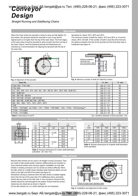
When the chain enters the sprocket, it tends to raise and fall slightly. For<br />
this reason, the sprocket should be mounted in such a way that its<br />
highest point is no higher than the top of the wear strips. The front edges<br />
of the wear strips should be bevelled to allow smooth and free running of<br />
the chain. Figure 3 and the following formula and dimensions are<br />
intended as a recommendation for aligning the sprocket with the top of<br />
the wear strip.<br />
Sprockets for chains 1873, 2873 and 3873:<br />
The minimum number of teeth for chains, 1873 and 3873, is 15 and for<br />
chains, 2873, 24 teeth. If the number of teeth is less than this minimum,<br />
the distance between the hub of the sprocket and the hold-down tabs is<br />
insufficient (see figure 4)<br />
P<br />
+ 6<br />
0<br />
+ 1<br />
0<br />
H<br />
+ 1<br />
0<br />
H<br />
Distance between<br />
sprocket hub<br />
and hold down tabs<br />
Hub dia.<br />
Pitch dia.<br />
Fig. 3- Alignment of the sprocket<br />
Chain No.<br />
FGM 1050 - FTM 1050<br />
FTM 1055<br />
512 - 802 - 805 - 812 - 815 - 820 - 821 - 881 - 881 M - 8811 - 8811 TAB - SLBP 821<br />
831 - XLBP 831<br />
880 - 880 TAB - 880 BO<br />
879 - 879 TAB - 879 BO - LBP 879 BO<br />
882 - 882 TAB - SLBP 882 TAB - LBP 883<br />
866 - 963 - 1864 - 1873 - 1874 - 2873 - 3873<br />
1108<br />
1700K - 1700TABK - AC1700K - 1701 - 1790K - 1790TABK - 1702 - 1716K - 1765 ZeroGap<br />
1710K - 1710TABK<br />
1713K - 1713TABK<br />
Table 2- dimensions H and P<br />
b<br />
d1<br />
t<br />
d1<br />
mm<br />
25<br />
30<br />
35<br />
40<br />
45<br />
50<br />
b<br />
mm<br />
nom.<br />
8<br />
8<br />
10<br />
12<br />
14<br />
14<br />
Rexnord idler wheels can be used in all straight running conveyors. They<br />
are made of high quality plastic material, selflubricating and resistant to<br />
most chemical solution and corrosive agents. Installation of most idler<br />
wheels in existing conveyors can be carried out without difficulty. Place<br />
the idler wheel on a bright drawn stainless steel shaft and attach one set<br />
collar to the right and left of the wheel (see figure 5)<br />
Smoothest running is achieved when the idler wheel is installed slightly<br />
lower than the top of the wear strip. For sideflexing chains, sprockets<br />
should also be used on the idler side. In new conveyors, Rexnord idler<br />
wheels should be used throughout the system. Ensure that the correct<br />
clearances are observed as shown in figure5.<br />
As the idler wheels run on a shaft, bearings are not necessary.<br />
toll.<br />
+ 0,036<br />
0<br />
+ 0,043<br />
0<br />
Keyway dimensions<br />
nom.<br />
28,3<br />
33,3<br />
38,3<br />
43,3<br />
48,8<br />
53,8<br />
t<br />
mm<br />
toll.<br />
60 18<br />
64,4<br />
Table 3- Keyway dimensions for metric shaft diameters<br />
(UNI 6604 - 69 / ISO 773)<br />
Idler wheels<br />
Fig. 4- Minimum number of teeth for TableTop <strong>Chains</strong><br />
Shaft of bright down stainless steel<br />
www.bergab.ru Берг АБ bergab@ya.ru Тел. 101 (495)-228-06-21, факс (495) 223-3071<br />
+ 0,2<br />
0<br />
1,2 - 1,6<br />
d1<br />
inch<br />
1 "<br />
1 1/4 "<br />
1 1/2 "<br />
1 3/4 "<br />
2 "<br />
Part. 612<br />
Fig. 5- Installation and alignment of idler wheel<br />
H - mm<br />
P - mm<br />
(Dp:2) + 3,5 26<br />
(Dp:2) + 3,4 26<br />
(Dp:2) + 3,2 40<br />
(Dp:2) + 2,4 40<br />
(Dp:2) + 3,6 40<br />
(Dp:2) + 2,8 40<br />
(Dp:2) + 4,8 40<br />
(Dp:2) + 11<br />
40<br />
(Dp:2) - 6,5<br />
26<br />
(Dp:2) - 12<br />
50<br />
(Dp:2) + 18<br />
50<br />
(Dp:2) + 16<br />
50<br />
Dp = primitive diameter of drive sprocket - mm.<br />
b<br />
inch<br />
min max<br />
0,250 0,252<br />
0,250 0,252<br />
0,375 0,377<br />
0,375 0,377<br />
0,500 0,502<br />
Table 4- Keyway dimensions for imperial shaft diameters<br />
(USA standard)<br />
+ 6<br />
P 0<br />
t<br />
inch<br />
min max<br />
1,114 1,124<br />
1,367 1,377<br />
1,669 1,679<br />
1,922 1,932<br />
2,223 2,233<br />
+ 1<br />
0<br />
H