General Trouble Shooting Instructions Electric Models 555L 555S
General Trouble Shooting Instructions Electric Models 555L 555S
General Trouble Shooting Instructions Electric Models 555L 555S

Create successful ePaper yourself
Turn your PDF publications into a flip-book with our unique Google optimized e-Paper software.
<strong>General</strong> <strong>Trouble</strong> <strong>Shooting</strong> <strong>Instructions</strong><br />
<strong>Electric</strong> <strong>Models</strong> <strong>555L</strong> <strong>555S</strong><br />
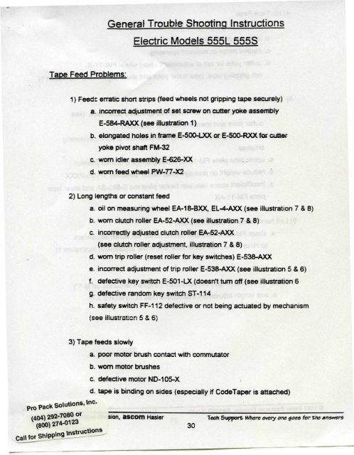
Tape Feed Problems:<br />
1 ) Feeds erratic short strips (feed wheels not gripping tape securely)<br />
a. incorrect adjustment of set screw on cutter yoke assembly<br />
E-584-RAXX (see illustration 1)<br />
b. elongated holes in frame E-500-LXX or E-500-RXXfor cutter<br />
yoke pivot shaft FM-32<br />
c. worn idler assembly E-626-XX<br />
d. worn feed wheel PW-77-X2<br />
2) Long lengths or constant feed<br />
a. oil on measuring wheel EA-18-BXX, EL-4-AXX (see illustration 7 & 8)<br />
b. worn dutch roller EA-52-AXX (see illustration 7 & 8)<br />
c. incorrectly adjusted clutch roller EA-52-AXX<br />
(see clutch roller adjustment, illustration 7 & 8)<br />
d. worn trip roller (reset roller for key switches) E-538-AXX<br />
e. incorrect adjustment of trip roller E-538-AXX (see illustration 5 & 6)<br />
f. defective key switch E-501-LX (doesn't turn off (see illustration 6<br />
g. defective random key switch ST-114<br />
h. safety switch FF-112 defective or not being actuated by mechanism<br />
(see illustration 5 & 6)<br />
3) Tape feeds slowly<br />
a. poor motor brush contact with commutator<br />
b. worn motor brushes<br />
c. defective motor ND-105-X<br />
pro Pack Solutions, Inc. ^ _<br />
d. tape is binding on sides (especially if CodeTaper is attached)<br />
^^ _<br />
(404) 292-7080 Of sjon ascom Hasler Tech Support Where every one goes for the answers<br />
(800)274-0123 3Q
4) No Tape Feed<br />
a. motor not operating ND-105-X<br />
b. solenoid not operating E-550<br />
c. neither motor or solenoid operating<br />
d. cutter yoke far out of adjustment - feed wheel PW-77-X<br />
not gripping tape, (see cutter yoke and shear adjustment, illustration 1)<br />
5) Tape Jams<br />
a. shear blade FM-20-BX doesn't lift up before tape feeds, (see<br />
cutter yoke and shear adjustment, illustration 1)<br />
b. lape is being pinched by pressure plate due to worn moistening<br />
brushes<br />
c. upper tape plate FM-12-EL missing or not in correct position<br />
d. reduce weight on pressure plate heater assembly TH-55-PXXX<br />
e. insufficient space between heater pivot rod E-580-SA and lower tape<br />
plate FM-11 -AX<br />
6) Left hand comer of tape folded over<br />
a. shear FM-20-BX too low. (check rocker set screw adjustment<br />
to raise shear, see cutter yoke and shear adjustment, illustration 1)<br />
7) Strips not correct length, but consistent (lengths inaccurate up to 1 M )<br />
a. see length adjustment instructions (see illustration 5 & 6)<br />
Pro Pack Solutions, Inc.<br />
(404) 292-7080 or<br />
(800)274-0123<br />
Call for Shipping <strong>Instructions</strong><br />
© 1993 Better Packages Division, ascom Hasier Tech Support Where every one goes for the answers<br />
31
<strong>Electric</strong>al Problems<br />
1) Machine doesn't operate but pilot light and heater work<br />
a. improperly adjusted safety switch FF-112 so that switch<br />
doesn't close when measuring wheel EA-18-BXX or EL-4-AXX<br />
returns terrest. (see safety switch adjustment, illustration 5 & 6)<br />
b. defective safety switch FF-112 or assembly (see illustration 5 & 6)<br />
2) Machine doesn't operate, pilot light doesn't light<br />
a. power cord not plugged in<br />
b. break in power cord PC-PG-1 AX<br />
c. main power switch defective ST-113<br />
3) Machine doesn't operate: pilot lights - heater doesn't work<br />
a. harness plug from key drum to machine not plugged in or<br />
connections are poor<br />
b. wire nuts E-634 and E-634A connecting motor ND-105-X<br />
and solenoid E-550 inside motor cover are not<br />
making good connection<br />
4) Motor doesn't operate<br />
a. poor connection at wire nuts E-634 and E-634A under<br />
motor cover<br />
b. worn motor brushes<br />
c. brushes not contacting commutator<br />
d. defective motor ND-105-X<br />
5) Solenoid doesn't operate<br />
a. poor connection at wire nuts E-634, E-634A under<br />
motor cover<br />
b. defective solenoid E-550-X<br />
Pro Pack Solutions, Inc.<br />
(404) 292-7080 or<br />
O Better Packages Division, ascom Master Tech Support ( 80 °) 274 " 0123<br />
32 ^all for Shipping <strong>Instructions</strong>
a. defective key switch E-5Q1-LX (see illustration 6)<br />
7) random switch doesn't operate<br />
a. defective random switch ST-114<br />
Pro Pack Solutions, Inc.<br />
(404) 292-7080 or<br />
(800)274-0123<br />
Call for Shipping <strong>Instructions</strong><br />
© 1993 Better Packages Division, ascom Hasler Tech Support Where every one goes for the answers<br />
33
Cutting Problems<br />
1) Shear Problems<br />
a. shear blades have accumulated asphalt or norv asphattic<br />
gum. Clean with suitable solvent and keep blade oiler fully<br />
oiled.<br />
b. Check stationary blade FM-21-X for correct lateral adjustment<br />
(see lateral blade adjustment illustration 2 & 3)<br />
c. blades dull FM-20-BX, FM-21-X (see illustration 1)<br />
d. Cutter spring E-585-C needs replacing<br />
e. Shear pivot holes cutter yoke E-584-RAX worn elongated<br />
f. Solenoid E-550 has to much up and down motion on mounting<br />
plate, (see solenoid adjustment, illustration 4)<br />
pack Solutions, inc.<br />
© Better Packages Division, ascom Hasler Tech Support Where every one goes for the answers<br />
34
Miscellaneous Problems<br />
1) Solenoid E-550 buzzes, (see solenoid adjustment, illustration 4)<br />
a. Solenoid mounting too tight, (not free to align itself, illustration 4)<br />
b. Solenoid mounting screws not evenly tightened,<br />
(plunger of solenoid not evenly seated, illustration 4)<br />
c. Rust in and around plunger of solenoid.<br />
d. Solenoid sponge pad E-599 worn or deteriorated.<br />
2) Tape roll jumps out when feeding.<br />
a. Core from previous roll of tape in machine.<br />
b. Bottom roller FM-59-X in basket missing or broken.<br />
© 1993 Better Packages Division, ascom Hasier Tech Support Where every one goes for the answers<br />
35
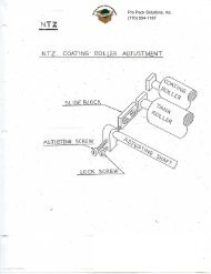
Cutting Edoe<br />
Stationary Blade<br />
Movable Blade & Blade<br />
Holder Assembly FM-20-BX<br />
Cuttina Edae Movable Blade<br />
Correct Blade Height<br />
1/32"<br />
When Feed Wheels<br />
Start to Grip<br />
Stationary Blade<br />
FM-21<br />
•<br />
Riaht Frame<br />
Cutter Yoke<br />
E-584-RAXX<br />
Set Screw FM-73<br />
To Raise Moveabie Blade - Turn Counter clockwise<br />
To Lower Moveabie Blade - Turn Clockwise<br />
Left Frame<br />
\nc.<br />
pack Solution^,'-<br />
View From Rear<br />
Movable Shear Blade Adjustment<br />
Illustration 1<br />
G Better Packages Division, ascom Hasler<br />
36<br />
Tech Support Where every one goes for the answers
Cutter Yoke and Movable Shear Blade Adjustment<br />
Model <strong>555L</strong> & <strong>555S</strong><br />
See Illustration 1<br />
The purpose of this adjustment is to insure that the movable shear blade FM-20-BX is<br />
raised out of the path of the tape before the feed wheels come together and grip the tape to<br />
feed it forward.<br />
Tools needed: 1. LN-23 Hex Screw Driver 3/32"<br />
2. Short piece of reinforced tape<br />
Unplug the machine from the power source. Remove bottle, brush tank and upper tape<br />
plate. Place a short strip of reinforced tape under the feed wheel. Reach into the opening in<br />
the front of the machine and lift the cutter yoke and movable shear assembly E-584-RAXX<br />
until the separable feed wheels are brought together and just grip the tape. At this point<br />
Increased resistance to lifting the cutter yoke assembly E-534-RAXX should be felt. Do this<br />
operation several times to Be sure to get the exact point at which the feed wheels start to grip<br />
the piece of tape. When this point is found, note the position of the lowest portion of the<br />
cutting edge of the movable shear blade FM-20-BX with respect to the stationary blade<br />
FM-21. If the adjustment is correct, there will be an opening for the tape approximately 1/32"<br />
high in the comer. See figure 1<br />
On the rear end of the cutter yoke assembly is a set screw which controls the height of<br />
the moving shear at the same time the feed wheels initially grip the tape. This set screw can<br />
be seen by looking through the large hole in the vertical tie plate in front of the basket section<br />
of the machine. If it as been found that the moving blade was too low, turn the set screw<br />
counterclockwise several turns and recheck the position. If the moving blade is too high, turn<br />
the set screw clockwise until the correct position is reached. After the adjustment has been<br />
made, the cutter yoke assembly should be lifted to be sure that after the feed wheels start to<br />
grip the tape it can raise still further against increased resistance.<br />
Try dispensing tape, If the tape is catching on the comer of the shear and jamming,<br />
(turning up the left hand corner of the tape, or the tape is slipping under the feed wheels), the<br />
adjustment was not correctly made.<br />
O 1993 Better Packages Division, ascom Hasler<br />
37<br />
Tech Support Where every one goes for the answers
—' _ BtetteOter<br />
Tipped Back<br />
Adjusting<br />
Screw<br />
1/3T<br />
SMfemiyBlMtoFM-21<br />
View from Front of Machine Looking Down on the Cutter Blades<br />
Illustration 2<br />
Location of Adjusting Screw<br />
View of Right Frame<br />
Illustration 3<br />
etter Packages Division, ascom Master<br />
38<br />
Tech Support Where every one goes for the answers
Lateral Adjustment of Stationary Blade<br />
<strong>Models</strong> <strong>555L</strong>. <strong>555S</strong><br />
See Illustration 2 & Illustration 3<br />
Tools Needed: 1 Phillips Screw Driver<br />
Unplug machine from power source. Face machine at the front. Tip back blade oiler to<br />
expose stationary blade FM-21. A spacing of approximately 1/32" should be visible between<br />
stationary and movable blades on the left hand side when the movable blade is down. The<br />
blades should be touching-onlhe right side. * ^<br />
If no spacing is visible or spacing is incorrect on the left, then you Must go to the<br />
adjusting screw on the right side of the frame. This adjusting screw is in the form of a phillips<br />
head screw and a washer, located halfway down the chain cover on the side frame. Loosen<br />
the screw just enough to allow movement up and down. Move up for more space, move down<br />
for less space.<br />
NOTE:<br />
Some difficult-cutting reinforced tapes may<br />
require the maximum spacing on the left side,<br />
(approximately 3/64").<br />
Pro Pack Solutions, Inc.<br />
(404) 292-7080 or<br />
(800)274-0123<br />
Call for Shipping <strong>Instructions</strong><br />
© 1993 Better Packages Division, ascom Hasler Tech Support. Where every one goes for the answers<br />
39
Sotonoid Mounting Screw*<br />
Illustration 4<br />
Pro Pack Solutions, Inc.<br />
(404) 292-7080 or<br />
(800)274-0123<br />
Call for Shipping <strong>Instructions</strong><br />
O Bener Packages Division, ascom Hasier<br />
40<br />
Tech Support Where every one goes for the answers
Solenoid- Adjustment<br />
<strong>Models</strong> <strong>555L</strong>. <strong>555S</strong><br />
See Illustration 4<br />
Tools Needed:<br />
3/8" Open End Wrench<br />
5/16" Nut Driver<br />
When the solenoid buzzes it is an indication that the cutter yoke linkage and the<br />
solenoid are not in correct alignment. More often than not, the misalignment can be traced to<br />
uneven tightness of the four mounting screws of the solenoid.<br />
Either tighten or loosen both screws on one half of the machine, then operate the<br />
machine if buzzing doesn't stop repeat to other side of machine. Operate the machine several<br />
times to see if the buzzing as been cured.<br />
If this doesn't cure the problem and you are certain that the solenoid is in proper<br />
alignment, remove the solenoid and shelf assembly from the machine and look for dirt under<br />
the armature of the solenoid. The solenoid should not be tighten down tight. It should be loose<br />
enough so that it can slide from side to side on it's mounting screws. If it is too loose and there<br />
is too much up and down motion on the mounting screws, the cutting may be sluggish.<br />
Pro Pack Solutions, inc.<br />
(404) 292-7080 or<br />
© 1993 Better Packages Division, ascom Hasler Tech Support Where every one goes for the answers<br />
41
10<br />
O Better Packages Division, ascom Master<br />
42<br />
Tech Support Where every one goes for the answers
Safety Switch Adjustment<br />
Model <strong>555L</strong><br />
See Illustration 5<br />
Tools needed: Screw Driver<br />
5/16" Open End Wrench<br />
Needle Nose Pliers<br />
Unoluo machine from power source. Remove key drum assembly. To the right of the<br />
measuring wheel is the safety switch assembly EA-570-BX At the base of this assembly is the<br />
safety switch spring E-565-B. This is where the adjustment will be made.<br />
With the screw driver, turn the reset screw all the way up. Now with the needle nose<br />
pliers bend the flat spring at the right-hand side at the curved portion to shift the reset screw<br />
and allow it to move freely in the slot. Check adjustment by pressing down the switch pin from<br />
the top. Revolve measuring wheel manually to make sure the switch shuts off when the<br />
bumper suction cup comes within 1/4" of the bumper plate. If it doesn't, readjust the screw and<br />
spring until it resets at the proper point.<br />
With screw driver and 5/16" open end wrench, tighten to secure the screw in position.<br />
pro Pack Solutions, inc.<br />
or<br />
© 1993 Better Packages Division, ascom Hasler Tech Support Where every one goes for the answers<br />
43
Lerrqtfr Adjustment<br />
Model <strong>555L</strong><br />
See Illustration 5<br />
Tools needed: LN-25 hex screw driver<br />
Unolua machine from power source. Remove Access Hole Cover E-575. With the<br />
LN-25 hex screw driver, loosen the Cap Screw FF-90 that holds the Bumper Cup Arm to the<br />
Measuring Wheel.<br />
Hold Bumper Cup Arm against the bumper plate and move Cap Screw and Measuring<br />
Wheel in clockwise direction to shorten, counter clockwise to lengthen. Re tighten Cap Screw<br />
to secure.<br />
Pro Pack Solutions, Inc.<br />
(404) 292-7080 or<br />
(800)274-0123<br />
Call for Shipping <strong>Instructions</strong><br />
© Better Packages Division, ascom Hasler Tech Support Where every one qoes for the answers<br />
44
Length Adjustment<br />
Model <strong>555S</strong><br />
See Illustration 6<br />
Tools needed: LN-26 Hex Screw Driver<br />
Unolua machine from the power source. Remove Access Hole Cover E-575 and Button<br />
Hole Plug E-695. With the LN-26 Hex Screw Driver, go through the hole left by the removal of<br />
the hole plug, and loosen the EA-5 Cap Screw. Move the Radius Plate in a counter clockwise<br />
direction to shorten lengths, and in a clockwise direction to lengthen. Re tighten Cap Screw to<br />
secure.<br />
© 1993 Better Packages Division, ascom Hasler Tech Support Where every one goes for the answers<br />
45
CD<br />
•52<br />
•ss ,0or<br />
© Better Packages Division, ascom Raster<br />
46<br />
Tech Support Where every one goes for the answers
Trip Roller Adjustment<br />
Model <strong>555L</strong> - See Illustration 5<br />
Model <strong>555S</strong> - See Illustration 6<br />
Tools Needed: 5/16" Long Arm Allen Wrench—<br />
LN-964 Hex Screw Driver<br />
Unplug machine from power source, remove Access Hole Cover E-575. This will enable<br />
you to get at the trip roller easily.<br />
To vary the contact pressure of the trip roller against the reset button of the switches,<br />
the trip arm assembly EA-39-AXX carrying the trip roller assembly must be adjusted inward or<br />
outward as the case may be.<br />
To decrease the contact pressure of the trip roller on the switches, you will have to first<br />
back off on the set screw EA-45 a few turns, using the long arm alien wrench 5/64. Next the<br />
two Cap Screws EA-42 must be loosened with 9/64 Hex Screw Driver LN-42 and the trip arm<br />
assembly will slide back from the switches. The correct adjustment for the trip roller is to hit<br />
the switches just hard enough to reset the key switches, but not so hard as to cause the trip<br />
roller to hang up on any of the key switches.<br />
To increase the contact pressure on the trip roller against the key switches, you must<br />
first loosen the two Cap Screws EA-42 then turn the Set Screw EA-45 in a few turns, re tighten<br />
the Cap Screws, then revolve manually to check trip roller pressure on the switches.<br />
To check the trip roller pressure against the reset button of the Key Switches, manually<br />
revolve the measuring wheel so that the roller passes the first key switch. Now press the<br />
button down and hold it. Gently bring back the measuring wheel until it comes in contact with<br />
the switch you are pressing. It should hold back and not release the roller until your finger is<br />
removed from the button. Each individual switch should be checked in this manner. If only a<br />
few switches are not right, the key switch E-501-L may be individually adjusted by either<br />
tightening or loosening the knurled nut on top. If the majority are not correct, the trip arm must<br />
be readjusted, and the others brought into alignment by their individual adjustment.<br />
As a final test press down all the key switches, then manually revolve the measuring<br />
wheel slowly, making sure all the key switches are being reset. Be sure on the return trip the<br />
trip roller doesn't hit the switches with enough pressure to hang up. Be sure this pressure is<br />
the same on each key switch around the key drum.<br />
Pa* Solutions, me.<br />
© 1993 Better Packages Division, ascom Hasier Tech Support Where every one qoes for the answers<br />
47
Clutch Connecting Rod<br />
EA-SZ<br />
Clutch Roller<br />
EA-62-AXXX<br />
1/32" Clearance<br />
Solenoid Energized<br />
Measuring Wheel EA18BXX<br />
Illustration 7<br />
Model 555 & 556<br />
Clutch COfYMCtm<br />
RodEA-57<br />
Clutch Rotter<br />
EA-52-AXXX<br />
1/32* Ctoerwic* «_*_<br />
Sotanoid not EMIUIZMO<br />
pro Pack Solutions, \nc.<br />
(404) 292-7080 or<br />
(800)274-0123<br />
Illustration 8<br />
Model <strong>555L</strong><br />
Tech Support Where every one goes for the answers<br />
48
•<br />
Clutch Roller Adjustment<br />
<strong>Models</strong> <strong>555L</strong> & <strong>555S</strong><br />
See Illustration 7 & Illustration 8<br />
Tools Needed: 1 Special Adjustment Driver<br />
Unoluo machine from power source. Remove Key Drum Assembly. The clutch roller is<br />
located to the upper right hand side of the measuring wheel. When the machine is operated,<br />
this roller drives the measuring wheel to reset the actuated key switch.<br />
In the reset position, solenoid unenergized, the clutch roller should be adjusted for<br />
approximately 1/32" clearance between it and the measuring wheel. The adjustment is<br />
changed by using your special adjusting driver on the rectangular top of the clutch connecting<br />
rod. Turning the connecting rod clockwise lowers the adjustment, counter clockwise raises the<br />
adjustment. This spacing is important, because the measuring wheel should start moving at<br />
the same time the tape begins to feed in order to get the correct tape lengths.<br />
After the adjustment has been made, reach into the front of the machine after removing<br />
the tank and raise the rocker and shear assembly to the top position. The clutch roller should<br />
then be contacting the measuring wheel with enough pressure to drive the measuring wheel.<br />
NOTE: Keep fingers off flange of measuring wheel, clutch<br />
roller and gear assembly. Any oil from fingers or<br />
another source will prevent proper operation of the<br />
measuring mechanism. It is also recommended that<br />
when installing a new clutch roller that you clean it<br />
first with contact cleaner.<br />
Pro Pack Solutions, inc.<br />
(404) 292-7080 or<br />
^ (800) 274-0123<br />
ascom Master<br />
49<br />
Tech Support Where every one goes for the answers
Measuring Wheef Tension Spring Setting<br />
Model <strong>555L</strong> See Illustration 5<br />
Model <strong>555S</strong> See Illustration 6<br />
Tools required: Tin-Arc Retaining Ringr Pliers:<br />
Unpluc machine from power source. Remove Key Drum Assembly. The tension on the<br />
clock spring is what returns the measuring wheel back to its starting position as soon as the<br />
feed cycle is completed and the clutch roller is released from contact with the measuring<br />
wheel. This tension is not critical, but must be enough to return the measuring wheel quickly,<br />
But not enough to cause so much resistance to the measuring wheel that slippage is<br />
encountered when the dutch roller is turning it during the feeding cycle.<br />
The spring is carried in a metal cup mounted on the pivot shaft for the measuring<br />
wheel. The cup and spring can be rotated with respect to the measuring wheel after the<br />
retaining ring is removed. To rotate the cup it must be pulled out slightly so that it disengages<br />
from the two pins mounted on the measuring wheel hub. After the proper tension is achieved,<br />
the cup must be returned to the pins to retain proper spring tension.<br />
The following is the tension applied to each model at the factory:<br />
Model <strong>555L</strong><br />
With the bumper cup resting against the bumper plate, 1/2 turn counter<br />
clockwise. See Illustration 5<br />
Model <strong>555S</strong><br />
With the bumper cup resting against the bumper plate, 1/2 turn clockwise.<br />
See Illustration 6<br />
© Better Packages Division, ascom Hasler Tech Support- Where every one qoes for the answers<br />
50
o<br />
CO<br />
CO<br />
ft<br />
C/l<br />
Pilot<br />
115 VAC<br />
o<br />
O<br />
Power Switch<br />
*<br />
en<br />
to<br />
Solenoid<br />
o<br />
8 Ut<br />
Top<br />
Heater<br />
Q55/B<br />
Random Length<br />
Key Normally Open<br />
-| gt<br />
2nd<br />
3rd<br />
Key Switches<br />
Reset Type<br />
Schematic Wiring Diagram of <strong>555L</strong> and <strong>555S</strong><br />
10th<br />
11th<br />
to<br />
U><br />
§
Grounded Hug<br />
Grounding 8Mp<<br />
Omni To OraufMfl<br />
************<br />
en<br />
ro<br />
Wlrt Nute (2)<br />
I»f1 Frvrm<br />
Wiring Diagram of <strong>555L</strong> and <strong>555S</strong>