ST7 FLASH STICK User Manual - propox
ST7 FLASH STICK User Manual - propox
ST7 FLASH STICK User Manual - propox

You also want an ePaper? Increase the reach of your titles
YUMPU automatically turns print PDFs into web optimized ePapers that Google loves.
<strong>ST7</strong> <strong>FLASH</strong> <strong>STICK</strong><br />
<strong>User</strong> <strong>Manual</strong><br />
Release 1.1<br />
September 2002<br />
Ref: DOC-<strong>STICK</strong>-PP
INSTRUCTIONS FOR USE—WARNING<br />
This product is conform to the 89/336/EEC Directive. It complies with the ITE EN55022 standard for<br />
EMC emissions and generic 50082-1 (1992 edition) immunity standards.<br />
This product is an FCC Class-A apparatus. In a residential environment, it may cause<br />
radioelectrical disturbances.<br />
In addition, this programming board is not contained in an outer casing; consequently, it cannot be<br />
immune against electrostatic discharges (ESD). It should therefore be handled only in static safe<br />
working areas. Please refer to Appendix A: <strong>User</strong> and Work Environment Precautions on page 20 for<br />
relevant safety information<br />
USE IN LIFE SUPPORT DEVICES OR SYSTEMS MUST BE EXPRESSLY AUTHORIZED.<br />
STMicroelectronics PRODUCTS ARE NOT AUTHORIZED FOR USE AS CRITICAL COMPONENTS IN<br />
LIFE SUPPORT DEVICES OR SYSTEMS WITHOUT THE EXPRESS WRITTEN APPROVAL OF<br />
STMicroelectronics. As used herein:<br />
1. Life support devices or systems are those<br />
which (a) are intended for surgical implant into<br />
the body, or (b) support or sustain life, and whose<br />
failure to perform, when properly used in<br />
accordance with instructions for use provided<br />
with the product, can be reasonably expected to<br />
result in significant injury to the user.<br />
2. A critical component is any component of a life<br />
support device or system whose failure to<br />
perform can reasonably be expected to cause the<br />
failure of the life support device or system, or to<br />
affect its safety or effectiveness.
Table of Contents<br />
Chapter 1: Introduction . . . . . . . . . . . . . . . . . . . . . . . . . . . . . . . . . . . . . . . . . . 4<br />
1.1 In-Circuit Communication protocol (ICC) ...................................................... 5<br />
1.2 Your host PC and application board requirements ....................................... 5<br />
1.3 ICC connector signals ................................................................................... 6<br />
1.4 About this manual... ...................................................................................... 7<br />
Chapter 2: Getting Started . . . . . . . . . . . . . . . . . . . . . . . . . . . . . . . . . . . . . . . . 8<br />
2.1 Delivery checklist .......................................................................................... 8<br />
2.2 Installing the STVP7 software ....................................................................... 8<br />
2.3 Setting up the hardware ................................................................................ 9<br />
2.4 Launching STVP7 for the first time ............................................................. 11<br />
Chapter 3: Programming With STVP7 . . . . . . . . . . . . . . . . . . . . . . . . . . . . . . 16<br />
Appendix A: <strong>User</strong> and Work Environment Precautions . . . . . . . . . . . . . . . . . 20<br />
Appendix B: Troubleshooting . . . . . . . . . . . . . . . . . . . . . . . . . . . . . . . . . . . . . . 22<br />
B.1 Test pins ..................................................................................................... 22<br />
B.2 Error messages .......................................................................................... 23<br />
B.3 “Problem on supply voltages” ..................................................................... 23<br />
B.4 “Cannot communicate with the device” ....................................................... 24<br />
Appendix C: Glossary . . . . . . . . . . . . . . . . . . . . . . . . . . . . . . . . . . . . . . . . . . . . 26<br />
Appendix D: Schematics . . . . . . . . . . . . . . . . . . . . . . . . . . . . . . . . . . . . . . . . . . 28<br />
Product Support . . . . . . . . . . . . . . . . . . . . . . . . . . . . . . . . . . . . . . . . . . . . . . . . . 30<br />
Getting prepared before you call............................................................................... 30<br />
Contact list ................................................................................................................ 30<br />
Software updates ...................................................................................................... 31<br />
Index . . . . . . . . . . . . . . . . . . . . . . . . . . . . . . . . . . . . . . . . . . . . . . . . . . . . . . . . . . . 32<br />
3/34
<strong>STICK</strong> <strong>User</strong> <strong>Manual</strong><br />
1 - Introduction<br />
1 INTRODUCTION<br />
The ST In-circuit Communication Kit (<strong>STICK</strong>) is an ideal introduction to the easyto-use<br />
world of <strong>ST7</strong> Flash microcontrollers. It is a complete kit for programming the<br />
Flash <strong>ST7</strong> microcontroller of the following series:<br />
• <strong>ST7</strong>Lite series<br />
• <strong>ST7</strong>226x series<br />
• <strong>ST7</strong>232x series<br />
• <strong>ST7</strong>252x series<br />
• <strong>ST7</strong>256x series<br />
The <strong>STICK</strong> acts as a communications interface between your PC and the <strong>ST7</strong><br />
Flash microcontroller soldered on your application board. It can program <strong>ST7</strong><br />
Flash devices powered with any voltage within their datasheet-specified range.<br />
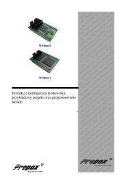
<strong>STICK</strong> is delivered ready-to-use, and it includes <strong>ST7</strong> Visual Programmer software<br />
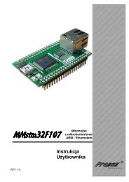
(STVP7), the <strong>ST7</strong> Flash <strong>STICK</strong> Interface board, a power supply and all necessary<br />
cables.<br />
Figure 1: <strong>STICK</strong> interface board<br />
4/34
1 - Introduction <strong>STICK</strong> <strong>User</strong> <strong>Manual</strong><br />
1.1 In-Circuit Communication protocol (ICC)<br />
An In-Circuit Communication (ICC) protocol has been developed by<br />
STMicroelectronics to minimize the hardware needed on your application board<br />
and the number of signals used by the <strong>ST7</strong> to communicate with the outside world.<br />
To handle the ICC protocol, an ICC monitor is embedded in all <strong>ST7</strong> Flash<br />
microcontroller types. For more detailed information about the ICC Protocol, refer<br />
to the <strong>ST7</strong> ICC Protocol Reference <strong>Manual</strong>, available in PDF format on the MCUon-CD<br />
CD-ROM.<br />
The three different applications described below use the ICC protocol:<br />
• ICP: In-Circuit Programming is an <strong>ST7</strong> <strong>FLASH</strong> programming method using the<br />
ICC communication protocol. ICP is used to update the entire contents of the<br />
<strong>FLASH</strong> memory (including option bytes). For more details, see “<strong>FLASH</strong><br />
Programming” reference manual.<br />
• ICT: In-Circuit Testing is a flexible method of performing production test<br />
routines that can be easily modified and extended without affecting the content<br />
of the <strong>FLASH</strong> program memory.<br />
• ICD: In-Circuit Debugging is the ability to debug a <strong>FLASH</strong> device using the ICC<br />
protocol. This ability is used in low-cost <strong>ST7</strong> emulators such as SofTec’s<br />
InDART emulator.<br />
1.2 Your host PC and application board requirements<br />
Both hardware and software components of the <strong>STICK</strong> have been designed to<br />
work with PCs meeting the following requirements:<br />
• One of the following operating systems: Microsoft ® Windows ® 95, 98, 2000,<br />
Millennium, NT ® or XP.<br />
• Intel ® Pentium (or compatible) processor with minimum speed of 133 MHz.<br />
• Minimum RAM of 32 MB (64 MB recommended).<br />
• 50 MB of free hard disk space to install all of the <strong>ST7</strong> tools.<br />
Note:<br />
Windows ® 2000, NT ® and XP users must have administrator privileges to install the required<br />
software.<br />
You must design your application with an HE10 connector on your application<br />
board to carry the ICC signals described in the next section.<br />
5/34
<strong>STICK</strong> <strong>User</strong> <strong>Manual</strong><br />
1 - Introduction<br />
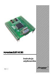
1.3 ICC connector signals<br />
Depending on the type of <strong>ST7</strong> Flash microcontroller you are using, ICP needs a<br />
minimum of 4 or 5 signals and up to 6 or 7 signals to be connected to the ICC<br />
connector on the <strong>STICK</strong> Interface board.<br />
• The following 4 or 5 signals are mandatory on the ICC connector:<br />
- GND: Ground.<br />
GND 1 2 ICCDATA<br />
GND 3 4 ICCCLK<br />
GND 5 6 ICCRESET<br />
VDD_appli 7 8 ICCSEL_VPP<br />
ICCOSC 9 10 GND<br />
Figure 2: ICC connector map<br />
- ICCDATA: During ICP activity, the application board must not drive (source<br />
or sink) more than 1 mA of current.<br />
- ICCCLK: During ICP activity, the application board must not drive (source<br />
or sink) more than 1 mA of current.<br />
- ICCRESET: During ICP activity, the application board must not drive<br />
(source or sink) more than 5 mA of current.<br />
- ICCSEL_VPP: The application pull-down resistor must not be lower than<br />
10 kOhm. (Note that the ICCSEL_VPP signal doesn’t exist on the<br />
<strong>ST7</strong>2FLITE0x).<br />
• The following 2 signals are optional:<br />
- VDD_appli: Needed if the W1 jumper is in the VDD position (see Section<br />
2.3 on page 9).<br />
- ICCOSC: Safe clock. Only necessary if ICP_OPT_Disable programming<br />
mode (see Section 2.4 on page 11) is used and if your <strong>ST7</strong> Flash<br />
application clock is not a square wave from 0 V to V DD (if, for example, you<br />
use the internal RC oscillator of the <strong>ST7</strong> Flash Microcontroller, or have a<br />
resonator or an RC on the OSC1/OSC2 pins). In this case ICCOSC safe<br />
clock must be connected to the OSC1 pin of the <strong>ST7</strong> Flash microcontroller<br />
in your application.<br />
For more information, see the datasheet of the <strong>ST7</strong> Flash microcontroller.<br />
6/34
1 - Introduction <strong>STICK</strong> <strong>User</strong> <strong>Manual</strong><br />
1.4 About this manual...<br />
The following conventions are used in this manual:<br />
• Bold text highlights key terms and phrases, and is used when referring to<br />
names of dialog boxes and windows, as well as tabs and entry fields within<br />
windows or dialog boxes.<br />
• Bold italic text denotes menu commands (or sequence of commands),<br />
options, buttons or checkboxes which you must click with your mouse in order<br />
to perform an action.<br />
• The > symbol is used in a sequence of commands to mean “then”. For<br />
example, to open an application in Windows, we would write: “Click<br />
Start>Programs><strong>ST7</strong> Tool Chain>....”.<br />
• Courier or typewriter font designates file names, programming<br />
commands, path names and any text or commands you must type.<br />
• Italicized type is used for value substitution. Italic type indicates categories of<br />
items for which you must substitute the appropriate values, such as arguments,<br />
or hypothetical filenames. For example, if the text was demonstrating a<br />
hypothetical command line to compile and generate debugging information for<br />
any file, it might appear as:<br />
cxst7 +mods +debug file.c<br />
• Items enclosed in [brackets] are optional. For example, the line:<br />
[options]<br />
means that zero or more options may be specified because options appears in<br />
brackets. Conversely, the line:<br />
options<br />
means that one or more options must be specified because options is not<br />
enclosed by brackets.<br />
As another example, the line:<br />
file1.[o|st7]<br />
means that one file with the extension .o or .st7 may be specified, and the<br />
line:<br />
file1 [file2...]<br />
means that additional files may be specified.<br />
• Blue italicized text indicates a cross-reference—you can link directly to the<br />
reference by clicking on it while viewing with Acrobat Reader.<br />
7/34
<strong>STICK</strong> <strong>User</strong> <strong>Manual</strong><br />
2 - Getting Started<br />
2 GETTING STARTED<br />
2.1 Delivery checklist<br />
Check that your <strong>STICK</strong> box contains the following:<br />
• One <strong>STICK</strong> interface board (marked “<strong>ST7</strong> <strong>FLASH</strong> <strong>STICK</strong>-LPT”).<br />
• One AC/DC power supply adaptor.<br />
• One PC parallel port cable.<br />
• One 10-pin HE10 type ribbon cable for ICC connectors.<br />
• A “Welcome to the world of <strong>ST7</strong> <strong>FLASH</strong>” letter.<br />
• One “Microcontroller Development Tools” CD-ROM containing:<br />
- This user manual.<br />
- <strong>ST7</strong> Visual Programmer (STVP7) software and other <strong>ST7</strong> development<br />
tools software.<br />
• A Product and Tool Selection Guide.<br />
• The <strong>ST7</strong> ASM Quick Reference Guide.<br />
• The “MCU on CD” CD-ROM which contains datasheets, application notes and<br />
other documentation for ST Microcontrollers.<br />
2.2 Installing the STVP7 software<br />
Your <strong>STICK</strong> comes with a CD-ROM containing several <strong>ST7</strong> software tools. These<br />
tools are compatible with Windows ® 95, 98, Me, 2000, XP and Windows ® NT ®<br />
operating systems.<br />
Note:<br />
Windows ® 2000, NT ® and XP users must have administrator privileges to install the STVP7.<br />
To install and setup the <strong>ST7</strong> software tools, follow these steps:<br />
1 Close all other open applications on your Windows desktop.<br />
2 Insert the Microcontroller Development Tools CD-ROM into your CD-ROM<br />
drive. The CD-ROM’s autorun feature will open up a welcome screen on your<br />
PC. If the autorun feature does not work, use Windows ® Explorer to browse to<br />
the CD-ROM’ s root folder, and double-click on Welcome.exe.<br />
3 Use your mouse to place the cursor over the <strong>ST7</strong> option. Choose <strong>ST7</strong><br />
Programming Software from the list that appears.<br />
4 The install wizard will be launched. Follow the instructions that appear on the<br />
screen.<br />
8/34
2 - Getting Started <strong>STICK</strong> <strong>User</strong> <strong>Manual</strong><br />
5 Reboot your PC as prompted before connecting the hardware (see Setting up<br />
the hardware on page 9) and launching STVP7 for the first time.<br />
2.3 Setting up the hardware<br />
1 Connect the <strong>STICK</strong> interface board to the LPT1 port of your host PC with the<br />
supplied parallel cable.<br />
Note:<br />
Be sure to use the PC parallel port cable provided with your <strong>STICK</strong>—using a longer<br />
PC parallel port cable may cause malfunctions.<br />
Connect the cable directly between the host PC and the <strong>STICK</strong> interface board—the insertion<br />
of additional cables or switch boxes between the host PC and the <strong>STICK</strong> interface board may<br />
cause malfunctions.<br />
If a dongle (a hardware key required by some software packages) is already connected to the<br />
PC’s parallel port, it should not interfere with <strong>STICK</strong> interface board. However, if a malfunction<br />
of the board should occur, please remove the dongle and restart the above sequence.<br />
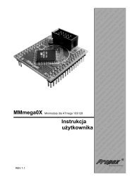
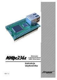
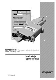
2 Configure the <strong>STICK</strong> by setting W1 jumper according to your application.<br />
Power supply<br />
connector<br />
W1 jumper<br />
ICC connector<br />
TP1 test points<br />
Figure 3: <strong>STICK</strong> interface board component layout<br />
The W1 jumper must be set to one of the three following positions:<br />
- V DD : The power supply voltage of the <strong>STICK</strong>’s ICC buffer follows the<br />
application V DD . This position allows you to work with any V DD value<br />
allowed in the <strong>ST7</strong> datasheet. When the jumper is in this position, you must<br />
9/34
<strong>STICK</strong> <strong>User</strong> <strong>Manual</strong><br />
2 - Getting Started<br />
connect the application V DD to pin 7 of the ICC connector. <strong>STICK</strong> uses the<br />
application V DD as voltage reference signal, only a 10 kOhm pull-down<br />
resistor is connected on this V DD line.<br />
- 5V: The power supply voltage of the <strong>STICK</strong>’s ICC buffer is 5 V. You don’t<br />
need to connect the application V DD to pin 7 of the ICC connector, but your<br />
application must be powered by 5 V +/- 5%.<br />
- 3.3 V: The power supply voltage of the <strong>STICK</strong>’s ICC buffer is 3.3 V. You<br />
don’t need to connect the application V DD to pin 7 of the ICC connector, but<br />
your application must be powered by 3.3 V +/- 5%.<br />
3 Power on the <strong>STICK</strong> using the AC/DC power supply adaptor provided. Ensure<br />
that the AC/DC power supply adaptor is adapted to the mains voltage and outlet<br />
type used in your country.<br />
10/34
2 - Getting Started <strong>STICK</strong> <strong>User</strong> <strong>Manual</strong><br />
2.4 Launching STVP7 for the first time<br />
To set up STVP7 for the <strong>STICK</strong>, follow these instructions:<br />
1 From your host PC, select Start>Programs><strong>ST7</strong> Tool Chain>Development<br />
Tools><strong>ST7</strong> Visual Programmer to start STVP7.<br />
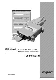
2 The first time STVP7 is started the Configuration window shown in Figure 4 is<br />
opened.<br />
Note:<br />
This configuration dialog box can be opened again using Configure menu, click Configure<br />
<strong>ST7</strong> Visual Programmer (or press the<br />
button).<br />
Figure 4: Configuration dialog box<br />
3 From Hardware list, select <strong>STICK</strong>.<br />
4 From Port list select PC parallel port LPT1.<br />
5 From the Programming mode list, you must select one of the three modes.<br />
Depending on Programming mode selected, a specific <strong>ST7</strong> Flash Device list<br />
will be displayed.<br />
Selecting the correct programming mode is critical in order to program your<br />
microcontroller. To correctly choose the Programming mode, you have to:<br />
- Find the option byte description in your <strong>ST7</strong> Flash microcontroller’s<br />
datasheet.<br />
- Check whether the <strong>ST7</strong> is ex-factory or not. Ex-factory devices are brand<br />
new devices with factory default options programmed.<br />
11/34
<strong>STICK</strong> <strong>User</strong> <strong>Manual</strong><br />
2 - Getting Started<br />
Then use Table 1 to determine the programming mode:<br />
Question<br />
1 Does your <strong>ST7</strong> Flash microcontroller<br />
have an option byte?<br />
2 In your <strong>ST7</strong> Flash microcontroller’s<br />
option byte description, can<br />
you select the OSCTYPE?<br />
3 Is your <strong>ST7</strong> Flash microcontroller<br />
ex-factory?<br />
4 Have you already programmed<br />
the <strong>ST7</strong> Flash option bytes with<br />
the OSCTYPE that matches your<br />
application hardware?<br />
Response<br />
No<br />
Yes<br />
No<br />
Yes<br />
No<br />
Yes<br />
No<br />
Yes<br />
Programming<br />
mode or next<br />
action<br />
ICP<br />
go to next question<br />
ICP<br />
go to next question<br />
go to next question<br />
ICP OPT Enable<br />
ICP OPT Disable<br />
ICP OPT Enable<br />
Table 1: Determining the programming mode<br />
To better explain the differences between the programming modes, here is a<br />
brief description of each:<br />
- ICP: This programming mode is for <strong>ST7</strong> Flash devices without OSCTYPE<br />
choice possibility in the option byte. Currently, for <strong>ST7</strong> devices supported by<br />
<strong>STICK</strong>, only <strong>ST7</strong>2HUB is in this category. For all other <strong>ST7</strong> devices you<br />
have to select one of the other programming modes.<br />
- ICP OPT Disable: This programming mode is a safe mode. It must be used<br />
when ICP OPT Enable configuration does not work. This can be the case if<br />
your application clock circuitry doesn’t match the previously programmed<br />
OSCTYPE option byte selection. In this programming mode, an external<br />
source with a square wave signal from 0 V to V DD must be applied. This<br />
clock can be provided either by your application, or by the ICC connector<br />
pin 9 (ICCOSC safe clock).<br />
- ICP OPT Enable: This programming mode has to be selected if the<br />
<strong>ST7</strong> Flash is ex-factory, or if your application clock circuitry matches the<br />
previously programmed OSCTYPE option byte selection. In this<br />
programming mode, the ICCOSC safe clock from the ICC connector pin 9<br />
is not needed.<br />
12/34
2 - Getting Started <strong>STICK</strong> <strong>User</strong> <strong>Manual</strong><br />
Caution:<br />
6 From Device list, select the <strong>ST7</strong> Flash microcontroller to be programmed.<br />
Depending on the <strong>ST7</strong> Flash microcontroller you choose, you be able to specify<br />
additional protection settings—refer to STVP7’s online help.<br />
If you do not find the name of your <strong>ST7</strong> Flash microcontroller in this Device list, it is either<br />
because you chose the wrong Programming mode, or your STVP7 version doesn’t support<br />
this <strong>ST7</strong> Flash microcontroller yet. In this latter case you have to download the latest STVP7<br />
release from ST’s website at http://mcu.st.com.<br />
7 Click OK to save your changes and close the Configuration window. The main<br />
STVP7 application window is opened, as shown in Figure 5.<br />
Figure 5: STVP7 main application window<br />
8 Power on your application hardware.<br />
Caution:<br />
9 Connect the HE10 type ribbon cable to the <strong>STICK</strong> interface board ICC<br />
connector on one end and to your application board ICC connector on the other<br />
end.<br />
This connection should be done after STVP7 is launched to avoid to apply unwanted voltage<br />
value on ICC pins as STVP7 initializes the PC parallel port.<br />
13/34
<strong>STICK</strong> <strong>User</strong> <strong>Manual</strong><br />
2 - Getting Started<br />
10 Now you can go directly to Programming With STVP7 on page 16, to learn how<br />
to:<br />
- Load, Edit and Save executable and/or data files in the Intel ® HEX or<br />
Motorola ® S19 formats, generated by the Assembler/Linker or C Compiler<br />
for <strong>ST7</strong> microcontrollers.<br />
- Erase and Program <strong>ST7</strong> Flash microcontroller memory.<br />
- View and Verify the microcontroller memory contents.<br />
- Create a Project file to automatize all tasks needed to configure STVP7<br />
and to program <strong>ST7</strong> microcontrollers.<br />
14/34
2 - Getting Started <strong>STICK</strong> <strong>User</strong> <strong>Manual</strong><br />
15/34
<strong>STICK</strong> <strong>User</strong> <strong>Manual</strong><br />
3 - Programming With STVP7<br />
3 PROGRAMMING WITH STVP7<br />
In this chapter, we explain how to perform a typical programming session.<br />
Note that this is not the only way to program an <strong>ST7</strong> microcontroller using STVP7;<br />
for more information on how to use the STVP7, click the Help command in the<br />
main menu bar.<br />
1 Make sure you have already:<br />
- installed STVP7 (as described in Section 2.2 on page 8),<br />
- set up and configured the <strong>STICK</strong> interface board W1 jumper (as described<br />
in Section 2.3 on page 9),<br />
- set up STVP7 for the first time (as described in Section 2.4 on page 11).<br />
2 If your microcontroller has <strong>ST7</strong> Flash memory—either XFlash (EEPROM<br />
technology, byte-erasable) or HDFlash (<strong>FLASH</strong> technology, sector-erasable)—<br />
each byte must be erased before being reprogrammed.<br />
- XFlash memory: Anything present in this memory zone is automatically<br />
erased when you program or reprogram this type of memory. Because of<br />
this, the Erase command is neither necessary nor available with XFlash<br />
memory. For the same reason a Blank-Check command is not available for<br />
XFlash memory.<br />
- HDFlash memory: You cannot erase single bytes—only sectors. Before<br />
programming byte(s) or sector(s) you must have erased the appropriate<br />
sector(s). To erase, in the STVP7 main window, click on Erase>Active<br />
sector(s) (or press the button). You can use Blank-Check command to<br />
verify that the correct sectors are erased.<br />
3 In the STVP7 main window, use the tab menu to select the memory area that<br />
you wish to program (for example, PROGRAM MEMORY, DATA MEMORY or<br />
OPTION BYTE).<br />
16/34
3 - Programming With STVP7 <strong>STICK</strong> <strong>User</strong> <strong>Manual</strong><br />
4 Click on Open in the File menu (or press the button). The Open dialog box<br />
appears.<br />
Figure 6: Open dialog box<br />
5 Browse to the directory that contains the file you want to program, and then<br />
select it.<br />
6 Click on Open. When the file is loaded, the Output area displays the file<br />
checksum and device checksum.<br />
7 To open other memory area data files, repeat steps [3] to [6], selecting the<br />
appropriate memory area tab for each data file.<br />
8 Edit the option byte value. In the STVP7 main window, use the tab menu to<br />
select option byte then click on the name or the description you want to<br />
change to get the description pop-up menu and make your choice. For more<br />
information on the option byte see your <strong>ST7</strong> Flash microcontroller datasheet.<br />
9 Execute the programming session: in the STVP7 main window, click on<br />
Program>All tabs (on active sectors if any) (or press the button on the<br />
right side of the toolbar). Note: The programming session does all the<br />
programming checks.<br />
10 You can check the <strong>ST7</strong> content but this is not mandatory as this is done during<br />
the programming session. To do this, in the STVP7 main window, click on<br />
Verify>All tabs (on active sectors if any) (or press the button on the right<br />
side of the toolbar).<br />
17/34
<strong>STICK</strong> <strong>User</strong> <strong>Manual</strong><br />
3 - Programming With STVP7<br />
Note:<br />
In the STVP7 main window, the Program>Current tab allows you to program only the<br />
selected tab (for example, program memory or option byte).<br />
11 When you have finished programming, disconnect the HE10 type ribbon cable<br />
from the ICC connector on your application board in order to run your<br />
application.<br />
18/34
3 - Programming With STVP7 <strong>STICK</strong> <strong>User</strong> <strong>Manual</strong><br />
19/34
<strong>STICK</strong> <strong>User</strong> <strong>Manual</strong><br />
Appendix A: <strong>User</strong> and Work Environment Precautions<br />
APPENDIX A: USER AND WORK ENVIRONMENT PRECAUTIONS<br />
The following precautions are recommended when using the programming board:<br />
• Any tester, equipment, or tool used at any production step or for any<br />
manipulation of semiconductor devices should have its shield connected to<br />
ground.<br />
• Your programming board should be placed on a conductive table top, made of<br />
steel or clean aluminum or covered by an antistatic surface (superficial<br />
resistivity equal to or higher than 0.5 MΩ/cm 2 ), grounded through a ground<br />
cable (conductive cable from protected equipment to ground isolated through a<br />
1MΩ resistor placed in series).<br />
All manipulation of finished goods should be made at such a grounded<br />
worktable.<br />
• The worktable should be free of all non-antistatic plastic objects.<br />
• An antistatic floor covering grounded through a conductive ground cable (with<br />
serial resistor between 0.9 and 1.5 MΩ) should be used.<br />
• It is recommended that you wear an antistatic wrist or ankle strap, connected to<br />
the antistatic floor covering or to the grounded equipment.<br />
• If no antistatic wrist or ankle strap is worn, before each manipulation of the<br />
powered-on programming board, you should touch the surface of the grounded<br />
worktable.<br />
• It is recommended that antistatic gloves or finger coats be worn.<br />
• It is recommended that nylon clothing be avoided while performing any<br />
manipulation of parts.<br />
20/34
Appendix A: <strong>User</strong> and Work Environment Precautions<br />
<strong>STICK</strong> <strong>User</strong> <strong>Manual</strong><br />
21/34
<strong>STICK</strong> <strong>User</strong> <strong>Manual</strong><br />
Appendix B: Troubleshooting<br />
APPENDIX B: TROUBLESHOOTING<br />
This appendix covers some of the problems that may occur, and how to solve<br />
them.<br />
B.1 Test pins<br />
The <strong>STICK</strong> board is equipped with test pins located at TP1 (see board layout in<br />
Figure 3 on page 9). If you have problems with programming, these pins can help<br />
you pinpoint anomalies in the ICC communication by testing or checking the ICC<br />
signals.<br />
Pin Signal Description<br />
1 GND This pin is marked with a white dot.<br />
2 Power The external power supply value can be checked<br />
here. It is an unregulated 12 V DC power supply.<br />
Its value should be in the range 13.5 V to 23 V<br />
depending on the current load.<br />
3 VCC The V CC is regulated at 5 V +/- 5%.<br />
4 VCC_a This is the operational amplifier output that follows<br />
the voltage value selected by the W1 jumper. It<br />
should be equal to:<br />
• your application V DD voltage value if W1 is in<br />
the V DD position,<br />
• 5 V if W1 is in the 5 V position,<br />
• 3.3 V if W1 is in the 3.3 V position.<br />
5 ICCSEL_VPP This signal may be at 0 V, 5 V or 12 V . This test<br />
point is used during factory test. You do not have<br />
to check it.<br />
Table 1 Test pins<br />
22/34
Appendix B: Troubleshooting<br />
<strong>STICK</strong> <strong>User</strong> <strong>Manual</strong><br />
B.2 Error messages<br />
The following sections explain the cause of some of the commoner error<br />
messages.<br />
B.2.1<br />
“PC parallel port cable not connected”<br />
Most communication failures between the host PC running STVP7 and the <strong>STICK</strong><br />
interface board stem from problems in the parallel port connection. To prevent<br />
communication problems, when setting up your parallel port connection, ensure<br />
that:<br />
• You use the parallel cable provided with your <strong>STICK</strong>—using a longer parallel<br />
cable may cause malfunctions.<br />
• Connect the cable directly between the host PC and <strong>STICK</strong> interface board—<br />
the insertion of additional cables or switch boxes between the host PC and the<br />
interface board may cause malfunctions.<br />
• You remove any parallel port dongles.<br />
• Ensure LPT1 address is in the range 03BC-03BF or 0378-037F or 0278-027F.<br />
• Ensure that “printer port LPT1” is not disabled in your PC. For example, in the<br />
IBM ® ThinkPad, you can select “infrared printing (LPT) port on”.<br />
B.3 “Problem on supply voltages”<br />
When you have supply voltage problems the green LED will not come on. To find<br />
the cause of the problem:<br />
• Check that the AC/DC power supply adaptor is firmly connected to both the<br />
main power supply and to the <strong>STICK</strong> interface board. To check that the main<br />
power supply is on, disconnect ICC cable and measure the voltage at test pin 2<br />
at location TP1 (see Test pins on page 22). This pin should have unregulated<br />
DC value in the range 18 V to 21 V.<br />
Note:<br />
Ground is on TP1 pin 1 (white dot mark).<br />
• Check that the W1 jumper is set on one of the three positions, see Section 2.2<br />
on page 8. If it is set on the “VDD” position, check that the ICC cable is<br />
connected properly and that your application’s VDD is connected to ICC<br />
connector pin 7. Your application VDD must be in the range 2.4 V to 5 V. On<br />
test pin 4 at location TP1 (see Test pins on page 22), you must have the same<br />
voltage value that you selected with the W1 jumper.<br />
• Check that there is 5 V on test pin 3 at location TP1 (see Test pins on page 22).<br />
23/34
<strong>STICK</strong> <strong>User</strong> <strong>Manual</strong><br />
Appendix B: Troubleshooting<br />
If you have made all of these checks and you still get the “Problem on supply<br />
voltages” message, contact your ST distributor or sales office (see Product<br />
Support on page 30) in order to have your <strong>STICK</strong> repaired.<br />
B.4 “Cannot communicate with the device”<br />
Check that:<br />
• The ICC cable is well connected.<br />
• You have selected the right <strong>ST7</strong> device.<br />
• The ICC signals are clear and within the following ranges:<br />
- ICCDATA: This application signal must not drive more than 1 mA.<br />
- ICCCLK: This application must not drive more than 1 mA.<br />
- ICCRESET: This application must not drive more than 5 mA.<br />
- ICCSEL_VPP: The pull-down resistor must not be lower than 10 kOhm.<br />
• You have selected the right programming mode in the main menu<br />
Configure window > programming mode list, see Section 2.3 on page 9.<br />
Remember that:<br />
- If you use ICP OPT Enable mode, check that your application clock<br />
circuitry does match the CLOCK SOURCE and OSCTYPE options already<br />
programmed in <strong>ST7</strong> Flash microcontroller option byte. For devices out of<br />
factory you have to check these values in datasheet. If you don’t know<br />
these values you have to select ICP OPT Disable.<br />
- ICP OPT Disable mode, ensure that external source clock is a square<br />
wave signal from 0 V to VDD. If not, you have to connect ICCOSC safe<br />
clock (ICC connector pin 9) to the OSC1 pin of the <strong>ST7</strong>Flash<br />
microcontroller in your application<br />
24/34
Appendix B: Troubleshooting<br />
<strong>STICK</strong> <strong>User</strong> <strong>Manual</strong><br />
25/34
<strong>STICK</strong> <strong>User</strong> <strong>Manual</strong><br />
Appendix C: Glossary<br />
APPENDIX C: GLOSSARY<br />
ex-factory<br />
This appendix gives a brief definition of acronyms and names used in this manual.<br />
Ex-factory, when applied to microcontrollers, means that they are direct from the<br />
factory and retain their default settings. This is particularly pertinent important<br />
when applied to option bytes.<br />
HDFlash<br />
High density <strong>FLASH</strong> memory is based on <strong>FLASH</strong> technology. The HDFlash is<br />
used for microcontrollers with 4K up to 60Kbytes of <strong>FLASH</strong> memory. The HDFlash<br />
is programmed byte by byte but erased by sector.<br />
ICC protocol<br />
ICC monitor<br />
ICP<br />
ICT<br />
ICD<br />
In-Circuit Communication protocol is a way of exchanging data between an<br />
<strong>ST7</strong> Flash microcontroller and an external system (i.e. PC) using minimum<br />
hardware and <strong>ST7</strong> I/Os in the user application. In the <strong>ST7</strong> Flash microcontrollers,<br />
this protocol is handled by the ICC monitor.<br />
Software that handles the ICC protocol, embedded in a reserved memory area of<br />
the <strong>ST7</strong> Flash microcontroller. At RESET, using specific signal sequence, the <strong>ST7</strong><br />
jumps to this ICC monitor which allows it to download programs in RAM and to<br />
execute them. This feature is used to implement the ICP functionality.<br />
In-Circuit Programming. This is programming the <strong>ST7</strong> <strong>FLASH</strong> memory while<br />
<strong>ST7</strong> Flash microcontroller is plugged into the application board.<br />
In-Circuit Testing. This is testing <strong>ST7</strong> Flash micro and/or your application through<br />
the <strong>ST7</strong> Flash microcontroller while it is plugged into the application board.<br />
In-Circuit Debugging. This is debugging your application while the <strong>ST7</strong> Flash<br />
microcontroller is plugged into the application board.<br />
<strong>ST7</strong> Flash microcontroller<br />
<strong>ST7</strong> Flash microcontroller with electrically erasable memory that can be either<br />
XFlash memory or HDFlash.<br />
26/34
Appendix C: Glossary<br />
<strong>STICK</strong> <strong>User</strong> <strong>Manual</strong><br />
<strong>STICK</strong><br />
STVP7<br />
XFlash<br />
ST In-circuit Communication Kit.<br />
<strong>ST7</strong> Visual Programmer. This software programs runs on a PC. It has a graphical<br />
Windows ® interface and supports different types of <strong>ST7</strong> programming hardware<br />
(<strong>STICK</strong>, EPBs, DVPs).<br />
Extended <strong>FLASH</strong> memory is based on EEPROM technology. XFlash provides<br />
extended features such as byte re-programming (by means of byte erasing) and<br />
data EEPROM capability. The XFlash microcontrollers are available between 1K to<br />
16 Kbytes.<br />
27/34
28/34<br />
A<br />
VCC<br />
A<br />
C31<br />
B<br />
enVPP<br />
C12<br />
GND<br />
Power<br />
4.7nF<br />
C33<br />
C34<br />
GND<br />
+<br />
U9A<br />
R11<br />
RS8 10K<br />
1MF<br />
Power<br />
35V<br />
GND 2 3 7 8<br />
10K<br />
R7 100<br />
5 6<br />
VDD_APPLI 2 1<br />
W1<br />
3 4<br />
74VHC126_a<br />
GND<br />
5V 1 2<br />
1 2<br />
VCC_a<br />
VCC<br />
40mA max<br />
3.3V 3 4<br />
8 7<br />
U7B<br />
5 6<br />
1 2<br />
R8<br />
(5V) 6 5<br />
13<br />
R4<br />
+<br />
4 3<br />
MW2X3C<br />
3 1 2<br />
1 2 R_VCC_a R13 33K<br />
1 2 1<br />
14 -<br />
1<br />
L272D 180-1W<br />
22K<br />
MCDT - Development Tools - GRENOBLE<br />
RS3 10K<br />
1.2W<br />
C22 C21<br />
GND<br />
C23<br />
+<br />
Title<br />
B<br />
4.7MF<br />
16V<br />
C<br />
D<br />
D<br />
<strong>ST7</strong>ICC - Parallel Port<br />
mcu.st.com<br />
Power<br />
GND<br />
180pF 180pF 180pF 180pF 180pF 180pF 180pF<br />
1<br />
LD1<br />
2 VCC<br />
GND<br />
VCC_a<br />
GND 2<br />
1<br />
RS5<br />
3<br />
4 ICCSEL_VPP<br />
10K<br />
R9 10K<br />
5<br />
LED_Green<br />
1 2<br />
R1<br />
VCC<br />
MW1X5C<br />
1.5K<br />
4 J1<br />
4<br />
1 NSTROBE<br />
RS6 33<br />
14 NAUTF<br />
7 8 Rnautf<br />
U6<br />
D1 pcDOUT<br />
D0<br />
pcACK pcDOUT<br />
2 DATA0<br />
5 6 D0<br />
2<br />
NERROR<br />
Rnerror<br />
Rnautf 1A1 1Y1<br />
18<br />
pcRESET pcACK<br />
15<br />
3 4<br />
4<br />
DATA1<br />
D1<br />
D2<br />
1A2 1Y2<br />
16<br />
pcCLKen pcRESET<br />
3<br />
1 2<br />
C29<br />
6<br />
14<br />
INIT<br />
R_VCC_a<br />
PEND<br />
D3 pcRW pcCLKen<br />
16<br />
100pF<br />
1A3 1Y3<br />
8<br />
DATA2<br />
D2<br />
D5<br />
enSEL<br />
D4 pcPULSES<br />
pcRW<br />
4<br />
RS4<br />
1A4 1Y4<br />
12<br />
7 8<br />
11<br />
NSELIN<br />
EN_OSC GND<br />
D6<br />
2A1 2Y1<br />
9<br />
enVPP<br />
pcPULSES<br />
17<br />
5 6<br />
13<br />
DATA3<br />
D3<br />
pcDATAIN 2A2 2Y2<br />
7<br />
5<br />
3 4<br />
15<br />
Rbusy<br />
18 GND<br />
D4 pcPULSES<br />
pcSTATUS<br />
Rnerror<br />
6 DATA4<br />
33 2 2A3 2Y3<br />
5<br />
1<br />
17<br />
2A4 2Y4<br />
3<br />
19 GND<br />
DATA5<br />
GND 1<br />
7<br />
RS1 33<br />
1G<br />
19<br />
ICCSEL_VPP<br />
GND<br />
D5<br />
2G<br />
ICCSEL_VPP0<br />
20<br />
7 8<br />
8 DATA6<br />
5 6 D6<br />
74VHCT244<br />
21 GND<br />
3 4 Rbusy<br />
pcSTATUS<br />
DATA7<br />
pcDATAIN<br />
pcSTATUS<br />
9<br />
1 2<br />
GND<br />
pcDATAIN<br />
22<br />
3<br />
10 ACK<br />
VDD_APPLI<br />
GND<br />
EN_OSC VDD_APPLI<br />
23<br />
BUSY<br />
EN_OSC<br />
11<br />
RS2<br />
3<br />
24 GND<br />
12 PEND<br />
100K<br />
25 GND<br />
13 SLCT<br />
V1<br />
Power<br />
C10 C6 C15 C16 C18 C24<br />
SUBD25C_F_COUDE GND 180pF 180pF 180pF 180pF 180pF 180pF<br />
GND<br />
U10<br />
13<br />
3<br />
GND<br />
X0 X<br />
VCC_a<br />
14<br />
R14<br />
X1<br />
15<br />
R15<br />
X2<br />
U2<br />
VCC<br />
VCC<br />
12<br />
47<br />
C5<br />
X3<br />
1<br />
1.2K<br />
J2 +<br />
4.7nF<br />
Power<br />
X4<br />
GND<br />
CG<br />
2<br />
GND<br />
5<br />
X5<br />
1<br />
3<br />
B CG<br />
5<br />
2<br />
L78L05-SO8<br />
X6<br />
2<br />
1<br />
4<br />
C14<br />
X7<br />
3<br />
Z1<br />
PSG CG<br />
6<br />
8<br />
I<br />
O<br />
1<br />
2 T3<br />
C13<br />
CB<br />
4<br />
6<br />
U7A<br />
GND<br />
enSEL<br />
INH<br />
11<br />
A<br />
11<br />
R16 12K<br />
MMBT2907<br />
2 JACK_2.5mm<br />
BNX002<br />
C3 C2 + C1 U1<br />
C4 + C8<br />
10<br />
2<br />
B<br />
5 1 2<br />
9<br />
C<br />
12<br />
4.7MF<br />
16V<br />
74HC4051<br />
L272D<br />
1 2<br />
P6KE24A<br />
1<br />
2<br />
1<br />
2<br />
1<br />
2<br />
2.2nF<br />
1 2<br />
1<br />
2<br />
1<br />
3<br />
5<br />
7<br />
2<br />
4<br />
6<br />
8<br />
100nF<br />
C36<br />
1<br />
2<br />
1 2<br />
C38<br />
1<br />
2<br />
1 2<br />
1<br />
2<br />
1 2<br />
1 2<br />
100nF<br />
C28<br />
1<br />
2<br />
1<br />
2<br />
C27<br />
1<br />
2<br />
1 2<br />
C26<br />
1<br />
2<br />
1<br />
2<br />
4<br />
6<br />
GND<br />
C25<br />
1<br />
2<br />
2.2nF<br />
1<br />
2<br />
100nF<br />
1<br />
2<br />
2<br />
4<br />
6<br />
8<br />
1<br />
3<br />
5<br />
7<br />
220MF<br />
2<br />
3<br />
6<br />
7<br />
C<br />
TP1<br />
1<br />
2<br />
1<br />
2<br />
1<br />
2<br />
VEE<br />
1<br />
2<br />
1<br />
2<br />
100nF<br />
100nF<br />
1<br />
1<br />
2<br />
4 6<br />
-<br />
+<br />
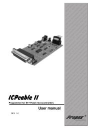
MB372C: <strong>ST7</strong>-<strong>FLASH</strong> <strong>STICK</strong>-LPT<br />
Size Document Number Rev<br />
A4<br />
PC Parallel Port Link<br />
C<br />
Date: Tuesday, June 04, 2002<br />
Sheet 1 of 2<br />
1<br />
2<br />
1<br />
2<br />
1<br />
2<br />
E<br />
E<br />
100nF<br />
1<br />
2<br />
1<br />
3<br />
1<br />
2<br />
APPENDIX D: SCHEMATICS<br />
<strong>STICK</strong> <strong>User</strong> <strong>Manual</strong> Appendix D: Schematics
A<br />
A<br />
B<br />
B<br />
C<br />
C<br />
D<br />
D<br />
E<br />
E<br />
Appendix D: Schematics<br />
<strong>STICK</strong> <strong>User</strong> <strong>Manual</strong><br />
VCC<br />
Power<br />
R10<br />
1 2<br />
10<br />
pcACK<br />
pcDOUT<br />
U9C<br />
9 8<br />
ICCRESET<br />
R5<br />
5.6K<br />
pcCLKen<br />
74VHC126_a<br />
pcCLKen<br />
4 4<br />
pcRW<br />
U9B<br />
CLKINicc<br />
U4A<br />
R3<br />
1 2<br />
VCC_a<br />
4.7K<br />
MBT2907 or SO2907 SOT23<br />
74VHC14_a<br />
U4C<br />
U4B<br />
U9D<br />
VCC_a<br />
11<br />
12<br />
D1<br />
GND<br />
BAR42<br />
Schottky<br />
RS7-3<br />
5 6<br />
ICCCLK<br />
VDD_APPLI<br />
33<br />
VDD_APPLI<br />
74VHC14_a<br />
74VHC14_a<br />
74VHC126_a<br />
C35<br />
180pF<br />
3 Power<br />
3<br />
GND 2 3<br />
GND<br />
U3A 74VHC125_a<br />
ICC connector<br />
ICCDATA<br />
ICCCLK<br />
GND<br />
ICCRESET<br />
ICCSEL_VPP VDD_APPLI<br />
ICCOSC<br />
10<br />
GND<br />
JP1<br />
HEADER 5x2/SM<br />
GND<br />
pcCLKen<br />
VCC_a<br />
tie_CLK_low<br />
pcDATAIN<br />
VCC_a<br />
MBT2907 or SO2907 SOT23<br />
U4E<br />
74VHC125_a R6<br />
Q<br />
5 6<br />
11 10 9 8 1 2<br />
74VHC74_a<br />
D2<br />
U3B 74VHC125_a<br />
100<br />
BAR42<br />
U4F<br />
2 VCC_a<br />
2<br />
C11 74VHC14_a<br />
VCC_a<br />
Schottky<br />
pcACK<br />
V5<br />
13 12<br />
pcPULSES<br />
33pF<br />
U5A<br />
RS7-4<br />
GND<br />
74VHC14_a<br />
pcDOUT<br />
7 8 ICCDATA<br />
D Q<br />
12 11<br />
U3D 74VHC125_a<br />
33<br />
CLK<br />
VCC_a<br />
GND<br />
pcRW<br />
12<br />
D<br />
VCC<br />
VCC_a<br />
VCC_a<br />
33<br />
33<br />
1 1<br />
C32<br />
MCDT - Development Tools - GRENOBLE<br />
100nF<br />
Title<br />
MB372C: <strong>ST7</strong>-<strong>FLASH</strong> <strong>STICK</strong>-LPT<br />
Size Document Number Rev<br />
A3<br />
C<br />
ICC Link GND<br />
Tuesday, June 04, 2002 Date: Sheet of 2 2<br />
2<br />
4<br />
6<br />
8<br />
1<br />
3<br />
5<br />
7<br />
9<br />
2<br />
1<br />
V3<br />
T2<br />
MMBT2907<br />
C39<br />
1<br />
100nF<br />
6<br />
5<br />
2<br />
2<br />
3<br />
2<br />
1<br />
3<br />
1<br />
13<br />
V4<br />
V2<br />
U4D<br />
74VHC14_a<br />
RS7-1<br />
RS7-2<br />
74VHC74_a<br />
1 2<br />
3 4<br />
8<br />
9<br />
4<br />
C20<br />
1<br />
100nF<br />
2<br />
3<br />
2<br />
1<br />
12<br />
11<br />
U8B<br />
74VHC74_a<br />
V6<br />
2<br />
3<br />
5<br />
6<br />
2<br />
1<br />
1<br />
PR<br />
4<br />
Q<br />
C37<br />
180pF<br />
9<br />
8<br />
2<br />
CL<br />
1<br />
13<br />
10<br />
D<br />
CLK<br />
Q<br />
CL<br />
PR<br />
C7<br />
1<br />
C19<br />
100nF<br />
2<br />
1<br />
100nF<br />
2<br />
1<br />
2<br />
1<br />
pcACK<br />
pcDOUT<br />
10K<br />
pcRW<br />
T1<br />
MMBT2907<br />
C17<br />
22pF<br />
2<br />
2<br />
3<br />
1<br />
5 6<br />
74VHC126_a<br />
R2<br />
1 2<br />
3.3K<br />
U3C<br />
10<br />
C9<br />
1<br />
100nF<br />
4<br />
3<br />
2<br />
13<br />
2<br />
1<br />
1<br />
4<br />
pcPULSES<br />
pcPULSES<br />
pcRESET<br />
pcRESET<br />
ICCSEL_VPP<br />
ICCSEL_VPP0<br />
pcDATAIN<br />
pcDATAIN<br />
pcSTATUS<br />
pcSTATUS<br />
U8A<br />
74VHC74_a<br />
2<br />
3<br />
5<br />
6<br />
1<br />
4<br />
D<br />
CLK<br />
Q<br />
PR<br />
Q<br />
R12<br />
5.6K<br />
2<br />
1<br />
CL<br />
U5B<br />
11<br />
9<br />
8<br />
13<br />
10<br />
Q<br />
PR<br />
CLK<br />
Q<br />
CL<br />
2<br />
1<br />
EN_OSC<br />
C30<br />
1<br />
100nF<br />
2<br />
29/34
<strong>STICK</strong> <strong>User</strong> <strong>Manual</strong><br />
Product Support<br />
PRODUCT SUPPORT<br />
If you experience any problems with this product or if you need spare parts or<br />
repair, contact the distributor or ST sales office where you purchased the product.<br />
Getting prepared before you call<br />
Collect the following information about the product before contacting ST or your<br />
distributor:<br />
Contact list<br />
1 Name of the company where you purchased the programmer kit.<br />
2 Date of purchase.<br />
3 Order Code: Refer to the side of your programmer kit box. The order code will<br />
depend on the region for which it was ordered (i.e. the UK, Continental Europe<br />
or the USA).<br />
4 Serial Number: The serial number is located on a label on the programming<br />
board.<br />
5 Target Device: The sales type of the <strong>ST7</strong> microcontroller you are using in your<br />
development.<br />
Note:<br />
For American and Canadian customers seeking technical support the US/Canada is split<br />
in 3 territories. According to your area, contact the following sales office and ask to be<br />
transferred to an 8-bit microcontroller Field Applications Engineer (FAE).<br />
Canada and East Coast<br />
STMicroelectronics<br />
Lexington Corporate Center<br />
10 Maguire Road, Building 1, 3rd floor<br />
Lexington, MA 02421<br />
Phone: 781-402-2650<br />
Mid West<br />
STMicroelectronics<br />
1300 East Woodfield Road, Suite 410<br />
Schaumburg, IL 60173<br />
Phone: 847-585-3000<br />
30/34
Product Support<br />
<strong>STICK</strong> <strong>User</strong> <strong>Manual</strong><br />
West coast<br />
STMicroelectronics, Inc.<br />
28202 Cabot Road<br />
Suite 650<br />
Laguna Niguel, CA<br />
Phone: (949) 347-0717<br />
Europe<br />
France (33-1) 47407575<br />
Germany (49-89) 460060<br />
U.K. (44-1628) 890800<br />
Asia/Pacific Region<br />
Japan (81-3) 3280-4120<br />
Hong-Kong (852) 2861 5700<br />
Sydney (61-2) 9580 3811<br />
Taipei (886-2) 2378-8088<br />
Software updates<br />
You can get software updates from the ST Internet web site http://mcu.st.com.<br />
For information on firmware and hardware revisions, call your distributor or ST<br />
using the contact list given above.<br />
31/34
Index<br />
application<br />
voltage selection ..................................... 9<br />
board schematics .......................................... 28<br />
CD-ROM ......................................................... 8<br />
circuitry.......................................................... 28<br />
definitions...................................................... 26<br />
delivery checklist............................................. 8<br />
EMC compliancy<br />
requirements for.................................... 20<br />
error messages ............................................. 23<br />
finished goods<br />
manipulation of...................................... 20<br />
safety requirements .............................. 20<br />
glossary......................................................... 26<br />
hardware<br />
setting up ................................................ 9<br />
supplied................................................... 8<br />
ICC<br />
A<br />
B<br />
C<br />
D<br />
E<br />
F<br />
G<br />
H<br />
I<br />
connector pinout ..................................... 6<br />
definition of protocol ..............................26<br />
signal description.....................................6<br />
ICD (In-Circuit Debugging) ..............................5<br />
ICP (In-Circuit Programming) ..........................5<br />
ICT (In-Circuit Testing) ....................................5<br />
In Circuit Programming (ICP)<br />
programming in ICP mode.....................16<br />
M<br />
memory programming<br />
HDFlash.................................................16<br />
XFlash ...................................................16<br />
parallel connection<br />
restrictions/requirements .........................9<br />
programming board<br />
setting up .................................................9<br />
programming mode<br />
selecting ................................................11<br />
programming modes<br />
descriptions ...........................................12<br />
how to correctly determine ....................12<br />
ICP.........................................................12<br />
ICP OPT Disable ...................................12<br />
ICP OPT Enable ....................................12<br />
importance of.........................................11<br />
setting ....................................................11<br />
safety requirements .......................................20<br />
schemas ........................................................28<br />
setting up the <strong>STICK</strong> .......................................9<br />
software<br />
installing...................................................8<br />
updates..................................................31<br />
<strong>ST7</strong> Visual Programmer (STVP7)<br />
installing...................................................8<br />
typical programming session .................16<br />
support<br />
contact numbers for...............................30<br />
for programming board ..........................30<br />
information required...............................30<br />
P<br />
S<br />
32/34
Index<br />
terminology ................................................... 26<br />
test pins......................................................... 22<br />
T<br />
setting with W1 jumper ............................9<br />
W<br />
working environment recommendations........20<br />
V<br />
voltage<br />
33/34
3<br />
4<br />
Information furnished is believed to be accurate and reliable. However, STMicroelectronics assumes no responsibility for the<br />
consequences of use of such information nor for any infringement of patents or other rights of third parties which may result from its use.<br />
No license is granted by implication or otherwise under any patent or patent rights of STMicroelectronics. Specifications mentioned in this<br />
publication are subject to change without notice. This publication supersedes and replaces all information previously supplied.<br />
STMicroelectronics products are not authorized for use as critical components in life support devices or systems without the express written<br />
approval of STMicroelectronics.<br />
The ST logo is a registered trademark of STMicroelectronics.<br />
Intel ® is a U.S. registered trademark of Intel Corporation.<br />
Microsoft ® , Windows ® and Windows NT ® are U.S. registered trademarks of Microsoft Corporation.<br />
©2002 STMicroelectronics - All Rights Reserved.<br />
Purchase of I 2 C Components by STMicroelectronics conveys a license under the Philips I 2 C Patent. Rights to use these components in an<br />
I 2 C system is granted provided that the system conforms to the I 2 C Standard Specification as defined by Philips.<br />
STMicroelectronics Group of Companies<br />
Australia - Brazil - China - Finland - France - Germany - Hong Kong - India - Italy - Japan - Malaysia - Malta - Morocco - Singapore - Spain<br />
Sweden - Switzerland - United Kingdom - U.S.A.<br />
http://www.st.com