MR-J4 Servomotors and Amplifiers
MR-J4 Servomotors and Amplifiers
MR-J4 Servomotors and Amplifiers

Create successful ePaper yourself
Turn your PDF publications into a flip-book with our unique Google optimized e-Paper software.
• SERVOMOTORS AND AMPLIFIERS<br />
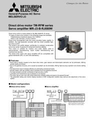
<strong>MR</strong>-<strong>J4</strong>-A (General Purpose Interface) Specifications<br />
Servo Amplifier Model <strong>MR</strong>-<strong>J4</strong>- 10A 20A 40A 60A 70A 100A 200A 350A 500A 700A<br />
Stocked Item S S S S S S S S S S<br />
Output<br />
Rated Voltage<br />
3-phase 170 VAC<br />
Rated Current (A) 1.1 1.5 2.8 3.2 5.8 6.0 11.0 17.0 28.0 37.0<br />
Voltage/Frequency (*1, *2) 3-phase or 1-phase 200 VAC to 240 VAC, 50/60 Hz 3-phase 200 VAC to 240 VAC, 50/60 Hz<br />
Main Circuit<br />
Power<br />
Rated Current (A) 0.9 1.5 2.6 3.2 (*8) 3.8 5.0 10.5 16.0 21.7 28.9<br />
Supply Permissible Voltage Fluctuation 3-phase or 1-phase 170 VAC to 264 VAC 3-phase 170 VAC to 264 VAC<br />
Permissible Frequency Fluctuation ±5% maximum<br />
Voltage/Frequency<br />
1-phase 200 VAC to 240 VAC, 50/60 Hz<br />
Control Rated Current (A) 0.2 0.3<br />
Circuit<br />
Power<br />
Permissible Voltage Fluctuation 1-phase 170 VAC to 264 VAC<br />
Supply Permissible Frequency Fluctuation ±5% maximum<br />
Power Consumption (W) 30 45<br />
Interface Power Supply<br />
24 VDC ±10% (required current capacity: 0.5 A (including CN8 connector signal))<br />
Load-Side Encoder Interface (*8)<br />
Mitsubishi high-speed serial communication<br />
Tolerable Regenerative Power of the Built-in<br />
Regenerative Resistor (*2, *3) (W)<br />
- 10 10 10 20 20 100 100 130 170<br />
Control Method<br />
Sine-wave PWM control/current control method<br />
Dynamic Brake Built-in (*4)<br />
Overcurrent shut-off, regenerative overvoltage shut-off, overload shut-off (electronic thermal), servo motor overheat protection,<br />
Protective Functions<br />
encoder error protection, regenerative error protection, undervoltage protection, instantaneous power failure protection, overspeed<br />
protection, error excessive protection, magnetic pole detection protection, linear servo control fault protection<br />
Maximum Input Pulse Frequency 4 Mpps (when using differential receiver), 200 kpps (when using open-collector)<br />
Positioning Feedback Pulse Encoder resolution: 22 bits<br />
Position<br />
Comm<strong>and</strong> Pulse Multiplying Factor Electronic gear A/B multiple, A: 1 to 16777216, B: 1 to 16777216, 1/10 < A/B < 4000<br />
Control<br />
Mode Positioning Complete Width Setting 0 pulse to ±65535 pulses (comm<strong>and</strong> pulse unit)<br />
Error Excessive<br />
±3 rotations<br />
Torque Limit<br />
Set by parameters or external analog input (0 V DC to +10 V DC/maximum torque)<br />
Speed Control Range Analog speed comm<strong>and</strong> 1:2000, internal speed comm<strong>and</strong> 1:5000<br />
Speed Analog Speed Comm<strong>and</strong> Input 0 V DC to ±10 V DC/rated speed (Speed at 10 V is changeable with [Pr. PC12].)<br />
Control<br />
±0.01% maximum (load fluctuation 0% to 100%), 0% (power fluctuation: ±10%)<br />
Mode<br />
Speed Fluctuation Rate<br />
±0.2% maximum (ambient temperature: 25 °C ± 10 °C) only when using analog speed comm<strong>and</strong><br />
Torque Limit<br />
Set by parameters or external analog input (0 V DC to +10 V DC/maximum torque)<br />
Torque Analog Torque Comm<strong>and</strong> Input 0 V DC to ±8 V DC/maximum torque (input impedance: 10 kΩ to 12 kΩ)<br />
Control<br />
Mode Speed Limit<br />
Set by parameters or external analog input (0 V DC to ± 10 V DC/rated speed)<br />
Fully Closed Loop Control<br />
Available in the future<br />
Safety Function (*10) STO (IEC/EN 61800-5-2)<br />
St<strong>and</strong>ards Certified by CB EN ISO 13849-1 Category 3 PL d, EN 61508 SIL 2, EN 62061 SIL CL 2, EN 61800-5-2 SIL 2<br />
Response Performance<br />
Test Pulse Input (STO) (*7)<br />
Safety Mean Time to Dangerous<br />
Performance Failure (MTTFd)<br />
Average Diagnostic Coverage<br />
(DCavg)<br />
Probability of Dangerous<br />
Failure Per Hour (PFH)<br />
Communication Function<br />
Compliance<br />
to St<strong>and</strong>ards<br />
8 ms or less (STO input OFF — energy shut-off)<br />
Test pulse frequency: 1 Hz to 25 Hz; Test pulse off time: 1 ms maximum<br />
100 years<br />
90%<br />
1.01 × 10 -7 [1/h]<br />
USB: Connect a personal computer (<strong>MR</strong> Configurator2 compatible)<br />
CE Marking LVD: EN 61800-5-1; EMC: EN 61800-3; MD: EN ISO 13849-1, EN 61800-5-2, EN 62061<br />
UL St<strong>and</strong>ard (*10)<br />
UL 508C<br />
USB: Connect a personal computer (<strong>MR</strong> Configurator2 compatible)<br />
Communication Function<br />
RS-422: 1 : n communication (up to 32 axes) (Available in the future)<br />
Structure (IP Rating) Natural cooling, open (IP20) Force cooling, open (IP20)<br />
Force cooling, open<br />
(IP20) (*5)<br />
Close Mounting Possible (*6) Not possible<br />
Weight kg 0.8 0.8 1.0 1.0 1.4 1.4 2.1 2.3 4.0 6.2<br />
Notes:<br />
1. Rated output <strong>and</strong> speed of a rotary servo motor are applicable when the servo amplifier, combined with the rotary servo motor, is operated within the specified power supply voltage <strong>and</strong> frequency.<br />
2. Optimal regenerative option varies for each system. Select the most suitable regenerative option for your system with our capacity selection software.<br />
3. Refer to "Regenerative Option" in this catalog for the tolerable regenerative power [W] when regenerative option is used.<br />
4. When using the built-in dynamic brake, refer to "<strong>MR</strong>-<strong>J4</strong>-_A Servo Amplifier Instruction Manual" for the permissible load to motor inertia ratio.<br />
5. Terminal blocks are excluded.<br />
6. When the servo amplifiers are closely mounted, keep the ambient temperature within 0 °C to 45 °C, or use them with 75% or less of the effective load rate.<br />
7. This function makes a failure diagnosis on contacts including external circuits by instantaneously turning off the signals from a controller to a servo amplifier at constant period when the input signals of the servo<br />
amplifier are on.<br />
8. The rated current is 2.9 A when the servo amplifier is used with UL or CSA compliant servo motor.<br />
9. Not compatible with pulse train interface (A/B/Z-phase differential output type).<br />
10. Some of the models are under application. Contact your local sales office for more details.<br />
378