COSIMIR®
COSIMIR®
COSIMIR®

Create successful ePaper yourself
Turn your PDF publications into a flip-book with our unique Google optimized e-Paper software.
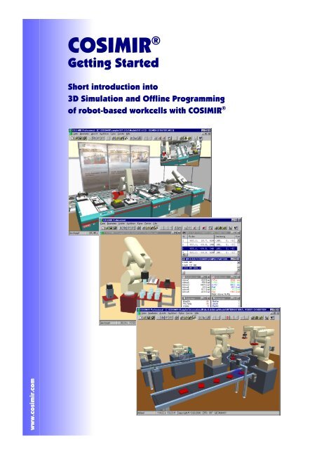
COSIMIR ®<br />
Getting Started<br />
Short introduction into<br />
3D Simulation and Offline Programming<br />
of robot-based workcells with COSIMIR ®<br />
www.cosimir.com
COSIMIR ® Getting Started 3<br />
Table of contents<br />
1. Introduction.......................................................................................................................... 5<br />
1.1 The 3D Simulation System COSIMIR ® .............................................................................. 5<br />
1.2 Text Formats...................................................................................................................... 5<br />
1.3 System Requirements ....................................................................................................... 6<br />
1.4 Installation Instructions ...................................................................................................... 7<br />
2. Operating............................................................................................................................ 13<br />
2.1 User Interface ..................................................................................................................13<br />
2.2 Window Types ................................................................................................................. 13<br />
3. Modeling............................................................................................................................. 17<br />
3.1 Model Hierarchy............................................................................................................... 17<br />
3.2 Model Libraries ................................................................................................................ 17<br />
3.3 Model Explorer................................................................................................................. 18<br />
3.4 Example: Workcell Modeling ........................................................................................... 19<br />
4. Programming .....................................................................................................................23<br />
4.1 Example: Workcell Programming .................................................................................... 23<br />
5. Simulation .......................................................................................................................... 27<br />
5.1 Settings ............................................................................................................................ 27<br />
5.2 Example: Workcell Simulation ......................................................................................... 28<br />
6. Mechanisms....................................................................................................................... 29<br />
6.1 Gripper ............................................................................................................................. 29<br />
6.2 Conveyor Belt .................................................................................................................. 29<br />
6.3 Push Cylinder...................................................................................................................30<br />
6.4 Rotary Drive..................................................................................................................... 30<br />
6.5 Turntable.......................................................................................................................... 31<br />
6.6 Two Way Push Cylinder .................................................................................................. 31<br />
6.7 Turning Mover.................................................................................................................. 32<br />
6.8 Parts Feeder ....................................................................................................................32<br />
6.9 Proximity Sensor.............................................................................................................. 33<br />
6.10 Replicator......................................................................................................................... 33<br />
6.11 Trash Can ........................................................................................................................ 33<br />
7. Extensions ......................................................................................................................... 35<br />
7.1 Collision Detection ........................................................................................................... 35<br />
7.2 Sensor Simulation............................................................................................................ 35<br />
7.3 Trajectory Generation ...................................................................................................... 35<br />
7.4 Process Simulation .......................................................................................................... 36<br />
7.5 PLC Simulation ................................................................................................................ 36<br />
7.6 Camera Cruise................................................................................................................. 36<br />
7.7 Action Object.................................................................................................................... 36<br />
8. Appendix ............................................................................................................................ 37<br />
8.1 Keyboard Usage .............................................................................................................. 37<br />
Copyright © 2000 · EFR · IRF (Nov-01)
4<br />
Getting Started<br />
COSIMIR ®<br />
8.2 Abbreviations ...................................................................................................................38<br />
8.3 Index ................................................................................................................................ 39<br />
Copyright © 2000 · EFR · IRF (Nov-01)
COSIMIR ® Getting Started 5<br />
1. Introduction<br />
This tutorial is suggested to be used for the first work with COSIMIR ® . It represents a<br />
short introduction into the 3D simulation and offline programming of robot-based<br />
workcells.<br />
1.1 The 3D Simulation System COSIMIR ®<br />
COSIMIR ® is the 3D-simulation system for Windows 95/98 and<br />
Windows NT/2000 operating systems.<br />
Use COSIMIR ® to plan robot-based workcells, to check the reachability of all<br />
positions, to develop programs for robots and controllers, and to optimize the workcell<br />
layout. All movements and handling operations can be simulated to avoid collisions and<br />
to optimize cycle times. The direct download of tested programs and positions into the<br />
robot controller is completely supported.<br />
The Modeling Extensions for COSIMIR ® support the composition of robot-based<br />
workcells. Efficient modeling is provided by using component libraries containing<br />
machinery, robots, tools, conveyor belts, part feeders, etc. Free 3D modeling and import<br />
from CAD systems (e. g. AutoCAD) are also possible.<br />
1.2 Text Formats<br />
Different text formats are used for certain text contents as well as for keyboard<br />
shortcuts.<br />
Text formats for plain text:<br />
The following typographical formats are used:<br />
Text Format<br />
bold<br />
italic<br />
CAPITALS<br />
"quotation marks"<br />
Used for<br />
Commands, menus, and dialog boxes.<br />
Enter text instead of the italic printed text.<br />
Acronyms, directoy and file names. You can use lower<br />
case letters, too.<br />
Options, chapter titles, and links.<br />
Text formats for keyboard shortcuts:<br />
The following typographical formats are used:<br />
Text Format<br />
KEY1+KEY2<br />
KEY1-KEY2<br />
Means<br />
If you have to press two keys at the same time a plus sign<br />
(+) is printed between the two keys.<br />
If you have to press two keys one after another a minus<br />
sign (-) is printed between the two keys.<br />
Copyright © 2000 · EFR · IRF (Nov-01)
6<br />
Getting Started<br />
COSIMIR ®<br />
1.3 System Requirements<br />
Minimum Requirements<br />
Processor:<br />
Pentium 133 MHz Processor or higher<br />
Memory:<br />
64 MB RAM<br />
Harddisk:<br />
200 MB free<br />
Operating System: Windows 95/98<br />
Windows NT/2000<br />
Graphic Adapter: any card supported, 3D acceleration increases performance<br />
Recommended Configuration<br />
Processor:<br />
Pentium II 300 MHz Processor or higher<br />
Memory:<br />
128 MB RAM<br />
Harddisk:<br />
200 MB free<br />
Operating System: Windows 95/98<br />
Windows NT/2000<br />
Graphic Adapter: Adapter with 3D acceleration and OpenGL support<br />
High-End Configuration<br />
Processor:<br />
Pentium III 800 MHz-Processor<br />
Memory:<br />
256 MB RAM<br />
Harddisk:<br />
200 MB free<br />
Operating System: Windows NT/2000<br />
Graphic Adapter: Adapter with 3D acceleration and OpenGL support,<br />
GeFORCE II chip set<br />
Copyright © 2000 · EFR · IRF (Nov-01)
COSIMIR ® Getting Started 7<br />
1.4 Installation Instructions<br />
To install COSIMIR ® run “SETUP.EXE“ from the installation CD. The installation<br />
wizard will guide you through the installation.<br />
Important notice: It is necessary to install a device driver to use the hardlock.<br />
Running WINDOWS NT or WINDOWS 2000 you need administrator privilegies to<br />
install this device driver.<br />
Use the first dialog to select the desired language.<br />
Next are further instructions and license agreements.<br />
Copyright © 2000 · EFR · IRF (Nov-01)
8<br />
Getting Started<br />
COSIMIR ®<br />
Use the following dialog to select the drive and path in which to install COSIMIR ® in.<br />
You may install the different options of COSIMIR ® shown in the next dialog. The dialog<br />
may differ for different COSIMIR ® versions as the installation contains version and user<br />
specific components.<br />
Copyright © 2000 · EFR · IRF (Nov-01)
COSIMIR ® Getting Started 9<br />
If you are installing a version of COSIMIR ® supporting communication to real robots,<br />
the following dialog allows to select the serial interface port and the robot type.<br />
COSIMIR ® creates a program group for the Windows program manager and the start<br />
menu. Use the following dialog to choose a name.<br />
Copyright © 2000 · EFR · IRF (Nov-01)
10<br />
Getting Started<br />
COSIMIR ®<br />
After these information the installations starts.<br />
The COSIMIR ® online help is based on the standard HTML help format of Windows.<br />
To use this Microsoft Internet Explorer of version 3.0 or higher is necessary. It is not<br />
possible to use the COSIMIR ® online help without a Microsoft Internet Explorer installed<br />
on your system.<br />
If necessary the HTML help system is updated.<br />
Copyright © 2000 · EFR · IRF (Nov-01)
COSIMIR ® Getting Started 11<br />
COSIMIR ®<br />
automatically.<br />
uses a hardlock and the drivers for this hardlock are installed<br />
Installation is completed now. See “README.TXT“ for further information.<br />
If having installed the hardlock driver a system restart is necessary to run COSIMIR ® .<br />
Copyright © 2000 · EFR · IRF (Nov-01)
12<br />
Getting Started<br />
COSIMIR ®<br />
Copyright © 2000 · EFR · IRF (Nov-01)
COSIMIR ® Getting Started 13<br />
2. Operating<br />
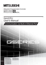
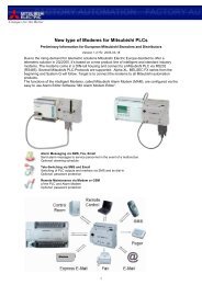
2.1 User Interface<br />
This chapter shows the first steps in using COSIMR ® .<br />
Inputs/Outputs<br />
TeachIn Window<br />
Menu Bar<br />
Workcell Window<br />
Joint/World Coordinates<br />
Controller Selection<br />
Toolbar<br />
Status Bar<br />
Mitsubishi Program<br />
Adept Program<br />
User Input/Output<br />
Mitsubishi Position List<br />
Adept Position List<br />
Second<br />
Workcell Window<br />
2.2 Window Types<br />
The most important window types of the COSIMIR ® user interface are specified in the<br />
following list.<br />
Workcell Window<br />
The workcell is shown graphically in the workcell view<br />
window. You can open further windows with different workcell<br />
views by means of the command New from the View menu.<br />
Joint Coordinates<br />
The window joint coordinates shows the positions of the<br />
single robot joints. The display unit for rotational joints is<br />
degrees, for linear joints it is millimeters. A double click into this<br />
window opens the dialog box Set Joint Coordinates.<br />
Copyright © 2000 · EFR · IRF (Nov-01)
14<br />
Getting Started<br />
COSIMIR ®<br />
command Show Joint Coordinates from the Extras/Robot<br />
Position menu.<br />
World Coordinates<br />
The window world coordinates displays the position and<br />
orientation of the Tool Center Points in world coordinates. In<br />
addition, position, orientation, and configuration of the robot are<br />
displayed in the lowest line of the window. A double-click on this<br />
window opens the dialog box Set World Coordinates.<br />
To open the window world coordinates press, SHIFT+F7 or<br />
choose the command Show World Coordinates from the<br />
Extras/Robot Position menu.<br />
Teach-In<br />
The window Teach-In (Joint Coordinates) contains the names<br />
of the robot joints and two small buttons to move the individual<br />
joints of the robot. Thereby the reaction of a real robot is<br />
simulated. If you keep pushing the button, the robot accelerates<br />
up to the adjusted speed (Override), keeps the speed steadily<br />
and then continuously decelerates to a speed of 0 after releasing<br />
the button.<br />
Select the jog operation mode to change to Teach-In in world<br />
coordinates or tool coordinates.<br />
To open the window Teach-In press F8 or choose the<br />
command Show World Coordinates from the Extras/Robot<br />
Position menu.<br />
Inputs/Outputs<br />
The window Inputs/Outputs shows the states of the simulated<br />
robot-controller’s inputs/outputs. The current states of the<br />
inputs/outputs are displayed next to their names. 0-signals are<br />
displayed in red color, 1-signals are displayed in green color.<br />
The value of an input is displayed in brackets, i. e. [1], if the<br />
input is connected to an output. If the signal of the input is<br />
forced, the value of the input is displayed in angle brackets, i. e.<br />
.<br />
To open the window Inputs/Outputs press F9/CTRL+F9 or<br />
choose the command Show Inputs/Show Outputs from the<br />
Extras/Inputs/Outputs menu.<br />
Controller Selection<br />
The window Controller Selection shows the states of all<br />
controllers of the workcell. You are able to choose the master<br />
controller and to observe the activity of the different controllers.<br />
Display of robot positions, inputs, outputs and teach-in is always<br />
done for the emphasized robot (master).<br />
To open the window Controller Selection choose the<br />
command Controller Selection from the Execute menu.<br />
Copyright © 2000 · EFR · IRF (Nov-01)
COSIMIR ® Getting Started 15<br />
Robot Program<br />
This window shows a high level program in the native<br />
programming language of a robot. The window title contains the<br />
name of the associated robot.<br />
Choose the command Open from the File menu to open a<br />
robot program or create a new program by choosing command<br />
new from the File menu.<br />
Position List<br />
This window shows a position list of a robot. The window title<br />
contains the name of the associated robot.<br />
Choose the command Open from the File menu to open a<br />
position list or create a new position list by choosing command<br />
New from the File menu.<br />
User Input/Output<br />
The User Input/Output window opens automatically if the<br />
robot program contains commands for reading and writing of<br />
data via the serial interface to and from the robot control.<br />
Because of the simulation of a robot control, the data is not<br />
sent physically via the serial interface, but it is sent to the User<br />
Input/Output window where the data is displayed.<br />
Copyright © 2000 · EFR · IRF (Nov-01)
16<br />
Getting Started<br />
COSIMIR ®<br />
Copyright © 2000 · EFR · IRF (Nov-01)
COSIMIR ® Getting Started 17<br />
3. Modeling<br />
There are several tools (i. e. model libraries and the Model Explorer for COSIMIR ® )<br />
providing a comfortable modeling of robot-based workcells. By means of a simple<br />
example workcell, a short introduction in workcell modeling is given in this chapter.<br />
3.1 Model Hierarchy<br />
The COSIMIR ® model hierarchy contains the following element types:<br />
Objects<br />
Sections<br />
The highest unit in the element structure are the<br />
objects.<br />
Example: A robot is an object.<br />
Sections are assigned to objects. One degree-offreedom<br />
can be associated to each section that is<br />
moveable relatively to the previous section.<br />
Example: Each joint of a robot is a section.<br />
Hulls Hulls are assigned to sections and are<br />
responsible for the graphical representation.<br />
Example: A face, a box or a polyhedron are hulls.<br />
Gripper Points<br />
Grip Points<br />
An object needs a gripper point to grasp other<br />
objects. Gripper points are assigned to sections.<br />
Example: At the flange of a robot a gripper point<br />
is modeled.<br />
To be grasped by another object an object needs<br />
a grip point. Grip points are assigned to sections.<br />
Example: A grip point is associated to a work<br />
piece that has to be grasped.<br />
3.2 Model Libraries<br />
There is wide range of partly optional model libraries for COSIMIR ® . Use these model<br />
libraries to add new objects or model parts to a workcell model.<br />
The following model libraries are available:<br />
Robots<br />
ABB<br />
Adept<br />
Fanuc<br />
Kuka<br />
Manutec<br />
Mitsubishi<br />
Niko<br />
Reis<br />
Stäubli<br />
VW<br />
Miscellaneous<br />
Miscellaneous<br />
Grippers<br />
Primitives<br />
LEDs<br />
Materials<br />
Mechanisms<br />
Sensors<br />
Textures<br />
Additional Axes<br />
The dialog box Model Libraries can be opened as follows:<br />
Copyright © 2000 · EFR · IRF (Nov-01)
18<br />
Getting Started<br />
COSIMIR ®<br />
Menu<br />
Toolbar<br />
Execute/Model Libraries<br />
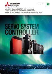
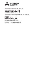
3.3 Model Explorer<br />
Use the Model Explorer to access all the elements of a workcell. Besides objects and<br />
associated elements you are able to maintain materials, libraries, lighting sources, and<br />
I/O connections, too.<br />
The Model Explorer’s<br />
window is divided into two parts.<br />
In the left area a navigation<br />
tree contains folders with the<br />
different elements of a workcell.<br />
If you select a folder in the<br />
navigation tree the element list<br />
in the right area of the Model<br />
Explorer is filled with the folder’s<br />
elements.<br />
To access an element select<br />
the element in the navigation<br />
tree or in the element list by<br />
clicking on the element using<br />
the mouse.<br />
Navigation Tree<br />
Element List<br />
By clicking the right mouse button or pressing the context menu key on a<br />
Windows 95 keyboard you can open a context menu with most important commands<br />
depending on the current element selection.<br />
Choose command Model Explorer from the Extras/Settings menu to configure the<br />
appearance of the Model Explorer.<br />
The Model Explorer can be opened as follows:<br />
Menu<br />
Toolbar<br />
Keyboard<br />
Execute/Model Explorer<br />
CTRL+T<br />
Copyright © 2000 · EFR · IRF (Nov-01)
COSIMIR ® Getting Started 19<br />
3.4 Example: Workcell Modeling<br />
In this chapter modeling of a simple workcell is described step by step. Programming<br />
and simulation of this workcell are described in the next chapters.<br />
Choose command New<br />
Workcell from the File menu to<br />
create a new workcell. Specify the<br />
filename (e. g. “Example.mod”) for<br />
the new workcell.<br />
After creating the new workcell<br />
you are able to specify a different<br />
workcell name as well as properties<br />
for the workcell (e. g. background<br />
color, floor color, and floor size).<br />
Use the dialog Properties for<br />
workcell while the workcell name is<br />
selected in the Model Explorer to<br />
change workcell properties.<br />
Open dialog box Model<br />
Libraries by choosing command<br />
Model Libraries from the Execute<br />
menu or clicking the button in<br />
the toolbar.<br />
Select the Mitsubishi Robot<br />
RV-2AJ from library “Mitsubishi<br />
Robots” and click Add.<br />
The robot is the first object in the<br />
workcell and is displayed in the<br />
Model Explorer.<br />
In the Model Explorer select the<br />
digital Output (Index 000) of the<br />
robot and press F2 to activate and<br />
to rename the output to “Grasp”.<br />
Copyright © 2000 · EFR · IRF (Nov-01)
20<br />
Getting Started<br />
COSIMIR ®<br />
Select the Parallel Gripper<br />
(simple) of library “Miscellaneous<br />
Grippers” in dialog box Model<br />
Libraries and click Add. The<br />
gripper is attached to the robot’s<br />
flange automatically.<br />
To simulate the electrical<br />
connection between the robot<br />
controller and the gripper, drag the<br />
input Close of the gripper from the<br />
element list of the Model Explorer<br />
and drop it to the output Grasp of<br />
the robot in the navigation tree.<br />
Now the gripper can be controlled<br />
by the robot controller.<br />
Add a box from the model library<br />
“Miscellaneous Primitives” to the<br />
workcell.<br />
Edit the element properties in<br />
dialog box Properties for object<br />
as follows:<br />
Pos. (x,y,z): 200 mm, -150 mm, 0 mm<br />
Dim. (x,y,z): 200 mm, 300 mm, 250 mm<br />
Visualization: Dark blue<br />
Note, that dialog box Properties<br />
for elements contains the properties<br />
of the currently selected element<br />
(workcell, object, etc.).<br />
In the Model Explorer rename<br />
the object “Box” to “Table”.<br />
Select the object Table in the<br />
Model Explorer and press CTRL+C to<br />
copy the object to the clipboard.<br />
Select the folder Objects and press<br />
CTRL+V to paste the object from the<br />
clipboard.<br />
Rename the copied object<br />
“Table_1” to “Workpiece” and edit<br />
its properties as follows:<br />
Pos. (x,y,z): 275 mm, 0 mm, 250 mm<br />
Dim. (x,y,z): 50 mm, 50 mm, 50 mm<br />
Visualization: Red<br />
To let a workpiece be grasped<br />
by a robot you have to assign a grip<br />
point to the workpiece.<br />
Copyright © 2000 · EFR · IRF (Nov-01)
COSIMIR ® Getting Started 21<br />
Add a grip point to the workpiece<br />
by choosing the command<br />
New/Grip Point from the context<br />
menu of the Model Explorer. To<br />
open the appropriate context menu<br />
select the section Base of the<br />
object Workpiece and press the<br />
right mouse button. Rename the<br />
grip point to “Workpiece”.<br />
Edit the position and orientation<br />
of the grip point relatively to the<br />
section coordinate system in dialog<br />
box Properties for grip point as<br />
follows.<br />
Pos. (x,y,z): 25 mm, 25 mm, 25 mm<br />
Ori. (r,p,y): 180°, 0°, 180°<br />
Now, the grip point is in the<br />
center of the workpiece.<br />
At last save the workcell by choosing command Save from the File menu or by<br />
clicking button in the toolbar.<br />
You can open the modeled workcell from the following installation directory of<br />
COSIMIR ® :<br />
\GettingStarted\Mitsubishi\Modeling\Example.mod<br />
Example: C:\COSIMIR\GettingStarted\Mitsubishi\Modeling\Example.mod<br />
The next chapter contains an example of programming the created workcell.<br />
Copyright © 2000 · EFR · IRF (Nov-01)
22<br />
Getting Started<br />
COSIMIR ®<br />
Copyright © 2000 · EFR · IRF (Nov-01)
COSIMIR ® Getting Started 23<br />
4. Programming<br />
For programming of robots the native programming language of the robots is used in<br />
COSIMIR ® .<br />
4.1 Example: Workcell Programming<br />
This example shows the programming of the robot. The workcell modeled in the<br />
previous chapter is used.<br />
Choose command Open from<br />
the File menu to open the example<br />
workcell of the previous chapter.<br />
Create a new MRL position list<br />
by choosing command New from<br />
the File menu and selecting item<br />
MRL Position List in dialog box<br />
New.<br />
You are able to open dialog box<br />
new by clicking button in the<br />
toolbar or by using the shortcut<br />
CTRL+N.<br />
Close the Model Explorer and<br />
the dialog box Properties for<br />
elements.<br />
Accept the initial position of the<br />
robot as first position of the position<br />
list. Use the shortcut CTRL+F2 to<br />
accept current robot positions in<br />
position lists.<br />
Select the last free entry in the<br />
position list and use the shortcut<br />
CTRL+F2 a second time. This position<br />
has to be changed. Select the<br />
position by clicking on the entry with<br />
the left mouse button and choose<br />
command Properties from the<br />
Edit menu to open dialog box<br />
Position List Entry. Change the<br />
position as follows:<br />
Position (x,y,z): 300 mm, 25 mm, 275 mm<br />
Orientation (A/P, B/R): 0°, 180°<br />
Copyright © 2000 · EFR · IRF (Nov-01)
24<br />
Getting Started<br />
COSIMIR ®<br />
Open dialog box Grip by<br />
choosing command Grip from the<br />
Extras/Settings menu. Select<br />
output Grasp in list Gripper<br />
Control at Teach-In and press OK.<br />
Press F8 to open the window<br />
Teach-In. Click at Close Hand to<br />
control the gripper with the window<br />
Teach-In. Confirm all messages<br />
regarding to warnings that no object<br />
is near the gripper or is being<br />
grasped. These warnings can be<br />
switched off.<br />
Double click on the entry<br />
position P2 in the position list to<br />
move the robot to this position. Let<br />
the robot grasp the workpiece by<br />
clicking Close Hand in window<br />
Teach-In.<br />
Select XYZ Jog and click the<br />
button for movement in negative<br />
Y-direction. The robot is moving the<br />
workpiece across the table. Save<br />
the new robot position in the<br />
position list by selecting the last<br />
free entry and using the shortcut<br />
CTRL+F2.<br />
Save the position list as<br />
“Mitsubishi.pos”.<br />
Choose command Reset<br />
Workcell from the Edit menu.<br />
Copyright © 2000 · EFR · IRF (Nov-01)
COSIMIR ® Getting Started 25<br />
Create a new MELFA Basic IV<br />
Programm by choosing command<br />
New from the File menu and<br />
develop a program executing a<br />
simple Pick and Place task using<br />
the positions P1 to P3 of the<br />
position list.<br />
Note, that the correct index of<br />
the output is used for control of the<br />
gripper.<br />
The positions above the pick<br />
and the place positions shall be<br />
determined relatively.<br />
See that a line feed is needed at<br />
the end of the program.<br />
After programming save the<br />
program as „Mitsubishi.mb4“<br />
For the purpose of simulation<br />
the program as well as the position<br />
list are integrated into a MELFA<br />
Basic project.<br />
Create a new MELFA Basic IV<br />
project in dialog box Project<br />
Management (command Project<br />
Management from Execute menu).<br />
Choose command Add Project or<br />
click button to add a new project<br />
named “Mitsubishi.prj”.<br />
In page Files of the dialog box<br />
add the program and the position<br />
list by clicking button and<br />
selecting the files. Declare the<br />
program “Mitsubishi.mb4” as Main<br />
Program.<br />
The program is integrated into<br />
the current project.<br />
Close dialog box Project<br />
Management and activate the<br />
program window. Choose<br />
command Compile+Link from the<br />
Execute menu (CTRL+F9 or<br />
button ) to check the project and<br />
to load it into the simulated robot<br />
controller.<br />
In window Messages all used<br />
system modules, program modules,<br />
and position lists as well as errors<br />
and warnings are displayed.<br />
You have developed an executable robot program for the workcell simulation.<br />
Copyright © 2000 · EFR · IRF (Nov-01)
26<br />
Getting Started<br />
COSIMIR ®<br />
You can open the programmed workcell from the following installation directory of<br />
COSIMIR ® :<br />
\GettingStarted\Mitsubishi\Programming\Example.mod<br />
Example: C:\COSIMIR\GettingStarted\Mitsubishi\Programming\Example.mod<br />
The next chapter contains an example of simulating the modeled and programmed<br />
workcell.<br />
Copyright © 2000 · EFR · IRF (Nov-01)
COSIMIR ® Getting Started 27<br />
5. Simulation<br />
5.1 Settings<br />
This chapter contains the simulation of programs developed offline in COSIMIR ® .<br />
Choose the command Simulation from the execute menu to configure the<br />
simulation settings with the dialog box Simulation.<br />
Simulation with constant simulation cycle<br />
The difference of simulation time between the graphical updates of the<br />
workcell window is called simulation cycle. The shorter you choose the<br />
time for a simulation cycle, the smoother but also slower is the animation.<br />
The controller cycle is the time used to update the internal system<br />
values like interpolation steps of robots or I/O update cycles of PLCs. The<br />
Simulation Cycle mentioned above is always a multiple of this controller<br />
cycle.<br />
If you select the option Show End Position the final position of a<br />
movement will always be displayed in the animation. If you select the<br />
option Skip Waiting Time the waiting times in the robot program are<br />
simulated faster.<br />
The selection Model Update switches the update of model calculations<br />
like belts or process simulation from the very small cycle Controller Cycle<br />
to Simulation Cycle. The setting Controller Cycle may lead to decreasing<br />
performance for some models, on the other hand Simulation Cycle may<br />
evaluate to some inaccuracies.<br />
Simulation with dynamic simulation<br />
Choose Realtime to start a simulation with a dynamic simulation cycle<br />
that is controlled respectively to the real time to reach a synchronization<br />
between the simulation time and the real clock.<br />
Configure a Maximum Simulation Cycle to limit the simulation cycle. In<br />
case of complex workcell models or PCs without enough performance the<br />
system might try to increase the simulation cycle continuously. The value<br />
entered here is the upper limit to be set.<br />
The parameter Realtime Compensation Parameter determines the<br />
constant (amplification P) to control the simulation cycle. Values range<br />
from 0.1 to 0.6. A small value means a slower compensation, higher<br />
values may force fluctuations or even oscillations.<br />
Copyright © 2000 · EFR · IRF (Nov-01)
28<br />
Getting Started<br />
COSIMIR ®<br />
5.2 Example: Workcell Simulation<br />
Open the example workcell of the previous chapters.<br />
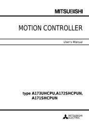
To start simulation choose<br />
command Start from the Execute<br />
menu.<br />
The program is simulated step<br />
by step. The simulation time is<br />
displayed in the status bar.<br />
Because of the source code<br />
sequence trace the currently<br />
executed command is highlighted in<br />
the program window.<br />
Before you start simulation a<br />
second time choose command<br />
Reset Workcell from the Edit<br />
menu. This command resets all<br />
objects as well as the robot<br />
Copyright © 2000 · EFR · IRF (Nov-01)
COSIMIR ® Getting Started 29<br />
6. Mechanisms<br />
6.1 Gripper<br />
In COSIMIR ® the simulation of so called base mechanisms is a powerful feature for<br />
simulation of workcells. A mechanism is assigned to an object using the object’s type.<br />
Depending on the mechanism the object structure (concerning number of I/Os, number<br />
and configuration of sections and joints) is given. The mechanism can only be simulated<br />
correctly if the given object structure exists.<br />
To model a mechanism, use the model libraries. Add an object with a mechanism to<br />
the workcell to guarantee that the object structure is correct. Afterwards, change the<br />
shape as well as the dynamics and I/O names of the object to model your own<br />
mechanism.<br />
Please note that to control any of the mechanisms the input values have to change<br />
from low to high to start the mechanism. Moreover the output values containing the state<br />
of the mechanisms are only updated if the outputs are connected to an input.<br />
Use the gripper mechanism to simulate grasping of workpieces. If system input 0 of<br />
the gripper object is set to high, the gripper grasps an object that has a free grip point in<br />
the grip range of the gripper’s gripper point. All sections of the gripper object that have a<br />
degree of freedom are moved to their upper limits. Thus the movement of gripper chucks<br />
is simulated.<br />
Mechanism<br />
Object Type<br />
Gripper<br />
Gripper<br />
System Inputs/Outputs<br />
Examples<br />
6.2 Conveyor Belt<br />
Inputs<br />
Outputs<br />
Object<br />
Parallel Gripper<br />
Three Jaw Gripper<br />
Index Type Value Description<br />
000 digital 1 Closes the gripper.<br />
0 Opens the gripper.<br />
Index Type Value Description<br />
000 digital<br />
0 Gripper is not closed.<br />
1 Gripper is closed.<br />
Model Library<br />
Miscellaneous Grippers<br />
Miscellaneous Grippers<br />
If there is another object with a free grip point above a conveyer belt object, the object<br />
is moved along the active surface of the conveyor belt if the grip point lies inside the grip<br />
range of the active surface. This only works if system input 0 of the conveyor belt is set to<br />
high. If the object is moved up to the end of the active surface system output 0 is set to<br />
high.<br />
Mechanism<br />
Conveyor Belt<br />
Object Type<br />
Conveyor Belt<br />
Copyright © 2000 · EFR · IRF (Nov-01)
30<br />
Getting Started<br />
COSIMIR ®<br />
System Inputs/Outputs<br />
Examples<br />
Inputs<br />
Outputs<br />
Object<br />
Conveyor Belt<br />
Index Type Value Description<br />
000 digital 1 Switches the conveyor belt on.<br />
0 Switches the conveyor belt off.<br />
001 digital 1 Conveyor belt transports backwards.<br />
0 Conveyor belt transports forward.<br />
Index Type Value Description<br />
000 digital 0 There is no object at conveyor’s end.<br />
1 There is an object at conveyor’s end.<br />
Model Library<br />
Miscellaneous Mechanisms<br />
6.3 Push Cylinder<br />
The push cylinder is extended if system input 0 is set to high. If there is an object with<br />
a free grip point in the grip range of the push cylinder’s gripper point the object is moved<br />
by the push cylinder. The push cylinder is retracted if system input 0 is set to low.<br />
Mechanism<br />
Push Cylinder<br />
Object Type<br />
Push Cylinder<br />
System Inputs/Outputs<br />
Inputs Index Type Value Description<br />
000 digital 1 Extends the push cylinder.<br />
0 Retracts the push cylinder.<br />
Outputs Index Type Value Description<br />
000 digital 0 Push cylinder is not extended.<br />
1 Push cylinder is extended.<br />
Examples<br />
Object<br />
Model Library<br />
Push Cylinder<br />
Miscellaneous Mechanisms<br />
6.4 Rotary Drive<br />
The mechanism rotary drive is based on the push cylinder mechanism.<br />
Mechanism<br />
Rotary Drive<br />
Object Type<br />
Rotary Drive<br />
System Inputs/Outputs<br />
Inputs Index Type Value Description<br />
000 digital 1 Rotary Drive moves to upper limit.<br />
0 Rotary Drive moves to lower limit.<br />
Outputs Index Type Value Description<br />
000 digital 0 Rotary Drive is not at upper limit.<br />
1 Rotary Drive is at upper limit.<br />
Examples<br />
Copyright © 2000 · EFR · IRF (Nov-01)
COSIMIR ® Getting Started 31<br />
Object<br />
Rotary Drive<br />
Model Library<br />
Miscellaneous Mechanisms<br />
6.5 Turntable<br />
All axes of turntable object are moved to the upper limits if system input 0 is set to<br />
high. If there is an object with a free grip point inside the grip range of the turntable’s<br />
active surface the object is moved with the turntable.<br />
Mechanism<br />
Turntable<br />
Object Type<br />
Turntable<br />
System Inputs/Outputs<br />
Inputs<br />
Outputs<br />
Examples<br />
Object<br />
Turntable<br />
Index Type Value Description<br />
000 digital 1 Turns the turntable.<br />
0 -<br />
Index Type Value Description<br />
000 digital 0 Turntable is moving.<br />
1 Turntable stand still.<br />
Model Library<br />
Miscellaneous Mechanisms<br />
6.6 Two Way Push Cylinder<br />
The function of the two way push cylinder is similar to the function of the push<br />
cylinder. For the purpose of control there are two system inputs. According to this there<br />
are two system outputs for the cylinder’s state.<br />
Mechanism<br />
Two Way Push Cylinder<br />
Object Type<br />
Two Way Push Cylinder<br />
System Inputs/Outputs<br />
Inputs Index Type Value Description<br />
000 digital 1 Extends the push cylinder.<br />
0 -<br />
001 digital 1 Retracts the push cylinder.<br />
0 -<br />
Outputs Index Type Value Description<br />
000 digital 0 Push cylinder is not extended.<br />
1 Push cylinder is extended.<br />
001 digital 0 Push cylinder is not retracted.<br />
1 Push cylinder is retracted.<br />
Examples<br />
Object<br />
Model Library<br />
Two Way Push Cylinder<br />
Miscellaneous Mechanisms<br />
Copyright © 2000 · EFR · IRF (Nov-01)
32<br />
Getting Started<br />
COSIMIR ®<br />
6.7 Turning Mover<br />
The turning mover consists of two sections and a vacuum gripper that can be<br />
controlled by setting system inputs 2 and 3. Use system inputs 0 and 1 to control the<br />
position of the turning mover.<br />
Mechanism<br />
Object Type<br />
Turning Mover<br />
Turning Mover<br />
System Inputs/Outputs<br />
Examples<br />
Inputs<br />
Outputs<br />
Object<br />
Turning Mover<br />
Index Type Value Description<br />
000 digital 1 Moves to position A.<br />
0 -<br />
001 digital 1 Moves to position B.<br />
0 -<br />
002 digital 1 Grasp<br />
0 -<br />
003 digital 1 Release<br />
0 -<br />
Index Type Value Description<br />
000 digital<br />
001 digital<br />
0 Turning mover is not at position A.<br />
1 Turning mover is at position A.<br />
0 Turning mover is not at position B.<br />
1 Turning mover is at position B.<br />
Model Library<br />
Miscellaneous Mechanisms<br />
6.8 Parts Feeder<br />
Use the mechanism parts feeder to model depots for workpieces etc. The associated<br />
object contains a whole string of gripper points. The sequence of these gripper points is<br />
important for the function of the parts feeder that is filled by moving objects with free grip<br />
points in the grip range of the feeder’s gripper points. Note that the first of the feeder’s<br />
gripper points must not be covered. In case of setting system input 0 of the parts feeder<br />
to high the object at the second gripper point is moved to the first gripper point, the object<br />
at the third gripper point is moved to the second gripper point etc. If there is an object at<br />
the position of the first gripper point system output 0 is set to high.<br />
Mechanism<br />
Parts Feeder<br />
Object Type<br />
Parts Feeder, optional “with Gravity”<br />
System Inputs/Outputs<br />
Inputs Index Type Value Description<br />
000 digital 1 Requests a new part.<br />
0 -<br />
Outputs Index Type Value Description<br />
000 digital 0 No part is available.<br />
1 There is a part available.<br />
Examples<br />
Copyright © 2000 · EFR · IRF (Nov-01)
COSIMIR ® Getting Started 33<br />
Object<br />
Parts Feeder 1<br />
Parts Feeder 2<br />
Model Library<br />
Miscellaneous Mechanisms<br />
Miscellaneous Mechanisms<br />
6.9 Proximity Sensor<br />
This simple proximity sensor checks if there is an object with a free grip point in the<br />
grip range of the sensor’s gripper point.<br />
Mechanism<br />
Object Type<br />
Proximity Sensor<br />
Proximity Sensor<br />
System Inputs/Outputs<br />
Examples<br />
Outputs<br />
Object<br />
Proximity Sensor<br />
Index Type Value Description<br />
000 digital<br />
0 No grip point detected.<br />
1 Grip point detected.<br />
Model Library<br />
Miscellaneous Mechanisms<br />
6.10 Replicator<br />
Use the replicator mechanism for creation of new objects based on templates. The<br />
extended properties of the replicator object contain the assignment of system inputs and<br />
templates (example; template 0 = “Workpiece”). If a system input is set to high, a new<br />
object based on the associated template is created at the gripper point of the replicator<br />
object.<br />
Mechanism<br />
Replicator<br />
Object Type<br />
Replicator<br />
System Inputs/Outputs<br />
Inputs<br />
Examples<br />
Object<br />
Replicator<br />
Index Type Value Description<br />
000 digital 1 Create first configured object.<br />
0 -<br />
001 digital 1 Create second configured object.<br />
0 -<br />
... ... ... ...<br />
00n digital 1 Create n-th configured object.<br />
0 -<br />
Model Library<br />
Miscellaneous Mechanisms<br />
6.11 Trash Can<br />
The trash can is the counterpart of the replicator. Use the mechanism trash can to<br />
remove objects at runtime. Each system input of the trash can object is associated to a<br />
gripper point. If system input 1 is set to high and there is an object with a free grip point<br />
inside the grip range of grip point 1 of the trash can object, the object is removed.<br />
Copyright © 2000 · EFR · IRF (Nov-01)
34<br />
Getting Started<br />
COSIMIR ®<br />
Please note that all objects that have been removed by this mechanism are not<br />
recovered by choosing command Reset Workcell from the Edit menu.<br />
Mechanism<br />
Trash Can<br />
Object Type<br />
Trash Can<br />
System Inputs/Outputs<br />
Inputs<br />
Examples<br />
Object<br />
Trash Can<br />
Index Type Value Description<br />
000 digital 1 Remove object at gripper point 1.<br />
0 -<br />
001 digital 1 Remove object at gripper point 2.<br />
0 -<br />
... ... ... ...<br />
00n digital 1 Remove object at gripper point n.<br />
0 -<br />
Model Library<br />
Miscellaneous Mechanisms<br />
Copyright © 2000 · EFR · IRF (Nov-01)
COSIMIR ® Getting Started 35<br />
7. Extensions<br />
The basic functionality of COSIMIR ®<br />
important extensions are described.<br />
can be extended. In this chapter the most<br />
7.1 Collision Detection<br />
By the Collision Detection you are able to detect collisions in your workcell. Single<br />
objects can be selected for checking. Objects which collide are colored and collision<br />
messages are output.<br />
Availability Industry Education<br />
COSIMIR ® Professional <br />
COSIMIR ® Industrial <br />
COSIMIR ® Educational - <br />
7.2 Sensor Simulation<br />
The sensor simulation extends the capability of COSIMIR to simulate complete<br />
workcells. Many sensors used in production automation can be parametered and<br />
simulated realistically. Moreover the visualization of measuring ranges helps to prevent<br />
errors in the planning stage. This cannot be done in reality.<br />
Availability Industry Education<br />
COSIMIR ® Professional <br />
COSIMIR ® Industrial not available not available<br />
COSIMIR ® Educational - <br />
7.3 Trajectory Generation<br />
This extension for COSIMIR ® provides an automatic face-oriented trajectory<br />
generation which is a powerful functionality for developing robot programs for coating and<br />
ablation processes. Using this feature the effort for programming is minimized as well as<br />
the results are optimized.<br />
Availability Industry Education<br />
COSIMIR ® Professional optional optional<br />
COSIMIR ® Industrial not available not available<br />
COSIMIR ® Educational - <br />
Copyright © 2000 · EFR · IRF (Nov-01)
36<br />
Getting Started<br />
COSIMIR ®<br />
7.4 Process Simulation<br />
This module for simulating coating and ablation processes enables the programmer of<br />
a robotic task to optimize the course of production already during the creation of the<br />
program. Moreover he can visually judge the qualitative result of the treatment at the<br />
same time. Thus lengthy tests of a movement program with test objects are not<br />
necessary and the effort for offline-programming is minimized. At the same time the<br />
results of the treatment process are improved.<br />
Availability Industry Education<br />
COSIMIR ® Professional optional optional<br />
COSIMIR ® Industrial not available not available<br />
COSIMIR ® Educational - <br />
7.5 PLC Simulation<br />
With the PLC-S5/S7 Simulator for COSIMIR ® S5/S7 programs can be interpreted.<br />
Several PLCs can be modeled in each workcell. While loading a PLC in a workcell the<br />
corresponding PLC program is loaded, too. You are able to change or edit this PLC<br />
program.<br />
Availability Industry Education<br />
COSIMIR ® Professional optional <br />
COSIMIR ® Industrial not available not available<br />
COSIMIR ® Educational - <br />
7.6 Camera Cruise<br />
The Camera Cruise for COSIMIR ® provides the saving of different views of a workcell.<br />
During simulation these views are recovered in rotation. A new view between two views is<br />
determined by linear interpolation. Thus the viewpoint moves uniformly. You can also<br />
save a Camera Cruise in a video file (Windows-AVI).<br />
Availability Industry Education<br />
COSIMIR ® Professional <br />
COSIMIR ® Industrial not available not available<br />
COSIMIR ® Educational - <br />
7.7 Action Object<br />
Use Action Objects in COSIMIR ® to execute different actions because of output values<br />
of any object. To configure the inputs of an Action Object change the Properties for input.<br />
Possible actions are output of message, display of pictures and HTML pages, switching<br />
of light sources as well as playback of audio and video files.<br />
Availability Industry Education<br />
COSIMIR ® Professional optional optional<br />
COSIMIR ® Industrial not available not available<br />
COSIMIR ® Educational - <br />
Copyright © 2000 · EFR · IRF (Nov-01)
COSIMIR ® Getting Started 37<br />
8. Appendix<br />
8.1 Keyboard Usage<br />
Key<br />
SHIFT+F5<br />
SHIFT+F4<br />
ALT+F4<br />
F7<br />
SHIFT+F7<br />
F8<br />
F9<br />
SHIFT+F9<br />
CTRL+N<br />
CTRL+O<br />
SHIFT+F12<br />
F12<br />
CTRL+P<br />
CTRL+A<br />
ALT+EINGABE<br />
CTRL+X<br />
CTRL+C<br />
CTRL+V<br />
CTRL+K<br />
CTRL+E<br />
CTRL+T<br />
Shortcut<br />
Cascade windows.<br />
Tile windows.<br />
Quit the program.<br />
Displays the joint values of the robot.<br />
Displays the tool coordinates in world coordinates.<br />
Displays the window Teach-In<br />
Displays the input signals.<br />
Displays the output signals.<br />
Command File New<br />
Command File Open<br />
Command File Save<br />
Command File Save as<br />
Command File Print<br />
Command Edit Select all<br />
Command Edit Properties<br />
Command Edit Cut: Cuts the selected text out of the window and puts it into the<br />
clipboard.<br />
Command Edit Copy: Copies the active window or selected text into the<br />
clipboard.<br />
Command Edit Paste: Pastes the contents of the clipboard into the active<br />
window.<br />
Opens the dialog box for configuration of coordinate systems. Select here which<br />
coordinate systems shall be displayed.<br />
Toggles between Edit Mode and Simulation Mode<br />
Opens or closes the Model Explorer.<br />
The following shortcuts depend on the type of the activated window.<br />
These shortcuts are available in case of an activated workcell window:<br />
Key<br />
CTRL+L<br />
“+”-KEY<br />
“-“-KEY<br />
O<br />
V<br />
U<br />
A<br />
L<br />
R<br />
F<br />
Shortcut<br />
Opens the dialog box for setting the point of view to the workcell.<br />
Activates the command zoom-in. It magnifies the view of the workcell.<br />
Activates the command zoom-out. It reduces the view of the workcell.<br />
Activates the command default settings.<br />
Activates the command front view.<br />
Activates the command rear view.<br />
Activates the command top view.<br />
Activates the command left side view.<br />
Activates the command right side view.<br />
Activates the command full format.<br />
Copyright © 2000 · EFR · IRF (Nov-01)
38<br />
Getting Started<br />
COSIMIR ®<br />
Key<br />
F11<br />
SHIFT+F11<br />
CTRL+F11<br />
SHIFT+CTRL+F11<br />
CTRL+D<br />
Shortcut<br />
Switches to wireframe representation.<br />
Switches to filled surfaces representation.<br />
Switches to flat shaded representation.<br />
Switches to smooth shaded representation.<br />
Opens the rendering dialog box to set the quality and speed of the workcell<br />
representation.<br />
These shortcuts are available in case of an activated programm window:<br />
Key<br />
CTRL+PAGE UP<br />
CTRL+Q<br />
CTRL+Y<br />
CTRL+S<br />
Shortcut<br />
Resets the program to the beginning.<br />
Continues or starts the current robot program.<br />
Continues or starts the current robot program in cyclic mode.<br />
Stops a running program.<br />
8.2 Abbreviations<br />
Abbreviation<br />
COSIMIR ®<br />
NLP<br />
TCP<br />
Description<br />
Cell Oriented Simulation of Industrial Robots<br />
Native Language Programming<br />
Tool Center Point<br />
Copyright © 2000 · EFR · IRF (Nov-01)
COSIMIR ® Getting Started 39<br />
8.3 Index<br />
A<br />
Abbreviations....................................................... 38<br />
Action Object....................................................... 36<br />
C<br />
Camera Cruise...................................................... 36<br />
Clipboard ............................................................. 37<br />
Collision Detection .............................................. 35<br />
Controller Selection ............................................. 14<br />
Conveyor Belt ...................................................... 29<br />
Coordinate Systems.............................................. 37<br />
E<br />
Edit Mode............................................................. 37<br />
Extensions............................................................ 35<br />
G<br />
Grip Points ........................................................... 17<br />
Gripper ................................................................. 29<br />
Gripper Points ...................................................... 17<br />
H<br />
Hulls..................................................................... 17<br />
I<br />
Import..................................................................... 5<br />
Inputs/Outputs...................................................... 14<br />
J<br />
Joint Coordinates ................................................. 13<br />
K<br />
Keyboard Usage................................................... 37<br />
M<br />
Mechanisms ......................................................... 29<br />
Model Explorer .................................................... 18<br />
Model Hierarchy .................................................. 17<br />
Model Libraries.................................................... 17<br />
Modeling.............................................................. 17<br />
Modeling Extensions.............................................. 5<br />
N<br />
NLP...................................................................... 38<br />
Operating Systems ................................................. 5<br />
P<br />
Parts Feeder.......................................................... 32<br />
PLC Simulation.................................................... 36<br />
Position List ......................................................... 15<br />
Process Simulation............................................... 36<br />
Programming ....................................................... 23<br />
Proximity Sensor.................................................. 33<br />
Push Cylinder....................................................... 30<br />
R<br />
Replicator............................................................. 33<br />
Representation<br />
Filled Surfaces ................................................. 38<br />
Flat Shaded ...................................................... 38<br />
Smooth Shaded ................................................ 38<br />
Wireframe ........................................................ 38<br />
Robot Program..................................................... 15<br />
Rotary Drive ........................................................ 30<br />
S<br />
Sections................................................................ 17<br />
Sensor Simulation ................................................ 35<br />
Simulation............................................................ 27<br />
Simulation Mode.................................................. 37<br />
Simulation System ................................................. 5<br />
T<br />
TCP...................................................................... 38<br />
Teach-In............................................................... 14<br />
Text Formats.......................................................... 5<br />
Trajectory Generation .......................................... 35<br />
Trash Can............................................................. 33<br />
Turning Mover..................................................... 32<br />
Turntable.............................................................. 31<br />
Two Way Push Cylinder...................................... 31<br />
U<br />
User Input/Output ................................................ 15<br />
User Interface....................................................... 13<br />
Window Messages ............................................... 25<br />
Window Types..................................................... 13<br />
Workcell Window................................................ 13<br />
World Coordinates............................................... 14<br />
W<br />
O<br />
Objects ................................................................. 17<br />
Operating.............................................................. 13<br />
Copyright © 2000 · EFR · IRF (Nov-01)
www.cosimir.com<br />
Institute of Robotics Research<br />
Director: Prof. Dr.-Ing. E. Freund<br />
in cooperation with partners<br />
EF-Robotertechnik GmbH<br />
D-58239 Schwerte, GERMANY<br />
Phone: +49 2304 44447<br />
Fax: +49 2304 46655<br />
eMail: contact@efr-gmbh.de<br />
Internet: www.efr-gmbh.de<br />
Otto-Hahn-Str. 8<br />
D-44227 Dortmund, GERMANY<br />
Mitsubishi Electric Europe B. V.<br />
D-40880 Ratingen, GERMANY<br />
Phone: +49 2102 486-483<br />
Fax: +49 2102 486-717<br />
eMail: megfa.mail@meg.mee.com<br />
Internet: www.mitsubishi-automation.de<br />
Phone: +49 231 755-4650/1/2<br />
Fax: +49 231 755-4653<br />
eMail: contact@irf.de<br />
Internet: www.irf.de<br />
Festo Didactic GmbH & Co.<br />
D-73770 Denkendorf, GERMANY<br />
Phone: +49 711 3467-0<br />
Fax: +49 711 3467-355<br />
eMail: did@festo.com<br />
Internet: www.festo.com/didactic/