About Power Processing Modules - Crest Audio
About Power Processing Modules - Crest Audio
About Power Processing Modules - Crest Audio

You also want an ePaper? Increase the reach of your titles
YUMPU automatically turns print PDFs into web optimized ePapers that Google loves.
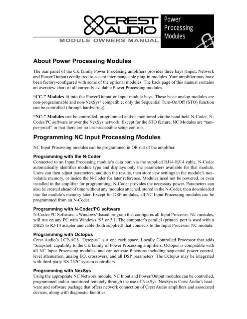
MODULE OWNERS MANUAL<br />
<strong>About</strong> <strong>Power</strong> <strong>Processing</strong> <strong>Modules</strong><br />
<strong>Power</strong><br />
<strong>Processing</strong><br />
<strong>Modules</strong><br />
The rear panel of the CK family <strong>Power</strong> <strong>Processing</strong> amplifiers provides three bays (Input, Network<br />
and <strong>Power</strong>/Output) configured to accept interchangeable plug-in modules. Your amplifier may have<br />
been factory-configured with some of the optional modules. The back page of this manual contains<br />
an overview chart of all currently available <strong>Power</strong> <strong>Processing</strong> modules.<br />
“CC-” <strong>Modules</strong> fit into the <strong>Power</strong>/Output or Input module bays. These basic analog modules are<br />
non-programmable and non-NexSys ® compatible; only the Sequential Turn-On/Off (STO) function<br />
can be controlled (through hardwiring).<br />
“NC-” <strong>Modules</strong> can be controlled, programmed and/or monitored via the hand-held N-Coder, N-<br />
Coder/PC software or over the NexSys network. Except for the STO feature, NC <strong>Modules</strong> are “tamper-proof”<br />
in that there are no user-accessible setup controls.<br />
Programming NC Input <strong>Processing</strong> <strong>Modules</strong><br />
NC Input <strong>Processing</strong> modules can be programmed in OR out of the amplifier.<br />
Programming with the N-Coder<br />
Connected to an Input <strong>Processing</strong> module’s data port via the supplied RJ14-RJ14 cable, N-Coder<br />
automatically identifies module type and displays only the parameters available for that module.<br />
Users can then adjust parameters, audition the results, then store new settings in the module’s nonvolatile<br />
memory, or inside the N-Coder for later reference. <strong>Modules</strong> need not be powered, or even<br />
installed in the amplifier for programming; N-Coder provides the necessary power. Parameters can<br />
also be created ahead of time without any modules attached, stored in the N-Coder, then downloaded<br />
into the module’s memory later. Except for DSP modules, all NC Input <strong>Processing</strong> modules can be<br />
programmed from an N-Coder.<br />
Programming with N-Coder/PC software<br />
N-Coder/PC Software, a Windows ® -based program that configures all Input Processor NC modules,<br />
will run on any PC with Windows ‘95 or 3.1. The computer’s parallel (printer) port is used with a<br />
DB25 to RJ-14 adapter and cable (both supplied) that connects to the Input Processor NC module.<br />
Programming with Octopus<br />
<strong>Crest</strong> <strong>Audio</strong>’s LCP-AC8 “Octopus” is a one rack space, Locally Controlled Processor that adds<br />
‘Snapshot’ capability to the CK family of <strong>Power</strong> <strong>Processing</strong> amplifiers. Octopus is compatible with<br />
all NC Input <strong>Processing</strong> modules, and can activate functions including sequential power control,<br />
level attenuation, analog EQ, crossovers, and all DSP parameters. The Octopus may be integrated<br />
with third-party RS-232C system controllers.<br />
Programming with NexSys<br />
Using the appropriate NC Network module, NC Input and <strong>Power</strong>/Output modules can be controlled,<br />
programmed and/or monitored remotely through the use of NexSys. NexSys is <strong>Crest</strong> <strong>Audio</strong>’s hardware<br />
and software package that offers network connection of <strong>Crest</strong> <strong>Audio</strong> amplifiers and associated<br />
devices, along with diagnostic facilities.
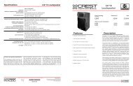
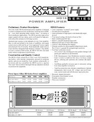
Input <strong>Processing</strong> Module Connections<br />
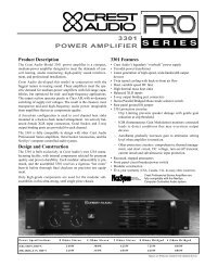
The CK family of amplifiers come standard with a CC-IPB Input module. Barrier strip input connectors<br />
and removable individual channel rotary attenuators are provided. All Input modules have<br />
an internal voltage gain/input sensitivity jumper that is factory-set for X40 gain.<br />
Input barrier strip lug / gauge information<br />
Input barrier strips have a 0.325" (8.3mm) center and 0.270" (6.9mm) lug space. For connecting to<br />
the input barrier strips, a wire gauge between 14 AWG (2.5mm 2 ) & 24 AWG (0.25mm 2 ), and spade<br />
lugs (Panduit Part No. PNF 18-6LF-C or equivalent) are recommended.<br />
SEE INSTRUCTION MANUAL<br />
Input A Input B<br />
+ – + –<br />
Input Barrier Strip<br />
Level<br />
A 3<br />
2<br />
1<br />
0<br />
Level<br />
B 3<br />
2<br />
1<br />
0<br />
Model<br />
CC-IPB<br />
Balanced vs. unbalanced inputs<br />
Barrier strip inputs are ready to accept balanced signals.<br />
For use with an unbalanced source, tie the<br />
inverting (minus) input to ground by installing a<br />
jumper across the appropriate barrier strip terminals.<br />
If the inverting input is left floating, a 6 dB loss in<br />
gain will result.<br />
AES/EBU Input<br />
This XLR jack accepts a standard AES/EBU XLR<br />
plug.<br />
Daisy chaining<br />
Some Input <strong>Processing</strong> modules have daisy-chained outputs, located on barrier strip terminals.<br />
NC-AES and NC-DSP-D modules have balanced daisy chain outputs.<br />
NC-DSP-A and NC-SEQ modules have unbalanced daisy chain outputs.<br />
NC-MCO and NC-MEQ modules have unbalanced mono HP/LP daisy chain outputs.<br />
The NC-SCO module has unbalanced stereo HP/LP daisy chain outputs.<br />
NC-IPE page input & enable connections<br />
Get information from engineering<br />
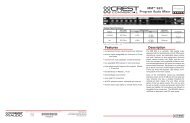
Input <strong>Processing</strong> Module Attenuators<br />
Operation<br />
Channel attenuators (A&B) are used to control signal level. Ideally, the amplifier should be operated<br />
with the controls at 0dB attenuation. When the amplifier is being used in bridged mono mode,<br />
both attenuators must at the same level.<br />
Knob Removal<br />
The attenuator knobs can be removed and replaced with blanking plugs.<br />
The procedure for attenuator knob removal is as follows:<br />
4 5<br />
6<br />
4 5<br />
6<br />
7<br />
8<br />
9<br />
10<br />
7<br />
8<br />
9<br />
10<br />
Input Level<br />
Attenuators<br />
1. With an X-Acto or similar knife, pop off the grey key cap of the attenuator knob. This will reveal<br />
the inside nut.<br />
2. Using needle nose pliers or appropriate size nut driver, loosen and remove the inside nut.<br />
3. Slide the attenuator knob off the shaft.<br />
4. Insert a regular screwdriver in the slotted end of the shaft, and adjust attenuation to desired level.<br />
5. Blanking plugs may now be inserted in the attenuator holes.
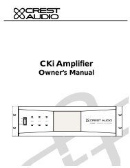
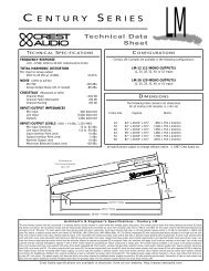
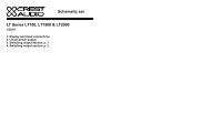
Input <strong>Processing</strong> <strong>Modules</strong> - Internal Options<br />
Input sensitivity/voltage gain jumper<br />
Input modules have user-settable jumpers to configure Input Gain/Sensitivity. These internal<br />
jumpers (two for CC-IPB, three for all input NC modules), labeled “W1 W2 W3”, are used to set<br />
the overall gain of the amplifier.<br />
+26dB<br />
0dBu<br />
+32dB<br />
W1<br />
W2<br />
+26dB<br />
+26dB<br />
0dBu<br />
+32dB<br />
0dBu IN<br />
+32dB<br />
Input Gain/Sensitivity Jumpers<br />
A<br />
B<br />
+26dB<br />
0dBu<br />
+32dB<br />
.775V / 0 dBu (For Full <strong>Power</strong>) X20 (+26 dB)<br />
NexSys/N-Coder jumper<br />
The 3 positions (shown at left) allow<br />
the amplifier to be set for constant gain<br />
of X20 (26 dB), X40 (32 dB), OR constant<br />
sensitivity for full output (.775V)<br />
at 0 dBu input. The standard factory<br />
setting is for X40 (32dB). All jumpers<br />
must be set to the same position as<br />
shown.<br />
To change jumper settings, the Input<br />
module must first be removed from the<br />
amplifier.<br />
Warning! Amplifier must<br />
be removed from AC<br />
mains supply before this<br />
operation is undertaken!<br />
The diagram at left shows the location<br />
of these jumpers on the CC-IPB module.<br />
The diagram at the lower right<br />
shows the location of the jumpers on<br />
the NC-IPN module.<br />
All NC <strong>Modules</strong> have internal jumpers used to set the module for operation with NexSys or N-<br />
Coder. These jumpers are labeled “W4 W5” on the Input module circuit board.<br />
N-CODE<br />
NC-NXS N-CODE<br />
NC-NXS<br />
N-Coder Setup NexSys Setup<br />
The “NC-NXS” jumper position<br />
allows operation with NexSys,<br />
while the “NCODE” jumper posi-<br />
Channel A Jumper<br />
Channel B Jumper<br />
NexSys Indicator Jumper (NC-IPN Only)<br />
+26dB<br />
0dBu<br />
+32dB<br />
+26dB<br />
0dBu<br />
+32dB<br />
CREST AUDIO<br />
2 6 C 2 7 9 7 - 0 2<br />
+26dB<br />
0dBu<br />
+32dB<br />
X40 (+32dB) Standard Factory Setting<br />
W2 W1 W3<br />
+26dB<br />
0dBu Sen<br />
+32dB<br />
Input Gain/Sensitivity Jumpers<br />
Nexsys / N-Coder Jumpers<br />
tion permits the Input module to be programmed through N-Coder or N-Coder/PC software when<br />
the amplifier is off.<br />
Note: Factory setting is the ‘NexSys’ position. If NexSys, N-Coder, or N-Coder/PC software is not<br />
being used, jumper position will have no effect upon the operation of the amplifier.<br />
CREST AUDIO<br />
2 6 C 2 1 9 7 - 0 2<br />
W4 W5<br />
N-CODE<br />
NC-NXS
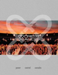
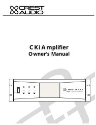
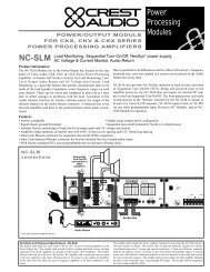
Swapping out <strong>Modules</strong><br />
Only jumper setting changes or module upgrades require modules to be removed from the amplifier.<br />
Contact <strong>Crest</strong> <strong>Audio</strong> Customer Service for full details on module removal. The ‘General Module<br />
Setup’ diagram indicates the general setup of the rear panel module/bay configuration.<br />
If Load Monitoring is<br />
employed, an additional ribbon<br />
cable will be located here.<br />
CLASS 2 WIRING<br />
MAY BE USED<br />
Output<br />
–<br />
A<br />
+<br />
+<br />
B<br />
–<br />
Signal<br />
Ground<br />
Lift<br />
Jumper<br />
Designed & manufactured in the USA by:<br />
Model<br />
Name<br />
CKV 100<br />
CKV 200<br />
CKV 400<br />
CKV 800<br />
CKV 1600<br />
CKV 2400<br />
Network<br />
Output <strong>Power</strong><br />
@70.7V<br />
50W<br />
100W<br />
200W<br />
400W<br />
800W<br />
1200W<br />
+ – + –<br />
Data<br />
Ribbon Cable from<br />
Network Module, if fitted<br />
Network Module<br />
<strong>Crest</strong> <strong>Audio</strong> Inc.<br />
100 Eisenhower Dr.<br />
Paramus, New Jersey 07652 USA<br />
Model<br />
Name<br />
CKS 100<br />
CKS 200<br />
CKS 400<br />
CKS 800<br />
CKS 800-2<br />
CKS 1200-2<br />
CKS 1600-2<br />
2<br />
3<br />
4<br />
5<br />
6<br />
Address<br />
0<br />
0<br />
1<br />
7<br />
Output <strong>Power</strong><br />
@8Ω/Ch.<br />
8<br />
F<br />
9<br />
Hi<br />
50W<br />
100W<br />
200W<br />
400W<br />
400W<br />
600W<br />
800W<br />
E<br />
D<br />
A<br />
C<br />
B<br />
2<br />
3<br />
4<br />
Designed & manufactured in the USA by:<br />
Model<br />
Name<br />
CKV 100<br />
CKV 200<br />
CKV 400<br />
CKV 800<br />
CKV 1600<br />
CKV 2400<br />
5<br />
6<br />
1<br />
7<br />
Network<br />
Output <strong>Power</strong><br />
@70.7V<br />
50W<br />
100W<br />
200W<br />
400W<br />
800W<br />
1200W<br />
+ – + –<br />
8<br />
F<br />
9<br />
Lo<br />
E<br />
D<br />
A<br />
C<br />
B<br />
Model<br />
NC-NXS<br />
Data<br />
<strong>Crest</strong> <strong>Audio</strong> Inc.<br />
100 Eisenhower Dr.<br />
Paramus, New Jersey 07652 USA<br />
Model<br />
Name<br />
CKS 100<br />
CKS 200<br />
CKS 400<br />
CKS 800<br />
CKS 800-2<br />
CKS 1200-2<br />
CKS 1600-2<br />
2<br />
3<br />
4<br />
5<br />
6<br />
1<br />
7<br />
Output <strong>Power</strong><br />
@8Ω/Ch.<br />
0<br />
8<br />
Hi<br />
50W<br />
100W<br />
200W<br />
400W<br />
400W<br />
600W<br />
800W<br />
Address<br />
F<br />
9<br />
E<br />
D<br />
A<br />
C<br />
B<br />
2<br />
3<br />
4<br />
5<br />
6<br />
N-Coder<br />
Data<br />
Port<br />
1<br />
7<br />
0<br />
8<br />
F<br />
9<br />
Lo<br />
E<br />
D<br />
A<br />
C<br />
B<br />
Model<br />
NC-NXS<br />
SEE INSTRUCTION MANUAL<br />
Input A Input B<br />
+ – + –<br />
PUSH<br />
N-Coder<br />
Data<br />
Port<br />
Error<br />
AES/EBU<br />
In<br />
SEE INSTR<br />
Level 4 5<br />
6<br />
A 3 7<br />
2<br />
8<br />
1<br />
9<br />
0 10<br />
Level 4 5<br />
6<br />
B 3 7<br />
2<br />
8<br />
1<br />
9<br />
0 10<br />
Model<br />
NC-IPN<br />
Input Module<br />
Required Tools<br />
A Phillips screw driver. Should the<br />
module jumpers need to be changed<br />
or removed, a pair of long nose or<br />
needle nose pliers is also useful.<br />
Precautions<br />
Amplifier is shown with the top<br />
cut away for clarity only. Dangerous<br />
voltages exist inside, and only a <strong>Crest</strong><br />
<strong>Audio</strong>-certified service technician<br />
should remove the top cover!<br />
Removable modules contain staticsensitive<br />
devices; handle modules at<br />
static-safe work stations! The amplifier<br />
MUST be switched off and the<br />
mains plug removed from the supply<br />
before module removal operation is<br />
undertaken.<br />
Removing or Replacing an Input Module.<br />
Remove the four #8 3/8" Phillips pan head sheet<br />
metal screws that secure the module to the chassis.<br />
The module is connected electrically to the<br />
amplifier via multi-pin ribbon cables. Unplugging<br />
the module from the ribbon cable connectors<br />
frees the module for removal. To insert the same<br />
or another module, simply reverse this procedure,<br />
making sure that any ribbon cable connectors are<br />
properly and securely seated. Note: The amplifier<br />
must not be operated without an Input module in<br />
place.<br />
Removing or Replacing a Network Module.<br />
This process is the same as that for removing/replacing an<br />
Input module. Be aware, though, that if an NC-NXS<br />
Network module is being removed or replaced, four multipin<br />
ribbon cables will need to be disconnected. Note:<br />
Standard CK family amplifiers come with a blank panel<br />
installed in the Network bay. The amplifier must not be operated<br />
without a Network module or blank panel in place.<br />
DO NOT attempt to replace or remove a <strong>Power</strong>/Output Module. This module can only<br />
be serviced by a <strong>Crest</strong> <strong>Audio</strong> certified service technician. Please consult your dealer,<br />
<strong>Crest</strong> <strong>Audio</strong> representative, or <strong>Crest</strong> <strong>Audio</strong> Customer Service for assistance.<br />
User-inflicted damage to this module will invalidate your warranty.
Storing Unused <strong>Modules</strong><br />
<strong>Power</strong> <strong>Processing</strong> modules contain static-sensitive devices; therefore<br />
unused modules must be stored in a static-safe environment, preferably at<br />
normal room temperature!<br />
Network Module Information<br />
The CC-BLK (blank panel) comes standard with all amplifiers.<br />
When a Network module (NC-NXS) is installed in this bay, network connection is made via a pair<br />
of three-pin Phoenix-type connectors. They are wired in parallel, and form a loop-through connection.<br />
(Mates for these connectors are shipped with the Network module.) Network bus addressing is<br />
accomplished through use of the Hi and Lo Address dials. See the NexSys Software manual for more<br />
information on NexSys bus connection and configuration.<br />
<strong>Power</strong>/Output Module Speaker Connections<br />
Speakers are connected using the Output Barrier Strip connectors. Spade lugs, ring tongues or bare<br />
wire may be connected to the output barrier strip elements. Spade Lug measurements for Output<br />
barrier strip are as follows: .44" (11mm) screw spacing, .32" (8mm) lug space. For output spade<br />
lugs, Panduit Part No. PNF 14-8LF-C (or equivalent) is recommended. Make sure the amplifier is<br />
turned off before you change any output connections or jumpers. Also ensure that the load impedance<br />
being connected is not less than the amplifier's ability to drive it. See the CK family <strong>Power</strong><br />
<strong>Processing</strong> Amplifier Manual for more information on speaker connection.<br />
Service Information<br />
For service, contact your nearest <strong>Crest</strong> <strong>Audio</strong> Service Center, Distributor, Dealer, or <strong>Crest</strong> <strong>Audio</strong> Inc.<br />
Customer Service directly at: Tel. 201.909.8700 (USA) Fax. 201.909.8744 (USA). For technical<br />
inquiries only, the <strong>Crest</strong> <strong>Audio</strong> Technical Services Dept. can be faxed at 201.587.0550 (USA). <strong>Crest</strong><br />
<strong>Audio</strong> may also be contacted on the World Wide Web at: http://www.crestaudio.com.
Sequential Turn-On/Off Connections<br />
CK family amplifiers come standard with the CC-STL Sequential Turn-On/Turn-Off (STO)<br />
Output/<strong>Power</strong> module installed. On this module, a four-pin Sequential Turn-On/Turn-Off (STO)<br />
connector is supplied. A mating connector is shipped with the amplifier. With the amplifier front<br />
power switch set to “remote”, a voltage of between +8 to +18 VDC can be applied across the “Com”<br />
and “+8 to +18V” terminals. When the voltage is on/available, a closure between the “In” and<br />
“Com” terminals will turn the amplifier on. Additional amplifiers are added to the turn-on chain by<br />
looping from the “Out” terminal of one amplifier into the “In” terminal of the next amplifier.<br />
Standard Sequential Turn-On/Turn-Off.<br />
For CK family amplifier systems configured for basic non-NexSys applications, (CC-IPB with CC-<br />
STL) an external power supply is needed to provide a nominal +8 to +18 Volts to each STL module.<br />
The number of CC-STL modules that an external DC supply will be able to power is dependent<br />
on the power supply’s voltage output and current capability. <strong>Crest</strong> <strong>Audio</strong>’s external Direct Plug-In<br />
<strong>Power</strong> Supply Unit (CC-WW1) supplies 9 volts at 300 milliamps and can power 15 CC-STL modules.<br />
Use only a two-wire power supply! If your configuration requires the STO control of more than<br />
15 amplifiers, contact <strong>Crest</strong> <strong>Audio</strong> Customer Service for more information. (Note that module CC-<br />
SDC has an integral STO power supply, and does not require CC-WW1).<br />
The “Com” and “+8 to+18V” terminals on each CK family amplifier are bussed together in parallel<br />
and connected to the DC supply. The “Out” terminal of each CK amplifier is connected to the “In”<br />
terminal of the next CK amplifier<br />
Standard Sequential<br />
Turn-On/Off<br />
(max. # of amplifiers is<br />
15 per CC-WW1)<br />
LISTED 8B42<br />
COMMERCIAL<br />
POWER<br />
AMPLIFIER<br />
120V~60 Hz 15A<br />
LISTED 8B42<br />
COMMERCIAL<br />
POWER<br />
AMPLIFIER<br />
120V~60 Hz 15A<br />
In<br />
Out<br />
Com<br />
+8 to 18VDC<br />
20 mA<br />
NEC<br />
CLASS 2 ONLY<br />
In<br />
Out<br />
Com<br />
+8 to 18VDC<br />
20 mA<br />
NEC<br />
CLASS 2 ONLY<br />
CC-WW1<br />
Direct Plug-In<br />
<strong>Power</strong> Supply Unit<br />
+8 (min) to +18VDC (max)<br />
in the turn-on sequence. The first<br />
amplifier in the chain requires an<br />
SPST closure between it’s “In”<br />
terminal and “Com” terminal to<br />
initiate the power turn-on<br />
sequence and keep the amplifiers<br />
in the chain powered on.<br />
Turn-on delay time between<br />
amplifiers fitted with basic modules<br />
(i.e., CC-STL) is approximately<br />
100ms, turn-off delay time<br />
is 200ms.
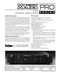
Manual or NexSys-Compatible Sequential Turn-On/Turn-Off.<br />
CK family amplifiers fitted with a NexSys-compatible NC <strong>Power</strong>/Output Module (NC-STI, NC-<br />
SAC, NC-SLM) may be powered up via NexSys OR with a manual switch closure. If NexSys is<br />
employed, the STO delay time is also software-controllable.<br />
Note: when using NexSys control, hard-wiring for manual switch closure between amplifiers<br />
should be used cautiously. If the switch closure output is wired up, it WILL cause the<br />
next amp to switch, regardless of which source (hardware switch or NexSys STO) has initiated<br />
the command.<br />
The modules (and the non-NexSys compatible CC-SIO) feature a 6-pin connector providing a 3wire<br />
input from switch closures (or from a CK family amplifier) and an opto-isolated 3-wire output<br />
to another CK amplifier. The 3-wire signals are: ON, OFF, and COM. To initiate either the ON or<br />
OFF function manually, simply provide a closure from the proper signal line to COM; after a time<br />
delay of approximately 200ms, the closure is echoed on the 3 isolated output signal pins to initiate<br />
the turn-on function in ‘downstream’ amplifiers. The on/off closures can be either momentary or<br />
constant contact.<br />
Manually Initiated (hard-wired) Sequential<br />
Turn-On/Off using NexSys-compatible<br />
<strong>Power</strong>/Output <strong>Modules</strong><br />
In<br />
On<br />
Com<br />
Off<br />
On<br />
Com<br />
Off<br />
Out<br />
In<br />
On<br />
Com<br />
Off<br />
On<br />
Com<br />
Off<br />
Out<br />
Output<br />
Output<br />
On<br />
Off<br />
NexSys-Initiated Sequential Turn-On/Off<br />
using NexSys-compatible <strong>Power</strong>/ Output<br />
<strong>Modules</strong> (unlimited # of amplifiers)<br />
PC<br />
®<br />
NC-NXS<br />
NC-NXS
A-AES/EBU B-Barrier Strip 4P-Four Pin 6P-Six Pin<br />
BS-Balanced, Stereo UBS=Unbalanced, Stereo MXO=Unbalanced Mono Crossover SXO-Unbalanced Stereo Crossover<br />
v. 1.1 11/6/97<br />
<strong>Power</strong>/Output <strong>Modules</strong> NexSys-Compatible STO Connection Self-powered Advanced NexSys functions<br />
CC-SDC N 4P N<br />
CC-SIO N 6P Y<br />
CC-STL N 4P N<br />
NC-SAC Y 6P Y Voltage/Current Monitor<br />
NC-SLM Y 6P Y Volt./Curr. & Load Monitor, <strong>Audio</strong> Return<br />
NC-STI Y 6P Y<br />
NexSys Twisted Pair Data Computer Sequential<br />
Network <strong>Modules</strong> Control Bus Connection Turn-On/Off Control<br />
NC-NXS Y Y Y<br />
A3300044<br />
Input <strong>Processing</strong> <strong>Modules</strong> Input Connection Daisy Chain Out Programmable Module Functions<br />
CC-IPB B N/A N Gain Control<br />
NC-AES A BS Y Gain Control<br />
NC-DSP-A B UBS Y Analog Input DSP<br />
NC-DSP-D A BS Y Digital Input DSP<br />
NC-IPE B N/A Y Gain Control, Priority Page<br />
NC-IPN B N/A Y Gain Control<br />
NC-MCO B MXO Y Gain Control, 2-way Xover<br />
NC-MEQ B MXO Y Gain Control, Mono EQ/2-way Xover<br />
NC-SCO B SXO Y Gain Control, Stereo Xover<br />
NC-SEQ B UBS Y Gain Control, Stereo EQ<br />
<strong>Power</strong> <strong>Processing</strong> <strong>Modules</strong> - Overview<br />
<strong>Crest</strong> <strong>Audio</strong> reserves the right to make improvements in manufacturing or design which may affect specifications.<br />
<strong>Crest</strong> <strong>Audio</strong> specification literature is available in downloadable PDF file format; visit our website at<br />
http://www.crestaudio.com. NexSys is a registered trademark of <strong>Crest</strong> <strong>Audio</strong> Inc. ©1997 <strong>Crest</strong> <strong>Audio</strong> Inc.<br />
<strong>Crest</strong> <strong>Audio</strong> Inc.<br />
100 Eisenhower Dr., Paramus NJ 07652 USA<br />
TEL: 201.909.8700 FAX: 201.909.8744<br />
http://www.crestaudio.com<br />
Printed in USA