Echotrac CV100 Manual - Communication Technology
Echotrac CV100 Manual - Communication Technology
Echotrac CV100 Manual - Communication Technology

Create successful ePaper yourself
Turn your PDF publications into a flip-book with our unique Google optimized e-Paper software.
ECHOTRAC <strong>CV100</strong><br />
USER MANUAL<br />
Version: 4.00<br />
Odom Hydrographic Systems, Inc.<br />
1450 Seaboard Avenue<br />
Baton Rouge, Louisiana<br />
USA<br />
70810-6261<br />
Telephone: (225) 769-3051 Fax: (225) 766-5122<br />
Email@Odomhydrographic.com<br />
http://www.odomhydrographic.com<br />
Number of pages: 69<br />
Date: February 19, 2008
<strong>Echotrac</strong> <strong>CV100</strong><br />
User <strong>Manual</strong><br />
Revision History<br />
Version Date Author Remarks<br />
3.28 12-12-2006 S. Apsey Initial version - Draft<br />
3.28 01-10-2007 P. Oostenrijk Updated for release<br />
3.29 05-22-2007 P. Oostenrijk Added description for Missed Returns on Setup tab.<br />
Minor change in Grey Shades description. Updated<br />
COM port's baudrate options to include 38400.<br />
Removed chapter Overview Parameters and Settings.<br />
This is now refers to the Technical Specification<br />
Ethernet Interface document.<br />
4.00 02-19-2008 P. Oostenrijk Updated Odom Title and Logo on cover page.<br />
Updated Header and Footer according to new<br />
template.<br />
Updated the introduction section and listed major<br />
changes.<br />
Inserted screen capture of new dialog for selecting a<br />
sounders on the network.<br />
Added Channel signal types and Bandwidth on System<br />
Tab.<br />
Update the NMEA serial output string formats.<br />
Updated uploading firmware and upgrading DSP<br />
firmware.<br />
© ODOM HYDROGRAPHIC SYSTEMS, INC. 2008<br />
All rights are reserved. Reproduction in whole or in part is prohibited without the prior written consent of the copyright<br />
owner.<br />
The information presented in this document does not form part of any quotation or contract, is believed to be<br />
accurate and reliable and may be subject to change without notice. The publisher will not accept any liability for<br />
any consequence of its use. Publication thereof does not convey nor imply any license under patent- or other<br />
industrial or intellectual property rights.<br />
Page 2 of 69<br />
Odom Hydrographic Systems, Inc. February 19, 2008
<strong>Echotrac</strong> <strong>CV100</strong><br />
User <strong>Manual</strong><br />
CONTENTS<br />
1 Introduction...................................................................................................................................................... 7<br />
1.1 Purpose....................................................................................................................................................... 8<br />
1.2 Scope .......................................................................................................................................................... 8<br />
1.3 Glossary ...................................................................................................................................................... 8<br />
1.4 References.................................................................................................................................................. 8<br />
2 Product description......................................................................................................................................... 9<br />
2.1 Specifications .............................................................................................................................................. 9<br />
2.2 Overview ................................................................................................................................................... 10<br />
2.3 Cabling ...................................................................................................................................................... 10<br />
2.4 Power connector ....................................................................................................................................... 10<br />
2.5 Choice of operating frequencies ............................................................................................................... 11<br />
2.6 Signal connector Transducer .................................................................................................................... 11<br />
2.7 Serial Ports................................................................................................................................................ 12<br />
2.8 LAN ........................................................................................................................................................... 12<br />
2.9 Power button ............................................................................................................................................. 12<br />
2.9.1 Power-OFF ........................................................................................................................................ 12<br />
2.9.2 Power-ON .......................................................................................................................................... 12<br />
2.9.3 STANDBY .......................................................................................................................................... 12<br />
2.10 Power indicator...................................................................................................................................... 12<br />
2.11 Ethernet indicators................................................................................................................................. 13<br />
2.12 Transmit indicators ................................................................................................................................ 13<br />
3 Installation...................................................................................................................................................... 14<br />
3.1 Software installation .................................................................................................................................. 14<br />
3.2 Setting up the equipment .......................................................................................................................... 14<br />
3.3 Powering up the equipment ...................................................................................................................... 15<br />
3.4 Transducer installation .............................................................................................................................. 16<br />
3.4.1 “THROUGH HULL” transducer installation........................................................................................ 16<br />
3.4.2 "SEA CHEST" transducer installation................................................................................................ 17<br />
3.4.3 "OVER-THE-SIDE" transducer installation ........................................................................................ 18<br />
4 <strong>Echotrac</strong> Control Program............................................................................................................................ 19<br />
4.1 Introduction:............................................................................................................................................... 19<br />
4.2 Important preparation information............................................................................................................. 19<br />
4.3 Starting the Application: ............................................................................................................................ 20<br />
4.4 Basic functionality ..................................................................................................................................... 27<br />
4.4.1 Real-time / Simulator mode (currently not supported)....................................................................... 27<br />
4.4.2 Menu structure ................................................................................................................................... 27<br />
4.4.3 <strong>Echotrac</strong> control program operation .................................................................................................. 29<br />
4.4.3.1 Setting up <strong>Communication</strong> ......................................................................................................... 29<br />
4.4.3.2 Enable/Disable <strong>Communication</strong> ................................................................................................. 29<br />
4.4.3.3 Standby mode............................................................................................................................. 29<br />
4.4.3.4 Standby-Bit ................................................................................................................................. 29<br />
4.4.3.5 Transmit Power........................................................................................................................... 30<br />
4.4.3.6 Receive Gain .............................................................................................................................. 30<br />
4.4.3.7 Alarm........................................................................................................................................... 30<br />
4.4.4 SYSTEM tab ...................................................................................................................................... 31<br />
4.4.4.1 Units............................................................................................................................................ 31<br />
4.4.4.2 Channel ...................................................................................................................................... 31<br />
4.4.4.3 Echo Alarm ................................................................................................................................. 31<br />
Page 3 of 69<br />
Odom Hydrographic Systems, Inc. February 19, 2008
<strong>Echotrac</strong> <strong>CV100</strong><br />
User <strong>Manual</strong><br />
4.4.4.4 Trigger (optional support) ........................................................................................................... 31<br />
4.4.4.5 Ping rate ..................................................................................................................................... 31<br />
4.4.4.6 Maximum depth (Range) ............................................................................................................ 31<br />
4.4.4.7 Blanking ...................................................................................................................................... 32<br />
4.4.4.8 Min. Depth Alarm ........................................................................................................................ 32<br />
4.4.4.9 Language.................................................................................................................................... 32<br />
4.4.4.10 Signal type.................................................................................................................................. 32<br />
4.4.4.11 Bandwidth................................................................................................................................... 32<br />
4.4.5 SETUP tab ......................................................................................................................................... 33<br />
4.4.5.1 Frequency................................................................................................................................... 33<br />
4.4.5.2 TX pulse width ............................................................................................................................ 33<br />
4.4.5.3 TVG curves................................................................................................................................. 33<br />
4.4.5.4 Threshold.................................................................................................................................... 33<br />
4.4.5.5 Min. Gate Width .......................................................................................................................... 33<br />
4.4.5.6 Skip Alarms................................................................................................................................. 34<br />
4.4.5.7 Subbottom Range....................................................................................................................... 34<br />
4.4.5.8 Subbottom TVG .......................................................................................................................... 34<br />
4.4.5.9 Pre Amp Gain ............................................................................................................................. 34<br />
4.4.5.10 Missed Returns .......................................................................................................................... 34<br />
4.4.5.11 Mode .......................................................................................................................................... 34<br />
4.4.6 CALIBRATE tab ................................................................................................................................. 35<br />
4.4.6.1 Draft ............................................................................................................................................ 35<br />
4.4.6.2 Index ........................................................................................................................................... 35<br />
4.4.6.3 Bar depth & Bar width................................................................................................................. 35<br />
4.4.6.4 Sound velocity ............................................................................................................................ 36<br />
4.4.7 CHART tab......................................................................................................................................... 37<br />
4.4.7.1 End-of-Scale & Scale Width ....................................................................................................... 37<br />
4.4.7.2 Scale Change ............................................................................................................................. 37<br />
4.4.7.3 Auto mark every n-seconds........................................................................................................ 38<br />
4.4.7.4 Digitizer Line ............................................................................................................................... 38<br />
4.4.7.5 Heave correction......................................................................................................................... 38<br />
4.4.7.6 Plot Gate..................................................................................................................................... 38<br />
4.4.8 COMMUNICATIONS tab ................................................................................................................... 39<br />
4.4.8.1 COM 1 Outputstring.................................................................................................................... 39<br />
4.4.8.2 COM 2 Remote Display.............................................................................................................. 39<br />
4.4.8.3 COM 3 GPS input selection........................................................................................................ 39<br />
4.4.8.4 COM 4 Heave input selection..................................................................................................... 39<br />
4.4.8.5 COM port Baud rates.................................................................................................................. 39<br />
4.4.9 DIAGNOSTIC tab............................................................................................................................... 39<br />
4.4.9.1 Simulator mode (currently not supported) .................................................................................. 39<br />
4.4.9.2 COM test (currently not supported) ............................................................................................ 39<br />
4.4.9.3 Version........................................................................................................................................ 39<br />
4.4.10 Menu options.................................................................................................................................. 40<br />
4.4.10.1 Load Settings (FILE) .................................................................................................................. 40<br />
4.4.10.2 Save Settings (FILE) .................................................................................................................. 40<br />
4.4.10.3 Load Port/IP settings (FILE)....................................................................................................... 40<br />
4.4.10.4 Save Port/IP settings (FILE)....................................................................................................... 40<br />
4.4.10.5 Exit (FILE) .................................................................................................................................. 40<br />
4.4.10.6 Open Connection (CONTROL) .................................................................................................. 40<br />
4.4.10.7 Close Connection (CONTROL).................................................................................................. 40<br />
4.4.10.8 Go to Standby (CONTROL) ....................................................................................................... 40<br />
4.4.10.9 ET startup loaded (CONTROL).................................................................................................. 40<br />
4.4.10.10 ET default settings (CONTROL) .............................................................................................. 41<br />
4.4.10.11 Depth monitor (CONTROL)...................................................................................................... 41<br />
Page 4 of 69<br />
Odom Hydrographic Systems, Inc. February 19, 2008
<strong>Echotrac</strong> <strong>CV100</strong><br />
User <strong>Manual</strong><br />
4.4.10.12 Set Time and Date (CONTROL) .............................................................................................. 41<br />
4.4.10.13 Dynamic scroll buttons (CONTROL)........................................................................................ 41<br />
4.4.10.14 Changing parameter values ..................................................................................................... 41<br />
4.4.10.15 Connection (INFO) ................................................................................................................... 42<br />
5 Operational procedures ................................................................................................................................ 43<br />
5.1 Things to consider when calibrating.......................................................................................................... 43<br />
5.2 How to calibrate the <strong>Echotrac</strong> CV ............................................................................................................. 43<br />
5.3 How to perform a bar check...................................................................................................................... 45<br />
5.4 Shallow Water Operation .......................................................................................................................... 46<br />
6 Troubleshooting ............................................................................................................................................ 47<br />
6.1 Problems installing the <strong>Echotrac</strong> CV Windows application....................................................................... 47<br />
6.2 How to copy the <strong>Echotrac</strong> CV windows installation files to disk ............................................................... 47<br />
6.3 The <strong>Echotrac</strong> CV does not seem to be working........................................................................................ 48<br />
6.4 The <strong>Echotrac</strong> CV power LED is off ........................................................................................................... 48<br />
6.5 The <strong>Echotrac</strong> CV power LED is flickering ................................................................................................. 48<br />
6.6 What are the COM-port settings ............................................................................................................... 48<br />
6.7 Known problems with Transducer............................................................................................................. 48<br />
7 Technical specifications............................................................................................................................... 49<br />
7.1 Computer communications ....................................................................................................................... 49<br />
7.2 Overview Serial Output string formats ...................................................................................................... 50<br />
7.3 Serial output strings .................................................................................................................................. 52<br />
7.3.1 <strong>Echotrac</strong> SBT..................................................................................................................................... 52<br />
7.3.2 <strong>Echotrac</strong> DBT..................................................................................................................................... 53<br />
7.3.3 Heave................................................................................................................................................. 55<br />
7.3.4 DESO25............................................................................................................................................. 56<br />
7.3.5 DESO DDV ........................................................................................................................................ 56<br />
7.3.6 DESO COMMANDS .......................................................................................................................... 57<br />
7.3.7 NMEA DBS ........................................................................................................................................ 57<br />
7.4 Serial Data input / Chart annotation.......................................................................................................... 58<br />
7.5 Serial heave input ..................................................................................................................................... 59<br />
7.6 External Serial Control of <strong>Echotrac</strong> Parameters ....................................................................................... 60<br />
8 Overview parameters and settings.............................................................................................................. 62<br />
8.1 External Ethernet Control of <strong>Echotrac</strong> Parameters................................................................................... 62<br />
9 Uploading Firmware ...................................................................................................................................... 63<br />
9.1 Upgrading Motorola Processor Firmware ................................................................................................. 63<br />
9.2 Upgrading DSP Firmware ......................................................................................................................... 64<br />
10 <strong>Echotrac</strong> CV Cable Connections.............................................................................................................. 65<br />
10.1 Serial 1................................................................................................................................................... 65<br />
10.2 Serial 2................................................................................................................................................... 65<br />
10.3 Serial 3................................................................................................................................................... 65<br />
10.4 Heave .................................................................................................................................................... 65<br />
10.5 LAN........................................................................................................................................................ 65<br />
10.6 Transducer............................................................................................................................................. 66<br />
10.7 DC.......................................................................................................................................................... 66<br />
Appendix A. CABLE CONNECTIONS: ................................................................................................................. 67<br />
Appendix B. Quick Start Operating Procedures ................................................................................................ 68<br />
Page 5 of 69<br />
Odom Hydrographic Systems, Inc. February 19, 2008
<strong>Echotrac</strong> <strong>CV100</strong><br />
User <strong>Manual</strong><br />
Page 6 of 69<br />
Odom Hydrographic Systems, Inc. February 19, 2008
<strong>Echotrac</strong> <strong>CV100</strong><br />
User <strong>Manual</strong><br />
1 INTRODUCTION<br />
There are four <strong>Echotrac</strong> CV units named <strong>Echotrac</strong> <strong>CV100</strong>, <strong>Echotrac</strong> CV200, <strong>Echotrac</strong> CV300 and <strong>Echotrac</strong> CVM<br />
(Mobile). This document covers the <strong>Echotrac</strong> <strong>CV100</strong> and will refer to this unit as “<strong>Echotrac</strong> CV”. This <strong>Echotrac</strong> CV<br />
supports one channel.<br />
The <strong>Echotrac</strong> CV is a hydrographic echo sounder design incorporating the cutting-edge technology, features and<br />
reliability of the <strong>Echotrac</strong> MKIII, plus the ease and flexibility of operation of a networked Windows® interface.<br />
The <strong>Echotrac</strong> CV transceiver units are supplied in a compact stand-alone package that is ideally suited to many<br />
shipboard installations. The <strong>Echotrac</strong> CV supports Chart-functionality in one optional format, a full size color LCD<br />
“electronic chart”. The “electronic chart” is supplied in flexible modular enclosures complete with swivel mounting<br />
hardware. A second option, that of operating the unit and collecting data on a networked PC, is also possible.<br />
The optional color LCD module offers internal data storage (in .XTF format) and playback of the analog return<br />
signal digitized to full 16-bit resolution. The <strong>Echotrac</strong> CV features a robust design and frequency agility enabling<br />
the operator to precisely match the transceiver to almost any existing transducer. Operator selectable TVG<br />
curves (10 Log, 20 Log, 30 Log, 40 Log, and Off) serve to optimise the <strong>Echotrac</strong> for shallow bottom detection<br />
tasks and for Sonar imaging. The <strong>Echotrac</strong> CV features unsurpassed interfacing flexibility, offering 4 serial ports<br />
that can be configured to interface with computers, positioning systems, motion reference units and remote<br />
displays. The <strong>Echotrac</strong> CV also has an Ethernet port that outputs the 16 bit samples of the acoustic data for<br />
further processing or visualization. The <strong>Echotrac</strong> CV also supports a number of output formats that are compatible<br />
with most common Echo Sounder strings.<br />
Figure 1: <strong>Echotrac</strong> <strong>CV100</strong><br />
To learn about the features of the <strong>Echotrac</strong> CV, this document is structured as a step by step manual; covering<br />
the <strong>Echotrac</strong> CV as a product, how to install the software and the equipment, how to use all the different control<br />
settings, how to perform certain procedures, how cables are wired to their connectors and troubleshooting.<br />
Some of the major changes as of version 4.00 are:<br />
- Replacement of the <strong>Echotrac</strong> Control Program with Odom eChart, a graphical data acquisition program.<br />
Because the <strong>Echotrac</strong> Control Program 4.00 will become obsolete, it does not support some of the major<br />
changes such as faster synchronization and adapting to the sounder’s hardware configuration.<br />
- Faster synchronization due to improved communication protocol.<br />
- Automatic detection of sounder(s) on the network and adapting to the sounder’s hardware configuration.<br />
Page 7 of 69<br />
Odom Hydrographic Systems, Inc. February 19, 2008
<strong>Echotrac</strong> <strong>CV100</strong><br />
User <strong>Manual</strong><br />
1.1 Purpose<br />
The purpose of this document is to explain the features and operation of the <strong>Echotrac</strong> CV.<br />
1.2 Scope<br />
The content of this document is focused on the end-user.<br />
1.3 Glossary<br />
DBS<br />
Depth Below Surface<br />
DBT<br />
Dual Bottom Tracking<br />
DGPS Differential Global Positioning System<br />
DSP<br />
Digital Signal Processor<br />
ETCV <strong>Echotrac</strong> CV<br />
NMEA National Marine Electronics Association<br />
SBT<br />
Single Bottom Tracking<br />
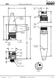
TNC<br />
Threaded Nut Connector<br />
TVG<br />
Time Varied Gain<br />
VDC<br />
Volts Direct Current<br />
1.4 References<br />
[1] Title: Windows Flash Utility: OdomFlash.exe<br />
Author(s): Patrick Oostenrijk<br />
Report no: N/A<br />
Version: 2.2<br />
Date: 2007-02-27<br />
[2] Title: Using <strong>Echotrac</strong> Ethernet Driver with Hypack<br />
Author(s): Stephen Apsey<br />
Report no: N/A<br />
Version: 1.0<br />
Date: 2006-07-17<br />
[3] Title: Technical Specification Ethernet Interface<br />
Author(s): Patrick Oostenrijk<br />
Report no: N/A<br />
Version: 1.3<br />
Date: 2007-05-22<br />
Page 8 of 69<br />
Odom Hydrographic Systems, Inc. February 19, 2008
<strong>Echotrac</strong> <strong>CV100</strong><br />
User <strong>Manual</strong><br />
2 PRODUCT DESCRIPTION<br />
2.1 Specifications<br />
Frequency<br />
• High Band: 100 kHz-750 kHz<br />
• Low Band: 24 kHz-50 kHz<br />
Output Power<br />
• Up to 200 watts RMS<br />
Input Power<br />
• 12 to 24 VDC 30 watts<br />
Resolution<br />
• 0.01m / 0.1 ft.<br />
Accuracy<br />
• 0.01m / 0.10 ft. +/- 0.1% of depth @<br />
200 kHz<br />
• 0.10m / 0.30 ft. +/- 0.1% of depth @<br />
33 kHz<br />
Depth Range<br />
• 0.2 – 600m / 0.5 – 600 ft.<br />
Chart Scales<br />
• 5,10,20,40,80,100,200,400,800m<br />
• 15,30,60,120,240,300,600,1200,<br />
2400ft.<br />
Phasing<br />
• Automatic scale change, 10%,20%,<br />
30% overlap or <strong>Manual</strong><br />
LCD Display<br />
• 15 inch TFT Screen<br />
• Sunlight Readable<br />
• Internal Data Storage in XTF format<br />
on 40GB Hard Disk<br />
• Data Transfer via Ethernet interface<br />
or USB Flash Drive<br />
Sound Velocity<br />
• 1370 – 1700 m/s<br />
• Resolution 1 m/s<br />
Transducer Draft Setting<br />
• 0 – 15m (0 – 50 ft.)<br />
Depth Display<br />
• On control PC and LCD display<br />
Clock<br />
• Internal battery backed time,<br />
elapsed time, and date clock<br />
Annotation<br />
• Internal – date, time, GPS position<br />
• External – from RS232 port<br />
Interfaces<br />
• 4 x RS232 and 1 x RS422 serial<br />
ports, baud rate selectable 4800-<br />
19200.<br />
• Inputs from external computer,<br />
motion sensor, sound velocity.<br />
• Outputs to external computer,<br />
remote display<br />
• Outputs with LCD chart – VGA<br />
video out<br />
• Ethernet interface<br />
• Heave – TSS1 and sounder<br />
sentence<br />
Blanking<br />
• 0 to full scale<br />
Installation<br />
• Desktop<br />
Software<br />
• <strong>Echotrac</strong> Control supplied<br />
• ChartView supplied with LCD<br />
configuration<br />
Environmental Operating Conditions<br />
• 0°– 50° C, 5 – 90% relative<br />
humidity, Non-condensing<br />
Dimensions<br />
• 28cm (11”) x 23cm (9”) W x<br />
11.5cm (4.5”) D<br />
Weight<br />
• 5 kg (11 lbs.)<br />
Options<br />
• Remote Display<br />
• Side Scan Transducer – single or<br />
dual channel side looking 200 kHz<br />
for 340kHz for search and<br />
reconnaissance<br />
Page 9 of 69<br />
Odom Hydrographic Systems, Inc. February 19, 2008
<strong>Echotrac</strong> <strong>CV100</strong><br />
User <strong>Manual</strong><br />
2.2 Overview<br />
On the backpanel of the <strong>Echotrac</strong> CV are all the connectors for serial communication interfacing, GPS data,<br />
Ethernet communication, Transducer signals and power. See below, in Figure 2 for an overview of all the<br />
connectors. Each item will be explained in more detail in the following chapters. The front panel has LED<br />
indicators for Ethernet communication, Transceiver board operation and power.<br />
Serial 1 Serial 3<br />
Transmit<br />
LED<br />
Power<br />
Button<br />
LAN<br />
Serial 2<br />
Heave<br />
Transducer<br />
12-24<br />
VDC<br />
Power<br />
LED<br />
LAN Status<br />
LED<br />
Figure 2: Overview of <strong>Echotrac</strong> CV<br />
The <strong>Echotrac</strong> CV is a flexible unit designed for tabletop. Rack mounting can be accommodated with the included<br />
special hardware. Where tabletop mounting is preferred, it is highly recommended that the unit be secured with<br />
external 'tie-downs' for rough seas or heavy swells.<br />
2.3 Cabling<br />
All cabling is via the connectors located in the recessed panel at the rear of the unit. A view of the connector<br />
arrangement is shown in Figure 2. Cable details are given in Appendix A. Care should be taken to route cables<br />
using horizontal and vertical runs wherever possible. Avoid paths that run adjacent to transmitter feeder cables or<br />
close to heat radiating elements such as steam pipes. For permanent installations, cables should be clamped at<br />
regular intervals (1m) along their complete lengths.<br />
2.4 Power connector<br />
The <strong>Echotrac</strong> CV can be powered by DC power sources. DC operation requires an input voltage between 11 and<br />
29 VDC (nominal 24 VDC). Average power consumption is approximately 25-30 watts. Frequently, power is<br />
derived from two 12 V lead-acid batteries connected in series. These batteries (24V configuration), fully charged,<br />
and in good condition, can normally power a unit for a full day without re-charging. Regulated DC supplies should<br />
be able to source a short duration in-rush current spike of approximately 6 amps and an average current load of 3<br />
amps. In the case of "charger" type (unregulated) supplies, the output should be "floated" across a battery load<br />
and not connected solely to the echo sounder’s DC input. Details of the power cable are given in Appendix A.<br />
Should the DC input voltage polarity be applied in reverse, an audible alarm within the unit will sound regardless<br />
of the POWER switch setting. In the event that the input voltage drops below the minimum threshold the unit will<br />
automatically shut down.<br />
Page 10 of 69<br />
Odom Hydrographic Systems, Inc. February 19, 2008
<strong>Echotrac</strong> <strong>CV100</strong><br />
User <strong>Manual</strong><br />
Setting up two batteries in series (24 Volts DC system)<br />
DC Power cable<br />
(-) (+)<br />
(-) (+)<br />
Battery 1<br />
12 Volts<br />
Jumper<br />
Battery 2<br />
12 Volts<br />
Using a jumper simply connect the positive post of battery 1 to the negative post on battery 2. Connect the<br />
negative lead from the power cable to the negative post on battery 1 and the positive lead to the positive post on<br />
battery 2. Always check the voltage with a voltage or multi-meter before connecting the DC power cable to any<br />
equipment. Make sure that all the connecting equipment is also turned off before applying the power cables.<br />
Otherwise the transients of such a ‘jump-start’ could damage the equipment.<br />
2.5 Choice of operating frequencies<br />
The <strong>Echotrac</strong> CV can be configured to use either a High or a Low frequency board, respectively 100 kHz – 750<br />
kHz or 24 kHz – 50 kHz. Standard transducers are generally available from stock that support the frequency<br />
ranges listed on the product description page (See 2.1 Specifications).<br />
2.6 Signal connector Transducer<br />
The signal from the transducer is passed to the <strong>Echotrac</strong> CV via a standard Odom transducer cable with a twistlock<br />
connector.<br />
Page 11 of 69<br />
Odom Hydrographic Systems, Inc. February 19, 2008
<strong>Echotrac</strong> <strong>CV100</strong><br />
User <strong>Manual</strong><br />
2.7 Serial Ports<br />
Serial 1<br />
The <strong>Echotrac</strong> CV uses Serial port 1 to output depth data. Using a special Flash Utility program, the port is also<br />
used to upgrade the software in the <strong>Echotrac</strong> CV. Another use of the port is to send commands to the <strong>Echotrac</strong><br />
CV or request certain parameter settings.<br />
Serial 2<br />
Serial port 2 is dedicated to connect the optional remote display to the <strong>Echotrac</strong> CV. The port can be configured<br />
to use either an RS232 or RS422 protocol.<br />
However, this feature is currently not supported with the <strong>Echotrac</strong> CV.<br />
Serial 3<br />
Serial port 3 is used to receive external GPS data in NMEA GLL or GGA format. It is best to only configure the<br />
GPS to output only one of these strings as too much data can interfere with the communication processor’s other<br />
tasks. When a GPS is connected to the <strong>Echotrac</strong> CV and is receiving position information, the <strong>Echotrac</strong> CV<br />
100can output that GPS information on the Ethernet port.<br />
Heave<br />
Serial port 4 is used to receive motion sensor data in TSS1 format (heave). This port enables the <strong>Echotrac</strong> CV to<br />
accept data from a motion compensator to apply corrections for the vertical movement caused by swells. The<br />
<strong>Echotrac</strong> CV will only correct the depth for Heave. No corrections are done for Roll and Pitch.<br />
2.8 LAN<br />
The LAN port is used by the <strong>Echotrac</strong> CV to send and receive data on the network. The <strong>Echotrac</strong> CV can be<br />
connected directly to a Hub or a Switch using a regular UTP CAT-5 ethernet cable. A regular cable is also known<br />
as a ‘straight’ UTP cable. When the <strong>Echotrac</strong> is connected directly to a computer, a so-called ‘cross-over’ UTP<br />
cable must be used. When a computer is directly connected to the <strong>Echotrac</strong> CV using a crossover cable, the<br />
operating system on the computer may take 2-3 minutes before the computer has accepted a valid IP address. To<br />
prevent this delay, you can assign the computer a static IP address or use a Hub/Switch.<br />
2.9 Power button<br />
The power switch in the ON position will power-up the internal circuitry. In the OFF position it will power-down the<br />
internal circuitry.<br />
2.9.1 Power-OFF<br />
The main power switching circuitry is open in this position.<br />
2.9.2 Power-ON<br />
On "power-up", the unit performs a Self-test to check system memory and also tests the Non-volatile RAM battery<br />
voltage. If there was a problem with the Non-volatile RAM, the factory defaults will be loaded. The unit then enters<br />
the sounding mode and begins data acquisition.<br />
2.9.3 STANDBY<br />
The main power circuitry is energized, drawing current from the mains and providing regulated DC voltages to all<br />
internal modules. The unit is no longer in the sounding mode when it is in the standby position. However, the<br />
Parameter Entry System is enabled.<br />
2.10 Power indicator<br />
When the <strong>Echotrac</strong> CV is turned on, a red LED will be on to indicate that the internal systems have powered up<br />
successfully. The red LED is located below the power button.<br />
Page 12 of 69<br />
Odom Hydrographic Systems, Inc. February 19, 2008
<strong>Echotrac</strong> <strong>CV100</strong><br />
User <strong>Manual</strong><br />
2.11 Ethernet indicators<br />
The TX indicator on the <strong>Echotrac</strong> CV indicates whether or not the data is transmitted on the Ethernet port. The<br />
frequency at which the TX indicator flickers also indicates whether the <strong>Echotrac</strong> CV is outputting data at a slow or<br />
fast pace.<br />
The Link indicator on the <strong>Echotrac</strong> CV indicates that it recognizes the presence of a network. If the receiving end<br />
of the ethernet cable is connected to a computer or a hub/switch that is not powered on, the link light will not be<br />
on.<br />
2.12 Transmit indicators<br />
The Transmit indicators on the <strong>Echotrac</strong> CV indicate whether the Transducer is firing or not. The frequency at<br />
which the Channel indicator flickers also indicates whether the Transducer is firing at a slow or fast pace.<br />
Page 13 of 69<br />
Odom Hydrographic Systems, Inc. February 19, 2008
<strong>Echotrac</strong> <strong>CV100</strong><br />
User <strong>Manual</strong><br />
3 INSTALLATION<br />
This section contains the information necessary to install the <strong>Echotrac</strong> Control Software, power-up and connect<br />
the <strong>Echotrac</strong> CV. The installation procedure consists of a number of steps. Each step corresponds to a specific<br />
chapter. It is recommended that these steps (chapter 3.1, 3.2 and 3.3) for the installation procedure be followed in<br />
this order. See also the quick start procedure in Appendix B.<br />
3.1 Software installation<br />
The minimum requirements for a personal computer to install and run only the <strong>Echotrac</strong> Control software are:<br />
• Windows 98<br />
• Pentium-I, running at 200 MHz<br />
• 32 Mb of internal memory<br />
• 10 Mb of free space on the harddrive<br />
• One COM-port<br />
The <strong>Echotrac</strong> control program is fully tested on the following Operating Systems:<br />
• Windows 98<br />
• Windows 2000<br />
• Windows XP<br />
• Windows NT<br />
Note: Windows ME is not supported.<br />
Note: A minimum of two COM-ports are needed to run: one port to receive serial data from the <strong>Echotrac</strong> and<br />
communicate with the <strong>Echotrac</strong>, and one port to receive GPS. This is an example of a situation when ethernet<br />
cannot be used.<br />
The software that is shipped with the unit can be installed on the personal computer by executing the program<br />
called SETUP.EXE. This program will install the <strong>Echotrac</strong> Control software in the Program Files directory. During<br />
the setup process it is possible that Windows will ask if you wish to keep certain files on the computer that are<br />
older or newer than the ones being installed. By default it is advised to keep the files that are currently on the<br />
computer to avoid any conflicts or problems with other programs. If during the setup process, the setup program<br />
cannot find the files on your computer that it needs to install the <strong>Echotrac</strong> CV, the missing file(s) will be copied<br />
onto the hard drive.<br />
3.2 Setting up the equipment<br />
The <strong>Echotrac</strong> CV is a lightweight unit designed for portability. An interconnection diagram is shown in Figure 3.<br />
Care should be taken to route cables using horizontal and vertical runs wherever possible. Avoid paths that run<br />
adjacent to transmitter feeder cables or close to heat radiating elements such as steam pipes. For permanent<br />
installations, cables should be clamped at regular intervals (3 feet or 1 meter) along their complete lengths.<br />
The <strong>Echotrac</strong> CV requires either an input voltage between: +11 and +29 VDC (standard). The unit consumes<br />
less than 30 watts of power in normal operation. Power is frequently derived from one or two 12 V lead-acid<br />
batteries. Two batteries (24V configuration), fully charged, and in good condition, can normally power a unit for a<br />
full day without re-charging. Details of the power cable are given in the chapter 2.4 Power connector and the<br />
Appendix .<br />
All cables are attached to the connectors located in the recessed area at the left rear of the unit (See Figure 2 in<br />
chapter 2.2). Connections are made through multi-pin “MS” style connectors, between the <strong>Echotrac</strong> CV, its power<br />
source, the transducer and all computer or peripheral devices.<br />
The following Interconnection block diagram shows everything that can be connected to the <strong>Echotrac</strong> CV. All<br />
these peripherals are not required to use the basic functionality of the <strong>Echotrac</strong> CV.<br />
Page 14 of 69<br />
Odom Hydrographic Systems, Inc. February 19, 2008
<strong>Echotrac</strong> <strong>CV100</strong><br />
User <strong>Manual</strong><br />
Motion Sensor (Heave)<br />
f<br />
ECHOTRAC<br />
<strong>CV100</strong><br />
g<br />
Remote Display (COM2)<br />
Optional External GPS (COM3)<br />
e<br />
a/d<br />
control (COM1)<br />
Computer<br />
Power<br />
c<br />
b<br />
Transducer<br />
Figure 3: Interconnection block diagram<br />
Before connecting any of the cables, make sure that the computer, the <strong>Echotrac</strong> CV and other peripherals are<br />
turned off. The list below is a sequence of steps for connecting the <strong>Echotrac</strong> CV with the computer and GPS. If<br />
any problems arise, see the Troubleshooting section.<br />
a) Connect the RS232 cable between the computer and the DB9 connector labeled “Serial 1”, if you need to<br />
collect depth data through the serial port or need to send command to the <strong>Echotrac</strong> CV.<br />
b) Connect the cable from the Transducer to the connector on the <strong>Echotrac</strong> CV labeled “Transducer”.<br />
c) Connect the power cable for the <strong>Echotrac</strong> CV to the connector labeled “POWER”.<br />
d) Connect the UTP ethernet cable to the LAN connector if you want to collect data across a network.<br />
If an external peripherals are used, then:<br />
e) Connect the RS232 cable between the connector labeled “Serial 3” and the external GPS.<br />
f) Connect the RS232 cable between the motion sensor and the connector labelled “Heave”.<br />
g) Connect the RS232 cable between the remote display and the connector labelled “Serial 2”.<br />
3.3 Powering up the equipment<br />
The following sequence must be followed when powering up the equipment:<br />
1. Turn on the personal computer.<br />
2. Turn on the <strong>Echotrac</strong> CV. After turning the Power Switch from the OFF position to ON, confirm that the power<br />
LED, Ethernet Link LED come on. After a few seconds, the Ethernet TX/RX LED and one or both of the<br />
Transmit High / Low LEDs should start blinking.<br />
3. Start the <strong>Echotrac</strong> CV Window Application program.<br />
4. Turn on optional peripherals such as GPS or motion sensor.<br />
5. Depending on water depth and bottom type, set the Tx Power to mid-range (position 6) in the <strong>Echotrac</strong> control<br />
program.<br />
6. Set the RxGAIN to about halfway on the maximum scale.<br />
7. Adjust RxGAIN and TxPOWER to get a clear strong record with few alarms on the displayed depth.<br />
Note: The <strong>Echotrac</strong> CV should always be turned on before running the <strong>Echotrac</strong> control program.<br />
Note: Should you feel that a return to the sounder’s default parameter values is called for, then select the Default<br />
Reset option in the <strong>Echotrac</strong> CV Window Application program.<br />
Page 15 of 69<br />
Odom Hydrographic Systems, Inc. February 19, 2008
<strong>Echotrac</strong> <strong>CV100</strong><br />
User <strong>Manual</strong><br />
3.4 Transducer installation<br />
Proper mounting of the transducer is a crucial part of the installation of any "survey" echo sounder. An improperly<br />
mounted transducer will result in poor system operation and unacceptable data quality.<br />
Important: See also chapter 6.7 Known problems with Transducer.<br />
In the case of temporary installations, the transducer is often mounted over-the-side. In permanent installations<br />
and "pay surveys," hull mounts are generally preferred and often required. In either case, the transducer should<br />
be mounted as far below the waterline as possible. In cases where "over the side" mounts are exposed to wave<br />
action, ensure that the transducer is mounted far enough below the surface so that it remains well submerged<br />
during vessel roll motions.<br />
A preferred mounting location is near the keel of the vessel, in an area where the planing attitude of the hull and<br />
the pitch and roll angles of the vessel have the least effect at operating speed. The transducer should be<br />
mounted far enough aft of the bow so that bubbles generated by the bow wave will not pass over the face of the<br />
unit. Transducers should be located away from sources of turbulence and cavitation bubbles such as propellers,<br />
bow thrusters and hull protrusions. Consideration should also be given to sources of mechanical noise generated<br />
within the vessel (engines, propellers, pumps, generators, etc.). In some severe cases of mechanically coupled<br />
noise, vibration-isolating mounts may be required to mechanically decouple the transducer from the hull.<br />
Transducer mounting can be accomplished in many different ways. The following three chapters show common<br />
configurations.<br />
3.4.1 “THROUGH HULL” transducer installation<br />
The top side of the transducer is accessible from inside the vessel while the transducer face is directly exposed to<br />
the water. Care should be taken to protect the transducer from damage and turbulence by installing a fairing with<br />
a sloping forward edge ahead of the unit. The fairing has the dual effect of both minimizing possible strike<br />
damage and smoothing the flow of water over the face of the transducer.<br />
Figure 4: Transducer mounted through the hull<br />
Page 16 of 69<br />
Odom Hydrographic Systems, Inc. February 19, 2008
<strong>Echotrac</strong> <strong>CV100</strong><br />
User <strong>Manual</strong><br />
3.4.2 "SEA CHEST" transducer installation<br />
In a "sea chest" mount, a fluid-filled enclosure large enough to contain the entire transducer is attached to the<br />
outer hull of the vessel. The outer hull is removed within the area of the chest and replaced with an acoustically<br />
clear "window" which is mounted flush with the hull surrounding the chest. Depending on construction, the<br />
material selected for the acoustic window, and the draft of the vessel, access can often be gained to the<br />
transducer from inside the hull without putting the vessel in dry-dock. In most installations, a water-filled<br />
standpipe is incorporated into the "sea chest" design in order to provide hydrostatic pressure equalization.<br />
Transducer cables generally leave these assemblies through stuffing tubes, which maintain the watertight integrity<br />
of the chest.<br />
Page 17 of 69<br />
Odom Hydrographic Systems, Inc. February 19, 2008
<strong>Echotrac</strong> <strong>CV100</strong><br />
User <strong>Manual</strong><br />
3.4.3 "OVER-THE-SIDE" transducer installation<br />
A mount of this type is frequently constructed from a length of pipe. This fixture should be sized to position the<br />
transducer well below the waterline and the pipe then fixed to a sturdy support on the vessel. Lines generally are<br />
attached at the transducer pipe and tied off fore and aft in order to maintain a stable, horizontal transducer<br />
attitude. Care should be taken to assure adequate protection for the transducer cable, particularly at the point<br />
where the cable leaves the transducer body.<br />
In all of the above installations, particular care should be taken to assure that the transducer radiating face<br />
remains as parallel to the water surface as much as possible while the vessel is moving.<br />
Page 18 of 69<br />
Odom Hydrographic Systems, Inc. February 19, 2008
<strong>Echotrac</strong> <strong>CV100</strong><br />
User <strong>Manual</strong><br />
4 ECHOTRAC CONTROL PROGRAM<br />
4.1 Introduction:<br />
This section contains the information necessary to operate the <strong>Echotrac</strong> CV using the <strong>Echotrac</strong> control program.<br />
The <strong>Echotrac</strong> control program is developed to provide the operator with complete control over the <strong>Echotrac</strong><br />
models.<br />
4.2 Important preparation information<br />
There are several gradations of preparation and this section will describe the bare minimum and a fully equipped<br />
survey preparation. Allow yourself at least one full day to setup and familiarize yourself with the equipment and<br />
software that you are going to use. This includes computers, GPS, motion sensors, transducers, network hubs<br />
and cables and third party programs.<br />
First, setup your computer and <strong>Echotrac</strong> CV in a comfortable environment to avoid troubleshooting out in the field.<br />
At this point you do not need any other equipment. If problems or questions should arise, access to the Internet<br />
and a land line (telephone) will be beneficial for Odom Hydrographic System engineers to provide good support.<br />
Follow the Quick Start operating procedures in Appendix B that basically instruct you to power on the <strong>Echotrac</strong><br />
CV, install the <strong>Echotrac</strong> Control program and communicate with the <strong>Echotrac</strong> CV.<br />
The <strong>Echotrac</strong> CV is shipped with a CD-ROM containing the latest version of software. There is a setup.exe that<br />
will install the control program for the <strong>Echotrac</strong> CV.<br />
Once the software is installed, connect all hardware including power to the echo sounder. Use the red Ethernet<br />
crossover cable supplied with your system purchase.<br />
Switch the <strong>Echotrac</strong> CV and computer power from OFF to ON.<br />
Confirm that the power LED and Ethernet Link LED on the unit come on. By factory default the <strong>Echotrac</strong> comes<br />
up in Standby and the <strong>Echotrac</strong> Control program is needed to start the echo-sounder. When that happens, the<br />
Ethernet TX/RX LED should start blinking. When the synchronization has been completed, one or both of the<br />
Transmit High / Low LEDs should start to blink.<br />
The <strong>Echotrac</strong> control program may require about three minutes to receive the network settings from Windows.<br />
The fully equipped preparation involves connecting the GPS and motion sensor to the <strong>Echotrac</strong> CV. If possible<br />
that transducer can also be connected to the <strong>Echotrac</strong> CV. The transducer can be temporarily suspended in a<br />
bath or large bucket of clean water. Make sure that the transducer face is clean. See also chapter 6.7 Known<br />
problems with Transducer.<br />
Check the GPS settings such as the output string type (GLL, GGA), speed and the baud rate. Once you have the<br />
equipment connected you can check to see if the information from the GPS, <strong>Echotrac</strong> CV and motion sensor are<br />
correctly logged or displayed in the respective applications. The <strong>Echotrac</strong> Control Program only shows the depth.<br />
Other programs will show the analog and digitized signal as well as the GPS and motion sensor information that<br />
is processed by the <strong>Echotrac</strong> CV.<br />
Once you have become familiar with the equipment and programs you can setup everything on the vessel.<br />
Perform the same preparation steps on the vessel before going out on a survey. It is possible that the new<br />
environment ( the vessel ) introduces unforeseen problems such as power surges from generators or electro<br />
magnetic noise from engines. It is important to realize that there are a multitude of sources that could possibly<br />
introduce problems.<br />
Page 19 of 69<br />
Odom Hydrographic Systems, Inc. February 19, 2008
<strong>Echotrac</strong> <strong>CV100</strong><br />
User <strong>Manual</strong><br />
4.3 Starting the Application:<br />
If you have not yet installed the <strong>Echotrac</strong> Control program, then install that now. See chapter 3 Installation for<br />
more information. If you have problems with the installation see the Troubleshooting chapters 6.1 and 6.2.<br />
After the <strong>Echotrac</strong> control software has been installed the windows application can be found at the following<br />
location (See also Figure 5 below):<br />
Click on START at the task bar (the start menu will appear).<br />
Go to the menu item named Programs (a submenu will automatically appear).<br />
Go to the menu item named <strong>Echotrac</strong> CV in that submenu (another submenu will appear).<br />
Click on the menu item <strong>Echotrac</strong> CV in that submenu.<br />
The <strong>Echotrac</strong> control program for Windows will now start with a so-called Splash screen as shown in Figure 6.<br />
The splash screen shows the version number and date of the <strong>Echotrac</strong> Control program.<br />
When the progress bar on the Splash screen has reached the end, the Target Selection window will appear<br />
(Figure 7). In this window you select the <strong>Echotrac</strong> that you are going to use. After the target has been selected the<br />
Main screen will appear as shown in Figure 9.<br />
The <strong>Echotrac</strong> control program is now ready to be used.<br />
Figure 5: <strong>Echotrac</strong> CV location in Windows menu<br />
Page 20 of 69<br />
Odom Hydrographic Systems, Inc. February 19, 2008
<strong>Echotrac</strong> <strong>CV100</strong><br />
User <strong>Manual</strong><br />
The figure below shows the Splash screen when the <strong>Echotrac</strong> Control program starts. It shows the contact<br />
information for Odom Hydrographic Systems and also the program’s version number and release date. The latter<br />
should be used to determine whether you have an up-to-date program.<br />
Figure 6: <strong>Echotrac</strong> CV Splash screen<br />
The following screen is displayed when the splash screen disappears. and the <strong>Echotrac</strong> Control program was<br />
unable to automatically detect any sounders on the network. Automatic detection is supported from firmware 4.00<br />
and higher. This screen allows you to select the target unit that you will be controlling with the <strong>Echotrac</strong> Control<br />
program. Selecting the wrong target unit will result in certain features not being supported or problems with<br />
communication between the <strong>Echotrac</strong> CV, the <strong>Echotrac</strong> Control program and/or third party programs.<br />
Figure 7: Select <strong>Echotrac</strong> Model<br />
Page 21 of 69<br />
Odom Hydrographic Systems, Inc. February 19, 2008
<strong>Echotrac</strong> <strong>CV100</strong><br />
User <strong>Manual</strong><br />
The following screen is displayed when the splash screen disappears and the <strong>Echotrac</strong> Control program was able<br />
to automatically detect any sounders on the network. Automatic detection is supported from firmware 4.00 and<br />
higher. This screen allows you to select the target unit that you will be controlling with the <strong>Echotrac</strong> Control<br />
program. The screen also shows any additional information that you may need to know when support from a<br />
technician is required. For example to verify firmware upgrade options.<br />
Figure 8: Select <strong>Echotrac</strong> Model<br />
Page 22 of 69<br />
Odom Hydrographic Systems, Inc. February 19, 2008
<strong>Echotrac</strong> <strong>CV100</strong><br />
User <strong>Manual</strong><br />
The following figure shows the main screen of the <strong>Echotrac</strong> Control program. If a different target unit is selected<br />
the main screen may look different. For example, the <strong>Echotrac</strong> CV3 supports a third channel and the MK3<br />
supports extra printer features such as Paper Feed and Chart Start and Stop controls.<br />
Figure 9: <strong>Echotrac</strong> CV main screen<br />
The first step to perform after the <strong>Echotrac</strong> Control program has started is to check whether or not the program<br />
has detected any network settings. The <strong>Echotrac</strong> Control program uses the network card in the computer and a<br />
network cable to communicate with the <strong>Echotrac</strong> CV.<br />
The Channel 1 signal types (Envelope, Half Wave AC and Full Wave AC) and Bandwidth are only supported by<br />
the new low frequency board with firmware 4.00.<br />
From the Main window, go to the menu item labeled Info and then select the menu option Connection as shown<br />
in the figure below.<br />
Page 23 of 69<br />
Odom Hydrographic Systems, Inc. February 19, 2008
<strong>Echotrac</strong> <strong>CV100</strong><br />
User <strong>Manual</strong><br />
Page 24 of 69<br />
Odom Hydrographic Systems, Inc. February 19, 2008
<strong>Echotrac</strong> <strong>CV100</strong><br />
User <strong>Manual</strong><br />
If your Connection Info window looks similar to the following example, then the <strong>Echotrac</strong> Control program has<br />
accepted the local host IP address that was provided by Windows.<br />
Example of a valid network<br />
IP address when using a<br />
cross-over UTP cable (This<br />
should be a red cable<br />
provided with the <strong>Echotrac</strong><br />
CV).<br />
The first two numbers are<br />
always 169.254. The latter<br />
two numbers may vary as<br />
shown on the left.<br />
If you use a regular network<br />
cable (This should be a blue<br />
cable provided with the<br />
<strong>Echotrac</strong> CV) then the<br />
network IP address may be<br />
different. Eg. 192.168.43.12<br />
or 140.90.120.2.<br />
If you do not have proper<br />
network IP address, you will<br />
see an IP address as shown<br />
on the left. If this happens,<br />
exit the software, wait about<br />
three minutes and restart the<br />
<strong>Echotrac</strong> Control program. It<br />
means that Windows has not<br />
yet determined an IP<br />
address for applications to<br />
use. OR there is no network<br />
detected at all.<br />
Make sure the Ethernet<br />
cross-over cable is<br />
connected correctly from the<br />
<strong>Echotrac</strong> CV to the PC.<br />
Page 25 of 69<br />
Odom Hydrographic Systems, Inc. February 19, 2008
<strong>Echotrac</strong> <strong>CV100</strong><br />
User <strong>Manual</strong><br />
Once you have a correct IP address, go to the Control menu and click on Open Connection.<br />
The <strong>Echotrac</strong> control program will first try to connect to the network. When the network settings have been<br />
verified, it will try to synchronize with the <strong>Echotrac</strong>.<br />
If you see a message appear as shown on the right,<br />
then that means that Windows has not yet determined<br />
a valid network IP address.<br />
Exit from the software and wait for about three minutes.<br />
Windows should then have determined the correct<br />
network settings.<br />
The message on the right will appear each time the<br />
Ethernet connection with the Computer has been<br />
interrupted. For example: Ethernet cable was<br />
disconnected or <strong>Echotrac</strong> CV was powered off.<br />
Page 26 of 69<br />
Odom Hydrographic Systems, Inc. February 19, 2008
<strong>Echotrac</strong> <strong>CV100</strong><br />
User <strong>Manual</strong><br />
4.4 Basic functionality<br />
4.4.1 Real-time / Simulator mode (currently not supported)<br />
The <strong>Echotrac</strong> CV supports two modes:<br />
• Real Time Acquisition<br />
• Simulator mode (currently not supported)<br />
During Real Time Acquisition the <strong>Echotrac</strong> CV processes the analog signal from the transducers and outputs data<br />
on the Serial 1 port and the LAN port. The <strong>Echotrac</strong> control program displays the data on the screen.<br />
When the <strong>Echotrac</strong> CV is in Simulator mode, the data will be generated by the <strong>Echotrac</strong> CV.<br />
4.4.2 Menu structure<br />
The application provides a menu with the following four main categories: FILE, CONTROL, INFO and HELP.<br />
Each category can be accessed by either clicking on it with the left mouse-button or by pressing the keycombination<br />
ALT+.<br />
File (ALT+F) Control (ALT+C) Info (ALT+i)<br />
Help<br />
(ALT+H)<br />
Load Settings (CTRL+L)<br />
Open Connection<br />
Connection<br />
About<br />
Save Settings (CTRL+S)<br />
Close Connection<br />
Datacheck<br />
Load Port/IP settings<br />
Goto Standby<br />
Save Port/IP settings<br />
ETCV startup Loaded<br />
Exit<br />
(CTRL+X)<br />
ETCV default settings<br />
Depth Monitor<br />
Set Time and Date<br />
Dynamic Scroll buttons<br />
Figure 10: Menu structure<br />
The item EXIT under the FILE menu will close the <strong>Echotrac</strong> control program.<br />
The item LOAD SETTINGS loads <strong>Echotrac</strong> CV settings from a previously saved file. Load the settings after the<br />
synchronization procedure has been completed.<br />
The item SAVE SETTINGS saves the current <strong>Echotrac</strong> CV settings to a file. You can do this at any time. You do<br />
not need to synchronize with the <strong>Echotrac</strong> CV first.<br />
The item OPEN CONNECTION under the Control menu will setup the communication protocol through the<br />
network with the <strong>Echotrac</strong> CV and download the <strong>Echotrac</strong> CV’s current settings to the control program.<br />
The item CLOSE CONNECTION terminates the communication with the <strong>Echotrac</strong> CV through the network.<br />
The item GOTO STANDBY will put the <strong>Echotrac</strong> CV in Standby mode.<br />
The item ETCV STARTUP LOADED indicates when all the settings from the <strong>Echotrac</strong> CV have been received.<br />
The item ETCV DEFAULT SETTINGS will send the default settings to the <strong>Echotrac</strong> CV.<br />
The item DYNAMIC SCROLL BUTTONS allow the user to have larger scroll-buttons when the user clicks on a<br />
field.<br />
Page 27 of 69<br />
Odom Hydrographic Systems, Inc. February 19, 2008
<strong>Echotrac</strong> <strong>CV100</strong><br />
User <strong>Manual</strong><br />
The item DEPTH MONITOR will display an extra window that can be locked onto the desktop and remain visible<br />
for as long as the <strong>Echotrac</strong> Control program is running. This window displays the depths and units just like the<br />
main window does. The advantage of this window is that when another application is running the <strong>Echotrac</strong> CV<br />
main control window does not need to be visible to see the depths.<br />
The item Set Time and Date is used to send the current computer time and date to the <strong>Echotrac</strong> CV. This feature<br />
can be used when the internal clock of the <strong>Echotrac</strong> CV is not correct.<br />
The item CONNECTION under the Info menu will display the ports used by the communication protocol.<br />
The item DATACHECK will allow you to verify if the <strong>Echotrac</strong> CV is outputting GPS and/or Heave data after you<br />
have successfully synchronized communication with the <strong>Echotrac</strong> CV.<br />
The item ABOUT under the HELP menu will display information about the <strong>Echotrac</strong> CV and the <strong>Echotrac</strong> control<br />
program.<br />
The figure below shows the channels that the <strong>Echotrac</strong> CV is able to support. When the button with the pin is<br />
clicked, the pin will be displayed as if it’s ‘pinning’ the window down to the desktop. The window is now locked and<br />
will remain visible on top of any other programs.<br />
The <strong>Echotrac</strong> <strong>CV100</strong> does not support an external Odom printer and therefore the buttons for Mark, Chart On/Off,<br />
Paper Feed and Print parameters are not displayed. There is also an Alarm indicator to display relatively how<br />
many pings have been missed.<br />
The Back and Next buttons will change the Depth monitor window to display the Gain and Power controls. Hereby<br />
the main <strong>Echotrac</strong> Control Program need not remain visible at all times, allowing you to use other programs for<br />
Data collection and maximize the majority of the screen.<br />
The slider offers an alternative solution if you would like to keep the <strong>Echotrac</strong> Control Program visible as well as<br />
the program for data collection. The slider sets the transparency of the <strong>Echotrac</strong> Control window. This window<br />
remains on top of the program collecting the data, but because you can see through it allows you to see the data<br />
and still be able to use the <strong>Echotrac</strong> Control program at the same time. See example below.<br />
Page 28 of 69<br />
Odom Hydrographic Systems, Inc. February 19, 2008
<strong>Echotrac</strong> <strong>CV100</strong><br />
User <strong>Manual</strong><br />
4.4.3 <strong>Echotrac</strong> control program operation<br />
The <strong>Echotrac</strong> CV should always be powered-up before starting the <strong>Echotrac</strong> control program. The application is<br />
ready to be used when the main screen is displayed. Any parameter changes made in the application will be<br />
stored in the Windows Registry so that the next time the application is started the previous settings will be loaded.<br />
This allows you to always have a record of your most recent settings that you were using. You can save these<br />
settings to a file for later use. When the <strong>Echotrac</strong> control program synchronizes with the <strong>Echotrac</strong>, the <strong>Echotrac</strong><br />
will send all its current settings to the <strong>Echotrac</strong> control program and override any current settings. The first time<br />
the application is installed on the computer and started; the default parameter settings will be applied.<br />
4.4.3.1 Setting up <strong>Communication</strong><br />
Before enabling the communication between the <strong>Echotrac</strong> CV and the <strong>Echotrac</strong> control program, the connection<br />
settings must be checked. The connection settings can be found under the Info menu. If the Local Host’s IP<br />
Address is 127.0.0.1, then the operating system has not acquired an IP Address. You can try and open a<br />
connection with the <strong>Echotrac</strong> CV, but it may take a minute or two before a network connection is allowed by<br />
Windows. If the network check fails and there is still no IP address, then check to see if the <strong>Echotrac</strong>’s LINK<br />
indicator is on. If the LINK indicator is not on, then there is a problem with connecting the network. Check all the<br />
network cables.<br />
When the <strong>Echotrac</strong> Control Program detects that Windows has acquired a valid IP address, it will continue with<br />
the Synchronization process The Open Connection item can be found under the Setup menu. The <strong>Echotrac</strong><br />
control program will now setup a communication protocol with the <strong>Echotrac</strong> CV and synchronize all the <strong>Echotrac</strong><br />
CV’s settings with the control program.<br />
4.4.3.2 Enable/Disable <strong>Communication</strong><br />
Each time the <strong>Echotrac</strong> control program opens a connection, it will synchronize all the settings with the <strong>Echotrac</strong><br />
CV. This also happens when the units are changed from meters to feet or vice versa. The synchronization<br />
process will take a few seconds. When it has completed the process the depth data should be displayed within a<br />
few seconds. Any changes made in the <strong>Echotrac</strong>’s control program are automatically sent through the network to<br />
the <strong>Echotrac</strong> CV. It is possible that certain settings are not allowed and the <strong>Echotrac</strong> CV will send a correct setting<br />
back to the control program. For example, there are transmit power restrictions for the Low frequency transceiver<br />
board. Selecting the maximum or auto power setting may result in the <strong>Echotrac</strong> CV adjusting the selection made<br />
by the user to an acceptable setting.<br />
4.4.3.3 Standby mode<br />
The standby mode for the <strong>Echotrac</strong> CV can only be enabled or disabled when the communication between the<br />
<strong>Echotrac</strong> CV and the <strong>Echotrac</strong> control program is enabled. Enabling the standby mode will put the <strong>Echotrac</strong> CV<br />
into standby and no more data will be transmitted through the COM-ports or LAN port. Even though the <strong>Echotrac</strong><br />
CV is in standby mode, the <strong>Echotrac</strong> CV will be able to receive and process any parameter changes.<br />
4.4.3.4 Standby-Bit<br />
The Standby-Bit is a factory default setting that should be kept set. When the <strong>Echotrac</strong> CV is turned on this<br />
feature will force the <strong>Echotrac</strong> CV to go into Standby mode. This will protect the <strong>Echotrac</strong> CV and the Transducer<br />
if the wrong transducer is connected. This bit can be turned off allowing the <strong>Echotrac</strong> CV to immediately start<br />
triggering the transducer and transmit pulses when the <strong>Echotrac</strong> CV is turned on.<br />
Page 29 of 69<br />
Odom Hydrographic Systems, Inc. February 19, 2008
<strong>Echotrac</strong> <strong>CV100</strong><br />
User <strong>Manual</strong><br />
4.4.3.5 Transmit Power<br />
The transmit power controls the amplitude or strength of the transmitted acoustic pulse or so-called “Ping”. As is<br />
the case with all echo sounders, bottom conditions and water depth are the primary determining factors in the<br />
operator’s selection of transmit power level. Deep water and or poor bottom reflectivity (mud or organic material)<br />
may dictate using a higher power level. A low power level will generally work better in shallow water and sandy or<br />
rocky bottoms. The transmit power parameter can also be set to Auto by putting a checkmark in the checkbox.<br />
The <strong>Echotrac</strong> CV will then automatically adjust the transmit power and send the new transmit power setting back<br />
to the <strong>Echotrac</strong> CV. When the <strong>Echotrac</strong> control program receives the new transmit power setting, the Auto setting<br />
is turned off.<br />
4.4.3.6 Receive Gain<br />
The receive gain or sensitivity control adjusts the amount of attenuation or amplification applied to the return<br />
signal. Covering a range of approximately -20dB gain (20dB of attenuation) at the minimum position to +40dB<br />
gain at the highest position, the selected amount of gain or attenuation is applied in addition to the internal<br />
automatic TVG (time varied gain). In the Auto position, the amount of amplification or attenuation to be applied to<br />
the return signal is determined by the Digital Signal Processor. Located inside each transceiver module, the DSP<br />
attempts to keep the bottom return at between 80 and 90 percent of full scale without allowing the signal to be<br />
over amplified and to saturate the receiver (resulting in clipping).<br />
4.4.3.7 Alarm<br />
The alarm indicators show the number of depth readings that failed. For example, a depth reading can fail due to<br />
the signal loss or the signal strength being too weak. It is also possible that the return signal falls outside the gate<br />
width that the <strong>Echotrac</strong> is looking in.<br />
When a depth reading fails, a depth of zero is output. Relative to the ping rate, the alarm indicator shows the<br />
number of depth readings that failed. The alarm indicator is divided into three areas: low, medium and high. Each<br />
area represents either a low, medium or high number of depth reading failures. Each area is shown in a different<br />
color. Green bars are on the lower side of the alarm indicator and indicate that there were a few depth reading<br />
failures. Orange bars are in the middle part indicate more depth reading failures and red bars are on the high side<br />
of the alarm indicator and indicate a high number of depth reading failures.<br />
If the <strong>Echotrac</strong> CV is running at 20 pings per second and during those 20 pings 10 depth readings fail, then the<br />
alarm indicator will show green and orange bars. This indicates that a medium (50%) number of the readings<br />
failed. Increasing the Gain or Power levels should reduce the number of depth reading failures.<br />
Page 30 of 69<br />
Odom Hydrographic Systems, Inc. February 19, 2008
<strong>Echotrac</strong> <strong>CV100</strong><br />
User <strong>Manual</strong><br />
4.4.4 SYSTEM tab<br />
4.4.4.1 Units<br />
Two choices are possible under the Units parameter, Feet or Meters. Changing the Units parameter requires that<br />
the Digitizer processor recalculates the values for all parameters and the graph scale. This process can take a<br />
few seconds and therefore the <strong>Echotrac</strong> CV is put into standby mode and synchronizes the new settings with the<br />
<strong>Echotrac</strong> control program. When all the parameters have been processed, the <strong>Echotrac</strong> CV will return to normal<br />
operation mode.<br />
4.4.4.2 Channel<br />
The <strong>Echotrac</strong> CV supports one channel. Channel 1 is the standard high frequency channel and supports the<br />
following options: Off, Bathymetry and Port and Starboard Sidescan. Changing the output string requires selecting<br />
the appropriate output string type from the <strong>Communication</strong>s tab. If a depth value reading appears to be missing or<br />
0, then check the power, gain and chart settings. It is also possible that the sounder has locked on to an echo<br />
(multiple). Decrease the gain and see if the sounder locks on to the correct return signal.<br />
4.4.4.3 Echo Alarm<br />
The <strong>Echotrac</strong> CV does not have an internal audio echo alarm at this time. The <strong>Echotrac</strong> control program displays<br />
an Alarm indicator for each channel and the indicator is always available. The <strong>Echotrac</strong> control program will also<br />
produce an audio sound when there is a problem when the Echo alarm is turned on. The filename of the audio<br />
sound played is called alarm.wav.<br />
4.4.4.4 Trigger (optional support)<br />
The two possibilities here are “Internal” and “TTL”. Default operation is Internal, whereby the sounder “Pings” at<br />
its own rate as determined either by the water depth or the Ping Rate parameter. Once the “TTL” parameter is<br />
chosen, the sounder will not “Ping” (transmit) until a falling edge is sensed at the Sync. input pin of the AUX<br />
connector. At that point, the <strong>Echotrac</strong> will Ping one time, go through its normal receive cycle, and then wait to<br />
receive another falling edge. This synchronous mode is usually chosen in order to inhibit the <strong>Echotrac</strong> from<br />
transmitting during the receive period of other acoustic devices aboard ship.<br />
The Trigger parameter is always turned to internal when the <strong>Echotrac</strong> CV is turned on to enable communication<br />
with the control program.<br />
Always set the "Ping Rate" parameter to Auto when setting the Trigger parameter to TTL.<br />
The use of the External trigger feature requires a modification on the <strong>Communication</strong> board.<br />
4.4.4.5 Ping rate<br />
This parameter refers to the pulse repetition rate of the sounder. The default is AUTO, that is, the sounder<br />
"pings" as rapidly as possible as dictated by the end of scale value, the velocity of sound and a certain amount of<br />
processor overhead time. Selection of a fixed number of soundings per second from a minimum of 1 per second<br />
to a maximum of 20 per second is also possible.<br />
4.4.4.6 Maximum depth (Range)<br />
The Maximum Depth parameter limits the maximum range of the digitizer. For example, when a range value of<br />
100 meters is selected, the digitizer will never look deeper than 100 meters for a valid bottom return signal. This<br />
speeds up the digitizer since it no longer has to expand the tracking gate to include depths greater than 100<br />
meters. The feature is often used in conditions where the time needed to re-acquire the bottom (after the signal is<br />
lost) must be minimized. However, care should be taken not to set the range at a value that is too shallow, since it<br />
will also prevent tracking valid returns deeper than the selected range value.<br />
Page 31 of 69<br />
Odom Hydrographic Systems, Inc. February 19, 2008
<strong>Echotrac</strong> <strong>CV100</strong><br />
User <strong>Manual</strong><br />
4.4.4.7 Blanking<br />
Blanking is used to “mask” the transmit pulse, transducer ringing, or other unwanted acoustic returns in the upper<br />
water column (such as boat wakes) from the digitizer. It is applied when these acoustic events could be mistaken<br />
for returns from the seabed or when the operator needs to force the sounder to “look” below an interference layer.<br />
The value for Blanking is entered as a distance from the water surface.<br />
4.4.4.8 Min. Depth Alarm<br />
The <strong>Echotrac</strong> CV does not have an internal sonic alarm, but the <strong>Echotrac</strong> Control Program will output an alarm<br />
signal on the speakers. Any digitized depths less than this value will activate the sonic alarm. This facility is most<br />
often used to warn the operator that a hazard to navigation exists.<br />
4.4.4.9 Language<br />
At this moment only English is available. Future versions will also support German and Spanish.<br />
4.4.4.10 Signal type<br />
A new deepwater board that supports two options (Signal type and Bandwidth) has replaced the regular low<br />
frequency board and deepwater board.<br />
There are three signal types:<br />
- Envelope (default). This is a standard signal type for any channel.<br />
- Half wave AC. This is a rectified signal type used for sub-bottom profiling.<br />
- Full wave AC. This is a rectified signal type used for sub-bottom profiling.<br />
4.4.4.11 Bandwidth<br />
A new deepwater board that supports two options (Signal type and Bandwidth) has replaced the regular low<br />
frequency board and deepwater board.<br />
There are three bandwidth options:<br />
- Narrow. Optional to be used for deep water to reduce noise.<br />
- Normal. Used for most situations and normal operation.<br />
- Wide. Optional to be used for shallow water to reduce noise.<br />
Page 32 of 69<br />
Odom Hydrographic Systems, Inc. February 19, 2008
<strong>Echotrac</strong> <strong>CV100</strong><br />
User <strong>Manual</strong><br />
4.4.5 SETUP tab<br />
4.4.5.1 Frequency<br />
The Frequency value determines the harmonic frequency of the sound wave produced by the transducer. If a 200<br />
kHz transducer is used, enter 200 kHz as the frequency. Once the parameter value is selected, pressing the up<br />
or down arrows slews the transmit frequency in 0.1kHz. steps.<br />
This feature should be used in order to get the best match between the sounder’s transmit frequency and the<br />
transducer’s frequency response. Characteristics to look for are excessive ringing of the transmit pulse and/or<br />
low amplitude of the bottom return. NOTE: Modifying the transmit frequency should only be attempted in a<br />
relatively controlled environment, one where the results of a step change (which of course affects both the<br />
transmit pulse and the return echo) can be monitored on the Chart Recorder.<br />
4.4.5.2 TX pulse width<br />
Each channel has its own Transmit Pulse Width shown as: Pulse width, but most commonly referred to as TX<br />
pulse width. The TX Pulse Width value in combination with the Frequency determines signal range and signal<br />
penetration of the bottom. When the user has changed the TX Pulse Width value in the <strong>Echotrac</strong> control program,<br />
it is automatically sent to the <strong>Echotrac</strong> CV unit.<br />
Modifying the Pulse Width parameters results in a change to the number of cycles of the transmit signal applied to<br />
the transducer. The numerical values shown correspond to the actual number of cycles transmitted. For<br />
example, if the frequency for Channel 1 is set to 200, and the Pulse Width is set to 2, then 2 cycles of 200kHz<br />
signal (10µsec.worth) is transmitted.<br />
A rule of thumb is, in shallow water use as few cycles as you can get by with, while in deep water use as many as<br />
it takes! Taken together with the Tx Power control setting, pulse width directly influences the total amount of<br />
acoustic energy generated.<br />
4.4.5.3 TVG curves<br />
The TVG Curve value determines which Logarithmic scale the <strong>Echotrac</strong> CV uses. In shallow water the 10 log<br />
should be used.<br />
Multiple TVG curves are programmed into each of the unit’s transceivers. The 20Log Time Varied Gain curve is<br />
the generally accepted standard in single beam vertical echo sounders and the default value for the <strong>Echotrac</strong> CV.<br />
The 20Log curve includes compensation for both spherical spreading loss and absorption losses. The 40Log<br />
curve is the standard for use with the Side Scan option while a 30Log curve is also made available for special<br />
conditions. The 10Log scale is intended for use in calibration (bar checks). The <strong>Manual</strong> parameter is intended for<br />
use in very shallow water applications where the special shallow water transducer is employed. Once <strong>Manual</strong> is<br />
selected, no TVG is applied to the signal so the Rx Gain setting becomes the sole controlling factor over receiver<br />
sensitivity.<br />
4.4.5.4 Threshold<br />
This parameter sets the digitizer threshold. The digitizer will only detect the signal at the point it exceeds the<br />
percentage entered. The default of 25% is the threshold that can be seen on the paper chart. Use a higher value<br />
to detect a hard bottom in sea grass conditions. When set to none the digitizer will detect the signal with the<br />
highest energy. Use this setting in very deep depth conditions.<br />
4.4.5.5 Min. Gate Width<br />
The digitizer maintains a tracking gate that changes from ping to ping dependant on water depth and number of<br />
pings inside the gate. This parameter is the minimum gate width that the digitizer sets once it has received a<br />
number of good returns. The value entered is the percentage of water depth. Use a lower percentage for smooth<br />
bottoms and use a larger percentage for rapidly changing bottom where the bottom might move outside the<br />
tracking gate.<br />
Page 33 of 69<br />
Odom Hydrographic Systems, Inc. February 19, 2008
<strong>Echotrac</strong> <strong>CV100</strong><br />
User <strong>Manual</strong><br />
4.4.5.6 Skip Alarms<br />
This parameter buffers the most recent valid bottom detection and will continue outputting that value through the<br />
serial port to the data acquisition software for the number of sounding cycles selected. When a value of 0 is<br />
entered the <strong>Echotrac</strong> will output a zero if it does not detect a valid return. This parameter is useful when the<br />
digitizer is having a difficult time detecting the bottom due to noise in the water column and the operator does not<br />
want to edit the resulting spikes in the data acquisition software.<br />
4.4.5.7 Subbottom Range<br />
This parameter is used by the low frequency channel only and allows the unit to acquire better records of the silt<br />
layer. It limits the duration of the Subbottom TVG parameter so that the second return is not amplified. The value<br />
entered is in meters or feet depending on the units used. Default value = 0.0 user will input the approximate depth<br />
of the subbottom that is being measured. AFFECTS ONLY THE LOW FREQUENCY.<br />
4.4.5.8 Subbottom TVG<br />
This parameter is used in areas with a lot of silt where the low frequency is having trouble getting a signal return<br />
from the hard bottom. The high frequency channel is used to determine the top of the silt layer which is sent to<br />
the low frequency board. The subbottom TVG parameter is then used to increase the gain to the low frequency<br />
board in 1db/meter steps beginning where the silt bottom starts. This has the effect of compensating for the<br />
increased loss of signal in the silt layer. Use the SB TVG Range parameter to limit the duration of the increased<br />
TVG gain so the second return is not amplified as well.<br />
Using this parameter depends on having the high frequency reliably tracking the top of the silt layer.<br />
To use this parameter set the <strong>Echotrac</strong> CV to transmit two channels: a high and a low frequency channel. Set the<br />
gain for the high frequency to Auto. As an initial step set the Subbottom TVG to a value of 3. Set the gain knob<br />
for the low frequency channel so that the top of the silt layer is not visible but the hard bottom is visible. Do not<br />
use the Auto gain for the low frequency channel. If the signal from the hard bottom is the same amplitude or<br />
weaker than the hard bottom increase the Subbottom TVG parameter. If the signal from the hard bottom is very<br />
strong and the signal from the silt bottom is still visible lower the gain setting.<br />
4.4.5.9 Pre Amp Gain<br />
This parameter controls the gain to an optional signal interface card in the <strong>Echotrac</strong>. This gain does not affect the<br />
normal <strong>Echotrac</strong> receiver. It is only used by STEMA for sub-bottom profiling.<br />
4.4.5.10 Missed Returns<br />
Sets the number of returns the digitizer must miss before it starts expanding the gate. A value of 1 will cause the<br />
digitizer to react very quickly and 50 will cause the gate to react very slowly.<br />
4.4.5.11 Mode<br />
Only <strong>Echotrac</strong> CV2 and CV3 firmware 3.24 and higher support this feature. In regular <strong>Echotrac</strong> Mode the<br />
<strong>Echotrac</strong> CV will operate as a normal echo sounder. In Sub-bottom mode the <strong>Echotrac</strong> CV will output a large Low<br />
Frequency packet with 3200 samples, which is used for sub-bottom profiling. Some application may not be set-up<br />
to receive this large data packet.<br />
Page 34 of 69<br />
Odom Hydrographic Systems, Inc. February 19, 2008
<strong>Echotrac</strong> <strong>CV100</strong><br />
User <strong>Manual</strong><br />
4.4.6 CALIBRATE tab<br />
4.4.6.1 Draft<br />
The draft parameter value is the difference in height between the water surface and the transducer. It is a<br />
correction value that is added to the raw digitized depth in order to adjust for the difference between the apparent<br />
depth of the transducer and the water’s surface.<br />
Transducer<br />
Draft<br />
Depth<br />
4.4.6.2 Index<br />
The index parameter is the correction value that is subtracted from the raw digitized depth in order to compensate<br />
any calibration offset that may exist.<br />
4.4.6.3 Bar depth & Bar width<br />
The bar depth value is the difference in height between the water surface and the bar. The bar width is the height<br />
range above and below the physical bar. When the bar width and/or bar depth have changed, the Apply button<br />
must be pressed in order to send the new values to the <strong>Echotrac</strong> CV.<br />
To enable the bar and start the calibration, the bar depth value must be greater than zero. The bar will become<br />
visible when the bar depth falls within the graph range. When the bar depth is zero, the calibration mode is turned<br />
off. If the bar depth is greater than zero and another tab is selected, a dialog window will inform you that the<br />
calibration mode will be turned off and the bar depth is reset to zero.<br />
The bar depth and bar width will each be displayed in a color other than the color already used for displaying the<br />
graphical depth.<br />
Transducer<br />
Bar depth<br />
Bar<br />
Bar gate width<br />
Page 35 of 69<br />
Odom Hydrographic Systems, Inc. February 19, 2008
<strong>Echotrac</strong> <strong>CV100</strong><br />
User <strong>Manual</strong><br />
4.4.6.4 Sound velocity<br />
The Sound Velocity value is a calculated average distance per second for a sound wave traveling through water.<br />
The velocity at which sound travels through water depends on the depth at which the sound wave travels, salinity<br />
and temperature of the water. The Sound Velocity value is used by the <strong>Echotrac</strong> CV to determine the measured<br />
depth.<br />
The sound velocity is incorporated into the depth calculation formula in order to facilitate calibration procedures<br />
such as bar-checks.<br />
Having the ability to change the speed of sound increases the accuracy of the system by allowing the sounder to<br />
adapt to changing local conditions that affect the propagation speed of sound in the water. Whether derived as a<br />
result of the “Bar Check” method of calibration, or taken directly from a velocimeter, the sound velocity is critical to<br />
measurement accuracy.<br />
Page 36 of 69<br />
Odom Hydrographic Systems, Inc. February 19, 2008
<strong>Echotrac</strong> <strong>CV100</strong><br />
User <strong>Manual</strong><br />
4.4.7 CHART tab<br />
4.4.7.1 End-of-Scale & Scale Width<br />
The Scale Width value is the difference in height that determines the limits between which the depth values are<br />
plotted. The End-Of-Scale value determines one of the Scale Width limits. By adjusting the End-Of-Scale value,<br />
the plotted depth values shift proportionally to the center of the scale width. The minimum value for the End-Of-<br />
Scale parameter is the same as the minimum value for the Scale Width parameter, because the End-Of-Scale<br />
value cannot be smaller than the Scale Width value. When the user has changed the End-Of-Scale or Scale<br />
Width value in the <strong>Echotrac</strong> control program, the Apply button needs to be pressed to send the values to the<br />
<strong>Echotrac</strong> CV.<br />
When the Auto-scale checkbox contains a checkmark, the <strong>Echotrac</strong> control program will track the digitized depth<br />
values and adjust the scale to follow the digitized depth. If the digitized depth exceeds the end-of-scale value, the<br />
End-Of-Scale value is incremented. If the digitized depth is too low to be displayed with the current graph settings,<br />
the End-Of-Scale value is decremented. When Auto-scaling is turned on, the scale width is not affected. End of<br />
Scale is used to compute the echo travel time and thereby sets the auto ping rate of the unit.<br />
Transducer<br />
Draft<br />
Depth<br />
Scale width<br />
End of Scale<br />
4.4.7.2 Scale Change<br />
In Auto the digitizer is in an automatic scale change (auto phasing) mode. Auto is selected when the operator<br />
wants the MKIII to acquire the bottom and to automatically adjust the printed scale so that bottom returns always<br />
remain visible on the chart. In Auto, should the digitized depth approach either scale limit, a new scale center is<br />
computed which will place the bottom (digitized depth) at a point either 10%, 20%, or 30% of the way into the<br />
chart display area. This 'overlap' is necessary to prevent redundant scale changes in areas where the bottom<br />
varies near either edge of the chart. Auto 20% is the default and desirable in most bottom conditions. Auto 10%<br />
would be selected where steep banks or drop-offs cause rapid scale changes and use of as much of the chart as<br />
possible is desired. A 30% overlap would be used where deep subbottom data is being produced and one would<br />
wish to have the Scale change before possibly cutting off any subbottom data at the end of scale. Auto Scale<br />
changes are noted on the chart by the printing of solid vertical black lines.<br />
In <strong>Manual</strong> the digitizer is constrained by the Chart Width and End of Chart values regardless of depth. It is<br />
therefore quite possible in <strong>Manual</strong> mode to lose both digital and printed return data altogether, since the depth<br />
can easily change to the point where the bottom will be out of range of the manual scale limits. <strong>Manual</strong> is most<br />
often used to eliminate unwanted automatic scale changes that can occur in very noisy conditions and where the<br />
limits of bottom depth changes are well known.<br />
Page 37 of 69<br />
Odom Hydrographic Systems, Inc. February 19, 2008
<strong>Echotrac</strong> <strong>CV100</strong><br />
User <strong>Manual</strong><br />
4.4.7.3 Auto mark every n-seconds<br />
This feature will instruct the <strong>Echotrac</strong> Control program to send a Mark command to the <strong>Echotrac</strong> CV at the<br />
selected time interval. The time interval is in seconds.<br />
4.4.7.4 Digitizer Line<br />
Useful only when using a paper printer. A digitizer confirmation line can be printed on the chart by enabling this<br />
function. This line is offset from the bottom return by 1cm and serves to indicate graphically where the digitizer<br />
has picked the bottom. The low frequency channel line is twice as thick as the high frequency line to differentiate<br />
them.<br />
4.4.7.5 Heave correction<br />
This feature will correct the raw bottom for heave if the heave output string is selected.<br />
4.4.7.6 Plot Gate<br />
The limits of the tracking gate can be printed on the chart by turning On the Plot Gate feature. Plotting the gate<br />
can be useful in confirming the operation of the digitizer.<br />
Page 38 of 69<br />
Odom Hydrographic Systems, Inc. February 19, 2008
<strong>Echotrac</strong> <strong>CV100</strong><br />
User <strong>Manual</strong><br />
4.4.8 COMMUNICATIONS tab<br />
4.4.8.1 COM 1 Outputstring<br />
The <strong>Echotrac</strong> CV supports eight output strings: <strong>Echotrac</strong> SBT, <strong>Echotrac</strong> DBT, NMEA DBS, DESO25, NO_COE<br />
(New Orleans Core Of Engineers), DESO_DDV_C and DESO_DDV_NOC. If HEAVE OUT is selected then the<br />
output string will be <strong>Echotrac</strong> DBT appended with heave information. <strong>Echotrac</strong> DBT looks at which channels are<br />
selected and outputs the corresponding depth information. If two out of three channels are selected, then the<br />
output string will only include depth information for those two channels. Upon power-up of the <strong>Echotrac</strong> a<br />
diagnostic message is output on the serial port stating the Version, Checksum and Port number.<br />
See chapter 7.3 for more information on these output string formats.<br />
4.4.8.2 COM 2 Remote Display<br />
Select ON when the optional remote display is connected to the <strong>Echotrac</strong> CV. By default this feature is turned off.<br />
The <strong>Echotrac</strong> CV must be internally configured to support the optional Remote Display.<br />
4.4.8.3 COM 3 GPS input selection<br />
By default this setting is OFF. To accept NMEA GPS data, select the NMEA input string format.<br />
4.4.8.4 COM 4 Heave input selection<br />
By default this setting is OFF. To accept heave information, select the Accept Heave option.<br />
4.4.8.5 COM port Baud rates<br />
All COM ports support the following baud rates: 4800, 9600, 19200 and 38400. For example: when a GPS is<br />
connected to the <strong>Echotrac</strong> CV, then the baud rate selected for the <strong>Echotrac</strong> CV must correspond with the baud<br />
rate setting for the COM port on the GPS. If they do not match, then the receiving side will not be able to process<br />
the data correctly.<br />
4.4.9 DIAGNOSTIC tab<br />
4.4.9.1 Simulator mode (currently not supported)<br />
The Simulator feature of the <strong>Echotrac</strong> CV allows the user to exercise or demonstrate the features of the sounder<br />
without the need for transducers. The depth of the simulated return is varied by changing one or more of the<br />
following: range, scale width, end-of-scale, transmit power or receive gain.<br />
The Simulator mode can be activated on the Diagnostic tab.<br />
4.4.9.2 COM test (currently not supported)<br />
This feature is currently not available.<br />
4.4.9.3 Version<br />
When the <strong>Echotrac</strong> Control program starts to synchronize with the <strong>Echotrac</strong> CV, one of the first things that is<br />
requested are the firmware versions of the different modules in the <strong>Echotrac</strong> CV. This information is very<br />
important in the event of problems with the <strong>Echotrac</strong> CV. If the version numbers are not displayed correctly then it<br />
may indicate that there is a problem with the hardware. If a XDCR version of 0.00 is displayed then that means<br />
that the hardware does not contain XDCR firmware. Upon synchronization, the <strong>Echotrac</strong> Control Program will<br />
display a warning if the <strong>Echotrac</strong> firmware does not match the <strong>Echotrac</strong> Control Program’s version number.<br />
It is then up to the user to decide whether or not to continue using the <strong>Echotrac</strong> Control Program. It is possible<br />
that the synchronization procedure will not be able to complete.<br />
The <strong>Echotrac</strong> firmware version must match the <strong>Echotrac</strong> Control Program’s version number to ensure<br />
compatibility.<br />
Page 39 of 69<br />
Odom Hydrographic Systems, Inc. February 19, 2008
<strong>Echotrac</strong> <strong>CV100</strong><br />
User <strong>Manual</strong><br />
4.4.10 Menu options<br />
4.4.10.1 Load Settings (FILE)<br />
This menu option can be found under the File menu. It loads the <strong>Echotrac</strong> CV settings that were previously saved<br />
to a file.<br />
4.4.10.2 Save Settings (FILE)<br />
This menu option can be found under the File menu. It saves the <strong>Echotrac</strong> CV settings that are currently<br />
displayed in the <strong>Echotrac</strong> Control program to a file.<br />
4.4.10.3 Load Port/IP settings (FILE)<br />
This menu option can be found under the File menu. It loads the <strong>Echotrac</strong> Control program with UDP port<br />
numbers that are then used to communicate with the <strong>Echotrac</strong>. If this file is loaded after communication has been<br />
established, the <strong>Echotrac</strong> will store the new port numbers but will not use them until the <strong>Echotrac</strong> is powered on<br />
again.<br />
4.4.10.4 Save Port/IP settings (FILE)<br />
This menu option can be found under the File menu. It saves the UDP port settings that the <strong>Echotrac</strong> Control<br />
Program is currently using. This option can be used to restore a port settings file if it was corrupted.<br />
4.4.10.5 Exit (FILE)<br />
This menu option can be found under the File menu. It closes the program and any associated windows. It will not<br />
disable the <strong>Echotrac</strong> CV.<br />
4.4.10.6 Open Connection (CONTROL)<br />
This menu option can be found under the Control menu. It starts the synchronization process with the <strong>Echotrac</strong><br />
CV. The <strong>Echotrac</strong> Control program first tries to find the <strong>Echotrac</strong> CV on the network. Next it informs the <strong>Echotrac</strong><br />
CV which UDP ports to use. These ports are by default set to 1600 and 1601. Next, it requests the <strong>Echotrac</strong> CV<br />
to send the software versions for all the internal modules. Finally, it requests the <strong>Echotrac</strong> CV to send all its<br />
current settings and the <strong>Echotrac</strong> Control program will display those settings.<br />
4.4.10.7 Close Connection (CONTROL)<br />
This menu option can be found under the Control menu. It closes the network connection used by the <strong>Echotrac</strong><br />
Control program only. The <strong>Echotrac</strong> CV will continue to operate in its current state.<br />
4.4.10.8 Go to Standby (CONTROL)<br />
This menu option can be found under the Control menu. It sends a command to the <strong>Echotrac</strong> CV instructing it to<br />
go to Standby as soon as the current sounding cycle has been completed. The menu item and Standby button on<br />
the main screen will now display the text: “Exit Standby”. When this menu option is now selected or the button is<br />
clicked, the <strong>Echotrac</strong> Control program will send a command to the <strong>Echotrac</strong> CV to leave the Standby mode as<br />
soon as it has finished any current tasks.<br />
The Standby mode is used to pause the <strong>Echotrac</strong> CV from outputting any data. The <strong>Echotrac</strong> CV can still process<br />
any data that is sent to it through either the serial COM ports or the network. It is also used to prepare the<br />
<strong>Echotrac</strong> CV to go into Flash mode when its internal software has to be upgraded to a new or different version.<br />
4.4.10.9 ET startup loaded (CONTROL)<br />
This menu option can be found under the Control menu. It is an indicator to show that the Synchronization<br />
process was completed successfully and that all the expected parameters have been received.<br />
Page 40 of 69<br />
Odom Hydrographic Systems, Inc. February 19, 2008
<strong>Echotrac</strong> <strong>CV100</strong><br />
User <strong>Manual</strong><br />
4.4.10.10 ET default settings (CONTROL)<br />
This menu option can be found under the Control menu. Selecting this option will instruct the <strong>Echotrac</strong> Control<br />
program to load all the parameter settings from the last time the Synchronization process was completed<br />
succesfuly. Each time a Connection is made with the <strong>Echotrac</strong> CV and its current settings are requested, they will<br />
be automatically saved as the current connection default settings. If for some reason during normal operation you<br />
want to go back to the startup settings from the last successful synchronization, then this option will allow you to<br />
do that.<br />
4.4.10.11 Depth monitor (CONTROL)<br />
This menu option can be found under the Control menu. Selecting this option will display an extra window that<br />
displays the Depth, Gain and Power settings of the available channels. This window, named Depth Monitor, can<br />
be locked onto the screen and stay on top of any other windows. It will remain visible even when other programs<br />
are opened or moved on the screen. Some programs require the use of the entire screen and the depth monitor<br />
can be placed somewhere off to one side and not obstruct the main screen. The Depth Monitor even has an<br />
option to change the main window’s transparency. This will allow the user to see collected data in another<br />
program while still being able to see and use the <strong>Echotrac</strong> Control program.<br />
4.4.10.12 Set Time and Date (CONTROL)<br />
This menu option can be found under the Control menu. The <strong>Echotrac</strong> CV has an internal clock that is used to put<br />
time and date in Annotation strings. If the time or date of the clock is not correct, then this menu option will send<br />
the current computer time and date to the <strong>Echotrac</strong> CV and update the <strong>Echotrac</strong> CV’s internal clock.<br />
4.4.10.13 Dynamic scroll buttons (CONTROL)<br />
This menu option can be found under the Control menu. Enabling this feature allows the user to click on a textbox<br />
that has scroll buttons next to it and make the scroll buttons larger. Having bigger scroll buttons may be easier to<br />
use. To reduce the scroll buttons to normal size, click somewhere inside the frame.<br />
4.4.10.14 Changing parameter values<br />
For certain parameters in the <strong>Echotrac</strong> control program it is possible to type a new value rather than using the<br />
provided buttons for changing the current parameter value.<br />
The following list of parameters allow manual editing of the parameter value:<br />
• Maximum depth<br />
• Blanking<br />
• Minimum depth alarm<br />
• Frequency<br />
• Pulse width<br />
• Subbottom range<br />
• Draft<br />
• Index<br />
• Bar depth<br />
• Bar width<br />
• Sound velocity<br />
• End of scale<br />
• Scale width<br />
To change the parameter value, use the right mouse button and click on the parameter’s textbox.<br />
A message box will appear in which the parameter value can be edited. An incorrect value will not be accepted. If<br />
the cancel button is pressed, the value in the message box is not accepted and the original parameter value is<br />
kept. Pressing the OK button will accept the new parameter value if it is within the valid range of values.<br />
Page 41 of 69<br />
Odom Hydrographic Systems, Inc. February 19, 2008
<strong>Echotrac</strong> <strong>CV100</strong><br />
User <strong>Manual</strong><br />
4.4.10.15 Connection (INFO)<br />
This menu option can be found under the Info menu. When this option is selected it will display a window with<br />
information about the computer’s Identification name (Host name), its current network IP address and the status<br />
of the UDP port that is being used. The status of the port is either ‘Closed’ or a number. The window also displays<br />
the same information for the <strong>Echotrac</strong> CV, which is the Remote Host.<br />
The figure below shows the Local Host information and that no connection has been made with the <strong>Echotrac</strong> CV.<br />
There is no port number and the Remote Host information is not available which is indicated by ‘Closed’.<br />
Page 42 of 69<br />
Odom Hydrographic Systems, Inc. February 19, 2008
<strong>Echotrac</strong> <strong>CV100</strong><br />
User <strong>Manual</strong><br />
5 OPERATIONAL PROCEDURES<br />
The following sequences are typical operating procedures for the <strong>Echotrac</strong>. The procedures may vary according<br />
to survey requirements and are intended only as a guide. It is assumed that the operator is familiar with the<br />
various controls and their associated functions as detailed in the preceding sections of this manual.<br />
5.1 Things to consider when calibrating<br />
1. Calibrate daily in an area that is calm; avoid any “rocking” of the vessel.<br />
2. Never use rope or material that might stretch on your calibration bar.<br />
3. Perform calibration using the shallowest and deepest depths from your area.<br />
4. If you do not have a velocimeter to compute the speed of sound, start with the default speed of the unit.<br />
(5000 feet or 1500 meters per second or the speed from the previous day).The echo sounder is calibrated<br />
using draft, index and speed of soundMeasure the draft using a survey tape measure<br />
7. Apply index for the shallow calibration.<br />
8. Apply speed of sound changes for the deeper depths.<br />
9. If the water depth is less than 20 feet (6 meters). As long as your unit is in the average speed of sound<br />
range, use only the measured draft and index for calibration. In other words, the speed of sound will have<br />
little effect.<br />
10. If the water depth ranges from .5 to 60 feet (18 meters), build a calibration bar that can reach the deepest<br />
part of the survey.<br />
11. For depths that exceed 60 feet use a bar that can reach as deep as possible. In areas such as these we<br />
recommend that you use a velocimeter as a check.<br />
12. Always document and save your work.<br />
13. Selecting another tab in the <strong>Echotrac</strong> Control program exits the calibration functionality.<br />
5.2 How to calibrate the <strong>Echotrac</strong> CV<br />
The principle of echo sounding is based on measuring the time of arrival of an acoustic return (echo) referenced<br />
to the time of transmission. The time required for sound to travel from a source (the transducer) to a destination<br />
point (the seafloor or bottom) and back can be measured and multiplied by the velocity of sound in water. This<br />
provides us with the distance that the pulse has traveled in the water column. Because the transmitted pulse<br />
traveled from the transducer to the bottom and back again, the distance must be halved to obtain the true water<br />
depth. Furthermore, other factors need to be included into the formula. If the transducer is submersed under<br />
water, the distance from the water surface to the transducer, in other words the draft value, must also be<br />
accounted for. If the calculated water depth does not exactly match the physically measured water depth, the<br />
index value is used as a correction offset. The general depth formula is shown below.<br />
d = v x t -k +d r d = ½ (a x t) – k + dr<br />
2<br />
Where:<br />
d - Actual depth from water surface to the bottom.<br />
v - Average velocity of sound in the water column.<br />
t - Elapsed time measured from the transducer to the bottom and back to the transducer.<br />
k - Index constant.<br />
d r - Distance from the referenced water surface to the transducer (draft).<br />
Page 43 of 69<br />
Odom Hydrographic Systems, Inc. February 19, 2008
<strong>Echotrac</strong> <strong>CV100</strong><br />
User <strong>Manual</strong><br />
d = ½ (a x t) – k + d r<br />
Transducer<br />
d r<br />
a<br />
d<br />
Many users may not be familiar with the parameter “Index” or “k”, although it is likely that they have seen the<br />
results of combining transducer draft and index constant into one draft figure. If you have noticed that the<br />
measured draft, or the distance from the face of the transducer to the water’s surface is not the same as the draft<br />
value entered into the sounder, then you have seen the result of lumping both together. This phenomenon is<br />
most evident when using dual frequency transducers where both high and low elements are in the same housing.<br />
Often, the draft values are very different for the two frequencies if no adjustable “k” parameter is incorporated.<br />
The difference in “k” or electronic delay between a 200 kHz element and a 24 kHz array is substantial, and is the<br />
reason behind the difference between the two “Calculated Drafts”.<br />
Once the “k” value is determined, it will not change until either the sounder or the transducer is changed. The<br />
Index parameter should be adjusted to make the measured draft and the calculated draft equal.<br />
Since the accuracy of measuring the depth depends on the value used for the velocity of sound in water (along<br />
with the other factors shown above), it is important that a realistic value for sound velocity is used. In water,<br />
velocity is a function of temperature, salinity and pressure. Therefore, the sound velocity in one area may vary<br />
from the sound velocity measured in another area. This means that whichever type of echo sounder is used, it<br />
must be calibrated in order to provide the most accurate depth data at a given location.<br />
The most common calibration technique is the “Bar-Check” method. This method, when employed properly, has<br />
the advantage of determining the sound velocity, draft, and index value. When this method of calibration is used,<br />
acoustic sound waves are bounced off a suspended target that is lowered to a known depth between the<br />
transducer and the bottom. In this situation it is desirable that the digitizer will see only the Bar (the target) and is<br />
unable to lock on to acoustic returns from the bottom. Because the <strong>Echotrac</strong> CV employs a dynamic tracking gate<br />
or window through which the digitizer looks for returns or echoes from the bottom, manual control for the position<br />
and width of the gate is necessary. This will force the digitizer to only detect returns from the Bar. See section 5.3<br />
on how to perform a bar-check.<br />
Page 44 of 69<br />
Odom Hydrographic Systems, Inc. February 19, 2008
<strong>Echotrac</strong> <strong>CV100</strong><br />
User <strong>Manual</strong><br />
5.3 How to perform a bar check<br />
This section describes an example of how to perform a bar-check.<br />
1. Setup the equipment and start the <strong>Echotrac</strong> control program.<br />
2. Set the Range at 60 feet. Select the bar-depth (start with a shallow depth, typically 5 feet), bar-width (typically<br />
1 foot), Sound velocity, Draft (measured), Index (start with 0), End-of-scale and Scale width. The <strong>Echotrac</strong><br />
control program is now in calibration mode because the bar-depth is greater than “0”.<br />
3. Lower the bar into the water column and place it at 5 feet below the water’s surface. The Digitizer in the<br />
<strong>Echotrac</strong> CV will expect to see a target at that 5.00-foot depth while rejecting all other returns (including those<br />
from the bottom).<br />
4. Adjust the index to the correct depth.<br />
5. Change the bar depth in the <strong>Echotrac</strong> control program.<br />
6. Adjust the sound velocity up or down until the digitized depth matches the measured bar depth.<br />
7. Repeat steps 3, 4, 5 and 6 to verify the calibration procedure until your reading matches the depth of the bar.<br />
IMPORTANT:<br />
Adjust the draft only when the bar is at the shallowest depth, because this is where the sound velocity has little<br />
affect on the calibration.<br />
Adjust the sound velocity only when the bar is lowered to greater depths, because this is where the sound<br />
velocity becomes pre-dominant.<br />
Transducer<br />
Draft + Index<br />
Bar depth<br />
Bar<br />
Bar gate width<br />
The figure above shows that the bar is placed under the transducer and kept at a certain measured depth using<br />
cables.<br />
Page 45 of 69<br />
Odom Hydrographic Systems, Inc. February 19, 2008
<strong>Echotrac</strong> <strong>CV100</strong><br />
User <strong>Manual</strong><br />
5.4 Shallow Water Operation<br />
Set the Transmit power to mid-range, adjust the Receive gain to approximately midrange or Auto.<br />
Ensure that the key parameters velocity, channel, draft, and index are correct. Amend any of these parameters as<br />
required.<br />
If necessary, slowly adjust the Receive gain controls until the desired quality is obtained and no digitizer alarms<br />
are displayed. Adjustment of the Transmit power control may be called for at this point. A balance between<br />
Receive gain and Transmit power is generally desired. In many situations AUTO power will satisfy record quality<br />
requirements while at other times, where local bottom conditions dictate some variation of the Transmit<br />
power/Receive gain ratio, a manual position may work best. Note that the MAX setting on any of the above<br />
controls is seldom required.<br />
Should the record show evidence of sporadic noise which cannot be overcome using the Receive gain controls,<br />
and should the digitizer lose lock due to this noise, then several alternatives are available. First, determine<br />
whether the digitizer is attempting to lock to a false echo or to the end of the Transmit Pulse. In either of these<br />
cases, enter a value for Blanking which is deeper than the false return. This will force the digitizer to lock to the<br />
bottom. If the <strong>Echotrac</strong> is connected to an external computer/data logger, confirm that correct digitized depths are<br />
being transferred.<br />
Page 46 of 69<br />
Odom Hydrographic Systems, Inc. February 19, 2008
<strong>Echotrac</strong> <strong>CV100</strong><br />
User <strong>Manual</strong><br />
6 TROUBLESHOOTING<br />
6.1 Problems installing the <strong>Echotrac</strong> CV Windows application<br />
If the installation process does not following the steps described in chapter 3, it is possible to perform a manual<br />
installation. If problems persist, contact Odom Hydrographic Systems, Incorporated.<br />
1. If you are having problems installing the <strong>Echotrac</strong> control program and the operating system is Windows<br />
ME (Millennium), try installing the software on a different Operating System such as: Windows 98, 2000, XP<br />
or NT. Windows ME is not supported.<br />
2. The installation process only executes the first part of the process, namely copying files and then displays a<br />
message to restart windows. Make sure you are not using Windows ME (millennium). Try installing the<br />
software manually as described below (You may need assistance from your systems administrator):<br />
2a. Go to the folder C:\Program Files<br />
2b. In the Program Files folder, create a folder named <strong>Echotrac</strong> CV.<br />
2c. Copy the <strong>Echotrac</strong>_CV.EXE file from the Support folder on the CD-ROM to the <strong>Echotrac</strong> CV folder<br />
previously created.<br />
2d. Copy all the files with the extensions: .OCX, .DLL to your Windows System folder.<br />
Example: C:\WINNT\SYSTEM or C:\WINDOWS\SYSTEM<br />
2e. Copy the file with the extension .TTF to the Windows Fonts folder.<br />
Example: C:\WINNT\FONTS or C:\WINDOWS\FONTS<br />
Additional steps may be omitted and do no affect the programs operation.<br />
2f. You can now create a shortcut to the <strong>Echotrac</strong>_CV.EXE program and place it on your desktop.<br />
2g. You can add the <strong>Echotrac</strong> control program to your windows menu for easy access.<br />
6.2 How to copy the <strong>Echotrac</strong> CV windows installation files to disk<br />
It may be necessary to copy the <strong>Echotrac</strong> Control program installation files to 3.5“ floppy disks if the target<br />
computer does not have a CD-ROM drive. In that case the table below lists all the necessary <strong>Echotrac</strong> Control<br />
program installation files and indicates to which floppy disk they should be copied.<br />
File on CD-ROM<br />
Target 3.5” Floppy Disk<br />
SETUP.EXE Disk 1<br />
SETUP.LST Disk 1<br />
ECHOTR1.CAB Disk 1<br />
ECHOTR2.CAB Disk 2<br />
It is advised to create the following directory on the computer’s harddrive: C:\Installation\<strong>Echotrac</strong>_CV<br />
Copy the contents of each disk to the previously created <strong>Echotrac</strong> CV folder in the Installation directory on the<br />
harddrive. Then execute the setup.exe program from the <strong>Echotrac</strong> CV folder. Follow the steps for the installation<br />
as described in chapter 3.<br />
If something accidentally happened to the disks, the original installation files will still be on the computer’s<br />
harddrive. Also the installation process will be completed faster from the harddrive than when the disks are used<br />
to install the <strong>Echotrac</strong> control program software.<br />
Page 47 of 69<br />
Odom Hydrographic Systems, Inc. February 19, 2008
<strong>Echotrac</strong> <strong>CV100</strong><br />
User <strong>Manual</strong><br />
6.3 The <strong>Echotrac</strong> CV does not seem to be working<br />
If the <strong>Echotrac</strong> CV does not seem to be working right, follow the steps below to determine the cause.<br />
1. Check if the power LED is on and does not flicker. If it does flicker, see section 6.5.<br />
2. The <strong>Echotrac</strong> CVs have a Standby bit that is turned on by default. Try the <strong>Echotrac</strong> Control Program to<br />
communicate with the <strong>Echotrac</strong> CV.<br />
3. Check if all the cables are properly connected and intact. If cables are not properly secured, electrical<br />
signals may not be transmitted or received.<br />
4. Make sure you are using the correct COM-port. Windows will display an error message if the port cannot<br />
be used or if it is already open/used by another program. Programs or devices that use COM-ports are:<br />
Modem, Mouse, Scanners, Printers.<br />
5. Try toggling the COM-port off and on with the Windows application software you are using.<br />
6. Make sure the <strong>Echotrac</strong> CV is not in Standby mode.<br />
7. A blinking TX LED means that the digitizer is firing, but the data may not be sent out on the COM-port of<br />
the <strong>Echotrac</strong> CV. The <strong>Echotrac</strong> CV could be in Standby mode.<br />
8. Try powering down the <strong>Echotrac</strong> CV and powering it back up again. If the <strong>Echotrac</strong> CV is turned on<br />
before the computer, it may interfere with initializing and setting up communication channels.<br />
6.4 The <strong>Echotrac</strong> CV power LED is off<br />
Try powering the <strong>Echotrac</strong> CV down and back up again.<br />
If this does not resolve the problem, contact Odom Hydrographic Systems, Inc. for assistance.<br />
6.5 The <strong>Echotrac</strong> CV power LED is flickering<br />
Reduce the Transmit power. It may be set too high with respect to the water depth.<br />
6.6 What are the COM-port settings<br />
The <strong>Echotrac</strong> CV uses the following default settings for the COM-ports:<br />
9600 baud, 8 data bits, no parity, 1 stop bit.<br />
The COM-port used to interface with the <strong>Echotrac</strong> CV can be selected on the <strong>Communication</strong> tab in the <strong>Echotrac</strong><br />
control program. See also section 4.4.3.1.<br />
6.7 Known problems with Transducer<br />
Always make sure that the transducer face has been cleaned with mild soap to improve the interface between the<br />
transducer and the water. It is sometimes possible for a thin layer of air to be trapped on the face of the<br />
transducer. This will result in poor or no signal return from the transducer.<br />
TRANSDUCER FACE<br />
Air trapped under a thin film layer on the face of the transducer.<br />
Page 48 of 69<br />
Odom Hydrographic Systems, Inc. February 19, 2008
<strong>Echotrac</strong> <strong>CV100</strong><br />
User <strong>Manual</strong><br />
7 TECHNICAL SPECIFICATIONS<br />
7.1 Computer communications<br />
Due largely to the pervasive presence of PC based data acquisition systems aboard survey vessels, the need has<br />
arisen for echo sounders to communicate quickly and easily in a digital format. Two of the most common<br />
communications interface formats are RS-232C and RS-422. The COM-ports on the <strong>Echotrac</strong> CV is capable of<br />
sending and receiving data in RS232 only. In its standard configuration, the unit sends ASCII characters at 9600<br />
baud, (8 data bits, 1 start bit, 1 stop bit, no parity) to peripherals or data logging systems at the completion of each<br />
sounding cycle. COM-port “Serial 1” is a bi-directional serial port with the capability of accepting input data as<br />
well as outputting serial depth information. The following section of this chapter shows an overview of all the<br />
output strings and their formats, followed by detailed information about the output string structures.<br />
Page 49 of 69<br />
Odom Hydrographic Systems, Inc. February 19, 2008
<strong>Echotrac</strong> <strong>CV100</strong><br />
User <strong>Manual</strong><br />
7.2 Overview Serial Output string formats<br />
COMPORT<br />
CHANNEL<br />
1 2 3 4 CH1 CH2 CH3 Meters Feet<br />
Subtract heave from depth<br />
Subtract heave from depth<br />
Not Heave Out X X Yes - - -<br />
(Applies to CH1, CH2, CH3)<br />
(Applies to CH1, CH2, CH3)<br />
DESO25 X X X Yes No - DA00001.23 m DA00001.2 ft<br />
X X X No Yes - DB00001.23 m DB00001.2 ft<br />
X X X Yes Yes -<br />
DA00001.23 m<br />
DB00001.23 m<br />
DA00001.2 ft<br />
DB00001.2 ft<br />
DESODDV X X X Yes No - DA00001.23 m DA00001.2 ft<br />
X X X No Yes - DB00001.23 m DB00001.2 ft<br />
X X X Yes Yes -<br />
DA00001.23 m<br />
DB00001.23 m<br />
X X X X X - DH01.23 m (Example: Heave) -<br />
X X X X X - DG01.23 m (Example: Draft) -<br />
X X X X X - CS1234 m/s (Example: Sound velocity)<br />
DA00001.2 ft<br />
DB00001.2 ft<br />
NMEA X X X Yes No No $SDDBS,3.3,f,1.0,M,0.6,F*AB $SDDBS,3.3,f,1.0,M,0.6,F*AB<br />
X X X No Yes No $SDDBS,3.3,f,1.0,M,0.6,F*AB $SDDBS,3.3,f,1.0,M,0.6,F*AB<br />
X X X No No Yes $SDDBS,3.3,f,1.0,M,0.6,F*AB $SDDBS,3.3,f,1.0,M,0.6,F*AB<br />
Normal Error Normal Error<br />
ECHOTRAC SBT X X X Yes No No _et__12345 _etE_0 _ET__12345 _ETE_0<br />
X X X No Yes No _et__12345 _etE_0 _ET__12345 _ETE_0<br />
X X X No No Yes _et__12345 _etE_0 _ET__12345 _ETE_0<br />
Normal Error Normal Error<br />
ECHOTRAC DBT X X X Yes No No _et_H_11111 _etEH_0 _ET_H_11111 _ETEH_0<br />
X X X No Yes No _et_L_22222 _etOL_0 _ET_L_22222 _ETOL_0<br />
X X X No No Yes - - - -<br />
X X X Yes Yes No _et_B_11111 22222<br />
_etEB_0_22222<br />
_etOB_11111_0<br />
_etDB_0_0<br />
_ET_B_11111 22222<br />
_ETEB_0_22222<br />
_ETOB_11111_0<br />
_ETDB_0_0<br />
X X X Yes No Yes _et_I_11111 33333<br />
X X X No Yes Yes _et_M_22222 33333<br />
X X X Yes Yes Yes<br />
_et_C_11111 22222<br />
33333<br />
_etEI_0_33333<br />
_etFI_11111_0<br />
_etFM_0_22222<br />
_etOM_33333_0<br />
_etEC_0_22222_x<br />
_etOC_11111_0_x<br />
_etFC_11111_0_0<br />
_etGC_0_0_0<br />
_ET_I_11111 33333<br />
_ET_M_22222 33333<br />
_ET_C_11111 22222<br />
33333<br />
_ETEI_0_33333<br />
_ETFI_11111_0<br />
_ETFM_0_22222<br />
_ETOM_33333_0<br />
_ETEC_0_22222_x<br />
_ETOC_11111_0_x<br />
_ETFC_11111_0_0<br />
_ETGC_0_0_0<br />
HEAVE OUT<br />
Append heave value to output string<br />
Priority of channels:<br />
Channel 1 has the highest priority, next Channel 2 and then Channel 3 has the lowest priority.<br />
Therefore, if the depth for all three channels are being output, and all three have errors, then Channel 1 has the highest priority<br />
and its error letter will be shown in the output. Not either of the other two channels because they have a lower priority.<br />
Page 50 of 69<br />
Odom Hydrographic Systems, Inc. February 19, 2008
<strong>Echotrac</strong> <strong>CV100</strong><br />
User <strong>Manual</strong><br />
Channel and Error overview (for <strong>Echotrac</strong> DBT only):<br />
Channels in use Letter Channel with depth Error Letter<br />
CH1 CH2 CH3 CH1 CH2 CH3<br />
Yes - - H (e) - - E<br />
Yes Yes - B (e) (o) - D (all)<br />
- Yes - L - (o) - O<br />
Yes - Yes I (H+1) (e) - (f) E<br />
- Yes Yes M (L+1) - (o) (f) F<br />
Yes Yes Yes C (B+1) (e) (o) (f) G (all)<br />
If multiple channels are in use and not all the channels have an error, then priority of the channels determines which letter is<br />
displayed to indicate the Error. If all channels are used and all have an Error, a unique letter is used to identify that situation.<br />
Page 51 of 69<br />
Odom Hydrographic Systems, Inc. February 19, 2008
<strong>Echotrac</strong> <strong>CV100</strong><br />
User <strong>Manual</strong><br />
7.3 Serial output strings<br />
7.3.1 <strong>Echotrac</strong> SBT<br />
The <strong>Echotrac</strong> CV I/O is compatible with the ECHOTRAC I/O, which is the standard serial output string first<br />
introduced in the <strong>Echotrac</strong> DF3200 MKI in 1985. Due to the wide acceptance of this string and the availability of<br />
the format in a number of data acquisition systems, the string has been maintained in order to assure continued<br />
compatibility.<br />
OUTPUT format<br />
Char. # Description<br />
1 Normally a Space, an “F” Indicates Fix Mark<br />
2 “E” units are in tenths of feet<br />
“e” units are in centimeters<br />
3 “T” units are in tenths of feet<br />
“t” units are in centimeters<br />
4 Normally a Space, an “E” indicates Error<br />
5 Always a space<br />
6 Depth Data (MSD)<br />
7 Depth Data<br />
8 Depth Data<br />
9 Depth Data<br />
10 Depth Data (LSD)<br />
11 Carriage Return<br />
Please note that characters 2 & 3 are in upper case whenever the Units are in tenths of feet, and are in lower<br />
case when the units are in centimeters.<br />
Example:<br />
etDDDDD<br />
SBT is the default output. With the unit operating in single frequency (High or Low) or dual frequency (High and<br />
Low), the SBT string is output until another string is selected in the <strong>Communication</strong>s menu. When SBT is<br />
selected, but the unit is operating in dual frequency, the High frequency depth is output.<br />
Page 52 of 69<br />
Odom Hydrographic Systems, Inc. February 19, 2008
<strong>Echotrac</strong> <strong>CV100</strong><br />
User <strong>Manual</strong><br />
7.3.2 <strong>Echotrac</strong> DBT<br />
Using a single frequency<br />
The following description applies to the selection of Dual Bottom Tracking while only one frequency (either high or<br />
low) is active.<br />
OUTPUT format<br />
Char. # Description “DBT” One Frequency Active<br />
1 Normally a Space, an “F” Indicates Fix Mark<br />
2 “E” units are in tenths of feet<br />
“e” units are in centimeters<br />
3 “T” units are in tenths of feet<br />
“t” units are in centimeters<br />
4 Normally a Space, an “E” indicates High Frequency<br />
error and an “O” indicates Low Frequency error<br />
(missed return)<br />
5 Frequency Indicator “H” = High, “L” = Low<br />
6 Always a space<br />
7 Depth Data (MSD)<br />
8 Depth Data<br />
9 Depth Data<br />
10 Depth Data<br />
11 Depth Data (LSD)<br />
12 Carriage Return<br />
Please note that characters 2 & 3 are in upper case whenever the Units are in tenths of feet, and are in lower<br />
case when the units are in centimeters.<br />
Example:<br />
ETOLDDDDD<br />
Page 53 of 69<br />
Odom Hydrographic Systems, Inc. February 19, 2008
<strong>Echotrac</strong> <strong>CV100</strong><br />
User <strong>Manual</strong><br />
Using dual frequencies<br />
The following description applies to the selection of Dual Bottom Tracking while both frequencies (high and low)<br />
are active.<br />
OUTPUT format<br />
Char. # Description “DBT” Dual Frequencies Active<br />
1 Normally a Space, an “F” Indicates Fix Mark<br />
2 “E” units are in tenths of feet<br />
“e” units are in centimeters<br />
3 “T” units are in tenths of feet<br />
“t” units are in centimeters<br />
4 Normally a Space, an “E” indicates High Frequency<br />
error and an “O” indicates Low Frequency error<br />
(missed return), “D” indicates High and Low error<br />
(missed returns)<br />
5 “B” Frequency Indicator Both High and Low<br />
6 Always a space<br />
7 Depth Data High Frequency (MSD)<br />
8 Depth Data High Frequency<br />
9 Depth Data High Frequency<br />
10 Depth Data High Frequency<br />
11 Depth Data High Frequency (LSD)<br />
12 Always a space<br />
13 Depth Data Low Frequency (MSD)<br />
14 Depth Data Low Frequency<br />
15 Depth Data Low Frequency<br />
16 Depth Data Low Frequency<br />
17 Depth Data Low Frequency (LSD)<br />
18 Carriage Return<br />
Please note that characters 2 & 3 are in upper case whenever the Units are in tenths of feet, and are in lower<br />
case when the units are in centimeters.<br />
Example:<br />
FetDBDDDDDDDDDD<br />
Page 54 of 69<br />
Odom Hydrographic Systems, Inc. February 19, 2008
<strong>Echotrac</strong> <strong>CV100</strong><br />
User <strong>Manual</strong><br />
7.3.3 Heave<br />
The following description applies to the selection of the HEAVE output string in the <strong>Communication</strong>s Menu while<br />
only one frequency (either high or low) is active.<br />
“HEAVE” One Frequency Active<br />
Character # Character Description<br />
1 /F Space/Fix Mark<br />
2,3 et/ET Centimeter/Foot Units indicator<br />
4 , E, O Normally Space, “E” indicates High Frequency error “O”<br />
indicates Lo Frequency error (missed return)<br />
5 H, L Frequency Indicator “H” = High, “L” = Low<br />
6 Always Space<br />
7,8,9,10,11 DDDDD Depth Data<br />
12 + or - Heave Direction<br />
13, 14, 15, 16 HHHH Heave Data (x.xx) Always Centimeter Resolution<br />
17 CR Carriage Return<br />
Example:<br />
etEHDDDDD+HHHH<br />
The following description applies to the selection of HEAVE while both frequencies (high and low) are active.<br />
“HEAVE” Two Frequencies Active<br />
Character # Character Description<br />
1 /F Space/Fix Mark<br />
2,3 et/ET Centimeter/Foot Units indicator<br />
4 , E, O, D Normally Space, “E” indicates High Frequency error “O”<br />
indicates Lo Frequency error (missed return)<br />
5 B Frequency Indicator “B” = Both or dual Frequency<br />
Operation<br />
6 Always Space<br />
7,8,9,10,11 DDDDD High Frequency Depth Data<br />
12 Always Space<br />
13, 14, 15, 16, DDDDD Low Frequency Depth Data<br />
17<br />
18 + or - Heave Direction<br />
19, 20,21.22 HHHH Heave Data (x.xx) Always Centimeter Resolution<br />
23 CR Carriage Return<br />
Example: FETB184193+1234 ;<br />
Fix Mark, Dual Freq., 18.4FT for High, 19.3 for Low, +12.34m heave<br />
Page 55 of 69<br />
Odom Hydrographic Systems, Inc. February 19, 2008
<strong>Echotrac</strong> <strong>CV100</strong><br />
User <strong>Manual</strong><br />
7.3.4 DESO25<br />
The following description applies to the selection of DESO25 while only one frequency (either high or low) is<br />
active.<br />
DESO25 One Frequency Active<br />
Character # Character Description<br />
1 D Always D<br />
2 A,B “A” for High Frequency, “B” For Low Frequency<br />
3-10 DDDDDDDD Depth Data<br />
11 , f Space or “f” indicating feet units<br />
12 m, t “m” indicates meters, “t” indicates feet<br />
13 CR Carriage Return<br />
14 LF Line Feed<br />
Example: DB12345.69m ; Lo, 12345.69 meters<br />
*<br />
; Terminator symbol<br />
7.3.5 DESO DDV<br />
The following description applies to the selection of DESO DDV while only one frequency (either high or low) is<br />
active. Once every 2 seconds, the following two strings will also be output immediately after the DESO 25<br />
outputstring has been output. There are two options: DESO_DDV_C and DESO_DDV_NOC. The former enables<br />
chart control through Deso commands. The latter does not allow chart control through Deso commands.<br />
DESO DDV Heave<br />
Character # Character Description<br />
1 D Always D<br />
2 G Always H<br />
3-5 DD Heave Data<br />
6 . Period<br />
7-8 DD Heave Data decimal<br />
9 Space<br />
10 m “m” indicates meters<br />
11 CR Carriage Return<br />
12 LF Line Feed<br />
DESO DDV Draft<br />
Character # Character Description<br />
1 D Always D<br />
2 G Always G<br />
3-5 DD Draft Data<br />
6 . Period<br />
7-8 DD Draft Data decimal<br />
9 Space<br />
10 m “m” indicates meters<br />
11 Space<br />
12 CR Carriage Return<br />
13 LF Line Feed<br />
Page 56 of 69<br />
Odom Hydrographic Systems, Inc. February 19, 2008
<strong>Echotrac</strong> <strong>CV100</strong><br />
User <strong>Manual</strong><br />
DESO DDV Sound Velocity<br />
Character # Character Description<br />
1 C Always C<br />
2 S Always S<br />
3-6 DDDD Sound Velocity Data<br />
9 Space<br />
10-12 m/s “m/s” indicates meters per second<br />
13 CR Carriage Return<br />
14 LF Line Feed<br />
Example: DA12345.69m ; Hi, 12345.69 meters<br />
DG0.00m ; Draft 0.00 meters<br />
CS1500m/s<br />
; Sound Velocity 1500 meters per second<br />
*<br />
; Terminator symbol<br />
7.3.6 DESO COMMANDS<br />
The following DESO commands are supported when a DESO outputstring is selected:<br />
- TXx…80 characters max…xCL example: TXthis is a test<br />
- VSsxx.xx_m/sCL example: VS+01.23 m/s<br />
- EMxCL example: EM0, EM1, EM2 or EM3<br />
- *CL Terminator command<br />
x = single character<br />
s = sign “-“ or “+”<br />
C = Carriage Return<br />
L = Line Feed<br />
_ = space<br />
_m = units stated as meters [m]<br />
ft = units stated as feet [ft]<br />
7.3.7 NMEA DBS<br />
The following description applies to the selection of NMEA DBS when the high frequency is active.<br />
OUTPUT format<br />
Char. # Description<br />
1 – 7 $SDDBS,<br />
Depth in feet. Single decimal floating point number.<br />
,f,<br />
Depth in meters. Single decimal floating point number.<br />
,M,<br />
Depth in fathoms. Single decimal floating point number.<br />
,F*<br />
8 bit hexadecimal value checksum calculated over the<br />
entire string excluding the leading ‘$’<br />
Carriage return<br />
Line Feed<br />
Example:<br />
$SDDBS,29.1,f,8.9,M,4.8,F*36<br />
Page 57 of 69<br />
Odom Hydrographic Systems, Inc. February 19, 2008
<strong>Echotrac</strong> <strong>CV100</strong><br />
User <strong>Manual</strong><br />
7.4 Serial Data input / Chart annotation<br />
Information that in the past was handwritten on the chart record can be transmitted to the <strong>Echotrac</strong> via the RS232<br />
return line (ASCII Serial Input). Up to 80 ASCII characters per line can be accommodated.<br />
Event Line (Fix Mark)<br />
A single line across the chart is produced by sending HEX 06 (ASCII "ACK" or "Control F"). An event line will be<br />
printed across the chart at the end of the current sounding cycle and will not delay or interfere with normal<br />
operation of the unit.<br />
Event Annotation<br />
When required, the event line can be annotated with up to 80 characters of information. This is achieved by<br />
following the HEX 06 with HEX 01 (ASCII "SOH" or "Control A"). Once the HEX 02 is transmitted, annotation<br />
characters can be sent sequentially or with breaks between characters. The ASCII string should be delimited by<br />
a HEX 04 (ASCII "EOT" or "Control D"). This will cause the annotation to be printed and will return the<br />
ECHOTRAC to normal operation.<br />
** Note: Event annotation must contain at least one character before the HEX 04 delimiter even if it is only a<br />
HEX 20 ("space"). Care should also be taken to avoid annotation overrun, which is caused by grouping<br />
annotated events so closely together that they obscure the record.<br />
Header Information (multiple line annotation):<br />
This type of information would normally be hand-written at the start or end of a survey line and would include<br />
information relating to date, time, work area, etc. Using the Heading Information input facility it is possible to have<br />
this information printed automatically on a blank section of chart. Each line is still limited to the maximum of 80<br />
characters but there is no limit to the number of lines of annotation.<br />
Header information is sent in the same way as Event Annotation (see above) except that a HEX 0D (ASCII "CR")<br />
delimits each line of information. The HEX 04 ("Control D") is transmitted only at the end of the complete header<br />
text. The following procedure steps through each phase of the Header Information input:<br />
1 Transmit HEX 01 to request an annotation input.<br />
2 Transmit a line of header information to a maximum of 80 characters.<br />
3 Transmit HEX 0D ("CR") to print the line.<br />
4 Transmit next line of Header Information.<br />
5 Repeat step 3 and 4 as required until all Header Information is sent.<br />
6 After the last "CR", send the HEX 04 delimiter to return ECHOTRAC to normal operation.<br />
(In order to advance blank paper, send the HEX 0D ("CR") as many times as necessary.)<br />
Page 58 of 69<br />
Odom Hydrographic Systems, Inc. February 19, 2008
<strong>Echotrac</strong> <strong>CV100</strong><br />
User <strong>Manual</strong><br />
7.5 Serial heave input<br />
The only string the <strong>Echotrac</strong> CV will accept is the TSS1 string. Below is a description of the string.<br />
TSS1 String<br />
Character # Character Description<br />
1 : Start Character<br />
2-3 X Horizontal acceleration data<br />
4-7 A Vertical acceleration data<br />
8 Space<br />
9 ,- Space if positive, minus if negative<br />
10-13 H Heave data<br />
14 Q Status flag<br />
15 ,- Space if positive, minus if negative<br />
16-19 R Roll data<br />
20 Space<br />
21 ,- Space if positive, minus if negative<br />
22-25 P Pitch data<br />
26 CR Carriage Return<br />
27 LF Line Feed<br />
Page 59 of 69<br />
Odom Hydrographic Systems, Inc. February 19, 2008
<strong>Echotrac</strong> <strong>CV100</strong><br />
User <strong>Manual</strong><br />
7.6 External Serial Control of <strong>Echotrac</strong> Parameters<br />
Many of the parameters sent via the LAN port may also be entered via the serial port from an external computer<br />
or terminal. The external control feature allows remote input of the operating parameters from data files or through<br />
the computer keyboard.<br />
Some restrictions apply to external parameter inputs, which, because of their absolute nature, are only tested<br />
against minimum and maximum limits. <strong>Echotrac</strong> control program changes on the other hand are always<br />
processed in a controlled fashion in order to prevent possible system errors. Most often problems arise if the<br />
external parameter input is not in the correct multiple for the parameter addressed.<br />
Protocol overview<br />
13 ASCII bytes maximum are necessary to complete a parameter transfer as shown below:<br />
The sequence begins when the <strong>Echotrac</strong> receives a CONTROL P (ASCII DLE, HEX 10) followed immediately.<br />
'Space'CR<br />
13 Characters Maximum<br />
Ex: '0' '1' 'SPACE' '1' '4' '6' '4' CR<br />
Protocol format<br />
The <strong>Echotrac</strong> CV input communication protocol is defined by 13 bytes.<br />
Header Parameter # SPACE New Value Delimiter<br />
Byte 1 2 3 4 5 6 7 8 9 10 11 12 13<br />
HEX 0x10 0x00..0xFF 0x00..0xFF 0x20 n n n n n n n n 0x0D <br />
DEX 16 0…255 0…255 32 n n n n n n n n 13<br />
Note:<br />
HEX Hexadecimal<br />
DEC Decimal<br />
DLE Data Link Escape (also known as Control-P)<br />
CR Carriage Return<br />
SPACE This character will be represented by “_” in the examples below.<br />
N The letter “n” represents each single digit of the New Value.<br />
Minimum is 1 digit. Maximum is 8 digits.<br />
Examples:<br />
Bar depth 08_12 Identifier is 08, value is 12 feet<br />
Index 07_1500 Identifier is 07, value is 1500 meters<br />
The sequence begins when ECHOTRAC receives a CONTROL P (ASCII DLE, HEX 10) followed immediately by<br />
the parameter control string (The parameter number (2 characters) followed by a SPACE (HEX 20) then the<br />
parameter value itself (which can be up to 8 characters long) followed by a carriage return). The transfer is then<br />
complete and the ECHOTRAC returns to normal operation using the new value. In the above example the<br />
VELOCITY identified by the parameter number 08 was changed to a new value of 1464 m/s. The string delimiter<br />
(CR) will always terminate the input. Use Control T (HEX 14) to stop the chart and Control R (HEX 12) to restart<br />
the chart.<br />
Page 60 of 69<br />
Odom Hydrographic Systems, Inc. February 19, 2008
<strong>Echotrac</strong> <strong>CV100</strong><br />
User <strong>Manual</strong><br />
The parameter IDs that you use to send settings are the same as when you request settings. For example, to set<br />
the chartspeed you would use a parameter ID '15'.<br />
Querying Parameter settings<br />
To query a setting use the following 6 character sequence: <br />
The Request ID is a command that the <strong>Echotrac</strong> recognizes as the command for a parameter value request.The<br />
<strong>Echotrac</strong> CV will then reply with “#CV3,P,”.<br />
The Units is a single character F or M for Feet or Meters. The ping number is 8 characters, the Parameter ID is 2<br />
characters and the value is 8 characters. Example:<br />
86 00<br />
#CV3,P,F000000010000000168<br />
Note: The Serial Parameter Request feature is supported in the following firmware versions only (See table<br />
below). Also, as of version 3.06 the ID used to request a parameter value changed from 86 to 187.<br />
Firmware Request ID<br />
3.01 – 3.05 86<br />
3.06 – 187<br />
See chapter 8 Overview parameters and settings for a table listing all the parameters and their unique identifier.<br />
Page 61 of 69<br />
Odom Hydrographic Systems, Inc. February 19, 2008
<strong>Echotrac</strong> <strong>CV100</strong><br />
User <strong>Manual</strong><br />
8 OVERVIEW PARAMETERS AND SETTINGS<br />
An overview of parameters and settings can be found in reference [3].<br />
Any setting that is changed in the control program is automatically sent to the <strong>Echotrac</strong>.<br />
8.1 External Ethernet Control of <strong>Echotrac</strong> Parameters<br />
The <strong>Echotrac</strong> ETHERNET port runs at 10 Mbps and outputs 16 or 8 bit samples of the acoustic data. The<br />
ETHERNET port also sends out all parameters . See reference [3] for more details.<br />
Page 62 of 69<br />
Odom Hydrographic Systems, Inc. February 19, 2008
<strong>Echotrac</strong> <strong>CV100</strong><br />
User <strong>Manual</strong><br />
9 UPLOADING FIRMWARE<br />
The <strong>Echotrac</strong> CV has a total of 5 processors, 3 of which can be uploaded with new firmware through the serial<br />
ports. The other 2 processors perform low-level tasks and require only infrequent upgrades. The firmware in one<br />
module uses a Motorola processor. The <strong>Communication</strong> CPU is upgradeable through Com 1 on the <strong>Echotrac</strong> CV.<br />
The Motorola processor is the main processors in the system. The firmware on the two DSP processors needs to<br />
be upgraded from the serial ports on each of the DSPs. The firmware on both DSPs should match each other but<br />
do not have to match the Motorola processor.<br />
This section refers to the <strong>Echotrac</strong> Control Program, but the sounder can also be controlled by Odom eChart, the<br />
serial port or third party applications.<br />
9.1 Upgrading Motorola Processor Firmware<br />
The flash upgrading program will run on computers running Windows 95/98, Win NT, Windows 2000 and<br />
Windows XP. The other requirement is that the computer must have an on board serial port number 1 through 4.<br />
We have had success using PC Card serial ports but not USB adaptor serial ports.<br />
Care must also be taken to ensure the <strong>Echotrac</strong> CV does not loose power or that the serial connection becomes<br />
disconnected when performing the software upgrade.<br />
The <strong>Echotrac</strong> must be functioning correctly and all version numbers valid in order for the flash upgrade to work.<br />
1-Install the Odom Flash Utility by Unzipping the OdomFlash.zip file in a directory. After the file is uncompressed,<br />
run the setup.exe file to install the program. Follow the instructions.<br />
2-To upgrade the Motorola processors you need the new binary file. The file is named ECV1COM.bin and must<br />
be obtained from Odom Hydrographic Systems Inc.. We normally do not put these on our web site, but we can<br />
email them to you or they will be sent on a CD disk. Once these files have been obtained put them in a known<br />
folder in the computer with the Odom Flash Program.<br />
3-Put the <strong>Echotrac</strong> CV in Standby mode using the <strong>Echotrac</strong> Control Program. Go to the <strong>Communication</strong> Menu in<br />
the <strong>Echotrac</strong> Control Program and set the baud rate of Com1 to 19200.<br />
As a precaution, disconnect any cables that are not required during the flash upgrade procedure such as:<br />
Network, GPS and Heave. This will ensure that the <strong>Echotrac</strong> is not interrupted by external devices during flashing.<br />
4-Connect the serial port of the computer to Com1 on the back panel of the <strong>Echotrac</strong>.<br />
5-Start the Odom Flash program. Under Select Model, make sure <strong>Echotrac</strong> <strong>CV100</strong> is selected. Under the Bin<br />
Folder, click on the Browse button and select the folder that contains the ECV1COM.bin file. Click on the Upload<br />
button.<br />
6-Monitor the Flash utility program for messages. Do not interrupt the process.<br />
If the upgrading procedure fails and the <strong>Echotrac</strong> CV fails to display a version number for one of the modules after<br />
cycling the power then the flash chips in that module will need to be replaced with a working set of flash chips.<br />
Page 63 of 69<br />
Odom Hydrographic Systems, Inc. February 19, 2008
<strong>Echotrac</strong> <strong>CV100</strong><br />
User <strong>Manual</strong><br />
9.2 Upgrading DSP Firmware<br />
Upgrading the firmware on the DSPs is a little more involved than upgrading the firmware on the main processor<br />
but should not need to be done too often. Upgrading of the firmware requires a special serial cable that can be<br />
ordered from Odom Hydrographic Systems, Inc. The firmware for the DSPs is not on our web site so it needs to<br />
be obtained by email or sent on a disk. There are two methods for upgrading the DSP: Serhost.exe and<br />
OdomFlash. We recommend using OdomFlash and the DSP2407(A).hex file which would be the easiest way to<br />
flash upgrade the DSP. The steps below explain using the serhost.exe or OdomFlash utility (2.1 or higher).<br />
The flash upgrading software for the DSPs will run on a computer under Windows 95/98, Win NT and Windows<br />
2000. We have had problems running the upgrade program with Windows XP. The computer must have a serial<br />
port numbered 1 or 2.<br />
Upgrading the firmware in the DSPs requires removing the <strong>Echotrac</strong>’s cover. To do this:<br />
1-Ensure the <strong>Echotrac</strong> is turned OFF and remove the power cable.<br />
2-Remove the cover from the <strong>Echotrac</strong> CV removing the 8 recessed screws on the left, right and top side of the<br />
cover.<br />
3- The DSP boards are the long, narrow boards that are mounted on top of the transceiver boards. There one<br />
DSP board for each transceiver board in the <strong>Echotrac</strong>.<br />
4-Connect the DSP flash cable to JP13 of the DSP.<br />
5-Move shunt on JP10 from the left two pins to the right two pins.<br />
6-Turn the power switch of the <strong>Echotrac</strong> CV from Off to On.<br />
7-There are two versions of DSP chips and each on has its own program. Look at U3 on the DSP board, if it is a<br />
TMS320LF2407FGEA use the files in the MK3 2407 Serial Flash Programming directory. If it is a<br />
TMS320LF2407AFGEA chip then use the MK3 2407A Serial Flash Programming directory.<br />
8-Run the serhost1.exe file if the DSP is connected to com1 of the computer or serhost2.exe file if the DSP is<br />
connected to com2 of the computer. When prompted with a file name type in MK3Digi.hex, the program should<br />
then upgrade the firmware on the DSP. If OdomFlash is used then upload the DSP2407(A).hex.<br />
9-Switch the <strong>Echotrac</strong> CV to Off and move the shunt from JP10 to the two left most pins.<br />
10- If the transceiver processor needs upgrading then the whole chip has to be replaced. These can be obtained<br />
from Odom Hydrographic Systems Inc. along with the tool to remove the chip. To remove the chip insert the tool<br />
into the corners of the U5 socket on the transceiver board and squeeze the tool together until the chip comes out.<br />
Replace it with the new version. Make sure the chip is align in the correct direction. The chip for both the<br />
transceiver boards is the same.<br />
11-Turn the <strong>Echotrac</strong> CV from OFF to Standby and ensure all the version numbers are valid.<br />
Page 64 of 69<br />
Odom Hydrographic Systems, Inc. February 19, 2008
<strong>Echotrac</strong> <strong>CV100</strong><br />
User <strong>Manual</strong><br />
10 ECHOTRAC CV CABLE CONNECTIONS<br />
10.1 Serial 1<br />
Serial 1 is the main communication port to and from the <strong>Echotrac</strong>. Use this port to receive depth values, send<br />
annotation information, change parameters, and to upgrade the firmware.<br />
Connector PN: Pin Number Signal Description<br />
DB9 Male 2 Transmitted data from <strong>Echotrac</strong><br />
3 Received data to <strong>Echotrac</strong><br />
5 GND<br />
10.2 Serial 2<br />
Serial 2 is used for connecting a remote display to the <strong>Echotrac</strong>. Serial 2 is the only port that can be configured<br />
as either RS232 or RS422.<br />
Connector PN: Pin Number Signal Description<br />
DB9 Male 2 Transmitted data from <strong>Echotrac</strong><br />
3 Received data to <strong>Echotrac</strong><br />
5 GND<br />
10.3 Serial 3<br />
Serial 3 is used for interfacing a positioning system to the <strong>Echotrac</strong>. The <strong>Echotrac</strong> will read NMEA GLL or GGA<br />
sentences though this port.<br />
Connector PN: Pin Number Signal Description<br />
DB9 Male 3 Data from the positioning system to the <strong>Echotrac</strong><br />
MKIII<br />
5 GND<br />
10.4 Heave<br />
Serial 4 is used for interfacing a motion reference sensor to the <strong>Echotrac</strong>. The <strong>Echotrac</strong> will read the TSS1 string<br />
through this port.<br />
Connector PN: Pin Number Signal Description<br />
DB9 Male 3 Data from the motion sensoro the <strong>Echotrac</strong> MKIII<br />
5 GND<br />
10.5 LAN<br />
The LAN connection is the Ethernet port for the <strong>Echotrac</strong>.<br />
Connector PN: Pin Number Signal Description<br />
10BASE-T 1 TX +<br />
2 TX -<br />
3 RX +<br />
6 RX -<br />
Page 65 of 69<br />
Odom Hydrographic Systems, Inc. February 19, 2008
<strong>Echotrac</strong> <strong>CV100</strong><br />
User <strong>Manual</strong><br />
10.6 Transducer<br />
If using Odom Hydrographic Systems, Inc. normal dual frequency transducer or a signal frequency transducer<br />
connect the transducer here.<br />
Connector PN: Pin Number Signal Description<br />
MS3116J14-5P A Shield<br />
B<br />
High Frequency<br />
C<br />
Low Frequency<br />
D<br />
Low Frequency<br />
E<br />
High Frequency<br />
10.7 DC<br />
The DC connector is used to supply DC input power. The range of the DC power is 11-30 VDC.<br />
Connector PN: Pin Number Signal Description<br />
MS3116J12-3S A + 24 Volt DC<br />
C<br />
GND<br />
Page 66 of 69<br />
Odom Hydrographic Systems, Inc. February 19, 2008
<strong>Echotrac</strong> <strong>CV100</strong><br />
User <strong>Manual</strong><br />
Appendix A. CABLE CONNECTIONS:<br />
TRANSDUCER Cable Connector ( Signal Connector )<br />
P/N: MS3114E14-5S<br />
Pin #<br />
Description<br />
A ------------------ Shield<br />
B ------------------- High Frequency<br />
E ------------------- High Frequency<br />
C ------------------- Low Frequency<br />
D ------------------- Low Frequency<br />
Signal Connector<br />
B<br />
C<br />
A<br />
E<br />
D<br />
DB9 SERIAL Cable Connectors ( Control, Data out, GPS input, GPS output )<br />
P/N: FWDR09S<br />
Pin #<br />
Description<br />
2 ------------------- RS-232 Input<br />
3 ------------------- RS-232 Output<br />
5 ------------------- Shield (Signal ground, Common return)<br />
1 2 3 4 5<br />
6 7 8 9<br />
POWER Cable Conn. (DC only)<br />
P/N: MS3114E12-3P<br />
Pin #<br />
Description<br />
A -------------------- +12 or 24 VDC<br />
B -------------------- No Connection<br />
C -------------------- Return<br />
Fuse: 5 amp (DC inputs only)<br />
Power Connector<br />
C A<br />
B<br />
Standard Transducer Wiring<br />
Transducer<br />
Model # Description Pin Connections<br />
SM200-10 200kHz 10 o A - Shield<br />
B – Signal (Black)<br />
E – Signal (White)<br />
SM200-2.75 200kHz 2.75 o A – Shield<br />
B – Signal (Black)<br />
E – Signal (White)<br />
TM33-20 33kHz 20° A – Shield<br />
C – Signal (Black)<br />
D – Signal (White)<br />
HM40-20<br />
A – Shield<br />
C – Signal (Black)<br />
D – Signal (White)<br />
Page 67 of 69<br />
Odom Hydrographic Systems, Inc. February 19, 2008
<strong>Echotrac</strong> <strong>CV100</strong><br />
User <strong>Manual</strong><br />
Appendix B. Quick Start Operating Procedures<br />
ECHOTRAC <strong>CV100</strong><br />
QUICK START OPERATING PROCEDURES<br />
The <strong>Echotrac</strong> <strong>CV100</strong> is designed to operate with minimal operator input, yet still provide complete flexibility for a wide<br />
range of conditions and applications.<br />
1. Ensure that all equipment is powered off before connecting any power or signal cables.<br />
2. Connect the Power, Transducer, Serial and GPS cables (if applicable) to the <strong>Echotrac</strong> <strong>CV100</strong>.<br />
3. Connect the other ends on the cables to the computer, Data Acquisition Software and GPS (if applicable).<br />
4. Switch the <strong>Echotrac</strong> <strong>CV100</strong> and computer power from OFF to ON.<br />
Confirm that the power LED and Ethernet Link LED on the unit come on. After a few seconds, the Ethernet<br />
TX/RX LED should start blinking as well as one or both of the Transmit High / Low LEDs. If this does not happen<br />
then the <strong>Echotrac</strong> <strong>CV100</strong> is in Standby Mode. Use the <strong>Echotrac</strong> Control Program to start the <strong>Echotrac</strong> <strong>CV100</strong>.<br />
5. Check that the <strong>Echotrac</strong> <strong>CV100</strong> Windows application software is installed on the computer (see the user manual<br />
for instructions)<br />
6. Check that the unit’s parameters in the <strong>Echotrac</strong> <strong>CV100</strong> Windows application are correctly set.<br />
7. Select Open <strong>Communication</strong> from the Control menu in the <strong>Echotrac</strong> <strong>CV100</strong> Windows Application.<br />
8. Set Range to maximum anticipated water depth.<br />
Depending on water depth and bottom type, set the Tx Power to mid-range (position 6) in the <strong>Echotrac</strong> control<br />
program.<br />
Set the RxGAIN to about halfway of the maximum scale.<br />
Adjust RxGAIN and TxPOWER to get a clear strong record with few alarms on the displayed depth.<br />
9. To reset all parameters to the default values of the most recent startup, choose ETCV Default Settings in the<br />
CONTROL MENU of the <strong>Echotrac</strong> <strong>CV100</strong> Windows application.<br />
Page 68 of 69<br />
Odom Hydrographic Systems, Inc. February 19, 2008
<strong>Echotrac</strong> <strong>CV100</strong><br />
User <strong>Manual</strong><br />
Page lefftt l blank inttentti i ionally<br />
Page 69 of 69<br />
Odom Hydrographic Systems, Inc. February 19, 2008