2.2 Parabolic Trough Technology................................ 28 - Plataforma ...
2.2 Parabolic Trough Technology................................ 28 - Plataforma ...
2.2 Parabolic Trough Technology................................ 28 - Plataforma ...

You also want an ePaper? Increase the reach of your titles
YUMPU automatically turns print PDFs into web optimized ePapers that Google loves.
PSA Annual Report ‘97<br />
2 Technical description and project achievements......20<br />
2.1 Low Temperature Applications..............................20<br />
<strong>2.2</strong> <strong>Parabolic</strong> <strong>Trough</strong> <strong>Technology</strong>................................<strong>28</strong><br />
<strong>2.2</strong>.1Direct Solar Steam (DISS)............................<strong>28</strong><br />
<strong>2.2</strong>.2ARDISS Project ..........................................34<br />
<strong>2.2</strong>.3PAREX Project ...........................................37<br />
<strong>2.2</strong>.4Training and Mobility of Researchers Control..38<br />
<strong>2.2</strong>.5TMR Desalination Project............................41<br />
2.3 Dish/Stirling Systems ..........................................43<br />
2.4 Central Receivers................................................49<br />
2.5 Solar Chemistry...................................................69<br />
2.6 Materials treatment .............................................81
Annual Report ‘97 PSA <strong>28</strong><br />
<strong>2.2</strong> <strong>Parabolic</strong> <strong>Trough</strong> <strong>Technology</strong><br />
The activities of the <strong>Parabolic</strong> <strong>Trough</strong> Technologies Area<br />
during 1997, were divided among five projects:<br />
• Direct Solar Steam (DISS)<br />
• ARDISS<br />
• PAREX<br />
• T.M.R. Control<br />
• TMR-Desalination<br />
<strong>2.2</strong>.1 Direct Solar Steam (DISS)<br />
The DISS (DIrect Solar Steam) project is a complete<br />
RD&D program aimed at developing a new generation of<br />
Solar Thermal Power Plants with parabolic trough collectors.<br />
This R&D program is based on three points:<br />
Eduardo Zarza<br />
1. Development and implementation of improved components<br />
for parabolic trough collectors (e.g., absorber<br />
pipes with better optical and thermal properties; better<br />
mirrors; more accurate tracking systems; etc...).<br />
2. Development of the Direct Steam Generation (DSG) process<br />
eliminating the oil now used at existing plants as a<br />
heat carrier medium between the solar field and the<br />
power block. This process would increase overall system<br />
efficiency while reducing investment cost.<br />
Pedro Balsa<br />
3. Optimization of overall plant design and improvement of<br />
O&M procedures to achieve better coupling of the solar<br />
field and power block, with shorter startup and shutdown<br />
times.<br />
The expected benefit of this project is a 30% reduction<br />
in the cost of electricity generated with parabolic troughs.<br />
State-of-the-art for parabolic-trough solar thermal power<br />
plants is marked by the nine SEGS plants currently in operation<br />
in California. The SEGS plants use oil as the heat<br />
transfer fluid (HTF) between the solar field and the power<br />
block connected to the external grid. Though these plants<br />
have performed well, their potential for cost reduction and<br />
increased efficiency is limited. Therefore, the parabolictrough<br />
solar thermal electric technology must seek ways to<br />
reduce costs with better performance than now available to<br />
become more competitive in the power market. The DISS<br />
project is this step toward cost reduction.<br />
The DISS project is planned in several consecutive<br />
phases. The first phase of the project, which was started in<br />
January, 1996, and is currently underway with European<br />
Commission financial support (Contract JOR3-CT95-0058),<br />
will last 30 months, while DISS-phase II is now planned to<br />
take 33 months. Final planning for the third and last phase<br />
of DISS will be prepared at the end of the second phase be-
29 PSA Annual Report ‘97<br />
cause it strongly depends on results of the experiments to<br />
be performed at the PSA DISS test facility during the second<br />
phase.<br />
The partners in DISS-phase I are:<br />
• Centro de Investigaciones Energéticas, Medioambientales<br />
y Tecnológicas (CIEMAT), Spanish public research<br />
institution belonging to the Spanish Ministry of Industry.<br />
• Deutsches Zentrum für Luft- und Raumfahrt e.V. (DLR),<br />
German public research institution<br />
• Empresa Nacional de Electricidad S.A. (ENDESA),<br />
Spanish electric utility<br />
• IBERDROLA (ID), Spanish electric utility<br />
• Instalaciones Abengoa S.A. (INABENSA), Spanish industry<br />
• Pilkington Solar International GmbH, German industry<br />
• SIEMENS-KWU, German industry<br />
• Unión Eléctrica Fenosa (UEF), Spanish electric utility<br />
• Zentrum für Sonnenenergie- und Wasserstoff-Forschung<br />
Baden-Württemberg (ZSW), German research center<br />
SOLEL Solar Systems (Israel), INITEC (Spanish Engineering<br />
Company), UFISA (Spanish Engineering Company)<br />
and the Electrical Engineering and Electronics Group of the<br />
University of Manchester (UMIST) are also participating as<br />
subcontractors.<br />
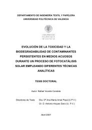
Figure <strong>2.2</strong>.1 shows project organization on three levels:<br />
1. The Project Committee: composed of representatives<br />
from all the sectors involved in the project<br />
(i.e. industries, research centers and electric utilities).<br />
This Committee defines the project guidelines<br />
and takes executive decisions.<br />
2. Project Coordinator: who manages the overall<br />
project in accordance with the guidelines defined<br />
by the Project Committee<br />
3. Task Leaders: the work packages to be performed<br />
in the project are grouped into six Tasks, with a<br />
Task Leader being responsible for the coordination<br />
of all the activities within each Task.
Annual Report ‘97 PSA 30<br />
Fig. <strong>2.2</strong>.1 DISS Project Organization<br />
The following tasks are included in the DISS project<br />
plan:<br />
Coordination and Management: This task includes project<br />
planning, coordination, quality and project control.<br />
Design & Implementation of the PSA DISS test facility:<br />
This task includes the design, procurement and erection of<br />
the PSA DISS test facility, which is to be erected in two<br />
stages, a single-row system during the first phase of the<br />
project and a parallel row to be added at a later stage after<br />
enough information and experience has been gathered with<br />
the single row. Simulations have pointed out that severe<br />
transients could occur in a large DSG solar field when<br />
there are cloud transients and, therefore, implementation<br />
of the second row of collectors is considered essential.<br />
This facility will be a key tool for life-size investigation of<br />
the three DSG processes (i.e., once-through, recirculation<br />
and injection).<br />
Testing and Operation: this task includes the operation<br />
and maintenance of the PSA DISS test facility. Tests will<br />
attempt to find out the answers to some open questions<br />
about the DSG process that cannot be found at smaller<br />
test facilities.<br />
DSG Applied Research: Thermohydraulic aspects of DSG<br />
technology complementing the experimental results gathered<br />
at the PSA will also be investigated. Process control<br />
schemes and heat transfer enhancement mechanisms in<br />
the absorbers with two-phase flow will be developed and<br />
evaluated.<br />
Collector Improvements: Possible collector improvements<br />
(e.g., front-surface mirrors, lighter structures, new selec-
31 PSA Annual Report ‘97<br />
tive coatings, anti-reflective coatings, etc.) will be studied<br />
and evaluated in this task. An oil test loop is currently being<br />
erected at the PSA for used as a test bed to evaluate<br />
improved components under real solar conditions.<br />
System Integration: Operation, maintenance and cost issues<br />
for a commercial DSG power plant will be analyzed<br />
taking into account the experimental results gathered at<br />
the PSA DSG test facility. The lay-out and configuration of<br />
a demonstration commercial plant using the DSG technology<br />
will be prepared.<br />
Summary of activities in 1997<br />
1997 activities were performed under the Design & Implementation<br />
of the PSA DISS Test Facility, DSG Applied Research<br />
and Collector Improvement tasks, as well as overall<br />
project coordination and management, as summarized in<br />
the following paragraphs.<br />
Regarding design and implementation of the PSA DSG<br />
test facility, most of the detailed single-row system design<br />
was finished and erection was begun in June, 1997. Technical<br />
specifications for purchase of the equipment were<br />
prepared by the partners involved in the detailed facility<br />
design. Most of the BOP equipment was purchased by<br />
CIEMAT. Though technical problems concerning the solar<br />
field foundation design delayed the starting date of the<br />
collector assembly, these problems were solved in the last<br />
quarter of 1997 and foundations could be laid at the end<br />
of November. The collector assembly jigs were installed on<br />
site by INABENSA the first week in December. Construction<br />
of the BOP building was begun in October and the<br />
steel structure was erected in November. The long absorber<br />
pipe delivery period and the problems with foundations<br />
have delayed construction of the test facility by another<br />
2 months in the second half of 1997. After a difficult<br />
search, a supplier for the recirculation pump was found<br />
and the purchasing contract will be signed in January,<br />
1998. Samples of high pressure ball joints to connect the<br />
collectors have been tested by the PSA with the collaboration<br />
of ENDESA, solving this technical constraint. The PSA<br />
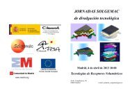
DISS test facility system configuration is shown in Fig.<br />
<strong>2.2</strong>.2, while Fig. <strong>2.2</strong>.3 shows some parabolic-trough modules<br />
during assembly.
Annual Report ‘97 PSA 32<br />
Fig. <strong>2.2</strong>.2 Updated diagram of the PSA DISS test facility<br />
g. <strong>2.2</strong>.3 Some parabolic trough modules for the DISS solar field<br />
Under the "DSG Applied Research" task, DLR has continued<br />
to develop special test equipment for DSG experiments<br />
at the PSA. A draft of the test plan to be performed<br />
at the PSA DISS facility has been prepared and will continue<br />
to be discussed in 1998. Possible absorber pipe heat<br />
transfer enhancement mechanisms have been analyzed<br />
and the study of porous coatings was started.<br />
Within the "Collector Improvement" Task, the PSA HTF<br />
test loop was finished and this facility is now available to<br />
external users for parabolic-trough collector component<br />
testing under real solar conditions. This test stand, built<br />
from half an LS-3 collector, and provided with oil pump,
33 PSA Annual Report ‘97<br />
cooler and heater, as well as an oil expansion tank, can<br />
work at up to 400 C. (Shown in Fig. <strong>2.2</strong>.4.) The local control<br />
developed for parabolic trough collectors by the PSA in<br />
1996 was successfully tested in 1997. CIEMAT has continued<br />
the development of new selective coatings and Sol-<br />
Gel front-surface mirrors.<br />
Fig. <strong>2.2</strong>.4 The PSA HTF test loop
Annual Report ‘97 PSA 34<br />
<strong>2.2</strong>.2 ARDISS Project<br />
The ARDISS (Advanced Receiver for Direct Solar Steam)<br />
project was financed 50% by the CEC Joule II program and<br />
50% by the partners (CIEMAT, ZSW, CONPHOEBUS and<br />
INETI). The project started in December, 1994 and finished<br />
in March 1997. The goal of the ARDISS project is to<br />
analyze the technical options of the DISS process, identified<br />
as the most promising development for speeding up<br />
commercialization of solar-powered electricity production,<br />
and to develop an advanced receiver fulfilling its requirements.<br />
For this, the most promising component developments<br />
in recent years, in particular a Second Stage Concentrator<br />
(SSC) receiver, to increase concentration without<br />
penalizing collector efficiency and improve control of the<br />
DISS process, were integrated. The main tasks performed<br />
were:<br />
• Design, construction and testing of the Second Stage<br />
Concentrator Receiver.<br />
• Theoretical and experimental studies in Direct Steam<br />
Generation.<br />
• Simulations for assessment of DISS solar-driven electricity<br />
production systems.<br />
• Final report<br />
<strong>2.2</strong>.5 Thermal Image of the ARDISS in tracking mode<br />
Among the main results were:<br />
• Although on-sun experiments showed poor behavior,<br />
performance during optical and thermal measurement<br />
in the new SSC lab was good, demonstrating that, once<br />
the problems encountered have been corrected, SSC re-
35 PSA Annual Report ‘97<br />
ceivers will be an excellent alternative for parabolictrough<br />
collectors.<br />
• The new front-surface mirror (Silver protected by a Sol-<br />
Gel-coated SiO 2 layer), has great potential from the<br />
point of view of efficiency and mirror cost, not only for<br />
high-temperature secondary receiver mirrors, but also<br />
for primary parabolic-trough, heliostat and dish mirrors,<br />
although further improvement of durability is needed.<br />
• The HIPRESS experimental facilities have demonstrated<br />
that an SSC receiver simplifies DSG system configuration,<br />
broadens the range of permissible flow rates and<br />
that the range of operating conditions under which the<br />
DSG process can be controlled is wider than expected.<br />
• SSC receivers used for the DSG process improve annual<br />
electricity production by over 20% when compared to<br />
parabolic trough systems with round receivers and oil<br />
as the heat transfer medium.<br />
Fig. <strong>2.2</strong>.6. Detail of ARDISS Receiver.<br />
Summary of activities in 1997<br />
Due to some problems with mirror durability, fabrication<br />
of the ARDISS SSR (Secondary Stage Receiver) was<br />
somewhat delayed, However, it was completed at the end<br />
of 1996, so the SSR absorber was installed at the PSA test<br />
bed in February and evaluated in the first quarter of 1997.
Annual Report ‘97 PSA 36<br />
Helioman test stand modifications made to install the<br />
ARDISS SSC were completed on January 14, 1997 and the<br />
prototype was installed on February 27, 1997, after which<br />
time the receiver testing and evaluation were carried out.<br />
The main tests were:<br />
• Thermal loss<br />
• Efficiency<br />
• Thermal Image processing<br />
Tracking accuracy was also investigated in depth.<br />
For this purpose a device to measure angle was designed<br />
and installed by the engineering department.
37 PSA Annual Report ‘97<br />
<strong>2.2</strong>.3 PAREX Project<br />
This German project managed by the DLR is aimed at<br />
developing and testing advanced parabolic-trough receivers<br />
to:<br />
1. reduce losses at increased working temperatures<br />
2. reduce thermomechanical loads due to cyclic or uneven<br />
heating<br />
These advanced receivers are intended for parabolictrough<br />
collectors with either thermal oil or direct steam<br />
generation. The main role of the PSA in the PAREX project<br />
is the installation of the PAREX absorber prototypes and<br />
their testing under real solar conditions using the ARDISS<br />
and HTF test facilities. A number of new receiver concepts<br />
were analytically and numerically evaluated to select<br />
promising configurations to be built and tested:<br />
1. secondary concentrators<br />
2. linear cavities<br />
3. heat pipe<br />
4. multiple pipes<br />
After the durability and efficiency of the PAREX 02 prototype<br />
was demonstrated on a smaller scale in 1996 and<br />
1997 in the ARDISS test bed, DLR will manufacture a<br />
larger prototype to be tested at the real-scale LS-3 loop<br />
which uses the same collectors as the SEGS Plants in California<br />
currently producing electricity.<br />
The main PAREX project activities at the PSA in 1997<br />
were:<br />
• Modification of the PAREX 02 prototype by the PSA<br />
Maintenance Department.<br />
• Routine operation of the PAREX 02 prototype for durability,<br />
May-July 1997.<br />
• Thermal evaluation of the bare absorber, September-<br />
December, 1997.
Annual Report ‘97 PSA 38<br />
<strong>2.2</strong>.4 Training and Mobility of Researchers<br />
Control<br />
In the earliest stages of solar energy R&D in the Small<br />
Solar Power Systems project, standard industrial PID<br />
feedback controllers were already found to be incapable of<br />
coping with solar radiation transients, causing unnecessary<br />
shutdown of the solar field and clearly demonstrating<br />
the need for advanced controllers for solar plants. The<br />
main objective of this project is the development and<br />
testing of advanced control algorithms for use in solar<br />
power plants. The ACUREX parabolic though solar collector<br />
field served as a test bed. Apart from solar energy,<br />
there are other manifold motivations for this line of research.<br />
The techniques that have been applied to the<br />
ACUREX field may also be applied to many industrial processes<br />
and the work carried out has in turn served as an<br />
impulse for new theoretical development.<br />
The project has been running at the PSA since 1990. In<br />
1997, it was financed by the CEC DG XII Training and Mobility<br />
of Researchers program.<br />
The main achievements in 1997 within the framework of<br />
this project are briefly listed below:<br />
1. A separate session devoted to the work at the <strong>Plataforma</strong><br />
Solar de Almería with six papers presented at the<br />
1997 European Control Conference (the most important<br />
control event worldwide in 1997)<br />
2. 100% fulfillment of the weeks committed in the Training<br />
and Mobility of Researchers contract for the second<br />
year.<br />
3. Approval of the Horus project by the Portuguese national<br />
R&D Planning Board.<br />
Besides the main goal mentioned above, this project<br />
has been highly productive academically. Three Ph.D. theses<br />
are currently underway. There was an exchange of<br />
postgraduate students among institutions involved in the<br />
project, Univ. Firenze, INESC and Univ. Bochum. At several<br />
European universities, the project has also had a<br />
strong impact on undergraduates through the PSA student<br />
grant program and has provided industrial experience for<br />
researchers from different European universities.<br />
The institutions involved are having a hard time maintaining<br />
the tight TMR time schedule. In an effort to overcome<br />
this lack of time, a model of ACUREX field accuracy<br />
designed by the University of Seville was distributed<br />
among the participants so they could simulate the performance<br />
of their controllers and adjust them accordingly<br />
before coming to Almería.
39 PSA Annual Report ‘97<br />
A TMR Users Meeting took place in February 1997. At<br />
this event, the results obtained in the first year of the project<br />
were presented and some useful information was distributed<br />
(papers, programs, etc).<br />
The controllers tested under real operating conditions at<br />
the ACUREX Field in 1997 were:<br />
Univ. of Oulu (Finland):<br />
Linguistic Equation Controller<br />
The Linguistic Equation approach provides a flexible environment<br />
for combining expertise in development of intelligent<br />
systems. The knowledge base of the expert system<br />
is represented by linguistic relationships which can be<br />
converted into matrix equations. This year the basic<br />
scheme tested in 1998 was modified by the incorporation<br />
of braking action and unsymmetry effect.<br />
Univ. Firenze (Italy) and INESC (Portugal):<br />
Switching controller.<br />
The switching control strategy has been used to cope<br />
with changes in plant dynamic behavior induced by different<br />
operating conditions. This year the control scheme<br />
incorporated a feed-forward series proposed by the <strong>Plataforma</strong><br />
Solar de Almería.<br />
Univ. of Bochum.<br />
This university collaborated with INESC in the testing of<br />
two controllers, a bank of LQG controllers tuned to work at<br />
different operating points and a non-linear predictive controller.<br />
Other control-related activities<br />
In order to simplify the work of the ACUREX field users,<br />
the PSA has developed a control module linked to the Data<br />
Acquisition System. This program provides an example of<br />
how to deal with the plant monitoring software, reducing<br />
the mixing time.<br />
A simple, quickly implemented feed-forward based on<br />
the energy balance in equilibrium was also developed and<br />
tested in 1997. This scheme, designed by the PSA, was<br />
also used by some of the institutions involved in the control<br />
project.
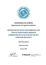
Annual Report ‘97 PSA 40<br />
CONTROL SYSTEMS DEVELOPMENT PROJECT<br />
DATE: 6 May, 1997<br />
1200<br />
300<br />
Solar Rad. (W/m 2 ) Flow*100 (l/s)<br />
1000<br />
800<br />
600<br />
400<br />
200<br />
250<br />
200<br />
150<br />
100<br />
50<br />
Oil Temperature ( oC)<br />
0<br />
0<br />
11 12 13 14 15 16<br />
Local hour (h)<br />
Direct Rad.<br />
Corrected Rad.<br />
Flow*100<br />
Outlet Temp.<br />
Reference Temp.<br />
Inlet Temp.<br />
P.S.A. CONTROLLER<br />
Fig. <strong>2.2</strong>.7. Controller response during a set-point tracking test.
41 PSA Annual Report ‘97<br />
<strong>2.2</strong>.5 TMR Desalination Project<br />
This project deals with the work carried out from 1987<br />
to 1993 within the PSA Solar Thermal Desalination project.<br />
In 1997, two groups were selected as users for the desalination<br />
plant Univ. of Ulster and Heliostat Ltd.<br />
The Univ. of Ulster analyzed the full desalination plant<br />
energy chain. This study showed the very low level of<br />
emissions produced, not only during operation, but<br />
throughout its life cycle from component fabrication to<br />
demolition.<br />
The HELIOSTAT company reviewed the PSA desalination<br />
plant as a test bed for an innovative collector it has developed.<br />
In 1998 this collector will be thermally evaluated<br />
here.<br />
The solar desalination system used for this project, inaugurated<br />
in 1988, is composed of:<br />
• 14-effect MED plant<br />
• parabolic trough solar collector field<br />
• thermocline thermal energy storage tank.<br />
The 14-effect MED plant is shown in Fig. <strong>2.2</strong>.8. The<br />
system operates with Santotherm 55 synthetic thermal oil<br />
as the heat-transfer fluid, which is heated as it circulates<br />
through the solar collectors. The solar energy thus converted<br />
into thermal energy in the form of the sensible heat<br />
of the oil, is stored in the thermal oil tank. Hot oil from<br />
the storage system provides the MED plant with the thermal<br />
energy it requires. The MED plant is composed of 14<br />
cells or effects. The sea water is preheated from Cell to<br />
Cell in the 13 pre-heaters. From Cell (1), the feedwater<br />
goes from one Cell to another by gravity before being extracted<br />
from Cell (14) by the brine pump. Part of the sea<br />
water used to cool the condenser is rejected and the rest is<br />
used for the feed water required to spray the Cell-1 tube<br />
bundle.
Annual Report ‘97 PSA 42<br />
Fig. <strong>2.2</strong>.8. View of the Desalination Plant.<br />
Back: Table of Contents<br />
Back:2 Technical description and project<br />
achievements<br />
Previous Chapter:1 PSA Solar Thermal<br />
<strong>Technology</strong> 1997<br />
Next Chapter: 3 Operation & Maintenance<br />
Previous Section: 2.1 Low Temperature<br />
Applications<br />
Next Section:2.3 Dish/Stirling Systems