HP Probook 4430s Notebook PC HP Probook 4431s - Etilize
HP Probook 4430s Notebook PC HP Probook 4431s - Etilize
HP Probook 4430s Notebook PC HP Probook 4431s - Etilize

You also want an ePaper? Increase the reach of your titles
YUMPU automatically turns print PDFs into web optimized ePapers that Google loves.
<strong>HP</strong> ProBook <strong>4430s</strong> <strong>Notebook</strong> <strong>PC</strong><br />
<strong>HP</strong> ProBook <strong>4431s</strong> <strong>Notebook</strong> <strong>PC</strong><br />
<strong>HP</strong> ProBook 4330s <strong>Notebook</strong> <strong>PC</strong><br />
<strong>HP</strong> ProBook 4331s <strong>Notebook</strong> <strong>PC</strong><br />
Maintenance and Service Guide
© Copyright 2011 Hewlett-Packard<br />
Development Company, L.P.<br />
Bluetooth is a trademark owned by its<br />
proprietor and used by Hewlett-Packard<br />
Company under license. Intel and Core are<br />
trademarks or registered trademarks of Intel<br />
Corporation in the United States and other<br />
countries. Microsoft, Windows, and<br />
Windows Vista are either trademarks or<br />
registered trademarks of Microsoft<br />
Corporation in the United States and/or<br />
other countries. SD Logo is a trademark of<br />
its proprietor.<br />
The information contained herein is subject<br />
to change without notice. The only<br />
warranties for <strong>HP</strong> products and services are<br />
set forth in the express warranty statements<br />
accompanying such products and services.<br />
Nothing herein should be construed as<br />
constituting an additional warranty. <strong>HP</strong> shall<br />
not be liable for technical or editorial errors<br />
or omissions contained herein.<br />
Second Edition: May 2011<br />
First Edition: March 2011<br />
Document Part Number: 643393-002
Safety warning notice<br />
WARNING! To reduce the possibility of heat-related injuries or of overheating the computer, do not<br />
place the computer directly on your lap or obstruct the computer air vents. Use the computer only on a<br />
hard, flat surface. Do not allow another hard surface, such as an adjoining optional printer, or a soft<br />
surface, such as pillows or rugs or clothing, to block airflow. Also, do not allow the AC adapter to<br />
contact the skin or a soft surface, such as pillows or rugs or clothing, during operation. The computer<br />
and the AC adapter comply with the user-accessible surface temperature limits defined by the<br />
International Standard for Safety of Information Technology Equipment (IEC 60950).<br />
iii
iv Safety warning notice
Table of contents<br />
1 Product description ........................................................................................................... 1<br />
2 External component identification ..................................................................................... 9<br />
Display ................................................................................................................................... 9<br />
Top ...................................................................................................................................... 10<br />
TouchPad ............................................................................................................... 10<br />
Lights ..................................................................................................................... 11<br />
Buttons and fingerprint reader (select models only) ...................................................... 13<br />
Keys ...................................................................................................................... 15<br />
Front ..................................................................................................................................... 17<br />
Left ....................................................................................................................................... 18<br />
Right ..................................................................................................................................... 19<br />
Bottom .................................................................................................................................. 20<br />
3 Illustrated parts catalog .................................................................................................. 21<br />
Service tag ............................................................................................................................ 21<br />
Computer major components ................................................................................................... 22<br />
Display components ............................................................................................................... 29<br />
Plastics Kit ............................................................................................................................. 31<br />
Cable Kit .............................................................................................................................. 32<br />
Mass storage devices ............................................................................................................. 32<br />
Miscellaneous parts ................................................................................................................ 33<br />
Sequential part number listing .................................................................................................. 33<br />
4 Removal and replacement procedures ............................................................................ 42<br />
Preliminary replacement requirements ....................................................................................... 42<br />
Tools required ......................................................................................................... 42<br />
Service considerations ............................................................................................. 42<br />
Plastic parts ............................................................................................. 42<br />
Cables and connectors ............................................................................. 43<br />
Drive handling ......................................................................................... 43<br />
v
vi<br />
Grounding guidelines .............................................................................................. 44<br />
Electrostatic discharge damage .................................................................. 44<br />
Packaging and transporting guidelines ........................................ 45<br />
Workstation guidelines .............................................................. 45<br />
Equipment guidelines ................................................................. 46<br />
Component replacement procedures ........................................................................................ 47<br />
Service tag ............................................................................................................. 47<br />
Battery ................................................................................................................... 48<br />
SIM ....................................................................................................................... 49<br />
Bottom door ........................................................................................................... 50<br />
Optical drive .......................................................................................................... 51<br />
Hard drive ............................................................................................................. 53<br />
Memory modules .................................................................................................... 55<br />
WWAN module ..................................................................................................... 57<br />
WLAN/Bluetooth combo card .................................................................................. 59<br />
Keyboard ............................................................................................................... 64<br />
Fan ....................................................................................................................... 67<br />
Heat sink ................................................................................................................ 69<br />
Processor ............................................................................................................... 71<br />
Top cover ............................................................................................................... 72<br />
RTC battery ............................................................................................................ 79<br />
Modem module ....................................................................................................... 81<br />
Audio board ........................................................................................................... 83<br />
Speaker assembly ................................................................................................... 84<br />
RJ-11 jack cable ...................................................................................................... 87<br />
Quick Launch board ................................................................................................ 89<br />
USB board ............................................................................................................. 92<br />
System board ......................................................................................................... 93<br />
Card reader board .................................................................................................. 97<br />
Power cable ........................................................................................................... 99<br />
Optical drive connector ......................................................................................... 101<br />
Display assembly .................................................................................................. 103<br />
5 Computer Setup (BIOS) and System Diagnostics ............................................................ 111<br />
Using Computer Setup .......................................................................................................... 111<br />
Starting Computer Setup ........................................................................................ 111<br />
Navigating and selecting in Computer Setup ............................................................ 111<br />
Restoring factory settings in Computer Setup ............................................................. 112<br />
Updating the BIOS ................................................................................................ 113<br />
Determining the BIOS version .................................................................. 113<br />
Downloading a BIOS update ................................................................... 114
Using System Diagnostics ...................................................................................................... 115<br />
6 Specifications ............................................................................................................... 116<br />
Computer specifications ........................................................................................................ 116<br />
33.8-cm (13.3-in), HD display specifications ........................................................................... 117<br />
35.6-cm (14.0-in), HD display specifications ........................................................................... 118<br />
Hard drive specifications ...................................................................................................... 119<br />
Blu-ray BD-R/RE DVD±RW SuperMulti DL Drive ........................................................................ 120<br />
DVD±RW and CD-RW SuperMulti DL Combo Drive specifications .............................................. 121<br />
Blu-ray ROM DVD±RW SuperMulti DL Drive ............................................................................ 122<br />
DVD-ROM Drive specifications ............................................................................................... 123<br />
Specification information in Device Manager .......................................................................... 124<br />
7 Backup and recovery .................................................................................................... 125<br />
Windows 7 ......................................................................................................................... 125<br />
Backing up your information ................................................................................... 126<br />
Performing a system recovery ................................................................................. 126<br />
Using the Windows recovery tools ........................................................... 127<br />
Using f11 recovery tools ......................................................................... 127<br />
Using a Windows 7 operating system DVD (purchased separately) .............. 128<br />
Windows Vista .................................................................................................................... 129<br />
Backing up your information ................................................................................... 129<br />
Performing a recovery ............................................................................................ 130<br />
Using the Windows recovery tools ........................................................... 130<br />
Using f11 recovery tools ......................................................................... 131<br />
Using a Windows Vista operating system DVD (purchased separately) ......... 132<br />
8 Power cord set requirements ........................................................................................ 133<br />
Requirements for all countries and regions ............................................................................... 133<br />
Requirements for specific countries and regions ....................................................................... 134<br />
9 Recycling ...................................................................................................................... 135<br />
Battery ................................................................................................................................ 135<br />
Display ............................................................................................................................... 135<br />
Index ............................................................................................................................... 141<br />
vii
viii
1 Product description<br />
Category Description <strong>4430s</strong><br />
(UMA)<br />
Product Name <strong>HP</strong> ProBook <strong>4430s</strong> <strong>Notebook</strong> <strong>PC</strong> √<br />
<strong>4430s</strong>/<br />
<strong>4431s</strong><br />
(disc)<br />
<strong>HP</strong> ProBook <strong>4431s</strong> <strong>Notebook</strong> <strong>PC</strong> √<br />
4330s<br />
(UMA)<br />
<strong>HP</strong> ProBook 4330s <strong>Notebook</strong> <strong>PC</strong> √<br />
<strong>HP</strong> ProBook 4331s <strong>Notebook</strong> <strong>PC</strong> √<br />
Processors Intel® Core i7 processor, Dual Core<br />
2620M, 2.70-GHz (Turbo up to 3.40) processor 4-<br />
MB L3 cache, 4 threads<br />
Intel® Core i5 processors, Dual Core<br />
2540M, 2.60-GHz (Turbo up to 3.30) processor 3-<br />
MB L3 cache, 4 threads<br />
2520M, 2.50-GHz (Turbo up to 3.20) processor 3-<br />
MB L3 cache, 4 threads<br />
2410M, 2.30-GHz (Turbo up to 2.90) processor 3-<br />
MB L3 cache, 4 threads<br />
Intel Core i3 processors, Dual Core<br />
4330s/<br />
4331s<br />
(disc)<br />
√ √ √ √<br />
√ √ √ √<br />
√ √ √ √<br />
√ √ √ √<br />
2310M, 2.10-GHz processor 3-MB L3 cache √ √ √ √<br />
Intel Celeron processor, Dual Core<br />
B810, 1.60-GHz processor 2-MB L3 cache, 2<br />
threads<br />
√ √ √ √<br />
Chipset Mobile Intel HM65 chipset √ √ √ √<br />
Graphics Intel HD Graphics 3000 (UMA) √ √<br />
AMD Radeon HD 6490M, 512-MB or 1-GB<br />
(discrete)<br />
Panel All display assemblies include 2 wireless local area<br />
network (WLAN) antennas<br />
33.8-cm (13.3-inch) HD, 1366x768 √ √<br />
√ √<br />
√ √<br />
1
Category Description <strong>4430s</strong><br />
(UMA)<br />
33.8-cm (13.3-inch) HD, 1366x768, includes<br />
camera<br />
33.8-cm (13.3-inch) HD, 1366x768, includes<br />
camera and WWAN<br />
<strong>4430s</strong>/<br />
<strong>4431s</strong><br />
(disc)<br />
√ √<br />
33.8-cm (13.3-inch) HD, BrightView, 1366x768 √ √<br />
33.8-cm (13.3-inch) HD, BrightView, 1366x768,<br />
includes camera<br />
33.8-cm (13.3-inch) HD, BrightView, 1366x768,<br />
includes camera and WWAN<br />
√<br />
√<br />
√ √<br />
√<br />
4330s<br />
(UMA)<br />
4330s/<br />
4331s<br />
(disc)<br />
35.6-cm (14.0-inch) HD, 1366x768 √ √<br />
35.6-cm (14.0-inch) HD, 1366x768, with camera √ √<br />
35.6-cm (14.0-inch) HD, BrightView, 1366x768 √ √<br />
35.6-cm (14.0-inch) HD, BrightView, 1366x768,<br />
with camera<br />
√ √<br />
Support privacy filter √ √ √ √<br />
Memory Two customer-accessible/upgradeable memory<br />
module slots supporting up to 8 GB of RAM<br />
2 Chapter 1 Product description<br />
√ √ √ √<br />
Supports dual-channel memory √ √ √ √<br />
<strong>PC</strong>3-10600, 1333-MHz, DDR3 √ √ √ √<br />
Supports the following configurations:<br />
1333-MHz <strong>PC</strong>3-10600 DDR3:<br />
● 8192 (4096 × 2)<br />
● 4096 (2048 × 2)<br />
● 4096 (4096 × 1)<br />
● 3072 (2048 + 1024)<br />
● 2048 (2048 × 1)<br />
● 2048 (1024 × 2)<br />
● 1024 (1024 × 1)<br />
Brazil DDR3 <strong>PC</strong>3-10600 1333 Mhz:<br />
● 4096 (2048 × 2)<br />
● 4096 (4096 × 1)<br />
● 3072 (2048 + 1024)<br />
● 2048 (2048 × 1)<br />
√ √ √ √<br />
√
Category Description <strong>4430s</strong><br />
(UMA)<br />
Hard drives Supports 9.5-mm or 7-mm, 6.35-cm (2.50-in) SATA<br />
hard drives with <strong>HP</strong> DriveGuard<br />
Fixed optical<br />
drives<br />
<strong>4430s</strong>/<br />
<strong>4431s</strong><br />
(disc)<br />
4330s<br />
(UMA)<br />
4330s/<br />
4331s<br />
(disc)<br />
√ √ √ √<br />
Customer-accessible √ √ √ √<br />
Supports the following drives:<br />
● 750-GB, 7200-rpm<br />
● 500-GB, 7200-rpm<br />
● 320-GB, 7200-rpm<br />
● 250-GB, 7200-rpm<br />
● 640-GB, 5400-rpm<br />
● 500-GB, 5400-rpm<br />
● 320-GB, 5400-rpm<br />
● 250-GB, 5400-rpm<br />
Supports the following 12.7-mm SATA optical<br />
drives:<br />
● DVD-ROM<br />
● DVD+/-RW SuperMulti DL<br />
● Blu-ray ROM DVD+/-RW SuperMulti DL<br />
● Blu-ray R/RE DVD +/-RW SuperMulti DL Drive<br />
√ √ √ √<br />
√ √ √ √<br />
Supports no optical drive option √ √ √ √<br />
Audio/Visual Integrated dual-array microphone (webcam models<br />
only)<br />
√ √ √ √<br />
Integrated mono (non-webcam models) √ √ √ √<br />
Stereo speakers (2) √ √ √ √<br />
Integrated webcam (720p HD) √ √ √ √<br />
Supports no camera option √ √ √ √<br />
Headphone and microphone jacks √ √ √ √<br />
Modem 56K V.92 MDC data/fax modem √ √ √ √<br />
Brazil RCTO (MDC1.5) √<br />
Modem cable not included √ √ √ √<br />
Supports “No Modem” option √ √ √ √<br />
Ethernet Realtek RTL8151EH-CG 10/100/1000 √ √ √ √<br />
S3/S4/S5 wake on LAN √ √ √ √<br />
3
Category Description <strong>4430s</strong><br />
(UMA)<br />
<strong>4430s</strong>/<br />
<strong>4431s</strong><br />
(disc)<br />
4330s<br />
(UMA)<br />
4330s/<br />
4331s<br />
(disc)<br />
Ethernet cable not included √ √ √ √<br />
Wireless Integrated WLAN options by way of wireless module:<br />
External media<br />
card<br />
Two WLAN antennas built into display assembly √ √ √ √<br />
Supports “no WLAN” option √ √ √ √<br />
Supports the following WLAN formats:<br />
● Ralink 802.11 b/g/n 1×1<br />
● Realtek 802.11 b/g/n 1×1<br />
● Atheros 802.11 b/g/n +BT Combo<br />
● Ralink 802.11 a/b/g/n +BT Combo<br />
● Realtek 802.11 b/g/n +BT Combo<br />
● Intel 802.11 a/b/g/n 2×2 +BT Combo<br />
Integrated WWAN options by way of wireless module:<br />
Two WWAN antennas built into display assembly<br />
(world-wide 5 band, configured with panels on all<br />
units)<br />
Subscriber identity module (SIM) security (customeraccessible<br />
in battery bay)<br />
Supports “no WWAN” option √<br />
Supports the following WWAN modules:<br />
● Qualcomm Gobi 3000 HSPA/CDMA with GPS<br />
● Ericsson 5521 HSPA+<br />
● Ericsson F3307-900<br />
√ √ √ √<br />
Integrated personal area network (PAN) options by way of Bluetooth® module:<br />
Bluetooth 3.0 only supported by combo card √ √ √ √<br />
One ExpressCard 34mm slot √ √ √ √<br />
6-in-1 Digital Media Reader Slot √ √ √ √<br />
Ports Audio-in (stereo microphone) √ √ √ √<br />
4 Chapter 1 Product description<br />
Audio-out (stereo headphone) √ √ √ √<br />
RJ-11 (modem) √ √ √ √<br />
RJ-45 (Ethernet, includes link and activity lights) √ √ √ √<br />
USB 2.0 (3) √ √ √ √<br />
√<br />
√<br />
√
Category Description <strong>4430s</strong><br />
(UMA)<br />
Keyboard/<br />
pointing devices<br />
Power<br />
requirements<br />
VGA (Dsub 15-pin) supporting 1600 × 1200<br />
external resolution at 75-GHz (hot plug/unplug with<br />
auto-detect)<br />
<strong>4430s</strong>/<br />
<strong>4431s</strong><br />
(disc)<br />
4330s<br />
(UMA)<br />
4330s/<br />
4331s<br />
(disc)<br />
√ √ √ √<br />
HDMI √ √ √ √<br />
Multi-pin AC port √ √ √ √<br />
Full-sized keyboard √ √ √ √<br />
Touchpad includes: supports 2-way scroll with<br />
legend, taps enabled by default, 2-finger scrolling<br />
and zoom enabled by default<br />
Smart AC adapter with localized cable plug support<br />
(3-wire plug with ground pin):<br />
√ √ √ √<br />
√ √ √ √<br />
90-W √ √<br />
65-W √ √<br />
9-cell, 93-Wh Li-ion battery √ √ √ √<br />
6-cell, 55-Wh Li-ion battery √ √ √ √<br />
6-cell, 47-Wh Li-ion battery √ √ √ √<br />
Security Integrated fingerprint reader √ √ √ √<br />
Operating system Preinstalled:<br />
Intel AT support √ √ √ √<br />
Support Kensington security lock √ √ √ √<br />
Support no fingerprint reader option √ √ √ √<br />
Windows 7 Professional 32 with Microsoft® Basics √ √ √ √<br />
Windows 7 Professional 64 with Microsoft Basics √ √ √ √<br />
Windows 7 Home Premium 64 with Microsoft Basics √ √ √ √<br />
Windows 7 Home Premium 32 with Microsoft Basics √ √ √ √<br />
Windows 7 Home Basic 32 with Microsoft Basics √ √<br />
Windows Vista Home Basic 32 with Microsoft<br />
Basics<br />
√ √<br />
Novell: SuSE Linux – SLED 11 √ √ √ √<br />
FreeDOS √ √ √ √<br />
Preinstalled with Microsoft Office:<br />
Windows 7 Professional 32 with Microsoft Office<br />
2010 Starter MSNA<br />
√ √<br />
5
Category Description <strong>4430s</strong><br />
(UMA)<br />
6 Chapter 1 Product description<br />
Windows 7 Professional 32 with Microsoft Office<br />
2010 Starter EDGI<br />
Windows 7 Professional 32 with Microsoft Office<br />
2010 Starter<br />
Windows 7 Professional 32 with Microsoft Office<br />
2010 Personal<br />
Windows 7 Professional 32 with Microsoft Office<br />
2010 Home & Business<br />
Windows 7 Professional 32 with Microsoft Office<br />
2010 Professional<br />
Windows 7 Professional 64 with Microsoft Office<br />
2010 Starter MSNA<br />
Windows 7 Professional 64 with Microsoft Office<br />
2010 Starter EDGI<br />
Windows 7 Professional 64 with Microsoft Office<br />
2010 Starter<br />
Windows 7 Professional 64 with Microsoft Office<br />
2010 Personal<br />
Windows 7 Professional 64 with Microsoft Office<br />
2010 Home & Business<br />
Windows 7 Professional 64 with Microsoft Office<br />
2010 Professional<br />
Windows 7 Home Premium 32 with Microsoft Office<br />
2010 Starter EDGI<br />
Windows 7 Home Premium 32 with Microsoft Office<br />
2010 Starter<br />
Windows 7 Home Premium 32 with Microsoft Office<br />
2010 Personal<br />
Windows 7 Home Premium 32 with Microsoft Office<br />
2010 Home & Business<br />
Windows 7 Home Premium 32 with Microsoft Office<br />
2010 Professional<br />
Windows 7 Home Premium 64 with Microsoft Office<br />
2010 Starter EDGI<br />
Windows 7 Home Premium 64 with Microsoft Office<br />
2010 Starter<br />
Windows 7 Premium 64 with Microsoft Office 2010<br />
Professional<br />
Windows 7 Starter with Microsoft Office 2010<br />
Starter<br />
<strong>4430s</strong>/<br />
<strong>4431s</strong><br />
(disc)<br />
4330s<br />
(UMA)<br />
4330s/<br />
4331s<br />
(disc)<br />
√ √ √ √<br />
√ √ √ √<br />
√ √ √ √<br />
√ √ √ √<br />
√ √ √ √<br />
√ √<br />
√ √ √ √<br />
√ √ √ √<br />
√ √ √ √<br />
√ √ √ √<br />
√ √ √ √<br />
√ √ √ √<br />
√ √ √ √<br />
√ √ √ √<br />
√ √ √ √<br />
√ √ √ √<br />
√ √ √ √<br />
√ √ √ √<br />
√ √ √ √<br />
√ √ √ √
Category Description <strong>4430s</strong><br />
(UMA)<br />
Windows 7 Home Basic 32 with Microsoft Office<br />
2010 Starter EDGI<br />
Windows 7 Home Basic 32 with Microsoft Office<br />
2010 Starter<br />
Windows Vista Basic 32 with Microsoft Office 2010<br />
Starter<br />
Windows Vista Basic 32 with Microsoft Office 2010<br />
Personal<br />
Windows Vista Basic 32 with Microsoft Office 2010<br />
Home & Business<br />
Windows Vista Basic 32 with Microsoft Office 2010<br />
Professional<br />
<strong>4430s</strong>/<br />
<strong>4431s</strong><br />
(disc)<br />
4330s<br />
(UMA)<br />
√ √<br />
√ √<br />
√ √<br />
√ √<br />
√ √<br />
√ √<br />
Windows 7 Starter with Office 2010 Preload √ √<br />
Windows 7 Starter with Office 2007 Ready - EDGI √ √<br />
Restore Media:<br />
4330s/<br />
4331s<br />
(disc)<br />
Windows 7 Professional 64 √ √ √ √<br />
Windows 7 Professional 32 √ √ √ √<br />
Windows 7 Home Basic 32 √ √ √ √<br />
Windows 7 Home Premium 64 √ √ √ √<br />
Windows 7 Home Premium 32 √ √ √ √<br />
Windows 7 Starter √ √ √ √<br />
DRDVD Windows 7 √ √ √ √<br />
Windows Vista – through Service only √ √ √ √<br />
Web-only support:<br />
Windows XP Professional √ √ √ √<br />
Certified:<br />
Microsoft WHQL √ √ √ √<br />
Serviceability End-user replaceable parts:<br />
AC adapter √ √ √ √<br />
Battery (system) √ √ √ √<br />
Hard drive √ √ √ √<br />
Memory module √ √ √ √<br />
Optical drive √ √ √ √<br />
WLAN module √ √ √ √<br />
7
Category Description <strong>4430s</strong><br />
(UMA)<br />
8 Chapter 1 Product description<br />
WWAN module, SIM √<br />
<strong>4430s</strong>/<br />
<strong>4431s</strong><br />
(disc)<br />
4330s<br />
(UMA)<br />
4330s/<br />
4331s<br />
(disc)<br />
Keyboard √ √ √ √
2 External component identification<br />
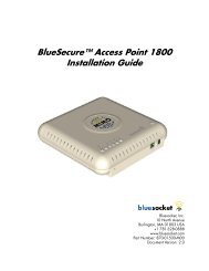
Display<br />
Component Description<br />
(1) Speakers (2) Produce sound.<br />
(2) Internal display switch Turns off the display or initiates Sleep if the display is closed<br />
while the power is on.<br />
NOTE: The display switch is not visible from the outside of the<br />
computer.<br />
(3) WWAN antennas (2)* (select models only) Send and receive wireless signals to communicate with wireless<br />
wide-area networks (WWAN).<br />
(4) WLAN antennas (2)* Send and receive wireless signals to communicate with wireless<br />
local area networks (WLAN).<br />
(5) Internal microphone(s) (1 or 2 depending on<br />
model)<br />
Record sound.<br />
Display 9
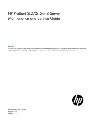
Top<br />
TouchPad<br />
Component Description<br />
(6) Webcam light (select models only) On: The webcam is in use.<br />
(7) Webcam (select models only) Records video and captures still photographs.<br />
To use the webcam, select Start > All Programs > ArcSoft<br />
TotalMedia Suite > WebCam Companion.<br />
*The antennas are not visible from the outside of the computer. For optimal transmission, keep the areas immediately around<br />
the antennas free from obstructions. To see wireless regulatory notices, refer to the section of the Regulatory, Safety, and<br />
Environmental Notices that applies to your country or region. These notices are located in Help and Support.<br />
Component Description<br />
(1) TouchPad on/off button Turns the TouchPad on and off.<br />
(2) TouchPad Moves the pointer and selects or activates items on the<br />
screen.<br />
(3) Left TouchPad button Functions like the left button on an external mouse.<br />
(4) Right TouchPad button Functions like the right button on an external mouse.<br />
10 Chapter 2 External component identification
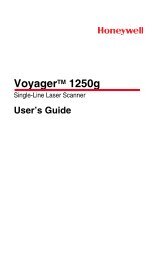
Lights<br />
Component Description<br />
(1) TouchPad light ● Amber: The TouchPad is off.<br />
● Off: The TouchPad is on.<br />
(2) Caps lock light ● White: Caps lock is on.<br />
● Off: Caps lock is off.<br />
(3) Power light ● On: The computer is on.<br />
● Blinking: The computer is in the Sleep state.<br />
● Off: The computer is off or in Hibernation.<br />
Top 11
Component Description<br />
(4) QuickWeb light ● On: The computer is on or the default Web browser is<br />
in use.<br />
● Blinking: When the QuickWeb button is pressed, the<br />
light blinks 5 times, and then the default Web browser<br />
opens.<br />
NOTE: To use <strong>HP</strong> QuickWeb when the computer is off, <strong>HP</strong><br />
QuickWeb must be enabled in Computer Setup<br />
(5) Wireless light ● White: An integrated wireless device, such as a wireless<br />
local area network (WLAN) device and/or a<br />
Bluetooth® device, is on.<br />
12 Chapter 2 External component identification<br />
● Amber: All wireless devices are off.
Buttons and fingerprint reader (select models only)<br />
Component Description<br />
(1) Power button ● When the computer is off, press the button to turn on the<br />
computer.<br />
● When the computer is on, press the button briefly to<br />
initiate Sleep.<br />
● When the computer is in the Sleep state, press the<br />
button briefly to exit Sleep.<br />
● When the computer is in Hibernation, press the button<br />
briefly to exit Hibernation.<br />
If the computer has stopped responding and Windows®<br />
shutdown procedures are ineffective, press and hold the<br />
power button for at least 5 seconds to turn off the computer.<br />
To learn more about your power settings:<br />
● Windows 7—Select Start > Control Panel ><br />
System and Security > Power Options.<br />
● Windows Vista—Select Start > Control Panel ><br />
System and Maintenance > Power Options<br />
● Or refer to the <strong>HP</strong> <strong>Notebook</strong> Reference Guide.<br />
Top 13
Component Description<br />
(2) QuickWeb button ● When the computer is off or in Hibernation, press the<br />
button to open <strong>HP</strong> QuickWeb.<br />
● When the computer is in Microsoft Windows, press the<br />
button to open the default Web browser.<br />
● When the computer is in <strong>HP</strong> QuickWeb, press the<br />
button to open the default Web browser.<br />
NOTE: For more information, refer to “<strong>HP</strong> QuickWeb” in<br />
this guide and to the <strong>HP</strong> QuickWeb software Help. If your<br />
computer does not have <strong>HP</strong> QuickWeb software, the button<br />
does not perform any action or function.<br />
(3) Wireless button Turns the wireless feature on or off but does not establish a<br />
wireless connection.<br />
(4) Fingerprint reader (select models only) Allows a fingerprint logon to Windows, instead of a<br />
password logon.<br />
14 Chapter 2 External component identification
Keys<br />
NOTE: Refer to the illustration that most closely matches your computer.<br />
Component Description<br />
(1) esc key Displays system information when pressed in combination<br />
with the fn key.<br />
(2) Function keys Execute frequently used system functions when pressed in<br />
combination with the fn key.<br />
(3) num lk key Enables/disables the embedded numeric keypad when<br />
pressed in combination with the fn key.<br />
(4) fn key Executes frequently used system functions when pressed in<br />
combination with a function key, the num lk key, or the esc<br />
key.<br />
(5) Start key Displays the Start menu.<br />
(6) Embedded numeric keypad keys Can be used like the keys on an external numeric keypad<br />
when pressed in combination with the fn and num lk keys.<br />
(7) Menu key Displays the active program's shortcut menu (same as the<br />
right-click menu).<br />
Top 15
Component Description<br />
(1) esc key Displays system information when pressed in combination<br />
with the fn key.<br />
(2) Function keys Execute frequently used system functions when pressed in<br />
combination with the fn key.<br />
(3) num lk key Enables/disables the embedded numeric keypad when<br />
pressed in combination with the fn key.<br />
(4) Integrated numeric keypad When the keypad has been enabled, the keys can be used<br />
like an external numeric keypad.<br />
(5) fn key Executes frequently used system functions when pressed in<br />
combination with a function key, the num lk key, or the esc<br />
key.<br />
(6) Start key Displays the Start menu.<br />
(7) Menu key Displays the active program's shortcut menu (same as the<br />
right-click menu)..<br />
16 Chapter 2 External component identification
Front<br />
Component Description<br />
(1) Drive light ● White: The hard drive or optical drive is being<br />
accessed.<br />
● Amber: <strong>HP</strong> 3D DriveGuard has temporarily parked the<br />
hard drive.<br />
(2) Media Card Reader Supports the following digital card formats:<br />
● Memory Stick Pro<br />
● Memory Stick Duo Pro<br />
● MultiMediaCard<br />
● MultiMediaCard Micro<br />
● Secure Digital (SD) Card<br />
● Secure Digital (SD) Card Micro<br />
(3) Audio-out (headphone) jack Connects optional headphones, earbuds, a headset, or<br />
television audio.<br />
WARNING! To reduce the risk of personal injury, adjust<br />
the volume before putting on headphones, earbuds, or a<br />
headset. For additional safety information, refer to the<br />
Regulatory, Safety, and Environmental Notices<br />
NOTE: When a device is connected to the jack, the<br />
computer speakers are disabled.<br />
(4) Audio-in (microphone) jack Connects an optional computer headset microphone, stereo<br />
array microphone, or monaural microphone.<br />
Front 17
Left<br />
Component Description<br />
(1) Security cable slot Attaches an optional security cable to the computer.<br />
NOTE: The security cable is designed to act as a deterrent,<br />
but it may not prevent the computer from being mishandled<br />
or stolen.<br />
(2) AC adapter light ● White: The computer is connected to external power<br />
and the battery is 90 to 99% charged.<br />
● Amber: The computer is connected to external power<br />
and the battery is 0 to 90% charged.<br />
● Blinking amber: A battery that is the only available<br />
power source has reached a low battery level. When<br />
the battery reaches a critical battery level, the battery<br />
light begins blinking rapidly.<br />
● Off: The battery is fully charged.<br />
(3) Power connector Connects an AC adapter.<br />
NOTE: If the computer is plugged into an external<br />
power source, the light turns off when all batteries in<br />
the computer are fully charged. If the computer is not<br />
plugged into an external power source, the light stays<br />
off until the battery reaches a low battery level.<br />
(4) Vent Enables airflow to cool internal components.<br />
NOTE: The computer fan starts up automatically to cool<br />
internal components and prevent overheating. It is normal for<br />
the internal fan to cycle on and off during routine operation.<br />
(5) External monitor port Connects an external VGA monitor or projector.<br />
(6) RJ-45 (network) jack Connects a network cable.<br />
18 Chapter 2 External component identification
Right<br />
Component Description<br />
(7) HDMI port Connects an optional video or audio device, such as a highdefinition<br />
television, or any compatible digital or audio<br />
component.<br />
(8) ExpressCard slot Reads and writes to ExpressCards.<br />
(9) USB port Connects an optional USB device.<br />
(10) USB port Connects an optional USB device.<br />
Component Description<br />
(1) USB ports (2) Connect optional USB devices.<br />
(2) RJ-11 (modem) jack (select models only) Connects a modem cable.<br />
(3) Optical drive Reads and writes (select models only) to an optical disc.<br />
(4) Optical drive light Lights when optical drive is active.<br />
(5) Optical drive eject button Ejects the optical drive.<br />
Right 19
Bottom<br />
Component Description<br />
(1) Battery and access cover release latches Release the battery from the battery bay, and the access<br />
cover from the computer.<br />
(2) Battery bay Holds the battery.<br />
(3) SIM slot Contains a wireless subscriber identity module (SIM) (select<br />
models only). The SIM slot is located inside the battery bay.<br />
(4) Vents (2) Enable airflow to cool internal components.<br />
NOTE: The computer fan starts up automatically to cool<br />
internal components and prevent overheating. It is normal<br />
for the internal fan to cycle on and off during routine<br />
operation.<br />
(5) Access door Contains the hard drive, the wireless LAN module slot, and<br />
the memory module slot.<br />
20 Chapter 2 External component identification<br />
CAUTION: To prevent an unresponsive system, replace<br />
the wireless module only with a wireless module authorized<br />
for use in the computer by the governmental agency that<br />
regulates wireless devices in your country or region. If you<br />
replace the module and then receive a warning message,<br />
remove the module to restore computer functionality, and<br />
then contact technical support through Help and Support.
3 Illustrated parts catalog<br />
Service tag<br />
When ordering parts or requesting information, provide the computer serial number and model<br />
description provided on the service tag.<br />
● Product name (1). This is the product name affixed to the front of the computer.<br />
● Serial number (s/n) (2). This is an alphanumeric identifier that is unique to each product.<br />
● Part number/Product number (p/n) (3). This number provides specific information about the<br />
product's hardware components. The part number helps a service technician to determine what<br />
components and parts are needed.<br />
● Warranty period (4). This number describes the duration (in years) of the warranty period for the<br />
computer.<br />
● Model description (5). This is the alphanumeric identifier used to locate documents, drivers, and<br />
support for the computer.<br />
Service tag 21
Computer major components<br />
22 Chapter 3 Illustrated parts catalog
Item Description Spare part<br />
number<br />
(1) Display panel<br />
For use in <strong>HP</strong> ProBook 4330s/4331s models:<br />
● 33.8-cm (13.3-inch) HD, anti-glare, without webcam 646995-001<br />
● 33.8-cm (13.3-inch) HD, anti-glare, with webcam 646996-001<br />
● 33.8-cm (13.3-inch) HD, BrightView, without webcam 646997-001<br />
● 33.8-cm (13.3-inch) HD, BrightView, with webcam 646998-001<br />
● 33.8-cm (13.3-inch) HD, anti-glare, with webcam and WWAN 646999-001<br />
● 33.8-cm (13.3-inch) HD, BrightView, with webcam and WWAN 647000-001<br />
For use in <strong>HP</strong> ProBook <strong>4430s</strong>/<strong>4431s</strong> models:<br />
● 35.6-cm (14.0-inch), anti-glare, without webcam 646991-001<br />
● 35.6-cm (14.0-inch), anti-glare, with webcam 646992-001<br />
● 35.6-cm (14.0-inch), BrightView, without webcam 646993-001<br />
● 35.6-cm (14.0-inch), BrightView, with webcam 646994-001<br />
(2) Keyboard (includes cable)<br />
NOTE: For a detailed list of available keyboards, see Sequential part number listing<br />
on page 33.<br />
(3) Top cover<br />
For use in model 4330s/4331s:<br />
646365-xxx<br />
● With a fingerprint reader and USB 3.0 646331-001<br />
● Without a fingerprint reader and with USB 3.0 646333-001<br />
● With a fingerprint reader and USB 2.0 658336-001<br />
● Without a fingerprint reader and with USB 2.0 658337-001<br />
For use in model <strong>4430s</strong>/<strong>4431s</strong>:<br />
● With a fingerprint reader and USB 3.0 646335-001<br />
● Without a fingerprint reader and with USB 3.0 646337-001<br />
● With a fingerprint reader and USB 2.0 658338-001<br />
● Without a fingerprint reader and with USB 2.0 658339-001<br />
(4) Audio board 647605-001<br />
(5) Card reader board 646361-001<br />
(6) Quick Launch board 646362-001<br />
(7) WWAN modules<br />
<strong>HP</strong> lc2010 HSPA Mobile Broadband Module 612600-001<br />
Computer major components 23
Item Description Spare part<br />
number<br />
<strong>HP</strong> un2430 EV-DO/HSPA Mobile Broadband Module 634400-001<br />
(8) WLAN module<br />
Atheros AR9002WB-1NGB 802.11b/g/n 1x1 WiFi and Bluetooth 2.1+EDR Combo<br />
Adapter for use in Afghanistan, Albania, Algeria, Andorra, Angola, Antigua and Barbuda,<br />
Argentina, Armenia, Aruba, Australia, Austria, Azerbaijan, Bahamas, Bahrain, Bangladesh,<br />
Barbados, Belarus, Belgium, Belize, Benin, Bermuda, Bhutan, Bolivia, Bosnia and<br />
Herzegovina, Botswana, Brazil, the British Virgin Islands, Brunei, Bulgaria, Burkina Faso,<br />
Burundi, Cambodia, Cameroon, Canada, Cape Verde, the Cayman Islands, Central African<br />
Republic, Chad, Chile, People's Republic of China, Colombia, Comoros, Congo, Costa Rica,<br />
Croatia, Cyprus, the Czech Republic, Denmark, Djibouti, Dominica, the Dominican Republic,<br />
East Timor, Ecuador, Egypt, El Salvador, Equitorial Guinea, Eritrea, Estonia, Ethiopia, Fiji,<br />
Finland, France, French Guiana, Gabon, Gambia, Georgia, Germany, Ghana, Gibraltar,<br />
Greece, Grenada, Guadeloupe, Guam, Guatemala, Guinea, Guinea-Bissa, Guyana, Haiti,<br />
Honduras, Hong Kong, Hungary, Iceland, India, Indonesia, Ireland, Israel, Italy, Ivory Coast,<br />
Jamaica, Japan, Jordan, Kazakhstan, Kenya, Kiribati, Kuwait, Kyrgyzstan, Laos, Latvia,<br />
Lebanon, Lesotho, Liberia, Liechtenstein, Lithuania, Luxembourg, Macedonia, Madagascar,<br />
Malawi, Malaysia, Maldives, Mali, Malta, Marshall Islands, Martinique, Mauritania,<br />
Mauritius, Mexico, Micronesia, Monaco, Mongolia, Montenegro, Morocco, Mozambique,<br />
Namibia, Nauru, Nepal, the Nether Antilles, the Netherlands, New Zealand, Nicaragua,<br />
Niger, Nigeria, Norway, Oman, Pakistan, Palau, Panama, Papua New Guinea, Paraguay,<br />
Puerto Rico, Peru, Philippines, Poland, Portugal, Qatar, Republic of Moldova, Romania,<br />
Russia, Rwanda, Samoa, San Marino, Sao Tome and Principe, Saudi Arabia, Senegal,<br />
Serbia and Montenegro, Seychelles, Sierra Leone, Singapore, Slovakia, Slovenia, Solomon<br />
Islands, Somalia, South Africa, South Korea, Spain, Sri Lanka, St. Kitts and Nevis, St. Lucia,<br />
St. Vincent and the Grenadines, Suriname, Swaziland, Sweden, Switzerland, Syria, Taiwan,<br />
Tajikistan, Tanzania, Thailand, Togo, Tonga, Trinidad and Tobago, Tunisia, Turkey,<br />
Turkmenistan, Tuvalu, Uganda, Ukraine, the United Arab Emirates, the United Kingdom,<br />
Uruguay, the United States, the US Virgin Islands, Uzbekistan, Vanuatu, Venezuela, Vietnam,<br />
Yemen, Zaire, Zambia, and Zimbabwe<br />
24 Chapter 3 Illustrated parts catalog<br />
593127-001
Item Description Spare part<br />
number<br />
Realtek 8188BC8 802.11a/b/g/n 2x2 WiFi and Bluetooth 3.0+HS Combo Adapter for use<br />
in Afghanistan, Albania, Algeria, Andorra, Angola, Antigua and Barbuda, Argentina,<br />
Armenia, Aruba, Australia, Austria, Azerbaijan, Bahamas, Bahrain, Baltics, Bangladesh,<br />
Barbados, Belarus, Belgium, Belize, Benin, Bermuda, Bhutan, Bolivia, Bosnia and<br />
Herzegovina, Botswana, Brazil, the British Virgin Islands, Brunei, Bulgaria, Burkina Faso,<br />
Burundi, Cambodia, Cameroon, Canada, Cape Verde, the Cayman Islands, Central African<br />
Republic, Chad, Chile, People's Republic of China, Colombia, Comoros, Congo, Costa Rica,<br />
Croatia, Cyprus, the Czech Republic, Denmark, Djibouti, Dominica, the Dominican Republic,<br />
East Timor, Ecuador, Egypt, El Salvador, Equitorial Guinea, Eritrea, Estonia, Ethiopia, Fiji,<br />
Finland, France, French Guiana, Gabon, Gambia, Georgia, Germany, Ghana, Gibraltar,<br />
Greece, Grenada, Guadeloupe, Guam, Guatemala, Guinea, Guinea-Bissa, Guyana, Haiti,<br />
Honduras, Hong Kong, Hungary, Iceland, India, Indonesia, Iraq, Ireland, Israel, Italy, Ivory<br />
Coast, Jamaica, Japan, Jordan, Kazakhstan, Kenya, Kiribati, Kuwait, Kyrgyzstan, Laos,<br />
Latvia, Lebanon, Lesotho, Liberia, Liechtenstein, Lithuania, Luxembourg, Macedonia,<br />
Madagascar, Malawi, Malaysia, Maldives, Mali, Malta, Marshall Islands, Martinique,<br />
Mauritania, Mauritius, Mexico, Micronesia, Monaco, Mongolia, Montenegro, Morocco,<br />
Mozambique, Namibia, Nauru, Nepal, the Nether Antilles, the Netherlands, New Zealand,<br />
Nicaragua, Niger, Nigeria, Norway, Oman, Pakistan, Palau, Panama, Papua New Guinea,<br />
Paraguay, Puerto Rico, Peru, Philippines, Poland, Portugal, Qatar, Republic of Moldova,<br />
Romania, Russia, Rwanda, Samoa, San Marino, Sao Tome and Principe, Saudi Arabia,<br />
Senegal, Serbia and Montenegro, Seychelles, Sierra Leone, Singapore, Slovakia, Slovenia,<br />
Solomon Islands, Somalia, South Africa, South Korea, Spain, Sri Lanka, St. Kitts and Nevis,<br />
St. Lucia, St. Vincent and the Grenadines, Suriname, Swaziland, Sweden, Switzerland,<br />
Syria, Taiwan, Tajikistan, Tanzania, Thailand, Togo, Tonga, Trinidad and Tobago, Tunisia,<br />
Turkey, Turkmenistan, Tuvalu, Uganda, Ukraine, the United Arab Emirates, the United<br />
Kingdom, Uruguay, the United States, the US Virgin Islands, Uzbekistan, Vanuatu,<br />
Venezuela, Vietnam, Yemen, Zaire, Zambia, and Zimbabwe<br />
Ralink 5390GN 802.11b/g/n 1x1 WiFi Adapter for use in Afghanistan, Albania, Algeria,<br />
Andorra, Angola, Antigua and Barbuda, Argentina, Armenia, Aruba, Australia, Austria,<br />
Azerbaijan, Bahamas, Bahrain, Baltics, Bangladesh, Barbados, Belarus, Belgium, Belize,<br />
Benin, Bermuda, Bhutan, Bolivia, Bosnia and Herzegovina, Botswana, Brazil, the British<br />
Virgin Islands, Brunei, Bulgaria, Burkina Faso, Burundi, Cambodia, Cameroon, Canada,<br />
Cape Verde, the Cayman Islands, Central African Republic, Chad, Chile, People's Republic<br />
of China, Colombia, Comoros, Congo, Costa Rica, Croatia, Cyprus, the Czech Republic,<br />
Denmark, Djibouti, Dominica, the Dominican Republic, East Timor, Ecuador, Egypt, El<br />
Salvador, Equitorial Guinea, Eritrea, Estonia, Ethiopia, Fiji, Finland, France, French Guiana,<br />
Gabon, Gambia, Georgia, Germany, Ghana, Gibraltar, Greece, Grenada, Guadeloupe,<br />
Guam, Guatemala, Guinea, Guinea-Bissa, Guyana, Haiti, Honduras, Hong Kong, Hungary,<br />
Iceland, India, Indonesia, Iraq, Ireland, Israel, Italy, Ivory Coast, Jamaica, Japan, Jordan,<br />
Kazakhstan, Kenya, Kiribati, Kuwait, Kyrgyzstan, Laos, Latvia, Lebanon, Lesotho, Liberia,<br />
Liechtenstein, Lithuania, Luxembourg, Macedonia, Madagascar, Malawi, Malaysia,<br />
Maldives, Mali, Malta, Marshall Islands, Martinique, Mauritania, Mauritius, Mexico,<br />
Micronesia, Monaco, Mongolia, Montenegro, Morocco, Mozambique, Namibia, Nauru,<br />
Nepal, the Nether Antilles, the Netherlands, New Zealand, Nicaragua, Niger, Nigeria,<br />
Norway, Oman, Pakistan, Palau, Panama, Papua New Guinea, Paraguay, Puerto Rico,<br />
Peru, Philippines, Poland, Portugal, Qatar, Republic of Moldova, Romania, Russia, Rwanda,<br />
Samoa, San Marino, Sao Tome and Principe, Saudi Arabia, Senegal, Serbia and<br />
Montenegro, Seychelles, Sierra Leone, Singapore, Slovakia, Slovenia, Solomon Islands,<br />
Somalia, South Africa, South Korea, Spain, Sri Lanka, St. Kitts and Nevis, St. Lucia, St.<br />
Vincent and the Grenadines, Suriname, Swaziland, Sweden, Switzerland, Syria, Taiwan,<br />
Tajikistan, Tanzania, Thailand, Togo, Tonga, Trinidad and Tobago, Tunisia, Turkey,<br />
Turkmenistan, Tuvalu, Uganda, Ukraine, the United Arab Emirates, the United Kingdom,<br />
Uruguay, the United States, the US Virgin Islands, Uzbekistan, Vanuatu, Venezuela, Vietnam,<br />
Yemen, Zaire, Zambia, and Zimbabwe<br />
602993-001<br />
630703-001<br />
Computer major components 25
Item Description Spare part<br />
number<br />
Ralink 8190BC8 802.11b/g/n 2x2 WiFi and Bluetooth 3.0+HS Combo Adapter for use in<br />
Afghanistan, Albania, Algeria, Andorra, Angola, Antigua and Barbuda, Argentina,<br />
Armenia, Aruba, Australia, Austria, Azerbaijan, Bahamas, Bahrain, Baltics, Bangladesh,<br />
Barbados, Belarus, Belgium, Belize, Benin, Bermuda, Bhutan, Bolivia, Bosnia and<br />
Herzegovina, Botswana, Brazil, the British Virgin Islands, Brunei, Bulgaria, Burkina Faso,<br />
Burundi, Cambodia, Cameroon, Canada, Cape Verde, the Cayman Islands, Central African<br />
Republic, Chad, Chile, People's Republic of China, Colombia, Comoros, Congo, Costa Rica,<br />
Croatia, Cyprus, the Czech Republic, Denmark, Djibouti, Dominica, the Dominican Republic,<br />
East Timor, Ecuador, Egypt, El Salvador, Equitorial Guinea, Eritrea, Estonia, Ethiopia, Fiji,<br />
Finland, France, French Guiana, Gabon, Gambia, Georgia, Germany, Ghana, Gibraltar,<br />
Greece, Grenada, Guadeloupe, Guam, Guatemala, Guinea, Guinea-Bissa, Guyana, Haiti,<br />
Honduras, Hong Kong, Hungary, Iceland, India, Indonesia, Iraq, Ireland, Israel, Italy, Ivory<br />
Coast, Jamaica, Japan, Jordan, Kazakhstan, Kenya, Kiribati, Kuwait, Kyrgyzstan, Laos,<br />
Latvia, Lebanon, Lesotho, Liberia, Liechtenstein, Lithuania, Luxembourg, Macedonia,<br />
Madagascar, Malawi, Malaysia, Maldives, Mali, Malta, Marshall Islands, Martinique,<br />
Mauritania, Mauritius, Mexico, Micronesia, Monaco, Mongolia, Montenegro, Morocco,<br />
Mozambique, Namibia, Nauru, Nepal, the Nether Antilles, the Netherlands, New Zealand,<br />
Nicaragua, Niger, Nigeria, Norway, Oman, Pakistan, Palau, Panama, Papua New Guinea,<br />
Paraguay, Puerto Rico, Peru, Philippines, Poland, Portugal, Qatar, Republic of Moldova,<br />
Romania, Russia, Rwanda, Samoa, San Marino, Sao Tome and Principe, Saudi Arabia,<br />
Senegal, Serbia and Montenegro, Seychelles, Sierra Leone, Singapore, Slovakia, Slovenia,<br />
Solomon Islands, Somalia, South Africa, South Korea, Spain, Sri Lanka, St. Kitts and Nevis,<br />
St. Lucia, St. Vincent and the Grenadines, Suriname, Swaziland, Sweden, Switzerland,<br />
Syria, Taiwan, Tajikistan, Tanzania, Thailand, Togo, Tonga, Trinidad and Tobago, Tunisia,<br />
Turkey, Turkmenistan, Tuvalu, Uganda, Ukraine, the United Arab Emirates, the United<br />
Kingdom, Uruguay, the United States, the US Virgin Islands, Uzbekistan, Vanuatu,<br />
Venezuela, Vietnam, Yemen, Zaire, Zambia, and Zimbabwe<br />
Realtek 8188GN 802.11b/g/n 1x1 WiFi Adapter for use in Afghanistan, Albania, Algeria,<br />
Andorra, Angola, Antigua and Barbuda, Argentina, Armenia, Aruba, Australia, Austria,<br />
Azerbaijan, Bahamas, Bahrain, Baltics, Bangladesh, Barbados, Belarus, Belgium, Belize,<br />
Benin, Bermuda, Bhutan, Bolivia, Bosnia and Herzegovina, Botswana, Brazil, the British<br />
Virgin Islands, Brunei, Bulgaria, Burkina Faso, Burundi, Cambodia, Cameroon, Canada,<br />
Cape Verde, the Cayman Islands, Central African Republic, Chad, Chile, People's Republic<br />
of China, Colombia, Comoros, Congo, Costa Rica, Croatia, Cyprus, the Czech Republic,<br />
Denmark, Djibouti, Dominica, the Dominican Republic, East Timor, Ecuador, Egypt, El<br />
Salvador, Equitorial Guinea, Eritrea, Estonia, Ethiopia, Fiji, Finland, France, French Guiana,<br />
Gabon, Gambia, Georgia, Germany, Ghana, Gibraltar, Greece, Grenada, Guadeloupe,<br />
Guam, Guatemala, Guinea, Guinea-Bissa, Guyana, Haiti, Honduras, Hong Kong, Hungary,<br />
Iceland, India, Indonesia, Iraq, Ireland, Israel, Italy, Ivory Coast, Jamaica, Japan, Jordan,<br />
Kazakhstan, Kenya, Kiribati, Kuwait, Kyrgyzstan, Laos, Latvia, Lebanon, Lesotho, Liberia,<br />
Liechtenstein, Lithuania, Luxembourg, Macedonia, Madagascar, Malawi, Malaysia,<br />
Maldives, Mali, Malta, Marshall Islands, Martinique, Mauritania, Mauritius, Mexico,<br />
Micronesia, Monaco, Mongolia, Montenegro, Morocco, Mozambique, Namibia, Nauru,<br />
Nepal, the Nether Antilles, the Netherlands, New Zealand, Nicaragua, Niger, Nigeria,<br />
Norway, Oman, Pakistan, Palau, Panama, Papua New Guinea, Paraguay, Puerto Rico,<br />
Peru, Philippines, Poland, Portugal, Qatar, Republic of Moldova, Romania, Russia, Rwanda,<br />
Samoa, San Marino, Sao Tome and Principe, Saudi Arabia, Senegal, Serbia and<br />
Montenegro, Seychelles, Sierra Leone, Singapore, Slovakia, Slovenia, Solomon Islands,<br />
Somalia, South Africa, South Korea, Spain, Sri Lanka, St. Kitts and Nevis, St. Lucia, St.<br />
Vincent and the Grenadines, Suriname, Swaziland, Sweden, Switzerland, Syria, Taiwan,<br />
Tajikistan, Tanzania, Thailand, Togo, Tonga, Trinidad and Tobago, Tunisia, Turkey,<br />
Turkmenistan, Tuvalu, Uganda, Ukraine, the United Arab Emirates, the United Kingdom,<br />
Uruguay, the United States, the US Virgin Islands, Uzbekistan, Vanuatu, Venezuela, Vietnam,<br />
Yemen, Zaire, Zambia, and Zimbabwe<br />
26 Chapter 3 Illustrated parts catalog<br />
630813-001<br />
640926-001
Item Description Spare part<br />
number<br />
(9) Optical drive connector 646359-001<br />
(10) System board (includes replacement thermal material)<br />
For use in all countries and regions except Russia and the People's Republic of China:<br />
● For use in UMA models with USB 3.0 and with WWAN 646325-001<br />
● For use UMA models with USB 3.0 and without WWAN 646326-001<br />
● For use in UMA models with USB 2.0 and with WWAN 658332-001<br />
● For use in UMA models with USB 2.0 and without WWAN 658333-001<br />
● For use in discrete models with 512-MB graphics memory 658334-001<br />
● For use in discrete models with 1-GB graphics memory 658335-001<br />
For use in only Russia and the People's Republic of China:<br />
● For use in UMA models with WWAN 655567-001<br />
● For use in UMA models without WWAN 655568-001<br />
● For use in discrete models with 512-MB graphics memory 655569-001<br />
● For use in discrete models with 1-GB graphics memory 655570-001<br />
(11) RTC battery 449137-001<br />
(12) Modem module<br />
NOTE: The modem module spare part kit does not include a modem module cable. The<br />
modem module cable is included in the Cable Kit, spare part number 646369-001. See<br />
Cable Kit on page 32 for more Cable Kit spare part number information.<br />
(13) Processor<br />
Intel Core i7 processors, Dual Core<br />
628824-001<br />
2620M, 2.7-GHz (turbo up to 3.4-GHz) processor 4-MB L3 cache 631252-001<br />
Intel Core i5 processors, Dual Core<br />
2540M, 2.6-GHz (turbo up to 3.3-GHz) processor 3-MB L3 cache (includes phase change<br />
material (<strong>PC</strong>M))<br />
2520M, 2.5-GHz (turbo up to 3.2-GHz) processor 3-MB L3 cache (includes phase change<br />
material (<strong>PC</strong>M))<br />
631255-001<br />
631253-001<br />
2410M, 2.3-GHz (turbo up to 2.9-GHz) processor 3-MB L3 cache 638039-001<br />
Intel Core i3 processors, Dual Core<br />
2310M, 2.1-GHz processor 3-MB L3 cache (includes thermal grease) 638037-001<br />
Intel Celeron processor, Dual Core<br />
B810, 1.6-GHz, with 2-MB L3 cache 646760-001<br />
(14) Heat sink (includes replacement thermal material)<br />
Computer major components 27
Item Description Spare part<br />
number<br />
For use in models with discrete graphics 646356-001<br />
For use in models with UMA graphics 646357-001<br />
(15) Fan 646358-001<br />
(16) Speaker assembly 646364-001<br />
(17) Base enclosure<br />
For use with 4330s/4331s models 646339-001<br />
For use with <strong>4430s</strong>/<strong>4431s</strong> models 646340-001<br />
(18) USB 2.0 board 646360-001<br />
(19) Optical drive (includes bracket, bezel, and screws)<br />
Blu-ray BD-R/RE DVD±RW SuperMulti DL Drive 647947-001<br />
Blu-ray ROM DVD±RW SuperMulti DL Drive 647948-001<br />
DVD±RW and CD-RW SuperMulti DL Combo Drive 647946-001<br />
DVD-ROM Drive 647945-001<br />
(20) Memory modules (<strong>PC</strong>3-10600, 1333-MHz, DDR3)<br />
4-GB 621569-001<br />
2-GB 621565-001<br />
1-GB 639736-001<br />
(21) Hard drive<br />
750-GB, 7200-rpm 633252-001<br />
640-GB, 5400-rpm 603785-001<br />
500-GB, 7200-rpm 634925-001<br />
500-GB, 5400-rpm 634932-001<br />
320-GB, 7200-rpm 641672-001<br />
320-GB, 5400-rpm 622643-001<br />
250-GB, 7200-rpm 635225-001<br />
250-GB, 5400-rpm 622641-001<br />
(22) Bottom door 646341-001<br />
(23) Battery, Li-ion<br />
9-cell (93 WHr, 2.8 Ah) 633809-001<br />
6-cell (55 WHr, 2.8 Ah) 650938-001<br />
6-cell (47 WHr, 2.2 Ah) 633805-001<br />
28 Chapter 3 Illustrated parts catalog
Display components<br />
Item Description Spare part number<br />
(1) Display bezel<br />
For use with <strong>HP</strong> ProBook 4330/4331s models with a webcam 646343-001<br />
For use with <strong>HP</strong> ProBook 4330/4331s models without a webcam 646342-001<br />
For use with <strong>HP</strong> ProBook 4430/<strong>4431s</strong> models with a webcam 646345-001<br />
For use with <strong>HP</strong> ProBook 4430/<strong>4431s</strong> models without a webcam 646344-001<br />
Display components 29
Item Description Spare part number<br />
(2) Display hinge covers 646355-001<br />
(3) Webcam module 642795-001<br />
Microphone module (not illustrated) 642797-001<br />
(4) Display panel<br />
33.8-cm (13.3-inch), anti-glare 646374-001<br />
33.8-cm (13.3-inch), BrightView 646990-001<br />
35.6-cm (14.0-inch), anti-glare 646375-001<br />
35.6-cm (14.0-inch), BrightView 646989-001<br />
(5) Display hinges (includes left and right hinges) 646354-001<br />
(6) Webcam cable 646275-001<br />
(7) Display Cable Kit 605766-001<br />
(8) WLAN antennas 646352-001<br />
(9) WWAN antennas 646353-001<br />
(10) Display enclosure<br />
For use in <strong>HP</strong> ProBook 4330s/4331s models 646346-001<br />
For use in <strong>HP</strong> ProBook <strong>4430s</strong>/<strong>4431s</strong> models 646348-001<br />
Kensington lock bracket (not illustrated)<br />
For use in 4330s/4331s models 646367-001<br />
For use in <strong>4430s</strong>/<strong>4431s</strong> models 646368-001<br />
30 Chapter 3 Illustrated parts catalog
Plastics Kit<br />
Item Description Spare part number<br />
Plastics Kit 646373-001<br />
(1) RJ-11 holder<br />
(2) Secure Digital card protective insert<br />
(3) ExpressCard slot protective insert<br />
(4) Optical drive protective insert<br />
Plastics Kit 31
Cable Kit<br />
Item Description Spare part number<br />
Cable Kit: 646369-001<br />
(1) Battery connector cable<br />
(2) Power connector cable<br />
(3) RJ-11 connector cable<br />
Mass storage devices<br />
Description Spare part number<br />
Optical drives<br />
Blu-ray BD-R/RE DVD±RW SuperMulti DL Drive 647947-001<br />
Blu-ray ROM DVD±RW SuperMulti DL Drive 647948-001<br />
DVD±RW and CD-RW SuperMulti DL Combo Drive 647946-001<br />
DVD-ROM Drive 647945-001<br />
Hard drives<br />
750-GB, 7200-rpm 633252-001<br />
640-GB, 5400-rpm 603785-001<br />
500-GB, 7200-rpm 634925-001<br />
500-GB, 5400-rpm 634932-001<br />
320-GB, 5400-rpm 622643-001<br />
320-GB, 7200-rpm 641672-001<br />
250-GB, 7200-rpm 635225-001<br />
250-GB, 5400-rpm 622641-001<br />
Hard Drive Hardware Kit (includes hard drive bracket, insulator, and screws) 647944-001<br />
32 Chapter 3 Illustrated parts catalog
Miscellaneous parts<br />
Description Spare part number<br />
AC adapters<br />
65-W AC adapter 609939-001<br />
65-W AC adapter for use in India 609948-001<br />
90-W AC adapter 609940-001<br />
90-W AC adapter for use in India 609947-001<br />
Power cords:<br />
For use in Argentina 490371-D01<br />
For use in Brazil 490371-202<br />
For use in Denmark 490371-081<br />
For use in Europe, the Middle East, and Africa 490371-021<br />
For use in Israel 490371-BB1<br />
For use in Italy 490371-061<br />
For use in South Africa 490371-AR1<br />
For use in Switzerland 490371-111<br />
For use in Thailand 490371-201<br />
For use in the United Kingdom 490371-031<br />
For use in the United States 490371-001<br />
Rubber Kit (includes SIM bumper and feet)<br />
For use with model 4330s/4331s 646371-001<br />
For use with model <strong>4430s</strong>/<strong>4431s</strong> 646372-001<br />
Screw Kit 646370-001<br />
Sequential part number listing<br />
Spare part<br />
number<br />
Description<br />
449137-001 RTC battery<br />
490371-001 Power cord for use in North America<br />
490371-021 Power cord for use in Europe, the Middle East, and Africa<br />
490371-031 Power cord for use in the United Kingdom<br />
490371-061 Power cord for use in Italy<br />
Miscellaneous parts 33
Spare part<br />
number<br />
Description<br />
490371-081 Power cord for use in Denmark<br />
490371-111 Power cord for use in Switzerland<br />
490371-201 Power cord for use in Thailand<br />
490371-202 Power cord for use in Brazil<br />
490371-AR1 Power cord for use in South Africa<br />
490371-BB1 Power cord for use in Israel<br />
490371-D01 Power cord for use in Argentina<br />
593127-001 Atheros AR9002WB-1NGB 802.11b/g/n 1x1 WiFi and Bluetooth 2.1+EDR Combo Adapter for use in<br />
Afghanistan, Albania, Algeria, Andorra, Angola, Antigua and Barbuda, Argentina, Armenia, Aruba,<br />
Australia, Austria, Azerbaijan, Bahamas, Bahrain, Bangladesh, Barbados, Belarus, Belgium, Belize, Benin,<br />
Bermuda, Bhutan, Bolivia, Bosnia and Herzegovina, Botswana, Brazil, the British Virgin Islands, Brunei,<br />
Bulgaria, Burkina Faso, Burundi, Cambodia, Cameroon, Canada, Cape Verde, the Cayman Islands, Central<br />
African Republic, Chad, Chile, People's Republic of China, Colombia, Comoros, Congo, Costa Rica,<br />
Croatia, Cyprus, the Czech Republic, Denmark, Djibouti, Dominica, the Dominican Republic, East Timor,<br />
Ecuador, Egypt, El Salvador, Equitorial Guinea, Eritrea, Estonia, Ethiopia, Fiji, Finland, France, French<br />
Guiana, Gabon, Gambia, Georgia, Germany, Ghana, Gibraltar, Greece, Grenada, Guadeloupe, Guam,<br />
Guatemala, Guinea, Guinea-Bissa, Guyana, Haiti, Honduras, Hong Kong, Hungary, Iceland, India,<br />
Indonesia, Ireland, Israel, Italy, Ivory Coast, Jamaica, Japan, Jordan, Kazakhstan, Kenya, Kiribati, Kuwait,<br />
Kyrgyzstan, Laos, Latvia, Lebanon, Lesotho, Liberia, Liechtenstein, Lithuania, Luxembourg, Macedonia,<br />
Madagascar, Malawi, Malaysia, Maldives, Mali, Malta, Marshall Islands, Martinique, Mauritania, Mauritius,<br />
Mexico, Micronesia, Monaco, Mongolia, Montenegro, Morocco, Mozambique, Namibia, Nauru, Nepal, the<br />
Nether Antilles, the Netherlands, New Zealand, Nicaragua, Niger, Nigeria, Norway, Oman, Pakistan,<br />
Palau, Panama, Papua New Guinea, Paraguay, Puerto Rico, Peru, Philippines, Poland, Portugal, Qatar,<br />
Republic of Moldova, Romania, Russia, Rwanda, Samoa, San Marino, Sao Tome and Principe, Saudi<br />
Arabia, Senegal, Serbia and Montenegro, Seychelles, Sierra Leone, Singapore, Slovakia, Slovenia, Solomon<br />
Islands, Somalia, South Africa, South Korea, Spain, Sri Lanka, St. Kitts and Nevis, St. Lucia, St. Vincent and<br />
the Grenadines, Suriname, Swaziland, Sweden, Switzerland, Syria, Taiwan, Tajikistan, Tanzania, Thailand,<br />
Togo, Tonga, Trinidad and Tobago, Tunisia, Turkey, Turkmenistan, Tuvalu, Uganda, Ukraine, the United<br />
Arab Emirates, the United Kingdom, Uruguay, the United States, the US Virgin Islands, Uzbekistan, Vanuatu,<br />
Venezuela, Vietnam, Yemen, Zaire, Zambia, and Zimbabwe<br />
34 Chapter 3 Illustrated parts catalog
Spare part<br />
number<br />
Description<br />
602993-001 Realtek 8188BC8 802.11a/b/g/n 2x2 WiFi and Bluetooth 3.0+HS Combo Adapter for use in Afghanistan,<br />
Albania, Algeria, Andorra, Angola, Antigua and Barbuda, Argentina, Armenia, Aruba, Australia, Austria,<br />
Azerbaijan, Bahamas, Bahrain, Baltics, Bangladesh, Barbados, Belarus, Belgium, Belize, Benin, Bermuda,<br />
Bhutan, Bolivia, Bosnia and Herzegovina, Botswana, Brazil, the British Virgin Islands, Brunei, Bulgaria,<br />
Burkina Faso, Burundi, Cambodia, Cameroon, Canada, Cape Verde, the Cayman Islands, Central African<br />
Republic, Chad, Chile, People's Republic of China, Colombia, Comoros, Congo, Costa Rica, Croatia,<br />
Cyprus, the Czech Republic, Denmark, Djibouti, Dominica, the Dominican Republic, East Timor, Ecuador,<br />
Egypt, El Salvador, Equitorial Guinea, Eritrea, Estonia, Ethiopia, Fiji, Finland, France, French Guiana,<br />
Gabon, Gambia, Georgia, Germany, Ghana, Gibraltar, Greece, Grenada, Guadeloupe, Guam,<br />
Guatemala, Guinea, Guinea-Bissa, Guyana, Haiti, Honduras, Hong Kong, Hungary, Iceland, India,<br />
Indonesia, Iraq, Ireland, Israel, Italy, Ivory Coast, Jamaica, Japan, Jordan, Kazakhstan, Kenya, Kiribati,<br />
Kuwait, Kyrgyzstan, Laos, Latvia, Lebanon, Lesotho, Liberia, Liechtenstein, Lithuania, Luxembourg,<br />
Macedonia, Madagascar, Malawi, Malaysia, Maldives, Mali, Malta, Marshall Islands, Martinique,<br />
Mauritania, Mauritius, Mexico, Micronesia, Monaco, Mongolia, Montenegro, Morocco, Mozambique,<br />
Namibia, Nauru, Nepal, the Nether Antilles, the Netherlands, New Zealand, Nicaragua, Niger, Nigeria,<br />
Norway, Oman, Pakistan, Palau, Panama, Papua New Guinea, Paraguay, Puerto Rico, Peru, Philippines,<br />
Poland, Portugal, Qatar, Republic of Moldova, Romania, Russia, Rwanda, Samoa, San Marino, Sao Tome<br />
and Principe, Saudi Arabia, Senegal, Serbia and Montenegro, Seychelles, Sierra Leone, Singapore,<br />
Slovakia, Slovenia, Solomon Islands, Somalia, South Africa, South Korea, Spain, Sri Lanka, St. Kitts and<br />
Nevis, St. Lucia, St. Vincent and the Grenadines, Suriname, Swaziland, Sweden, Switzerland, Syria, Taiwan,<br />
Tajikistan, Tanzania, Thailand, Togo, Tonga, Trinidad and Tobago, Tunisia, Turkey, Turkmenistan, Tuvalu,<br />
Uganda, Ukraine, the United Arab Emirates, the United Kingdom, Uruguay, the United States, the US Virgin<br />
Islands, Uzbekistan, Vanuatu, Venezuela, Vietnam, Yemen, Zaire, Zambia, and Zimbabwe<br />
603785-001 640-GB, 5400-rpm hard drive<br />
605766-001 Display Cable Kit<br />
609939-001 65-W AC adapter<br />
609940-001 90-W AC adapter<br />
609947-001 90-W AC adapter for use in India<br />
609948-001 65-W AC adapter for use in India<br />
612600-001 <strong>HP</strong> lc2010 HSPA Mobile Broadband Module<br />
621565-001 2-GB memory module (<strong>PC</strong>3-10600, 1333-MHz, DDR3)<br />
621569-001 4-GB memory module (<strong>PC</strong>3-10600, 1333-MHz, DDR3)<br />
622641-001 250-GB, 5400-rpm hard drive<br />
622643-001 320-GB, 5400-rpm hard drive<br />
628824-001 Modem module<br />
NOTE: The modem module spare part kit does not include a modem module cable. The modem module<br />
cable is included in the Cable Kit, spare part number 646369-001. See Cable Kit on page 32 for more<br />
Cable Kit spare part number information.<br />
Sequential part number listing 35
Spare part<br />
number<br />
Description<br />
630703-001 Ralink 5390GN 802.11b/g/n 1x1 WiFi Adapter for use in Afghanistan, Albania, Algeria, Andorra,<br />
Angola, Antigua and Barbuda, Argentina, Armenia, Aruba, Australia, Austria, Azerbaijan, Bahamas,<br />
Bahrain, Baltics, Bangladesh, Barbados, Belarus, Belgium, Belize, Benin, Bermuda, Bhutan, Bolivia, Bosnia<br />
and Herzegovina, Botswana, Brazil, the British Virgin Islands, Brunei, Bulgaria, Burkina Faso, Burundi,<br />
Cambodia, Cameroon, Canada, Cape Verde, the Cayman Islands, Central African Republic, Chad, Chile,<br />
People's Republic of China, Colombia, Comoros, Congo, Costa Rica, Croatia, Cyprus, the Czech Republic,<br />
Denmark, Djibouti, Dominica, the Dominican Republic, East Timor, Ecuador, Egypt, El Salvador, Equitorial<br />
Guinea, Eritrea, Estonia, Ethiopia, Fiji, Finland, France, French Guiana, Gabon, Gambia, Georgia,<br />
Germany, Ghana, Gibraltar, Greece, Grenada, Guadeloupe, Guam, Guatemala, Guinea, Guinea-Bissa,<br />
Guyana, Haiti, Honduras, Hong Kong, Hungary, Iceland, India, Indonesia, Iraq, Ireland, Israel, Italy, Ivory<br />
Coast, Jamaica, Japan, Jordan, Kazakhstan, Kenya, Kiribati, Kuwait, Kyrgyzstan, Laos, Latvia, Lebanon,<br />
Lesotho, Liberia, Liechtenstein, Lithuania, Luxembourg, Macedonia, Madagascar, Malawi, Malaysia,<br />
Maldives, Mali, Malta, Marshall Islands, Martinique, Mauritania, Mauritius, Mexico, Micronesia, Monaco,<br />
Mongolia, Montenegro, Morocco, Mozambique, Namibia, Nauru, Nepal, the Nether Antilles, the<br />
Netherlands, New Zealand, Nicaragua, Niger, Nigeria, Norway, Oman, Pakistan, Palau, Panama, Papua<br />
New Guinea, Paraguay, Puerto Rico, Peru, Philippines, Poland, Portugal, Qatar, Republic of Moldova,<br />
Romania, Russia, Rwanda, Samoa, San Marino, Sao Tome and Principe, Saudi Arabia, Senegal, Serbia and<br />
Montenegro, Seychelles, Sierra Leone, Singapore, Slovakia, Slovenia, Solomon Islands, Somalia, South<br />
Africa, South Korea, Spain, Sri Lanka, St. Kitts and Nevis, St. Lucia, St. Vincent and the Grenadines,<br />
Suriname, Swaziland, Sweden, Switzerland, Syria, Taiwan, Tajikistan, Tanzania, Thailand, Togo, Tonga,<br />
Trinidad and Tobago, Tunisia, Turkey, Turkmenistan, Tuvalu, Uganda, Ukraine, the United Arab Emirates, the<br />
United Kingdom, Uruguay, the United States, the US Virgin Islands, Uzbekistan, Vanuatu, Venezuela,<br />
Vietnam, Yemen, Zaire, Zambia, and Zimbabwe<br />
630813-001 Ralink 8190BC8 802.11b/g/n 2x2 WiFi and Bluetooth 3.0+HS Combo Adapter for use in Afghanistan,<br />
Albania, Algeria, Andorra, Angola, Antigua and Barbuda, Argentina, Armenia, Aruba, Australia, Austria,<br />
Azerbaijan, Bahamas, Bahrain, Baltics, Bangladesh, Barbados, Belarus, Belgium, Belize, Benin, Bermuda,<br />
Bhutan, Bolivia, Bosnia and Herzegovina, Botswana, Brazil, the British Virgin Islands, Brunei, Bulgaria,<br />
Burkina Faso, Burundi, Cambodia, Cameroon, Canada, Cape Verde, the Cayman Islands, Central African<br />
Republic, Chad, Chile, People's Republic of China, Colombia, Comoros, Congo, Costa Rica, Croatia,<br />
Cyprus, the Czech Republic, Denmark, Djibouti, Dominica, the Dominican Republic, East Timor, Ecuador,<br />
Egypt, El Salvador, Equitorial Guinea, Eritrea, Estonia, Ethiopia, Fiji, Finland, France, French Guiana,<br />
Gabon, Gambia, Georgia, Germany, Ghana, Gibraltar, Greece, Grenada, Guadeloupe, Guam,<br />
Guatemala, Guinea, Guinea-Bissa, Guyana, Haiti, Honduras, Hong Kong, Hungary, Iceland, India,<br />
Indonesia, Iraq, Ireland, Israel, Italy, Ivory Coast, Jamaica, Japan, Jordan, Kazakhstan, Kenya, Kiribati,<br />
Kuwait, Kyrgyzstan, Laos, Latvia, Lebanon, Lesotho, Liberia, Liechtenstein, Lithuania, Luxembourg,<br />
Macedonia, Madagascar, Malawi, Malaysia, Maldives, Mali, Malta, Marshall Islands, Martinique,<br />
Mauritania, Mauritius, Mexico, Micronesia, Monaco, Mongolia, Montenegro, Morocco, Mozambique,<br />
Namibia, Nauru, Nepal, the Nether Antilles, the Netherlands, New Zealand, Nicaragua, Niger, Nigeria,<br />
Norway, Oman, Pakistan, Palau, Panama, Papua New Guinea, Paraguay, Puerto Rico, Peru, Philippines,<br />
Poland, Portugal, Qatar, Republic of Moldova, Romania, Russia, Rwanda, Samoa, San Marino, Sao Tome<br />
and Principe, Saudi Arabia, Senegal, Serbia and Montenegro, Seychelles, Sierra Leone, Singapore,<br />
Slovakia, Slovenia, Solomon Islands, Somalia, South Africa, South Korea, Spain, Sri Lanka, St. Kitts and<br />
Nevis, St. Lucia, St. Vincent and the Grenadines, Suriname, Swaziland, Sweden, Switzerland, Syria, Taiwan,<br />
Tajikistan, Tanzania, Thailand, Togo, Tonga, Trinidad and Tobago, Tunisia, Turkey, Turkmenistan, Tuvalu,<br />
Uganda, Ukraine, the United Arab Emirates, the United Kingdom, Uruguay, the United States, the US Virgin<br />
Islands, Uzbekistan, Vanuatu, Venezuela, Vietnam, Yemen, Zaire, Zambia, and Zimbabwe<br />
631252-001 Intel Core i7 processor, 2620M, 2.7-GHz (turbo up to 3.4-GHz) processor, 4-MB L3 cache (includes thermal<br />
material)<br />
631253-001 Intel Core i5 processor, 2520M, 2.5-GHz (turbo up to 3.2-GHz) processor, 3-MB L3 cache (includes thermal<br />
material)<br />
631255-001 Intel Core i7 processor, 2540M, 2.6-GHz (turbo up to 3.3-GHz) processor, 3-MB L3 cache (includes thermal<br />
material)<br />
36 Chapter 3 Illustrated parts catalog
Spare part<br />
number<br />
Description<br />
633252-001 750-GB, 7200-rpm hard drive<br />
633805-001 6-cell, 47 WHr, 2.2 Ah Li-ion battery<br />
633809-001 9-cell, 93 WHr, 2.8 Ah Li-ion battery<br />
634400-001 <strong>HP</strong> un2430 EV-DO/HSPA Mobile Broadband Module<br />
634925-001 500-GB, 7200-rpm hard drive<br />
634932-001 500-GB, 5400-rpm hard drive<br />
635225-001 250-GB, 7200-rpm hard drive<br />
638037-001 Intel Core i3 processor, 2310M, 2.1-GHz, 3-MB L3 cache (includes thermal material)<br />
638039-001 Intel Core i5 processor, 2410M, 2.3-GHz (turbo up to 2.9-GHz), 3-MB L3 cache (includes thermal material)<br />
639736-001 1-GB memory module (<strong>PC</strong>3-10600, 1333-MHz, DDR3)<br />
640926-001 Realtek 8188GN 802.11b/g/n 1x1 WiFi Adapter for use in Afghanistan, Albania, Algeria, Andorra,<br />
Angola, Antigua and Barbuda, Argentina, Armenia, Aruba, Australia, Austria, Azerbaijan, Bahamas,<br />
Bahrain, Baltics, Bangladesh, Barbados, Belarus, Belgium, Belize, Benin, Bermuda, Bhutan, Bolivia, Bosnia<br />
and Herzegovina, Botswana, Brazil, the British Virgin Islands, Brunei, Bulgaria, Burkina Faso, Burundi,<br />
Cambodia, Cameroon, Canada, Cape Verde, the Cayman Islands, Central African Republic, Chad, Chile,<br />
People's Republic of China, Colombia, Comoros, Congo, Costa Rica, Croatia, Cyprus, the Czech Republic,<br />
Denmark, Djibouti, Dominica, the Dominican Republic, East Timor, Ecuador, Egypt, El Salvador, Equitorial<br />
Guinea, Eritrea, Estonia, Ethiopia, Fiji, Finland, France, French Guiana, Gabon, Gambia, Georgia,<br />
Germany, Ghana, Gibraltar, Greece, Grenada, Guadeloupe, Guam, Guatemala, Guinea, Guinea-Bissa,<br />
Guyana, Haiti, Honduras, Hong Kong, Hungary, Iceland, India, Indonesia, Iraq, Ireland, Israel, Italy, Ivory<br />
Coast, Jamaica, Japan, Jordan, Kazakhstan, Kenya, Kiribati, Kuwait, Kyrgyzstan, Laos, Latvia, Lebanon,<br />
Lesotho, Liberia, Liechtenstein, Lithuania, Luxembourg, Macedonia, Madagascar, Malawi, Malaysia,<br />
Maldives, Mali, Malta, Marshall Islands, Martinique, Mauritania, Mauritius, Mexico, Micronesia, Monaco,<br />
Mongolia, Montenegro, Morocco, Mozambique, Namibia, Nauru, Nepal, the Nether Antilles, the<br />
Netherlands, New Zealand, Nicaragua, Niger, Nigeria, Norway, Oman, Pakistan, Palau, Panama, Papua<br />
New Guinea, Paraguay, Puerto Rico, Peru, Philippines, Poland, Portugal, Qatar, Republic of Moldova,<br />
Romania, Russia, Rwanda, Samoa, San Marino, Sao Tome and Principe, Saudi Arabia, Senegal, Serbia and<br />
Montenegro, Seychelles, Sierra Leone, Singapore, Slovakia, Slovenia, Solomon Islands, Somalia, South<br />
Africa, South Korea, Spain, Sri Lanka, St. Kitts and Nevis, St. Lucia, St. Vincent and the Grenadines,<br />
Suriname, Swaziland, Sweden, Switzerland, Syria, Taiwan, Tajikistan, Tanzania, Thailand, Togo, Tonga,<br />
Trinidad and Tobago, Tunisia, Turkey, Turkmenistan, Tuvalu, Uganda, Ukraine, the United Arab Emirates, the<br />
United Kingdom, Uruguay, the United States, the US Virgin Islands, Uzbekistan, Vanuatu, Venezuela,<br />
Vietnam, Yemen, Zaire, Zambia, and Zimbabwe<br />
641672-001 320-GB, 7200-rpm hard drive<br />
642795-001 Webcam module<br />
642797-001 Microphone module<br />
646325-001 System board for use in UMA models with USB 3.0 and with WWAN in all countries and regions except<br />
Russia and the People's Republic of China<br />
646326-001 System board for use in UMA models with USB 3.0 and without WWAN in all countries and regions except<br />
Russia and the People's Republic of China<br />
646331-001 Top cover for use in 4330s/4331s models with a fingerprint reader and USB 3.0<br />
646333-001 Top cover for use in 4330s/4331s models without a fingerprint reader and with USB 3.0<br />
Sequential part number listing 37
Spare part<br />
number<br />
Description<br />
646335-001 Top cover for use in <strong>4430s</strong>/<strong>4431s</strong> models with a fingerprint reader and USB 3.0<br />
646337-001 Top cover for use in <strong>4430s</strong>/<strong>4431s</strong> models without a fingerprint reader and with USB 3.0<br />
646339-001 Base enclosure for use with 4330s/4331s models<br />
646340-001 Base enclosure for use with <strong>4430s</strong>/<strong>4431s</strong> models<br />
646341-001 Bottom door<br />
646342-001 Display bezel for use with <strong>HP</strong> ProBook 4330s/4331s models without a webcam<br />
646343-001 Display bezel for use with <strong>HP</strong> ProBook 4330s/4331s models with a webcam<br />
646344-001 Display bezel for use with <strong>HP</strong> ProBook <strong>4430s</strong>/<strong>4431s</strong> models without a webcam<br />
646345-001 Display bezel for use with <strong>HP</strong> ProBook <strong>4430s</strong>/<strong>4431s</strong> models with a webcam<br />
646346-001 Display enclosure for use in <strong>HP</strong> ProBook 4330s/4331s models<br />
646348-001 Display enclosure for use in <strong>HP</strong> ProBook <strong>4430s</strong>/<strong>4431s</strong> models<br />
646275-001 Webcam cable<br />
646352-001 WLAN antennas<br />
646353-001 WWAN antennas<br />
646354-001 Display hinges (includes left and right hinges)<br />
646355-001 Display hinge covers<br />
646356-001 Heat sink for use in computers with discrete graphics<br />
646357-001 Heat sink for use in computers with UMA graphics<br />
646358-001 Fan<br />
646359-001 Optical drive connector<br />
646360-001 USB 2.0 board<br />
646361-001 Card reader board<br />
646362-001 Quick Launch board<br />
646364-001 Speaker assembly<br />
646365-001 Keyboard for use in models in the United States<br />
646365-031 Keyboard for use in models in the United Kingdom<br />
646365-041 Keyboard for use in models in Germany<br />
646365-051 Keyboard for use in models in France<br />
646365-061 Keyboard for use in models in Italy<br />
646365-071 Keyboard for use in models in Spain<br />
646365-121 Keyboard for use in models in French Canada<br />
646365-131 Keyboard for use in models in Portugal<br />
38 Chapter 3 Illustrated parts catalog
Spare part<br />
number<br />
Description<br />
646365-141 Keyboard for use in models in Turkey<br />
646365-161 Keyboard for use in models in Latin America<br />
646365-171 Keyboard for use in models in Saudi Arabia<br />
646365-201 Keyboard for use in models in Brazil<br />
646365-211 Keyboard for use in models Hungary<br />
646365-251 Keyboard for use in models in Russia<br />
646365-261 Keyboard for use in models in Bulgaria<br />
646365-281 Keyboard for use in models in Thailand<br />
646365-291 Keyboard for use in models in Japan<br />
646365-A41 Keyboard for use in models in Belgium<br />
646365-A81 Keyboard for use in models in the Czech Republic<br />
646365-AB1 Keyboard for use in models in Taiwan<br />
646365-AD1 Keyboard for use in models in South Korea<br />
646365-B31 Keyboard for use in models in the Netherlands and Europe<br />
646365-BA1 Keyboard for use in models in Slovakia<br />
646365-BB1 Keyboard for use in models in Israel<br />
646365-BG1 Keyboard for use in models in Switzerland<br />
646365-DD1 Keyboard for use in models in Iceland<br />
646365-DH1 Keyboard for use in models in the Netherlands<br />
646365-DJ1 Keyboard for use in models in Greece<br />
646365-DW1 Keyboard for use in models in the French Arabic region<br />
646367-001 Kensington lock bracket for use in 4330s/4331s models<br />
646368-001 Kensington lock bracket for use in <strong>4430s</strong>/<strong>4431s</strong> models<br />
646369-001 Cable Kit (see Cable Kit on page 32 for more Cable Kit spare part information)<br />
646370-001 Screw Kit<br />
646371-001 Rubber Kit for use with model 4330s/4331s (includes SIM bumper and feet)<br />
646372-001 Rubber Kit for use with model <strong>4430s</strong>/<strong>4431s</strong> (includes SIM bumper and feet)<br />
646374-001 Display panel, 33.8-cm (13.3-inch), anti-glare<br />
646375-001 Display panel, 35.6-cm (14.0-inch), BrightView<br />
646389-001 Display panel, 35.6-cm (14.0-inch), BrightView<br />
646760-001 Intel Celeron processor, B810, 1.6-GHz, 2-MB L3 cache (include thermal material)<br />
646990-001 Display panel, 33.8-cm (13.3-inch), BrightView<br />
Sequential part number listing 39
Spare part<br />
number<br />
Description<br />
646991-001 35.6-cm (14.0-inch) display assembly, anti-glare, without webcam<br />
646992-001 35.6-cm (14.0-inch) display assembly, anti-glare, with webcam<br />
646993-001 35.6-cm (14.0-inch) display assembly, BrightView, without webcam<br />
646994-001 35.6-cm (14.0-inch) display assembly, BrightView, with webcam<br />
646995-001 33.8-cm (13.3-inch) display assembly, HD, anti-glare, without webcam<br />
646996-001 33.8-cm (13.3-inch) display assembly, HD, anti-glare, with webcam<br />
646997-001 33.8-cm (13.3-inch) display assembly, HD, BrightView, without webcam<br />
646998-001 33.8-cm (13.3-inch) display assembly, HD, BrightView, with webcam<br />
646999-001 33.8-cm (13.3-inch) display assembly, HD, anti-glare, with webcam and WWAN<br />
647000-001 33.8-cm (13.3-inch) display assembly, HD, BrightView, with webcam and WWAN<br />
647605-001 Audio board<br />
647944-001 Hard Drive Hardware Kit (includes hard drive bracket, insulator, and screws)<br />
647945-001 DVD-ROM drive (includes bracket, bezel, and screws)<br />
647946-001 DVD±RW and CD-RW SuperMulti DL combo drive (includes bracket, bezel, and screws)<br />
647947-001 Blu-ray BD-R/RE DVD±RW SuperMulti DL Drive (includes bracket, bezel, and screws)<br />
647948-001 Blu-ray ROM DVD±RW SuperMulti DL Drive (includes bracket, bezel, and screws)<br />
650938-001 6-cell, 55 WHr, 2.8 Ah Li-ion battery<br />
655567-001 System board for use in UMA models with WWAN only in Russia and the People's Republic of China<br />
655568-001 System board for use in UMA models without WWAN only in Russia and the People's Republic of China<br />
655569-001 System board for use in discrete models with 512-MB graphics memory only in Russia and the People's<br />
Republic of China<br />
655570-001 System board for use in discrete models with 1-GB graphics memory only in Russia and the People's Republic<br />
of China<br />
658332-001 System board for use in UMA models with WWAN in all countries and regions except for Russia and the<br />
People's Republic of China<br />
658333-001 System board for use in UMA models without WWAN in all countries and regions except for Russia and the<br />
People's Republic of China<br />
658334-001 System board for use in discrete models with 512-MB graphics memory in all countries and regions except<br />
Russia and the People's Republic of China<br />
658335-001 System board for use in discrete models with 1-GB graphics memory in all countries and regions except<br />
Russia and the People's Republic of China<br />
658336-001 Top cover for use in 4330s/4331s models with a fingerprint reader and USB 2.0<br />
658337-001 Top cover for use in 4330s/4331s models without a fingerprint reader and with USB 2.0<br />
40 Chapter 3 Illustrated parts catalog
Spare part<br />
number<br />
Description<br />
658338-001 Top cover for use in <strong>4430s</strong>/<strong>4431s</strong> models with a fingerprint reader and USB 2.0<br />
658339-001 Top cover for use in <strong>4430s</strong>/<strong>4431s</strong> models without a fingerprint reader and with USB 2.0<br />
Sequential part number listing 41
4 Removal and replacement<br />
procedures<br />
Preliminary replacement requirements<br />
Tools required<br />
You will need the following tools to complete the removal and replacement procedures:<br />
● Flat-bladed screwdriver<br />
● Phillips P0 and P1 screwdrivers<br />
● Torx T8 screwdriver<br />
Service considerations<br />
Plastic parts<br />
The following sections include some of the considerations that you must keep in mind during<br />
disassembly and assembly procedures.<br />
NOTE: As you remove each subassembly from the computer, place the subassembly (and all<br />
accompanying screws) away from the work area to prevent damage.<br />
CAUTION: Using excessive force during disassembly and reassembly can damage plastic parts. Use<br />
care when handling the plastic parts. Apply pressure only at the points designated in the maintenance<br />
instructions.<br />
42 Chapter 4 Removal and replacement procedures
Cables and connectors<br />
CAUTION: When servicing the computer, be sure that cables are placed in their proper locations<br />
during the reassembly process. Improper cable placement can damage the computer.<br />
Cables must be handled with extreme care to avoid damage. Apply only the tension required to unseat<br />
or seat the cables during removal and insertion. Handle cables by the connector whenever possible. In<br />
all cases, avoid bending, twisting, or tearing cables. Be sure that cables are routed in such a way that<br />
they cannot be caught or snagged by parts being removed or replaced. Handle flex cables with<br />
extreme care; these cables tear easily.<br />
Drive handling<br />
CAUTION: Drives are fragile components that must be handled with care. To prevent damage to the<br />
computer, damage to a drive, or loss of information, observe these precautions:<br />
Before removing or inserting a hard drive, shut down the computer. If you are unsure whether the<br />
computer is off or in Hibernation, turn the computer on, and then shut it down through the operating<br />
system.<br />
Before handling a drive, be sure that you are discharged of static electricity. While handling a drive,<br />
avoid touching the connector.<br />
Before removing a diskette drive or optical drive, be sure that a diskette or disc is not in the drive and<br />
be sure that the optical drive tray is closed.<br />
Handle drives on surfaces covered with at least one inch of shock-proof foam.<br />
Avoid dropping drives from any height onto any surface.<br />
After removing a hard drive, an optical drive, or a diskette drive, place it in a static-proof bag.<br />
Avoid exposing a hard drive to products that have magnetic fields, such as monitors or speakers.<br />
Avoid exposing a drive to temperature extremes or liquids.<br />
If a drive must be mailed, place the drive in a bubble pack mailer or other suitable form of protective<br />
packaging and label the package “FRAGILE.”<br />
Preliminary replacement requirements 43
Grounding guidelines<br />
Electrostatic discharge damage<br />
Electronic components are sensitive to electrostatic discharge (ESD). Circuitry design and structure<br />
determine the degree of sensitivity. Networks built into many integrated circuits provide some<br />
protection, but in many cases, ESD contains enough power to alter device parameters or melt<br />
silicon junctions.<br />
A discharge of static electricity from a finger or other conductor can destroy static-sensitive devices or<br />
microcircuitry. Even if the spark is neither felt nor heard, damage may have occurred.<br />
An electronic device exposed to ESD may not be affected at all and can work perfectly throughout a<br />
normal cycle. Or the device may function normally for a while, and then degrade in the internal layers,<br />
reducing its life expectancy.<br />
CAUTION: To prevent damage to the computer when you are removing or installing internal<br />
components, observe these precautions:<br />
Keep components in their electrostatic-safe containers until you are ready to install them.<br />
Use nonmagnetic tools.<br />
Before touching an electronic component, discharge static electricity by using the guidelines described<br />
in this section.<br />
Avoid touching pins, leads, and circuitry. Handle electronic components as little as possible.<br />
If you remove a component, place it in an electrostatic-safe container.<br />
The following table shows how humidity affects the electrostatic voltage levels generated by different<br />
activities.<br />
CAUTION: A product can be degraded by as little as 700 V.<br />
Typical electrostatic voltage levels<br />
Relative humidity<br />
Event 10% 40% 55%<br />
Walking across carpet 35,000 V 15,000 V 7,500 V<br />
Walking across vinyl floor 12,000 V 5,000 V 3,000 V<br />
Motions of bench worker 6,000 V 800 V 400 V<br />
Removing DIPS from plastic tube 2,000 V 700 V 400 V<br />
Removing DIPS from vinyl tray 11,500 V 4,000 V 2,000 V<br />
Removing DIPS from Styrofoam 14,500 V 5,000 V 3,500 V<br />
Removing bubble pack from <strong>PC</strong>B 26,500 V 20,000 V 7,000 V<br />
Packing <strong>PC</strong>Bs in foam-lined box 21,000 V 11,000 V 5,000 V<br />
44 Chapter 4 Removal and replacement procedures
Packaging and transporting guidelines<br />
Follow these grounding guidelines when packaging and transporting equipment:<br />
● To avoid hand contact, transport products in static-safe tubes, bags, or boxes.<br />
● Protect ESD-sensitive parts and assemblies with conductive or approved containers or packaging.<br />
● Keep ESD-sensitive parts in their containers until the parts arrive at static-free workstations.<br />
● Place items on a grounded surface before removing items from their containers.<br />
● Always be properly grounded when touching a component or assembly.<br />
● Store reusable ESD-sensitive parts from assemblies in protective packaging or nonconductive<br />
foam.<br />
● Use transporters and conveyors made of antistatic belts and roller bushings. Be sure that<br />
mechanized equipment used for moving materials is wired to ground and that proper materials<br />
are selected to avoid static charging. When grounding is not possible, use an ionizer to dissipate<br />
electric charges.<br />
Workstation guidelines<br />
Follow these grounding workstation guidelines:<br />
● Cover the workstation with approved static-shielding material.<br />
● Use a wrist strap connected to a properly grounded work surface and use properly grounded tools<br />
and equipment.<br />
● Use conductive field service tools, such as cutters, screwdrivers, and vacuums.<br />
● When fixtures must directly contact dissipative surfaces, use fixtures made only of static-safe<br />
materials.<br />
● Keep the work area free of nonconductive materials, such as ordinary plastic assembly aids and<br />
Styrofoam.<br />
● Handle ESD-sensitive components, parts, and assemblies by the case or <strong>PC</strong>M laminate. Handle<br />
these items only at static-free workstations.<br />
● Avoid contact with pins, leads, or circuitry.<br />
● Turn off power and input signals before inserting or removing connectors or test equipment.<br />
Preliminary replacement requirements 45
Equipment guidelines<br />
Grounding equipment must include either a wrist strap or a foot strap at a grounded workstation.<br />
● When seated, wear a wrist strap connected to a grounded system. Wrist straps are flexible straps<br />
with a minimum of one megohm ±10% resistance in the ground cords. To provide proper ground,<br />
wear a strap snugly against the skin at all times. On grounded mats with banana-plug connectors,<br />
use alligator clips to connect a wrist strap.<br />
● When standing, use foot straps and a grounded floor mat. Foot straps (heel, toe, or boot straps)<br />
can be used at standing workstations and are compatible with most types of shoes or boots. On<br />
conductive floors or dissipative floor mats, use foot straps on both feet with a minimum of one<br />
megohm resistance between the operator and ground. To be effective, the conductive strips must<br />
be worn in contact with the skin.<br />
The following grounding equipment is recommended to prevent electrostatic damage:<br />
● Antistatic tape<br />
● Antistatic smocks, aprons, and sleeve protectors<br />
● Conductive bins and other assembly or soldering aids<br />
● Nonconductive foam<br />
● Conductive tabletop workstations with ground cords of one megohm resistance<br />
● Static-dissipative tables or floor mats with hard ties to the ground<br />
● Field service kits<br />
● Static awareness labels<br />
● Material-handling packages<br />
● Nonconductive plastic bags, tubes, or boxes<br />
● Metal tote boxes<br />
● Electrostatic voltage levels and protective materials<br />
The following table lists the shielding protection provided by antistatic bags and floor mats.<br />
Material Use Voltage protection level<br />
Antistatic plastic Bags 1,500 V<br />
Carbon-loaded plastic Floor mats 7,500 V<br />
Metallized laminate Floor mats 5,000 V<br />
46 Chapter 4 Removal and replacement procedures
Component replacement procedures<br />
Service tag<br />
This chapter provides removal and replacement procedures.<br />
There are as many as 95 screws and screw locks, in 15 different sizes, that must be removed,<br />
replaced, or loosened when servicing the computer. Make special note of each screw and screw lock<br />
size and location during removal and replacement.<br />
When ordering parts or requesting information, provide the computer serial number and model<br />
description provided on the service tag.<br />
● Product name (1). This is the product name affixed to the front of the computer.<br />
● Serial number (s/n) (2). This is an alphanumeric identifier that is unique to each product.<br />
● Part number/Product number (p/n) (3). This number provides specific information about the<br />
product's hardware components. The part number helps a service technician to determine what<br />
components and parts are needed.<br />
● Warranty period (4). This number describes the duration (in years) of the warranty period for the<br />
computer.<br />
● Model description (5). This is the alphanumeric identifier used to locate documents, drivers, and<br />
support for the computer.<br />
Component replacement procedures 47
Battery<br />
Description Spare part number<br />
9-cell, 93 WHr, 2.8 Ah Li-ion battery 633809-001<br />
6-cell, 55 WHr, 2.8 Ah Li-ion battery 650938-001<br />
6-cell, 47 WHr, 2.2 Ah Li-ion battery 633805-001<br />
Before disassembling the computer, follow these steps:<br />
1. Shut down the computer. If you are unsure whether the computer is off or in Hibernation, turn the<br />
computer on, and then shut it down through the operating system.<br />
2. Disconnect all external devices connected to the computer.<br />
3. Disconnect the power from the computer by first unplugging the power cord from the AC outlet,<br />
and then unplugging the AC adapter from the computer.<br />
Remove the battery:<br />
1. Position the computer upside-down on a flat surface, with the battery bay toward you.<br />
2. Slide the battery release latch (1) to release the battery.<br />
3. Pivot the battery (2) upward to remove it from the computer (3).<br />
Install the battery by inserting it into the battery bay until you hear a click.<br />
48 Chapter 4 Removal and replacement procedures
SIM<br />
NOTE: This section applies only to computer models with WWAN capability.<br />
NOTE: If there is a SIM inserted in the SIM slot, it must be removed before disassembling the<br />
computer. Be sure that the SIM is reinserted in the SIM slot after reassembling the computer.<br />
Before removing the SIM, follow these steps:<br />
1. Shut down the computer. If you are unsure whether the computer is off or in Hibernation, turn the<br />
computer on, and then shut it down through the operating system.<br />
2. Disconnect all external devices connected to the computer.<br />
3. Disconnect the power from the computer by first unplugging the power cord from the AC outlet,<br />
and then unplugging the AC adapter from the computer.<br />
4. Remove the battery (see Battery on page 48).<br />
Remove the SIM:<br />
1. Press in on the SIM (1). (The module is partially ejected from the SIM slot.)<br />
2. Remove the SIM (2) from the SIM slot.<br />
Reverse this procedure to install the SIM.<br />
Component replacement procedures 49
Bottom door<br />
Description Spare part number<br />
Bottom door 646341-001<br />
Before disassembling the computer, follow these steps:<br />
1. Shut down the computer. If you are unsure whether the computer is off or in Hibernation, turn the<br />
computer on, and then shut it down through the operating system.<br />
2. Disconnect all external devices connected to the computer.<br />
3. Disconnect the power from the computer by first unplugging the power cord from the AC outlet,<br />
and then unplugging the AC adapter from the computer.<br />
4. Remove the battery (see Battery on page 48).<br />
Remove the bottom door:<br />
1. Position the computer upside-down on a flat surface, with the battery bay toward you.<br />
2. Remove the locking screw (if installed) (1) and slide the release latch (2).<br />
3. Slide the door toward the front of the computer (3), and then lift the door off the computer (4).<br />
Reverse the removal procedures to install the bottom door.<br />
50 Chapter 4 Removal and replacement procedures
Optical drive<br />
NOTE: All optical drive spare part kits include an optical drive bezel.<br />
Description Spare part number<br />
Blu-ray BD-R/RE DVD±RW SuperMulti DL Drive 647947-001<br />
Blu-ray ROM DVD±RW SuperMulti DL Drive 647948-001<br />
DVD±RW and CD-RW SuperMulti DL Combo Drive 647946-001<br />
DVD-ROM Drive 647945-001<br />
Before removing the optical drive, follow these steps:<br />
1. Shut down the computer. If you are unsure whether the computer is off or in Hibernation, turn the<br />
computer on, and then shut it down through the operating system.<br />
2. Disconnect all external devices connected to the computer.<br />
3. Disconnect the power from the computer by first unplugging the power cord from the AC outlet,<br />
and then unplugging the AC adapter from the computer.<br />
4. Remove the battery (see Battery on page 48).<br />
5. Remove the bottom door (see Bottom door on page 50).<br />
Remove the optical drive:<br />
1. Position the computer upside-down with the right side toward you.<br />
2. Remove the Phillips PM2.5×4.0 screw (1) that secures the optical drive to the computer.<br />
3. Push the optical drive tab (2) to release the optical drive from the computer.<br />
Component replacement procedures 51
4. Remove the optical drive (3) from the computer.<br />
5. If it is necessary to replace the optical drive bracket, position the optical drive with the rear toward<br />
you.<br />
6. Remove the two Phillips PM2.0×3.0 screws (1) that secure the optical drive bracket to the optical<br />
drive.<br />
7. Remove the optical drive bracket (2).<br />
Reverse this procedure to install an optical drive.<br />
52 Chapter 4 Removal and replacement procedures
Hard drive<br />
NOTE: All hard drive spare part kits include a hard drive bracket and screws.<br />
Description Spare part number<br />
750-GB, 7200-rpm hard drive 633252-001<br />
640-GB, 5400-rpm hard drive 603785-001<br />
500-GB, 7200-rpm hard drive 634925-001<br />
500-GB, 5400-rpm hard drive 634932-001<br />
320-GB, 7200-rpm hard drive 641672-001<br />
320-GB, 5400-rpm hard drive 622643-001<br />
250-GB, 7200-rpm hard drive 635225-001<br />
250-GB, 5400-rpm hard drive 622641-001<br />
Hard Drive Hardware Kit (includes hard drive bracket, insulator, and screws) 647944-001<br />
Before disassembling the computer, follow these steps:<br />
1. Shut down the computer. If you are unsure whether the computer is off or in Hibernation, turn the<br />
computer on, and then shut it down through the operating system.<br />
2. Disconnect all external devices connected to the computer.<br />
3. Disconnect the power from the computer by first unplugging the power cord from the AC outlet,<br />
and then unplugging the AC adapter from the computer.<br />
4. Remove the battery (see Battery on page 48).<br />
5. Remove the bottom door (see Bottom door on page 50).<br />
Remove the hard drive:<br />
1. Position the computer upside-down, with the battery bay toward you.<br />
2. Remove the four Phillips PM2.0×3.0 screws (1) that secure the hard drive to the computer.<br />
3. Grasp the Mylar tab on the hard drive and slide the hard drive to the right (2) to disconnect it<br />
from the system board connector.<br />
Component replacement procedures 53
4. Remove the hard drive (3) from the hard drive bay.<br />
5. If it is necessary to replace the hard drive bracket, remove the tape (1) that secures the Mylar<br />
cover down onto the bracket, and then lift to open the Mylar cover (2).<br />
6. Remove the two Phillips PM3.0×3.0 hard drive bracket screws (3) from each side of the hard<br />
drive (4 total screws).<br />
7. Rotate the hard drive upward and remove it from the bracket (4).<br />
Reverse this procedure to reassemble and install the hard drive.<br />
54 Chapter 4 Removal and replacement procedures
Memory modules<br />
NOTE: Primary and expansion memory is installed in a stacked configuration in the bottom of the<br />
computer.<br />
Description Spare part number<br />
1-GB (<strong>PC</strong>3-10600, 1333-MHz, DDR3) 639736-001<br />
2-GB (<strong>PC</strong>3-10600, 1333-MHz, DDR3) 621565-001<br />
4-GB (<strong>PC</strong>3-10600, 1333-MHz, DDR3) 621569-001<br />
Before removing the memory module, follow these steps:<br />
1. Shut down the computer. If you are unsure whether the computer is off or in Hibernation, turn the<br />
computer on, and then shut it down through the operating system.<br />
2. Disconnect all external devices connected to the computer.<br />
3. Disconnect the power from the computer by first unplugging the power cord from the AC outlet,<br />
and then unplugging the AC adapter from the computer.<br />
4. Remove the battery (see Battery on page 48).<br />
5. Remove the bottom door (see Bottom door on page 50).<br />
Remove the memory module:<br />
1. Position the computer upside-down with the battery bay toward you.<br />
2. Spread the retaining tabs (1) on each side of the memory module slot to release the memory<br />
module. (The edge of the module opposite the slot rises away from the computer.)<br />
Component replacement procedures 55
3. Remove the memory module (2) by pulling the module away from the slot at an angle.<br />
NOTE: Memory modules are designed with a notch (3) to prevent incorrect insertion into the<br />
memory module slot.<br />
NOTE: The computer uses two memory sockets. The top socket houses the expansion memory<br />
module and is shown in the following image. The bottom socket houses the primary memory<br />
module. The removal procedure is the same for both memory sockets.<br />
Reverse this procedure to install a memory module.<br />
56 Chapter 4 Removal and replacement procedures
WWAN module<br />
CAUTION: The WWAN module and the WLAN module are not interchangeable.<br />
Description Spare part number<br />
<strong>HP</strong> lc2010 HSPA Mobile Broadband Module 612600-001<br />
<strong>HP</strong> un2430 EV-DO/HSPA Mobile Broadband Module 634400-001<br />
Before removing the WWAN module, follow these steps:<br />
1. Shut down the computer. If you are unsure whether the computer is off or in Hibernation, turn the<br />
computer on, and then shut it down through the operating system.<br />
2. Disconnect all external devices connected to the computer.<br />
3. Disconnect the power from the computer by first unplugging the power cord from the AC outlet,<br />
and then unplugging the AC adapter from the computer.<br />
4. Remove the battery (see Battery on page 48).<br />
5. Remove the SIM (see SIM on page 49).<br />
6. Remove the bottom door (see Bottom door on page 50).<br />
Remove the WWAN module:<br />
1. Position the computer upside-down with the battery bay toward you.<br />
2. Disconnect the WWAN antenna cables (1) from the terminals on the WWAN module.<br />
NOTE: The red WWAN antenna cable is connected to the WWAN module “Main” terminal.<br />
The blue WWAN antenna cable is connected to the WWAN module “Aux” terminal.<br />
3. Remove the two Phillips PM2.0×3.0 screws (2) that secure the WWAN module to the computer.<br />
(The edge of the module opposite the slot rises away from the computer.)<br />
Component replacement procedures 57
4. Remove the WWAN module (3) by pulling the module away from the slot at an angle.<br />
NOTE: WWAN modules are designed with a notch (4) to prevent incorrect insertion.<br />
Figure 4-1 Removing the WWAN module<br />
NOTE: If the WWAN antennas are not connected to the terminals on the WWAN module, the<br />
protective sleeves must be installed on the antenna connectors, as shown in the following<br />
illustration.<br />
Reverse this procedure to install the WWAN module.<br />
58 Chapter 4 Removal and replacement procedures
WLAN/Bluetooth combo card<br />
The computer uses a card that provides both WLAN and Bluetooth functionality.<br />
CAUTION: The WLAN module and the WWAN module are not interchangeable.<br />
Description Spare part number<br />
Atheros AR9002WB-1NGB 802.11b/g/n 1x1 WiFi and Bluetooth 2.1+EDR Combo Adapter for<br />
use in Afghanistan, Albania, Algeria, Andorra, Angola, Antigua and Barbuda, Argentina,<br />
Armenia, Aruba, Australia, Austria, Azerbaijan, Bahamas, Bahrain, Bangladesh, Barbados,<br />
Belarus, Belgium, Belize, Benin, Bermuda, Bhutan, Bolivia, Bosnia and Herzegovina, Botswana,<br />
Brazil, the British Virgin Islands, Brunei, Bulgaria, Burkina Faso, Burundi, Cambodia, Cameroon,<br />
Canada, Cape Verde, the Cayman Islands, Central African Republic, Chad, Chile, People's<br />
Republic of China, Colombia, Comoros, Congo, Costa Rica, Croatia, Cyprus, the Czech Republic,<br />
Denmark, Djibouti, Dominica, the Dominican Republic, East Timor, Ecuador, Egypt, El Salvador,<br />
Equitorial Guinea, Eritrea, Estonia, Ethiopia, Fiji, Finland, France, French Guiana, Gabon, Gambia,<br />
Georgia, Germany, Ghana, Gibraltar, Greece, Grenada, Guadeloupe, Guam, Guatemala,<br />
Guinea, Guinea-Bissa, Guyana, Haiti, Honduras, Hong Kong, Hungary, Iceland, India, Indonesia,<br />
Ireland, Israel, Italy, Ivory Coast, Jamaica, Japan, Jordan, Kazakhstan, Kenya, Kiribati, Kuwait,<br />
Kyrgyzstan, Laos, Latvia, Lebanon, Lesotho, Liberia, Liechtenstein, Lithuania, Luxembourg,<br />
Macedonia, Madagascar, Malawi, Malaysia, Maldives, Mali, Malta, Marshall Islands, Martinique,<br />
Mauritania, Mauritius, Mexico, Micronesia, Monaco, Mongolia, Montenegro, Morocco,<br />
Mozambique, Namibia, Nauru, Nepal, the Nether Antilles, the Netherlands, New Zealand,<br />
Nicaragua, Niger, Nigeria, Norway, Oman, Pakistan, Palau, Panama, Papua New Guinea,<br />
Paraguay, Puerto Rico, Peru, Philippines, Poland, Portugal, Qatar, Republic of Moldova, Romania,<br />
Russia, Rwanda, Samoa, San Marino, Sao Tome and Principe, Saudi Arabia, Senegal, Serbia and<br />
Montenegro, Seychelles, Sierra Leone, Singapore, Slovakia, Slovenia, Solomon Islands, Somalia,<br />
South Africa, South Korea, Spain, Sri Lanka, St. Kitts and Nevis, St. Lucia, St. Vincent and the<br />
Grenadines, Suriname, Swaziland, Sweden, Switzerland, Syria, Taiwan, Tajikistan, Tanzania,<br />
Thailand, Togo, Tonga, Trinidad and Tobago, Tunisia, Turkey, Turkmenistan, Tuvalu, Uganda,<br />
Ukraine, the United Arab Emirates, the United Kingdom, Uruguay, the United States, the US Virgin<br />
Islands, Uzbekistan, Vanuatu, Venezuela, Vietnam, Yemen, Zaire, Zambia, and Zimbabwe<br />
593127-001<br />
Component replacement procedures 59
Description Spare part number<br />
Realtek 8188BC8 802.11a/b/g/n 2x2 WiFi and Bluetooth 3.0+HS Combo Adapter for use in<br />
Afghanistan, Albania, Algeria, Andorra, Angola, Antigua and Barbuda, Argentina, Armenia,<br />
Aruba, Australia, Austria, Azerbaijan, Bahamas, Bahrain, Baltics, Bangladesh, Barbados, Belarus,<br />
Belgium, Belize, Benin, Bermuda, Bhutan, Bolivia, Bosnia and Herzegovina, Botswana, Brazil, the<br />
British Virgin Islands, Brunei, Bulgaria, Burkina Faso, Burundi, Cambodia, Cameroon, Canada,<br />
Cape Verde, the Cayman Islands, Central African Republic, Chad, Chile, People's Republic of<br />
China, Colombia, Comoros, Congo, Costa Rica, Croatia, Cyprus, the Czech Republic, Denmark,<br />
Djibouti, Dominica, the Dominican Republic, East Timor, Ecuador, Egypt, El Salvador, Equitorial<br />
Guinea, Eritrea, Estonia, Ethiopia, Fiji, Finland, France, French Guiana, Gabon, Gambia, Georgia,<br />
Germany, Ghana, Gibraltar, Greece, Grenada, Guadeloupe, Guam, Guatemala, Guinea, Guinea-<br />
Bissa, Guyana, Haiti, Honduras, Hong Kong, Hungary, Iceland, India, Indonesia, Iraq, Ireland,<br />
Israel, Italy, Ivory Coast, Jamaica, Japan, Jordan, Kazakhstan, Kenya, Kiribati, Kuwait, Kyrgyzstan,<br />
Laos, Latvia, Lebanon, Lesotho, Liberia, Liechtenstein, Lithuania, Luxembourg, Macedonia,<br />
Madagascar, Malawi, Malaysia, Maldives, Mali, Malta, Marshall Islands, Martinique, Mauritania,<br />
Mauritius, Mexico, Micronesia, Monaco, Mongolia, Montenegro, Morocco, Mozambique,<br />
Namibia, Nauru, Nepal, the Nether Antilles, the Netherlands, New Zealand, Nicaragua, Niger,<br />
Nigeria, Norway, Oman, Pakistan, Palau, Panama, Papua New Guinea, Paraguay, Puerto Rico,<br />
Peru, Philippines, Poland, Portugal, Qatar, Republic of Moldova, Romania, Russia, Rwanda,<br />
Samoa, San Marino, Sao Tome and Principe, Saudi Arabia, Senegal, Serbia and Montenegro,<br />
Seychelles, Sierra Leone, Singapore, Slovakia, Slovenia, Solomon Islands, Somalia, South Africa,<br />
South Korea, Spain, Sri Lanka, St. Kitts and Nevis, St. Lucia, St. Vincent and the Grenadines,<br />
Suriname, Swaziland, Sweden, Switzerland, Syria, Taiwan, Tajikistan, Tanzania, Thailand, Togo,<br />
Tonga, Trinidad and Tobago, Tunisia, Turkey, Turkmenistan, Tuvalu, Uganda, Ukraine, the United<br />
Arab Emirates, the United Kingdom, Uruguay, the United States, the US Virgin Islands, Uzbekistan,<br />
Vanuatu, Venezuela, Vietnam, Yemen, Zaire, Zambia, and Zimbabwe<br />
Ralink 5390GN 802.11b/g/n 1x1 WiFi Adapter for use in Afghanistan, Albania, Algeria,<br />
Andorra, Angola, Antigua and Barbuda, Argentina, Armenia, Aruba, Australia, Austria,<br />
Azerbaijan, Bahamas, Bahrain, Baltics, Bangladesh, Barbados, Belarus, Belgium, Belize, Benin,<br />
Bermuda, Bhutan, Bolivia, Bosnia and Herzegovina, Botswana, Brazil, the British Virgin Islands,<br />
Brunei, Bulgaria, Burkina Faso, Burundi, Cambodia, Cameroon, Canada, Cape Verde, the<br />
Cayman Islands, Central African Republic, Chad, Chile, People's Republic of China, Colombia,<br />
Comoros, Congo, Costa Rica, Croatia, Cyprus, the Czech Republic, Denmark, Djibouti, Dominica,<br />
the Dominican Republic, East Timor, Ecuador, Egypt, El Salvador, Equitorial Guinea, Eritrea,<br />
Estonia, Ethiopia, Fiji, Finland, France, French Guiana, Gabon, Gambia, Georgia, Germany,<br />
Ghana, Gibraltar, Greece, Grenada, Guadeloupe, Guam, Guatemala, Guinea, Guinea-Bissa,<br />
Guyana, Haiti, Honduras, Hong Kong, Hungary, Iceland, India, Indonesia, Iraq, Ireland, Israel,<br />
Italy, Ivory Coast, Jamaica, Japan, Jordan, Kazakhstan, Kenya, Kiribati, Kuwait, Kyrgyzstan, Laos,<br />
Latvia, Lebanon, Lesotho, Liberia, Liechtenstein, Lithuania, Luxembourg, Macedonia, Madagascar,<br />
Malawi, Malaysia, Maldives, Mali, Malta, Marshall Islands, Martinique, Mauritania, Mauritius,<br />
Mexico, Micronesia, Monaco, Mongolia, Montenegro, Morocco, Mozambique, Namibia, Nauru,<br />
Nepal, the Nether Antilles, the Netherlands, New Zealand, Nicaragua, Niger, Nigeria, Norway,<br />
Oman, Pakistan, Palau, Panama, Papua New Guinea, Paraguay, Puerto Rico, Peru, Philippines,<br />
Poland, Portugal, Qatar, Republic of Moldova, Romania, Russia, Rwanda, Samoa, San Marino,<br />
Sao Tome and Principe, Saudi Arabia, Senegal, Serbia and Montenegro, Seychelles, Sierra Leone,<br />
Singapore, Slovakia, Slovenia, Solomon Islands, Somalia, South Africa, South Korea, Spain, Sri<br />
Lanka, St. Kitts and Nevis, St. Lucia, St. Vincent and the Grenadines, Suriname, Swaziland,<br />
Sweden, Switzerland, Syria, Taiwan, Tajikistan, Tanzania, Thailand, Togo, Tonga, Trinidad and<br />
Tobago, Tunisia, Turkey, Turkmenistan, Tuvalu, Uganda, Ukraine, the United Arab Emirates, the<br />
United Kingdom, Uruguay, the United States, the US Virgin Islands, Uzbekistan, Vanuatu,<br />
Venezuela, Vietnam, Yemen, Zaire, Zambia, and Zimbabwe<br />
60 Chapter 4 Removal and replacement procedures<br />
602993-001<br />
630703-001
Description Spare part number<br />
Ralink 8190BC8 802.11b/g/n 2x2 WiFi and Bluetooth 3.0+HS Combo Adapter for use in<br />
Afghanistan, Albania, Algeria, Andorra, Angola, Antigua and Barbuda, Argentina, Armenia,<br />
Aruba, Australia, Austria, Azerbaijan, Bahamas, Bahrain, Baltics, Bangladesh, Barbados, Belarus,<br />
Belgium, Belize, Benin, Bermuda, Bhutan, Bolivia, Bosnia and Herzegovina, Botswana, Brazil, the<br />
British Virgin Islands, Brunei, Bulgaria, Burkina Faso, Burundi, Cambodia, Cameroon, Canada,<br />
Cape Verde, the Cayman Islands, Central African Republic, Chad, Chile, People's Republic of<br />
China, Colombia, Comoros, Congo, Costa Rica, Croatia, Cyprus, the Czech Republic, Denmark,<br />
Djibouti, Dominica, the Dominican Republic, East Timor, Ecuador, Egypt, El Salvador, Equitorial<br />
Guinea, Eritrea, Estonia, Ethiopia, Fiji, Finland, France, French Guiana, Gabon, Gambia, Georgia,<br />
Germany, Ghana, Gibraltar, Greece, Grenada, Guadeloupe, Guam, Guatemala, Guinea, Guinea-<br />
Bissa, Guyana, Haiti, Honduras, Hong Kong, Hungary, Iceland, India, Indonesia, Iraq, Ireland,<br />
Israel, Italy, Ivory Coast, Jamaica, Japan, Jordan, Kazakhstan, Kenya, Kiribati, Kuwait, Kyrgyzstan,<br />
Laos, Latvia, Lebanon, Lesotho, Liberia, Liechtenstein, Lithuania, Luxembourg, Macedonia,<br />
Madagascar, Malawi, Malaysia, Maldives, Mali, Malta, Marshall Islands, Martinique, Mauritania,<br />
Mauritius, Mexico, Micronesia, Monaco, Mongolia, Montenegro, Morocco, Mozambique,<br />
Namibia, Nauru, Nepal, the Nether Antilles, the Netherlands, New Zealand, Nicaragua, Niger,<br />
Nigeria, Norway, Oman, Pakistan, Palau, Panama, Papua New Guinea, Paraguay, Puerto Rico,<br />
Peru, Philippines, Poland, Portugal, Qatar, Republic of Moldova, Romania, Russia, Rwanda,<br />
Samoa, San Marino, Sao Tome and Principe, Saudi Arabia, Senegal, Serbia and Montenegro,<br />
Seychelles, Sierra Leone, Singapore, Slovakia, Slovenia, Solomon Islands, Somalia, South Africa,<br />
South Korea, Spain, Sri Lanka, St. Kitts and Nevis, St. Lucia, St. Vincent and the Grenadines,<br />
Suriname, Swaziland, Sweden, Switzerland, Syria, Taiwan, Tajikistan, Tanzania, Thailand, Togo,<br />
Tonga, Trinidad and Tobago, Tunisia, Turkey, Turkmenistan, Tuvalu, Uganda, Ukraine, the United<br />
Arab Emirates, the United Kingdom, Uruguay, the United States, the US Virgin Islands, Uzbekistan,<br />
Vanuatu, Venezuela, Vietnam, Yemen, Zaire, Zambia, and Zimbabwe<br />
Realtek 8188GN 802.11b/g/n 1x1 WiFi Adapter for use in Afghanistan, Albania, Algeria,<br />
Andorra, Angola, Antigua and Barbuda, Argentina, Armenia, Aruba, Australia, Austria,<br />
Azerbaijan, Bahamas, Bahrain, Baltics, Bangladesh, Barbados, Belarus, Belgium, Belize, Benin,<br />
Bermuda, Bhutan, Bolivia, Bosnia and Herzegovina, Botswana, Brazil, the British Virgin Islands,<br />
Brunei, Bulgaria, Burkina Faso, Burundi, Cambodia, Cameroon, Canada, Cape Verde, the<br />
Cayman Islands, Central African Republic, Chad, Chile, People's Republic of China, Colombia,<br />
Comoros, Congo, Costa Rica, Croatia, Cyprus, the Czech Republic, Denmark, Djibouti, Dominica,<br />
the Dominican Republic, East Timor, Ecuador, Egypt, El Salvador, Equitorial Guinea, Eritrea,<br />
Estonia, Ethiopia, Fiji, Finland, France, French Guiana, Gabon, Gambia, Georgia, Germany,<br />
Ghana, Gibraltar, Greece, Grenada, Guadeloupe, Guam, Guatemala, Guinea, Guinea-Bissa,<br />
Guyana, Haiti, Honduras, Hong Kong, Hungary, Iceland, India, Indonesia, Iraq, Ireland, Israel,<br />
Italy, Ivory Coast, Jamaica, Japan, Jordan, Kazakhstan, Kenya, Kiribati, Kuwait, Kyrgyzstan, Laos,<br />
Latvia, Lebanon, Lesotho, Liberia, Liechtenstein, Lithuania, Luxembourg, Macedonia, Madagascar,<br />
Malawi, Malaysia, Maldives, Mali, Malta, Marshall Islands, Martinique, Mauritania, Mauritius,<br />
Mexico, Micronesia, Monaco, Mongolia, Montenegro, Morocco, Mozambique, Namibia, Nauru,<br />
Nepal, the Nether Antilles, the Netherlands, New Zealand, Nicaragua, Niger, Nigeria, Norway,<br />
Oman, Pakistan, Palau, Panama, Papua New Guinea, Paraguay, Puerto Rico, Peru, Philippines,<br />
Poland, Portugal, Qatar, Republic of Moldova, Romania, Russia, Rwanda, Samoa, San Marino,<br />
Sao Tome and Principe, Saudi Arabia, Senegal, Serbia and Montenegro, Seychelles, Sierra Leone,<br />
Singapore, Slovakia, Slovenia, Solomon Islands, Somalia, South Africa, South Korea, Spain, Sri<br />
Lanka, St. Kitts and Nevis, St. Lucia, St. Vincent and the Grenadines, Suriname, Swaziland,<br />
Sweden, Switzerland, Syria, Taiwan, Tajikistan, Tanzania, Thailand, Togo, Tonga, Trinidad and<br />
Tobago, Tunisia, Turkey, Turkmenistan, Tuvalu, Uganda, Ukraine, the United Arab Emirates, the<br />
United Kingdom, Uruguay, the United States, the US Virgin Islands, Uzbekistan, Vanuatu,<br />
Venezuela, Vietnam, Yemen, Zaire, Zambia, and Zimbabwe<br />
630813-001<br />
640926-001<br />
Component replacement procedures 61
Before removing the WLAN module, follow these steps:<br />
1. Shut down the computer. If you are unsure whether the computer is off or in Hibernation, turn the<br />
computer on, and then shut it down through the operating system.<br />
2. Disconnect all external devices connected to the computer.<br />
3. Disconnect the power from the computer by first unplugging the power cord from the AC outlet,<br />
and then unplugging the AC adapter from the computer.<br />
4. Remove the battery (see Battery on page 48).<br />
5. Remove the bottom door (see Bottom door on page 50).<br />
Remove the WLAN module:<br />
1. Position the computer upside-down with the battery bay toward you.<br />
2. Disconnect the WLAN antenna cables (1) from the terminals on the WLAN module.<br />
NOTE: The WLAN antenna cable labeled “1” connects to the WLAN module “Main” terminal<br />
labeled “1”. The WLAN antenna cable labeled “2” connects to the WLAN module “Aux” terminal<br />
labeled “2”. If the computer is equipped with an 802.11a/b/g/n WLAN module, the yellow<br />
WLAN antenna cable connects to the middle terminal on the WLAN module.<br />
3. Remove the two Phillips PM2.0×3.0 screws (2) that secure the WLAN module to the computer.<br />
(The edge of the module opposite the slot rises away from the computer.)<br />
62 Chapter 4 Removal and replacement procedures
4. Remove the WLAN module (3) by pulling the module away from the slot at an angle.<br />
NOTE: WLAN modules are designed with a notch (4) to prevent incorrect insertion.<br />
NOTE: If the WLAN antennas are not connected to the terminals on the WLAN module, the<br />
protective sleeves must be installed on the antenna connectors, as shown in the following<br />
illustration.<br />
Reverse this procedure to install the WLAN module.<br />
Component replacement procedures 63
Keyboard<br />
NOTE: For a detailed list of available keyboards, see Sequential part number listing on page 33.<br />
Description Spare part number<br />
Keyboard 646365-xxx<br />
Before removing the keyboard, follow these steps:<br />
1. Shut down the computer. If you are unsure whether the computer is off or in Hibernation, turn the<br />
computer on, and then shut it down through the operating system.<br />
2. Disconnect all external devices connected to the computer.<br />
3. Disconnect the power from the computer by first unplugging the power cord from the AC outlet,<br />
and then unplugging the AC adapter from the computer.<br />
4. Remove the battery (see Battery on page 48).<br />
5. Remove the bottom door (see Bottom door on page 50).<br />
Remove the keyboard:<br />
1. Position the computer upside-down with the front toward you.<br />
2. Remove the Phillips PM2.5×6.0 screw (1) that secures the keyboard to the computer.<br />
3. Remove the Phillips PM2.5×4.0 screw (2) that secures the keyboard to the computer.<br />
64 Chapter 4 Removal and replacement procedures
4. Insert a screwdriver or similar tool into the gap near the fan and push to disengage the keyboard.<br />
5. Position the computer right-side up with the front toward you.<br />
6. Open the computer as far as possible.<br />
7. When lifting the keyboard, note that some models have tape (1) that secures the keyboard to the<br />
top cover.<br />
Component replacement procedures 65
8. Lift and rotate the keyboard until it rests on the palm rest (2).<br />
9. Lift the keyboard connector latch (1), and then disconnect the keyboard cable from the system<br />
board (2).<br />
10. Remove the keyboard.<br />
66 Chapter 4 Removal and replacement procedures
Fan<br />
Reverse this procedure to install the keyboard.<br />
Description Spare part number<br />
Fan 646358-001<br />
Before removing the fan, follow these steps:<br />
1. Shut down the computer. If you are unsure whether the computer is off or in Hibernation, turn the<br />
computer on, and then shut it down through the operating system.<br />
2. Disconnect all external devices connected to the computer.<br />
3. Disconnect the power from the computer by first unplugging the power cord from the AC outlet,<br />
and then unplugging the AC adapter from the computer.<br />
4. Remove the battery (see Battery on page 48).<br />
5. Remove the bottom door (see Bottom door on page 50).<br />
Remove the fan:<br />
1. Position the computer upside-down with the front toward you.<br />
2. Disconnect the fan cable (1) from the system board.<br />
3. Remove the Phillips PM2.0×3.5 screw (2) that secures the fan to the base enclosure.<br />
Component replacement procedures 67
4. Lift the fan out of the computer (3).<br />
Reverse this procedure to install the fan.<br />
NOTE: To properly ventilate the computer, allow at least a 7.6-cm (3-in) clearance on the left side of<br />
the computer.<br />
The computer uses an electric fan for ventilation. The fan is controlled by a temperature sensor and is<br />
designed to turn on automatically when high temperature conditions exist. These conditions are affected<br />
by high external temperatures, system power consumption, power management/battery conservation<br />
configurations, battery fast charging, and software requirements. Exhaust air is displaced through the<br />
ventilation grill located on the left side of the computer.<br />
68 Chapter 4 Removal and replacement procedures
Heat sink<br />
All heat sink spare part kits include replacement thermal material.<br />
Description Spare part number<br />
Heat sink for use in computers with discrete graphics 646356-001<br />
Heat sink for use in computers with UMA graphics 646357-001<br />
Before removing the heat sink, follow these steps:<br />
1. Shut down the computer. If you are unsure whether the computer is off or in Hibernation, turn the<br />
computer on, and then shut it down through the operating system.<br />
2. Disconnect all external devices connected to the computer.<br />
3. Disconnect the power from the computer by first unplugging the power cord from the AC outlet,<br />
and then unplugging the AC adapter from the computer.<br />
4. Remove the battery (see Battery on page 48).<br />
5. Remove the bottom door (see Bottom door on page 50).<br />
6. Remove the fan (see Fan on page 67).<br />
Remove the heat sink:<br />
1. Position the computer upside-down with the front toward you.<br />
2. To remove the discrete heat sink, in the order indicated, loosen the six captive Phillips screws (1)<br />
— (6) that secure the heat sink to the system board.<br />
3. Lift the heat sink up and out of the computer (7).<br />
4. To remove the UMA heat sink, in the order indicated, loosen the four captive Phillips screws (1) —<br />
(4) that secure the heat sink to the system board.<br />
Component replacement procedures 69
5. Lift the heat sink up and out of the computer (5).<br />
NOTE: For discrete models, thoroughly clean thermal material from the surfaces of the system board<br />
components (1)(3) and the heat sink (2)(4) each time you remove the heat sink. All heat sink and<br />
processor spare part kits include thermal material.<br />
NOTE: For UMA models, thoroughly clean thermal material from the surface of the system board (1)<br />
and heat sink (2) each time you remove the heat sink. All heat sink and processor spare part kits<br />
include thermal material.<br />
Reverse this procedure to install the heat sink.<br />
70 Chapter 4 Removal and replacement procedures
Processor<br />
NOTE: All processor spare part kits include replacement thermal material.<br />
Description Spare part number<br />
Intel Core i7 processor, Dual Core<br />
2620M, 2.7-GHz (turbo up to 3.4-GHz) processor with 4-MB L3 cache 631252-001<br />
Intel Core i5 processors, Dual Core<br />
2540M, 2.6-GHz (turbo up to 3.3-GHz) processor with 3-MB L3 cache (includes thermal grease) 631255-001<br />
2520M, 2.5-GHz (turbo up to 3.2-GHz) processor with 3-MB L3 cache (includes thermal grease) 631253-001<br />
2410M, 2.3-GHz (turbo up to 2.9-GHz) processor with 3-MB L3 cache 638039-001<br />
Intel Core i3 processors, Dual Core<br />
2310M, 2.1-GHz processor with 3-MB L3 cache (includes thermal grease) 638037-001<br />
Intel Celeron processor, Dual Core<br />
B810, 1.6-GHz, with 2-MB L3 cache 646760-001<br />
Before removing the processor, follow these steps:<br />
1. Shut down the computer. If you are unsure whether the computer is off or in Hibernation, turn the<br />
computer on, and then shut it down through the operating system.<br />
2. Disconnect all external devices connected to the computer.<br />
3. Disconnect the power from the computer by first unplugging the power cord from the AC outlet,<br />
and then unplugging the AC adapter from the computer.<br />
4. Remove the battery (see Battery on page 48).<br />
5. Remove the bottom door (see Bottom door on page 50).<br />
6. Remove the fan (see Fan on page 67).<br />
7. Remove the heat sink (see Heat sink on page 69).<br />
Remove the processor:<br />
1. Position the computer upside-down with the front toward you.<br />
2. Use a flat-bladed screwdriver to turn the processor locking screw (1) one-half turn<br />
counterclockwise until you hear a click.<br />
Component replacement procedures 71
Top cover<br />
3. Lift the processor (2) straight up and remove it.<br />
NOTE: The gold triangle (3) on the processor must be aligned with the triangle (4) embossed<br />
on the processor slot when you install the processor.<br />
Reverse this procedure to install the processor.<br />
Description Spare part number<br />
For use in model 4330s/4331s:<br />
With a fingerprint reader and USB 3.0 646331-001<br />
Without a fingerprint reader and with USB 3.0 646333-001<br />
With a fingerprint reader and USB 2.0 658336-001<br />
Without a fingerprint reader and with USB 2.0 658337-001<br />
For use in model <strong>4430s</strong>/<strong>4431s</strong>:<br />
With a fingerprint reader and USB 3.0 646335-001<br />
Without a fingerprint reader and with USB 3.0 646337-001<br />
With a fingerprint reader and USB 2.0 658338-001<br />
Without a fingerprint reader and with USB 2.0 658339-001<br />
72 Chapter 4 Removal and replacement procedures
Before removing the top cover, follow these steps:<br />
1. Shut down the computer. If you are unsure whether the computer is off or in Hibernation, turn the<br />
computer on, and then shut it down through the operating system.<br />
2. Disconnect all external devices connected to the computer.<br />
3. Disconnect the power from the computer by first unplugging the power cord from the AC outlet,<br />
and then unplugging the AC adapter from the computer.<br />
4. Remove the battery (see Battery on page 48).<br />
5. Remove the following components:<br />
a. Bottom door (see Bottom door on page 50).<br />
b. Hard drive (see Hard drive on page 53)<br />
c. Optical drive (see Optical drive on page 51)<br />
d. WLAN module (see WLAN/Bluetooth combo card on page 59)<br />
e. WWAN module (see WWAN module on page 57)<br />
f. Fan (see Fan on page 67)<br />
g. Heat sink (see Heat sink on page 69)<br />
h. Keyboard (see Keyboard on page 64)<br />
Remove the top cover:<br />
1. Position the computer upside-down with the front toward you.<br />
Component replacement procedures 73
2. Remove the following covers and screws that secure the top cover to the computer:<br />
(1): 4 rubber screw covers<br />
(2): 10 Torx PM2.5×6.0 screws<br />
3. Remove the following screws that secure the top cover to the computer:<br />
(1): 3 Phillips PM2.0×3.0 screws from the optical drive bay and left side of the battery bay<br />
(2): 2 Phillips PM2.5×2.5 broadhead screws from the battery bay<br />
4. Position the computer upright with the front toward you.<br />
74 Chapter 4 Removal and replacement procedures
5. Remove the following cables from the system board:<br />
(1): Fingerprint reader cable<br />
(2): Touchpad cable<br />
Component replacement procedures 75
6. Disconnect the Quick Launch board cable from the system board.<br />
7. Position the computer on its side with the display open.<br />
76 Chapter 4 Removal and replacement procedures
8. Insert a screwdriver through the hole in the battery bay and press to disengage the top cover from<br />
the computer.<br />
9. Pull up on the top of the top cover (1), pull upward on the left (2) and right sides (3), and then<br />
remove the top cover from the computer (4).<br />
Reverse this procedure to install the top cover.<br />
Note the correct cable routing paths for the antenna cables. Make sure you properly route all cables<br />
when installing the top cover as shown in the following images.<br />
Component replacement procedures 77
Cable routing path – top<br />
Cable routing path – bottom<br />
78 Chapter 4 Removal and replacement procedures
RTC battery<br />
Description Spare part number<br />
RTC battery 449137-001<br />
Before removing the RTC battery, follow these steps:<br />
1. Shut down the computer. If you are unsure whether the computer is off or in Hibernation, turn the<br />
computer on, and then shut it down through the operating system.<br />
2. Disconnect all external devices connected to the computer.<br />
3. Disconnect the power from the computer by first unplugging the power cord from the AC outlet,<br />
and then unplugging the AC adapter from the computer.<br />
4. Remove the battery (see Battery on page 48).<br />
5. Remove the bottom door (see Bottom door on page 50).<br />
6. Remove the following components:<br />
a. Bottom door (see Bottom door on page 50).<br />
b. Hard drive (see Hard drive on page 53)<br />
c. Optical drive (see Optical drive on page 51)<br />
d. WLAN module (see WLAN/Bluetooth combo card on page 59)<br />
e. WWAN module (see WWAN module on page 57)<br />
f. Fan (see Fan on page 67)<br />
g. Heat sink (see Heat sink on page 69)<br />
h. Keyboard (see Keyboard on page 64)<br />
i. Top cover (see Top cover on page 72)<br />
Remove the RTC battery:<br />
1. Position the computer upside-down, with the front toward you.<br />
2. Use a screwdriver to loosen the battery from the slot (1).<br />
Component replacement procedures 79
3. Lift the battery from the system board (2).<br />
Reverse this procedure to install the RTC battery.<br />
80 Chapter 4 Removal and replacement procedures
Modem module<br />
NOTE: The modem module spare part kit does not include a modem module cable. The modem<br />
module cable is included in the Cable Kit, spare part number 646369-001. See Cable Kit on page 32<br />
for more Cable Kit spare part number information.<br />
Description Spare part number<br />
Modem module 628824-001<br />
Before removing the modem module, follow these steps:<br />
1. Shut down the computer. If you are unsure whether the computer is off or in Hibernation, turn the<br />
computer on, and then shut it down through the operating system.<br />
2. Disconnect all external devices connected to the computer.<br />
3. Disconnect the power from the computer by first unplugging the power cord from the AC outlet,<br />
and then unplugging the AC adapter from the computer.<br />
4. Remove the battery (see Battery on page 48).<br />
5. Remove the bottom door (see Bottom door on page 50).<br />
6. Remove the following components:<br />
a. Bottom door (see Bottom door on page 50).<br />
b. Hard drive (see Hard drive on page 53)<br />
c. Optical drive (see Optical drive on page 51)<br />
d. WLAN module (see WLAN/Bluetooth combo card on page 59)<br />
e. WWAN module (see WWAN module on page 57)<br />
f. Fan (see Fan on page 67)<br />
g. Heat sink (see Heat sink on page 69)<br />
h. Keyboard (see Keyboard on page 64)<br />
i. Top cover (see Top cover on page 72)<br />
Remove the modem module:<br />
1. Position the computer upside-down with the front toward you.<br />
2. Disconnect the modem module cable (1) from the modem module.<br />
3. Remove the Phillips PM2.0×3.0 screw (2) that secures the modem module to the system board.<br />
Component replacement procedures 81
4. Disconnect the modem module (3) from the system board by lifting it straight up.<br />
Reverse this procedure to install the modem module.<br />
82 Chapter 4 Removal and replacement procedures
Audio board<br />
Description Spare part number<br />
Audio board 646361-001<br />
Before removing the audio board, follow these steps:<br />
1. Shut down the computer. If you are unsure whether the computer is off or in Hibernation, turn the<br />
computer on, and then shut it down through the operating system.<br />
2. Disconnect all external devices connected to the computer.<br />
3. Disconnect the power from the computer by first unplugging the power cord from the AC outlet,<br />
and then unplugging the AC adapter from the computer.<br />
4. Remove the battery (see Battery on page 48).<br />
5. Remove the following components:<br />
a. Bottom door (see Bottom door on page 50).<br />
b. Hard drive (see Hard drive on page 53)<br />
c. Optical drive (see Optical drive on page 51)<br />
d. WLAN module (see WLAN/Bluetooth combo card on page 59)<br />
e. WWAN module (see WWAN module on page 57)<br />
f. Fan (see Fan on page 67)<br />
g. Heat sink (see Heat sink on page 69)<br />
h. Keyboard (see Keyboard on page 64)<br />
i. Top cover (see Top cover on page 72)<br />
Remove the audio board:<br />
1. Position the top cover upside-down with the front toward you.<br />
2. Disconnect the audio board cable (1).<br />
3. Remove the Phillips PM2.0×3.0 screw (2) that secures the audio board to the top cover.<br />
Component replacement procedures 83
4. Rotate the audio board upward (3) and then remove it from the top cover.<br />
Reverse this procedure to install the audio board.<br />
Speaker assembly<br />
Description Spare part number<br />
Speaker assembly 646364-001<br />
Before removing the speaker assembly, follow these steps:<br />
1. Shut down the computer. If you are unsure whether the computer is off or in Hibernation, turn the<br />
computer on, and then shut it down through the operating system.<br />
2. Disconnect all external devices connected to the computer.<br />
3. Disconnect the power from the computer by first unplugging the power cord from the AC outlet,<br />
and then unplugging the AC adapter from the computer.<br />
4. Remove the battery (see Battery on page 48).<br />
5. Remove the following components:<br />
a. Bottom door (see Bottom door on page 50).<br />
b. Hard drive (see Hard drive on page 53)<br />
84 Chapter 4 Removal and replacement procedures
c. Optical drive (see Optical drive on page 51)<br />
d. WLAN module (see WLAN/Bluetooth combo card on page 59)<br />
e. WWAN module (see WWAN module on page 57)<br />
f. Fan (see Fan on page 67)<br />
g. Heat sink (see Heat sink on page 69)<br />
h. Keyboard (see Keyboard on page 64)<br />
i. Top cover (see Top cover on page 72)<br />
Remove the speaker assembly:<br />
1. Position the computer upside-down with the front toward you.<br />
2. Disconnect the speaker cable from the system board (1).<br />
3. Remove the speaker cable from the routing path (2) built into the computer.<br />
4. Position the computer right-side up with the front toward you.<br />
5. Remove the Phillips PM2.0×3.0 screw (1) that secures the speaker assembly to the computer.<br />
Component replacement procedures 85
6. Lift the speaker from the computer (2) while routing the cable through the hole in the chassis (3).<br />
Reverse this procedure to install the speaker assembly.<br />
86 Chapter 4 Removal and replacement procedures
RJ-11 jack cable<br />
NOTE: The RJ-11 jack cable is included in the Cable Kit, spare part number 646369-001.<br />
Before removing the RJ-11 jack cable, follow these steps:<br />
1. Shut down the computer. If you are unsure whether the computer is off or in Hibernation, turn the<br />
computer on, and then shut it down through the operating system.<br />
2. Disconnect all external devices connected to the computer.<br />
3. Disconnect the power from the computer by first unplugging the power cord from the AC outlet,<br />
and then unplugging the AC adapter from the computer.<br />
4. Remove the battery (see Battery on page 48).<br />
5. Remove the following components:<br />
a. Bottom door (see Bottom door on page 50).<br />
b. Hard drive (see Hard drive on page 53)<br />
c. Optical drive (see Optical drive on page 51)<br />
d. WLAN module (see WLAN/Bluetooth combo card on page 59)<br />
e. WWAN module (see WWAN module on page 57)<br />
f. Modem module (see Modem module on page 81)<br />
g. Fan (see Fan on page 67)<br />
h. Heat sink (see Heat sink on page 69)<br />
i. Keyboard (see Keyboard on page 64)<br />
j. Top cover (see Top cover on page 72)<br />
Remove the RJ-11 jack cable:<br />
1. Position the computer right-side up with the front toward you.<br />
2. Remove the tape (1) that secures the cable to the computer.<br />
3. Remove the RJ-11 jack cable from the clips and routing channel (2) built into the base enclosure.<br />
Component replacement procedures 87
4. Remove the RJ-11 jack from the clip built into the base enclosure (3).<br />
Reverse this procedure to install the RJ-11 jack cable.<br />
88 Chapter 4 Removal and replacement procedures
Quick Launch board<br />
Description Spare part number<br />
Quick Launch board 646362-001<br />
Before removing the Quick Launch board, follow these steps:<br />
1. Shut down the computer. If you are unsure whether the computer is off or in Hibernation, turn the<br />
computer on, and then shut it down through the operating system.<br />
2. Disconnect all external devices connected to the computer.<br />
3. Disconnect the power from the computer by first unplugging the power cord from the AC outlet,<br />
and then unplugging the AC adapter from the computer.<br />
4. Remove the battery (see Battery on page 48).<br />
5. Remove the following components:<br />
a. Bottom door (see Bottom door on page 50).<br />
b. Hard drive (see Hard drive on page 53)<br />
c. Optical drive (see Optical drive on page 51)<br />
d. WLAN module (see WLAN/Bluetooth combo card on page 59)<br />
e. WWAN module (see WWAN module on page 57)<br />
f. Fan (see Fan on page 67)<br />
g. Heat sink (see Heat sink on page 69)<br />
h. Keyboard (see Keyboard on page 64)<br />
i. Top cover (see Top cover on page 72)<br />
Remove the Quick Launch board:<br />
NOTE: The Quick Launch board is hard-wired to the power button board. You must remove both<br />
boards to for replacement.<br />
1. Position the top cover upside-down with the front toward you.<br />
2. Remove the Phillips PM2.0×3.0 screw (1) that secures the board to the top cover.<br />
3. Remove the tape (2) that secures the cable to the top cover.<br />
Component replacement procedures 89
4. Lift the side of the board (3), slide it out from under the tab, and then remove the board from the<br />
top cover (4).<br />
5. Remove the Phillips PM2.0×3.0 screw (1) that secures the board to the top cover.<br />
90 Chapter 4 Removal and replacement procedures
6. Lift the side of the board (2), slide it out from under the tab, and then remove the board from the<br />
top cover (3).<br />
Reverse this procedure to install the Quick Launch board.<br />
Component replacement procedures 91
USB board<br />
Description Spare part number<br />
USB 2.0 board 646360-001<br />
Before removing the USB board, follow these steps:<br />
1. Shut down the computer. If you are unsure whether the computer is off or in Hibernation, turn the<br />
computer on, and then shut it down through the operating system.<br />
2. Disconnect all external devices connected to the computer.<br />
3. Disconnect the power from the computer by first unplugging the power cord from the AC outlet,<br />
and then unplugging the AC adapter from the computer.<br />
4. Remove the battery (see Battery on page 48).<br />
5. Remove the following components:<br />
a. Bottom door (see Bottom door on page 50).<br />
b. Hard drive (see Hard drive on page 53)<br />
c. Optical drive (see Optical drive on page 51)<br />
d. WLAN module (see WLAN/Bluetooth combo card on page 59)<br />
e. WWAN module (see WWAN module on page 57)<br />
f. Fan (see Fan on page 67)<br />
g. Heat sink (see Heat sink on page 69)<br />
h. Keyboard (see Keyboard on page 64)<br />
i. Top cover (see Top cover on page 72)<br />
Remove the USB board:<br />
1. Position the computer upright with the front toward you.<br />
2. Disconnect the USB board cable from the system board (1).<br />
3. Remove the Phillips PM2.5×4.0 screw (2) that secures the USB board to the computer.<br />
4. Remove the tape (3) that secures the cable to the computer.<br />
92 Chapter 4 Removal and replacement procedures
5. Lift the board straight up out of the computer (4)<br />
Reverse this procedure to install the USB board.<br />
System board<br />
NOTE: All system board spare part kits include replacement thermal material.<br />
Description Spare part number<br />
System board for use in all countries and regions except Russia and the People's<br />
Republic of China:<br />
For use in UMA models with USB 3.0 and WWAN 646325-001<br />
For use UMA models with USB 3.0 and without WWAN 646326-001<br />
For use in UMA models with USB 2.0 and WWAN 658332-001<br />
For use in UMA models with USB 2.0 and without WWAN 658333-001<br />
For use in discrete models with 512-MB graphics memory 658334-001<br />
For use in discrete models with 1-GB graphics memory 658335-001<br />
System board for use in only Russia and the People's Republic of China:<br />
For use in UMA models and WWAN 655567-001<br />
For use in UMA models without WWAN 655568-001<br />
Component replacement procedures 93
Description Spare part number<br />
For use in discrete models with 512-MB graphics memory 655569-001<br />
For use in discrete models with 1-GB graphics memory 655570-001<br />
Before removing the system board, follow these steps:<br />
1. Shut down the computer. If you are unsure whether the computer is off or in Hibernation, turn the<br />
computer on, and then shut it down through the operating system.<br />
2. Disconnect all external devices connected to the computer.<br />
3. Disconnect the power from the computer by first unplugging the power cord from the AC outlet,<br />
and then unplugging the AC adapter from the computer.<br />
4. Remove the battery (see Battery on page 48).<br />
5. Remove the following components:<br />
a. Bottom door (see Bottom door on page 50).<br />
b. Hard drive (see Hard drive on page 53)<br />
c. Optical drive (see Optical drive on page 51)<br />
d. Modem module (see Modem module on page 81)<br />
e. Fan (see Fan on page 67)<br />
f. Heat sink (see Heat sink on page 69)<br />
g. Keyboard (see Keyboard on page 64)<br />
h. Top cover (see Top cover on page 72)<br />
When replacing the system board, be sure to remove the following components from the defective<br />
system board and install on the replacement system board:<br />
● SIM (see SIM on page 49)<br />
● Memory module (see Memory modules on page 55)<br />
● WLAN module (see WLAN/Bluetooth combo card on page 59)<br />
● WWAN module (see WWAN module on page 57)<br />
● Modem module (see Modem module on page 81)<br />
● Processor (see Processor on page 71)<br />
Remove the system board:<br />
1. Position the computer upright with the front toward you.<br />
94 Chapter 4 Removal and replacement procedures
2. Disconnect the display cable (1) and webcam cable (2) from the system board.<br />
3. Remove the two Phillips PM2.5×4.0 screws (1) that secure the system board to the base<br />
enclosure.<br />
4. Lift the optical drive connector latch (2), and then disconnect the optical drive cable (3).<br />
Component replacement procedures 95
5. Lift the system board up at an angle (4) to gain access to the cables underneath.<br />
6. On the bottom of the system board, disconnect the battery connector cable (1) from the system<br />
board.<br />
7. Disconnect the smaller power cable (2) and the larger power cable (3) from the system board.<br />
8. Lift the system board out of the computer (4).<br />
Reverse this procedure to install the system board.<br />
96 Chapter 4 Removal and replacement procedures
Card reader board<br />
Description Spare part number<br />
Card reader board 646361-001<br />
Before removing the card reader board, follow these steps:<br />
1. Shut down the computer. If you are unsure whether the computer is off or in Hibernation, turn the<br />
computer on, and then shut it down through the operating system.<br />
2. Disconnect all external devices connected to the computer.<br />
3. Disconnect the power from the computer by first unplugging the power cord from the AC outlet,<br />
and then unplugging the AC adapter from the computer.<br />
4. Remove the battery (see Battery on page 48).<br />
5. Remove the following components:<br />
a. Bottom door (see Bottom door on page 50).<br />
b. Hard drive (see Hard drive on page 53)<br />
c. Optical drive (see Optical drive on page 51)<br />
d. WLAN module (see WLAN/Bluetooth combo card on page 59)<br />
e. WWAN module (see WWAN module on page 57)<br />
f. Fan (see Fan on page 67)<br />
g. Heat sink (see Heat sink on page 69)<br />
h. Keyboard (see Keyboard on page 64)<br />
i. Top cover (see Top cover on page 72)<br />
j. System board (see System board on page 93)<br />
Remove the card reader board:<br />
1. Position the system board upside-down.<br />
2. Remove the two Phillips PM2.0×3.0 screws (1) that secure the card reader board to the system<br />
board.<br />
Component replacement procedures 97
3. Pull the card reader board downward (2) to disconnect it from the system board connector, and<br />
then remove it from the system board.<br />
Reverse this procedure to install the card reader board.<br />
98 Chapter 4 Removal and replacement procedures
Power cable<br />
The power cable is included in the Cable Kit, spare part number 646369-001.<br />
Before removing the power cable, follow these steps:<br />
1. Shut down the computer. If you are unsure whether the computer is off or in Hibernation, turn the<br />
computer on, and then shut it down through the operating system.<br />
2. Disconnect all external devices connected to the computer.<br />
3. Disconnect the power from the computer by first unplugging the power cord from the AC outlet,<br />
and then unplugging the AC adapter from the computer.<br />
4. Remove the battery (see Battery on page 48).<br />
5. Remove the following components:<br />
a. Bottom door (see Bottom door on page 50).<br />
b. Hard drive (see Hard drive on page 53)<br />
c. Optical drive (see Optical drive on page 51)<br />
d. WLAN module (see WLAN/Bluetooth combo card on page 59)<br />
e. WWAN module (see WWAN module on page 57)<br />
f. Fan (see Fan on page 67)<br />
g. Heat sink (see Heat sink on page 69)<br />
h. Keyboard (see Keyboard on page 64)<br />
i. Top cover (see Top cover on page 72)<br />
j. System board (see System board on page 93)<br />
Remove the power cable:<br />
1. Position the computer upright with the front toward you.<br />
2. Remove the cable from the plastic routing clamp (1).<br />
Component replacement procedures 99
3. Lift the power cable assembly from the computer (2).<br />
Reverse this procedure to install the power cable.<br />
100 Chapter 4 Removal and replacement procedures
Optical drive connector<br />
Description Spare part number<br />
Optical drive connector 646359-001<br />
Before removing the optical drive connector, follow these steps:<br />
1. Shut down the computer. If you are unsure whether the computer is off or in Hibernation, turn the<br />
computer on, and then shut it down through the operating system.<br />
2. Disconnect all external devices connected to the computer.<br />
3. Disconnect the power from the computer by first unplugging the power cord from the AC outlet,<br />
and then unplugging the AC adapter from the computer.<br />
4. Remove the battery (see Battery on page 48).<br />
5. Remove the following components:<br />
a. Bottom door (see Bottom door on page 50).<br />
b. Hard drive (see Hard drive on page 53)<br />
c. Optical drive (see Optical drive on page 51)<br />
d. WLAN module (see WLAN/Bluetooth combo card on page 59)<br />
e. WWAN module (see WWAN module on page 57)<br />
f. Fan (see Fan on page 67)<br />
g. Heat sink (see Heat sink on page 69)<br />
h. Keyboard (see Keyboard on page 64)<br />
i. Top cover (see Top cover on page 72)<br />
j. System board (see System board on page 93)<br />
Remove the optical drive connector:<br />
1. Position the computer upright with the front toward you.<br />
2. Lift the left side of the connector to disengage it from the computer (1).<br />
Component replacement procedures 101
3. Lift the optical drive connector from the computer (2).<br />
Reverse this procedure to install the optical drive connector.<br />
102 Chapter 4 Removal and replacement procedures
Display assembly<br />
All display assemblies include WLAN antenna transceivers and cables. WWAN models include 2<br />
WWAN antenna transceivers and cables.<br />
Description Spare part<br />
number<br />
For use in <strong>HP</strong> ProBook 4330s/4331s models:<br />
● 33.8-cm (13.3-inch) HD, Anti-glare, without webcam 646995-001<br />
● 33.8-cm (13.3-inch) HD, Anti-glare, with webcam 646996-001<br />
● 33.8-cm (13.3-inch) HD, BrightView, without webcam 646997-001<br />
● 33.8-cm (13.3-inch) HD, BrightView, with webcam 646998-001<br />
● 33.8-cm (13.3-inch) HD, Anti-glare, with webcam and WWAN 646999-001<br />
● 33.8-cm (13.3-inch) HD, BrightView, with webcam and WWAN 647000-001<br />
For use in <strong>HP</strong> ProBook <strong>4430s</strong>/<strong>4431s</strong> models:<br />
● 35.6-cm (14.0-inch), Anti-glare, without webcam 646991-001<br />
● 35.6-cm (14.0-inch), Anti-glare, with webcam 646992-001<br />
● 35.6-cm (14.0-inch), BrightView, without webcam 646993-001<br />
● 35.6-cm (14.0-inch), BrightView, with webcam 646994-001<br />
Before removing the display assembly, follow these steps:<br />
1. Shut down the computer. If you are unsure whether the computer is off or in Hibernation, turn the<br />
computer on, and then shut it down through the operating system.<br />
2. Disconnect all external devices connected to the computer.<br />
3. Disconnect the power from the computer by first unplugging the power cord from the AC outlet,<br />
and then unplugging the AC adapter from the computer.<br />
4. Remove the battery (see Battery on page 48).<br />
5. Remove the following components:<br />
a. Bottom door (see Bottom door on page 50).<br />
b. Hard drive (see Hard drive on page 53)<br />
c. Optical drive (see Optical drive on page 51)<br />
d. WLAN module (see WLAN/Bluetooth combo card on page 59)<br />
e. WWAN module (see WWAN module on page 57)<br />
f. Fan (see Fan on page 67)<br />
g. Heat sink (see Heat sink on page 69)<br />
Component replacement procedures 103
h. Modem module (see Modem module on page 81)<br />
i. Keyboard (see Keyboard on page 64)<br />
j. Top cover (see Top cover on page 72)<br />
Remove the display assembly:<br />
1. Position the computer upright with the front toward you.<br />
2. Open the computer as far as possible.<br />
3. If necessary, disconnect the display cable (1) and webcam cable (2) from the system board.<br />
4. Remove the two Phillips PM2.5×4.0 screws (1) that secure the security bracket to the computer,<br />
and then lift the security bracket from the computer (2).<br />
The security bracket is available using spare part number 646367-001 for 4330s/4331s models<br />
and 646368-001 for <strong>4430s</strong>/<strong>4431s</strong> models.<br />
5. Remove the two Phillips PM2.5×4.0 screws (3) from the left hinge and the Phillips PM2.5×4.0<br />
screw (4) from the right hinge.<br />
104 Chapter 4 Removal and replacement procedures
6. Lift the display assembly straight up and remove it (5).<br />
CAUTION: When installing the display assembly, be sure that the wireless antenna cables are<br />
routed and arranged properly.<br />
Failure to properly route the antennas can result in degradation of the computer's WLAN and<br />
WWAN performance.<br />
7. If you need to remove the hinge covers from the display hinges, pull the hinges straight up and off<br />
the display to remove them.<br />
Display hinge covers are available using spare part number 646355-001.<br />
Component replacement procedures 105
8. To replace the display bezel, remove the two rubber screw covers (1) and the two Phillips<br />
PM2.5×4.0 screws (2) in the bottom corners of the display bezel.<br />
9. Flex the top (3) of the bezel, the inside edges of the left and right sides (4), and then the bottom<br />
(5) of the bezel until it disengages from the display enclosure.<br />
The bezel is available using the following spare part numbers:<br />
646342-001: 4330s/4331s models without a webcam<br />
646343-001: 4330s/4331s models with a webcam<br />
646344-001: <strong>4430s</strong>/<strong>4431s</strong> models without a webcam<br />
646345-001: <strong>4430s</strong>/<strong>4431s</strong> models with a webcam<br />
10. Remove the display bezel.<br />
106 Chapter 4 Removal and replacement procedures
11. If it is necessary to replace the webcam module (shown in the following image) or microphone<br />
module from the display enclosure, disconnect the cable from the module (1), and then gently pull<br />
the module away from the double-sided tape on the display enclosure (2).<br />
The webcam module is available using spare part number 642795-001.<br />
The microphone module is removed using the same procedure and is available using spare part<br />
number 642797-001.<br />
12. If it is necessary to replace the display panel, remove the four Phillips PM2.5×4.0 screws (1) at<br />
the bottom and two Phillips PM2.5×2.5 broadhead screws (2) at the top that secure the panel to<br />
the display enclosure.<br />
13. Rotate the top of the panel upward (3).<br />
The display panel is available using the following spare part numbers:<br />
● 646374-001: 33.8-cm (13.3-inch), anti-glare<br />
● 646990-001: 33.8-cm (13.3-inch), Brightview<br />
● 646375-001: 35.6-cm (14.0-inch), anti-glare<br />
● 646989-001: 35.6-cm (14.0-inch), BrightView<br />
Component replacement procedures 107
14. Disconnect the display panel cable from the back of the display panel by lifting the tape over the<br />
connector (1), and then disconnecting the cable from the panel (2).<br />
The display cable is available using spare part number 605766-001.<br />
15. If it is necessary to replace the display hinges, remove the three Phillips PM2.0×3.0 screws (1)<br />
that secure each display hinge to the display panel.<br />
108 Chapter 4 Removal and replacement procedures
16. Remove the display hinges (2).<br />
Display hinges are available using spare part number 646354-001.<br />
17. If you need to remove the WLAN or WWAN antennas, lift the WLAN antenna cables (1) or<br />
WWAN antenna cables (2) from the clips and routing paths (3) built into the display enclosure.<br />
The WLAN antennas are available using spare part number 646352-001, and the WWAN<br />
antennas are available using spare part number 646353-001.<br />
CAUTION: When installing the display assembly, be sure that the wireless antenna cables are<br />
routed and arranged properly.<br />
Failure to properly route the antennas can result in degradation of the computer's wireless<br />
performance.<br />
Component replacement procedures 109
18. To remove the display cable (1) or webcam cable (2) from the display enclosure, remove the<br />
cable from the clips (3) and routing paths in the display enclosure.<br />
The display cable is available using spare part number 605766-001. The webcam cable is<br />
available using spare part number 646275-001.<br />
Reverse this procedure to reassemble and install the display assembly.<br />
110 Chapter 4 Removal and replacement procedures
5 Computer Setup (BIOS) and System<br />
Diagnostics<br />
Using Computer Setup<br />
Computer Setup, or Basic Input/Output System (BIOS), controls communication between all the input<br />
and output devices on the system (such as disk drives, display, keyboard, mouse, and printer).<br />
Computer Setup includes settings for the types of devices installed, the startup sequence of the<br />
computer, and the amount of system and extended memory.<br />
NOTE: Use extreme care when making changes in Computer Setup. Errors can prevent the computer<br />
from operating properly.<br />
Starting Computer Setup<br />
NOTE: An external keyboard or mouse connected to a USB port can be used with Computer Setup<br />
only if USB legacy support is enabled.<br />
To start Computer Setup, follow these steps:<br />
1. Turn on or restart the computer, and then press esc while the “Press the ESC key for Startup Menu”<br />
message is displayed at the bottom of the screen.<br />
2. Press f10 to enter Computer Setup.<br />
Navigating and selecting in Computer Setup<br />
To navigate and select in Computer Setup, follow these steps:<br />
1. Turn on or restart the computer, and then press esc while the “Press the ESC key for Startup Menu”<br />
message is displayed at the bottom of the screen.<br />
● To select a menu or a menu item, use the tab key and the keyboard arrow keys and then<br />
press enter, or use a pointing device to click the item.<br />
● To scroll up and down, click the up arrow or the down arrow in the upper-right corner of the<br />
screen, or use the up arrow key or the down arrow key.<br />
● To close open dialog boxes and return to the main Computer Setup screen, press esc, and<br />
then follow the on-screen instructions.<br />
Using Computer Setup 111
NOTE: You can use either a pointing device (TouchPad, pointing stick, or USB mouse) or the<br />
keyboard to navigate and make selections in Computer Setup.<br />
2. Press f10 to enter Computer Setup.<br />
To exit Computer Setup menus, choose one of the following methods:<br />
● To exit Computer Setup menus without saving your changes:<br />
Click the Exit icon in the lower-left corner of the screen, and then follow the on-screen instructions.<br />
– or –<br />
Use the tab key and the arrow keys to select File > Ignore Changes and Exit, and then press<br />
enter.<br />
● To save your changes and exit Computer Setup menus:<br />
Cclick the Save icon in the lower-left corner of the screen, and then follow the on-screen<br />
instructions.<br />
– or –<br />
Use the tab key and the arrow keys to select File > Save Changes and Exit, and then press<br />
enter.<br />
Your changes go into effect when the computer restarts.<br />
Restoring factory settings in Computer Setup<br />
NOTE: Restoring defaults will not change the hard drive mode.<br />
To return all settings in Computer Setup to the values that were set at the factory, follow these steps:<br />
1. Turn on or restart the computer, and then press esc while the “Press the ESC key for Startup Menu”<br />
message is displayed at the bottom of the screen.<br />
2. Press f10 to enter Computer Setup.<br />
3. Use a pointing device or the arrow keys to select File > Restore Defaults.<br />
4. Follow the on-screen instructions.<br />
5. To save your changes and exit, click the Save icon in the lower-left corner of the screen, and then<br />
follow the on-screen instructions.<br />
– or –<br />
Use the arrow keys to select File > Save Changes and Exit, and then press enter.<br />
Your changes go into effect when the computer restarts.<br />
NOTE: Your password settings and security settings are not changed when you restore the factory<br />
settings.<br />
112 Chapter 5 Computer Setup (BIOS) and System Diagnostics
Updating the BIOS<br />
Updated versions of the BIOS may be available on the <strong>HP</strong> Web site.<br />
Most BIOS updates on the <strong>HP</strong> Web site are packaged in compressed files called SoftPaqs.<br />
Some download packages contain a file named Readme.txt, which contains information regarding<br />
installing and troubleshooting the file.<br />
Determining the BIOS version<br />
To determine whether available BIOS updates contain later BIOS versions than those currently installed<br />
on the computer, you need to know the version of the system BIOS currently installed.<br />
BIOS version information (also known as ROM date and System BIOS) can be displayed by pressing fn<br />
+esc (if you are already in Windows) or by using Computer Setup.<br />
1. Start Computer Setup.<br />
2. Use a pointing device or the arrow keys to select File > System Information.<br />
3. To exit Computer Setup without saving your changes, click the Exit icon in the lower-left corner of<br />
the screen, and then follow the on-screen instructions.<br />
– or –<br />
Use the tab key and the arrow keys to select File > Ignore Changes and Exit, and then press<br />
enter.<br />
Using Computer Setup 113
Downloading a BIOS update<br />
CAUTION: To reduce the risk of damage to the computer or an unsuccessful installation, download<br />
and install a BIOS update only when the computer is connected to reliable external power using the AC<br />
adapter. Do not download or install a BIOS update while the computer is running on battery power,<br />
docked in an optional docking device, or connected to an optional power source. During the<br />
download and installation, follow these instructions:<br />
Do not disconnect power from the computer by unplugging the power cord from the AC outlet.<br />
Do not shut down the computer or initiate Sleep or Hibernation.<br />
Do not insert, remove, connect, or disconnect any device, cable, or cord.<br />
1. Select Start > Help and Support > Maintain.<br />
2. Follow the on-screen instructions to identify your computer and access the BIOS update you want<br />
to download.<br />
3. At the download area, follow these steps:<br />
a. Identify the BIOS update that is later than the BIOS version currently installed on your<br />
computer. Make a note of the date, name, or other identifier. You may need this information<br />
to locate the update later, after it has been downloaded to your hard drive.<br />
b. Follow the on-screen instructions to download your selection to the hard drive.<br />
Make a note of the path to the location on your hard drive where the BIOS update is<br />
downloaded. You will need to access this path when you are ready to install the update.<br />
NOTE: If you connect your computer to a network, consult the network administrator before<br />
installing any software updates, especially system BIOS updates.<br />
BIOS installation procedures vary. Follow any instructions that are displayed on the screen after the<br />
download is complete. If no instructions are displayed, follow these steps:<br />
1. Open Windows Explorer by selecting Start > Computer.<br />
2. Double-click your hard drive designation. The hard drive designation is typically Local Disk (C:).<br />
3. Using the hard drive path you recorded earlier, open the folder on your hard drive that contains<br />
the update.<br />
4. Double-click the file that has an .exe extension (for example, filename.exe).<br />
The BIOS installation begins.<br />
5. Complete the installation by following the on-screen instructions.<br />
NOTE: After a message on the screen reports a successful installation, you can delete the<br />
downloaded file from your hard drive.<br />
114 Chapter 5 Computer Setup (BIOS) and System Diagnostics
Using System Diagnostics<br />
System Diagnostics allows you to run diagnostic tests to determine if the computer hardware is<br />
functioning properly. The following diagnostic tests are available in System Diagnostics:<br />
● Start-up test—This test analyzes the main computer components that are required to start the<br />
computer.<br />
● Run-in test—This test repeats the start-up test and checks for intermittent problems that the start-up<br />
test does not detect.<br />
● Hard disk test—This test analyzes the physical condition of the hard drive, and then checks all<br />
data in every sector of the hard drive. If the test detects a damaged sector, it attempts to move the<br />
data to a good sector.<br />
● Memory test—This test analyzes the physical condition of the memory modules. If it reports an<br />
error, replace the memory modules immediately.<br />
● Battery test—This test analyzes the condition of the battery. If the battery fails the test, contact <strong>HP</strong><br />
Customer Support to report the issue and purchase a replacement battery.<br />
You can also view system information and error logs in the System Diagnostics window.<br />
To start System Diagnostics:<br />
1. Turn on or restart the computer. While the “Press the ESC key for Startup Menu” message is<br />
displayed in the lower-left corner of the screen, press esc. When the Startup Menu is displayed,<br />
press f2.<br />
2. Click the diagnostic test you want to run, and then follow the on-screen instructions.<br />
NOTE: If you need to stop a diagnostics test while it is running, press esc.<br />
Using System Diagnostics 115
6 Specifications<br />
Computer specifications<br />
Dimensions<br />
Metric U.S.<br />
Length 23.5 cm 9.3 in<br />
Width 33.0 cm 13.0 in<br />
Height (front to rear) 2.8 to 3.5 cm 1.1 to 1.4 in<br />
Weight (equipped with optical drive, 1 SODIMM, hard<br />
drive, WLAN module, 6 cell battery)<br />
Input power<br />
2.1 kg 4.6 lbs<br />
Operating voltage 19.0 V dc @ 4.74 A – 90 W or 18.5 V dc @ 3.5 A - 65 W<br />
Operating current 4.74 A or 3.5 A<br />
Temperature<br />
Operating (not writing to optical disc) 0°C to 35°C 32°F to 95°F<br />
Operating (writing to optical disc) 5°C to 35°C 41°F to 95°F<br />
Nonoperating -20°C to 60°C -4°F to 140°F<br />
Relative humidity<br />
Operating 10% to 90%<br />
Nonoperating 5% to 95%<br />
Maximum altitude (unpressurized)<br />
Operating (14.7 to 10.1 psia) -15 m to 3,048 m 50 ft to 10,000 ft<br />
Nonoperating (14.7 to 4.4 psia) -15 m to 12,192 m -50 ft to 40,000 ft<br />
Shock<br />
Operating 125 g, 2 ms, half-sine<br />
Nonoperating 200 g, 2 ms, half-sine<br />
Random vibration<br />
116 Chapter 6 Specifications
Metric U.S.<br />
Operating 0.75 g zero-to-peak, 10 Hz to 500 Hz, 0.25 oct/min sweep<br />
rate<br />
Nonoperating 1.50 g zero-to-peak, 10 Hz to 500 Hz, 0.5 oct/min sweep<br />
rate<br />
NOTE: Applicable product safety standards specify thermal limits for plastic surfaces. The computer operates well within this<br />
range of temperatures.<br />
33.8-cm (13.3-in), HD display specifications<br />
Metric U.S.<br />
Active diagonal size 33.8-cm 13.3-in<br />
Resolution 1366x768 (HD)<br />
Active area 293.38x165.02<br />
PPI 118<br />
Surface treatment Anti-glare or BrightView<br />
Contrast ratio 300:1 (typical) – Anti-glare<br />
Response time 16 ms<br />
500:1 – BrightView<br />
Brightness 200 nits (typical)<br />
Viewing angle SVA<br />
Backlight LED<br />
Luminance uniformity @ 13 points 1.4 (typ), 1.6 (max)<br />
Lifetime (1/2 luminance) 12,000 hours<br />
Color coordinate (white) (0.313, 0.329)<br />
Color tolerance (white) +/- 0.02<br />
Color tolerance (R, G, B) +/- 0.03<br />
Color gamut 45% NTSC @CIE1931<br />
33.8-cm (13.3-in), HD display specifications 117
35.6-cm (14.0-in), HD display specifications<br />
Metric U.S.<br />
Active diagonal size 35.6-cm 14.0-in<br />
Resolution 1366x768 (HD)<br />
Active area 309.399x173.952<br />
PPI 112<br />
Surface treatment Anti-glare or BrightView<br />
Contrast ratio 300:1 (typical) – Anti-glare<br />
Response time 8 ms<br />
500:1 – BrightView<br />
Brightness 200 nits (typical)<br />
Viewing angle SVA<br />
Backlight LED<br />
Luminance uniformity @ 13 points 1.4 (typ), 1.6 (max)<br />
Lifetime (1/2 luminance) 12,000 hours<br />
Color coordinate (white) (0.313, 0.329)<br />
Color tolerance (W, R, G, B) +/- 0.03<br />
Color gamut 45% typ<br />
118 Chapter 6 Specifications
Hard drive specifications<br />
Dimensions<br />
750-GB* 640-GB* 500-GB* 320-GB* 250-GB*<br />
Height 9.5 mm 9.5 mm 9.5 mm 9.5 mm 9.5 mm<br />
Width 70 mm 70 mm 70 mm 70 mm 70 mm<br />
Weight 115 g 101 g 101 g 101 g 101 g<br />
Interface type SATA SATA SATA SATA SATA<br />
Transfer rate 100 MB/sec 100 MB/sec 100 MB/sec 100 MB/sec 100 MB/sec<br />
Security ATA security ATA security ATA security ATA security ATA security<br />
Seek times (typical read, including setting)<br />
Single track 1.5 ms 2 ms 3 ms 3 ms 3 ms<br />
Average 11 ms 12 ms 13 ms 13 ms 13 ms<br />
Maximum 14 ms 22 ms 24 ms 24 ms 24 ms<br />
Logical blocks 1,465,149,168 1,250,263,728 1,048,576,000 625,141,400 488,397,168<br />
Disc rotational speed 7200 rpm or 5400 rpm<br />
Operating temperature 5°C to 55°C (41°F to 131°F)<br />
*1 GB = 1 billion bytes when referring to hard drive storage capacity. Actual accessible capacity is less. Actual drive<br />
specifications may differ slightly.<br />
NOTE: Certain restrictions and exclusions apply. Contact technical support for details.<br />
Hard drive specifications 119
Blu-ray BD-R/RE DVD±RW SuperMulti DL Drive<br />
Applicable disc Read: Write:<br />
CD-DA, CD+(E)G, CD-MIDI, CD-TEXT,<br />
CD-ROM, CD-ROM XA, MIXED MODE<br />
CD, CD-I, CD-I Bridge (Photo-CD, Video<br />
CD), Multisession CD (Photo-CD, CD-<br />
EXTRA, Portfolio, CD-R, CD-RW), CD-R,<br />
CD-RW, DVD-ROM (DVD-5, DVD-9,<br />
DVD-10, DVD-18), DVD-R, DVD-RW,<br />
DVD+R, DVD+RW. DVD-RAM, BD-<br />
ROM, BD-R, BD-RE<br />
CD-R, CD-RW, DVD+R, DVD+R(9), DVD<br />
+RW, DVD-R, DVD-R(9), DVD-RW, DVD-<br />
RAM, BD-R, BD-RE<br />
Access time CD DVD BD-ROM<br />
Random
DVD±RW and CD-RW SuperMulti DL Combo Drive<br />
specifications<br />
Applicable disc Read:<br />
Center hole diameter 1.5 cm (0.59 in)<br />
Disc diameter<br />
Standard disc 12 cm (4.72 in)<br />
Mini disc 8 cm (3.15 in)<br />
Disc thickness 1.2 mm (0.047 in)<br />
Track pitch 0.74 µm<br />
CD-DA, CD+(E)G, CD-MIDI, CD-TEXT, CD-ROM,<br />
CD-ROM XA, MIXED MODE CD, CD-I, CD-I<br />
Bridge (Photo-CD, Video CD), Multisession CD<br />
(Photo-CD, CD-EXTRA, Portfolio, CD-R, CD-RW),<br />
CD-R, CD-RW, DVD-ROM (DVD-5, DVD-9,<br />
DVD-10, DVD-18), DVD-R, DVD-RW, DVD+R,<br />
DVD+RW, DVD-RAM<br />
Write:<br />
Access time CD DVD<br />
CD-R and CD-RW<br />
Random < 175 ms < 230 ms<br />
Full stroke < 285 ms < 335 ms<br />
Audio output level Line-out, 0.7 Vrms<br />
Cache buffer 2 MB<br />
Data transfer rate<br />
24X CD-ROM 3,600 KB/sec<br />
8X DVD-ROM 10,800 KB/sec<br />
24X CD-R 3,600 KB/sec<br />
16X CD-RW 2,400 KB/sec<br />
8X DVD+R 10,800 KB/sec<br />
4X DVD+RW 5,400 KB/sec<br />
8X DVD-R 10,800 KB/sec<br />
4X DVD-RW 5,400 KB/sec<br />
2.4X DVD+R(9) 2,700 KB/sec<br />
5X DVD-RAM 6,750 KB/sec<br />
Transfer mode Multiword DMA Mode<br />
Startup time < 15 seconds<br />
Stop time < 6 seconds<br />
DVD+R, DVD+RW, DVD-R, DVD-<br />
RW, DVD-RAM<br />
DVD±RW and CD-RW SuperMulti DL Combo Drive specifications 121
Blu-ray ROM DVD±RW SuperMulti DL Drive<br />
Applicable disc Read: Write:<br />
CD-DA, CD+(E)G, CD-MIDI, CDTEXT,<br />
CD-ROM, CD-ROM XA,<br />
MIXED MODE CD, CD-I, CD-I Bridge<br />
(Photo-CD, Video CD), Multisession CD<br />
(Photo-CD, CD-EXTRA, Portfolio, CD-R,<br />
CD-RW), CD-R, CD-RW,<br />
DVDROM (DVD-5, DVD-9, DVD-10,<br />
DVD-18), DVD-R, DVD-RW, DVD+R,<br />
DVD+RW, DVD-RAM, HD-<br />
ROM (Single Layer), HD-ROM (Dual<br />
Layer), HD DVD-R, HD DVD-R for<br />
Dual Layer, HD DVD-RW<br />
CD-R and CD-RW DVD+R, DVD+R(9),<br />
DVD+RW, DVD-R, DVD-R(9),DVD-RW,<br />
DVD-RAM<br />
Access time CD DVD HD<br />
Random 170 ms 170 ms 230 ms<br />
Cache buffer 8 MB<br />
Data transfer rate<br />
24X CD-ROM 3,600 KB/sec<br />
8X DVD 10,800 KB/sec<br />
24X CD-R 3,600 KB/sec<br />
16X CD-RW 2,400 KB/sec<br />
8X DVD+R 10,800 KB/sec<br />
4X DVD+RW 5,400 KB/sec<br />
8X DVD-R 10,800 KB/sec<br />
4X DVD-RW 5,400 KB/sec<br />
2.4X DVD+R(9) 2,700 KB/sec<br />
5X DVD-RAM 6,750 KB/sec<br />
1X BD-ROM 4,500 KB/sec<br />
1X BD-R read 4,500 KB/sec<br />
1X BD-RE read 4,500 KB/sec<br />
Transfer mode Multiword DMA Mode<br />
122 Chapter 6 Specifications
DVD-ROM Drive specifications<br />
Applicable disc DVD-ROM (DVD-5, DVD-9, DVD-10, DVD-18, CD-ROM (Mode 1 and 2), CD Digital<br />
Audio, CD-XA ready (Mode 2, Form 1 and Form 2), CD-I (Mode 2, Form 1 and Form<br />
2), CD-R, CD-RW, Photo CD (single and multisession), CD-Bridge<br />
Center hole diameter 1.5 cm (0.59 in)<br />
Disc diameter<br />
Standard disc<br />
Mini disc<br />
12 cm (4.72 in)<br />
8 cm (3.15 in)<br />
Disc thickness 1.2 mm (0.047 in)<br />
Track pitch 0.74 µm<br />
Access time CD DVD<br />
Random < 100 ms < 125 ms<br />
Full stroke < 175 ms < 225 ms<br />
Audio output level Line-out, 0.7 Vrms<br />
Cache buffer 512 KB<br />
Data transfer rate<br />
CD-R (24X) 3600 KB/s (150 KB/s at 1X CD rate)<br />
CD-RW (10X) 1500 KB/s (150 KB/s at 1X CD rate)<br />
CD-ROM (24X) 3600 KB/s (150 KB/s at 1X CD rate)<br />
DVD (8X) 10,800 KB/s (1,352 KB/s at 1X DVD rate)<br />
Multiword DMA mode 2 16.6 MB/s<br />
Startup time < 10 seconds<br />
Stop time < 3 seconds<br />
DVD-ROM Drive specifications 123
Specification information in Device Manager<br />
Device Manager allows you to view and control the hardware attached to the computer, as well as<br />
provides hardware specification information.<br />
You can also add hardware or modify device configurations using Device Manager.<br />
NOTE: Windows 7 and Windows Vista include the User Account Control feature to improve the<br />
security of your computer. You may be prompted for your permission or password for tasks such as<br />
installing software, running utilities, or changing Windows settings. Refer to Windows Help and<br />
Support for more information.<br />
After you open Device Manager, drill-down to a device and double-click it to access its properties.<br />
To access Device Manager in Windows 7:<br />
1. Select Start > Computer > System properties.<br />
2. In the left pane, click Device Manager.<br />
To access Device Manager in Windows Vista:<br />
1. Select Start > Computer > System properties.<br />
2. In the left pane, click Device Manager.<br />
To access Device Manager in Windows XP:<br />
1. Select Start > My Computer.<br />
2. In the left pane of the System Tasks window, select View system information.<br />
3. Select Hardware tab > Device Manager.<br />
124 Chapter 6 Specifications
7 Backup and recovery<br />
Windows 7<br />
● Backing up your information<br />
● Performing a system recovery<br />
To protect your information, use Windows Backup and Restore to back up individual files and folders,<br />
back up your entire hard drive (select models only), create system repair discs (select models only) by<br />
using the installed optical drive (select models only) or an optional external optical drive, or create<br />
system restore points. In case of system failure, you can use the backup files to restore the contents of<br />
your computer.<br />
Windows Backup and Restore provides the following options:<br />
● Creating a system repair disc (select models only) by using the installed optical drive (select<br />
models only) or an optional external optical drive<br />
● Backing up your information<br />
● Creating a system image (select models only)<br />
● Scheduling automatic backups (select models only)<br />
● Creating system restore points<br />
● Recovering individual files<br />
● Restoring the computer to a previous state<br />
● Recovering information using recovery tools<br />
NOTE: For detailed instructions, perform a search for these topics in Help and Support.<br />
In case of system instability, <strong>HP</strong> recommends that you print the recovery procedures and save them for<br />
later use.<br />
NOTE: Windows includes the User Account Control feature to improve the security of your computer.<br />
You may be prompted for your permission or password for tasks such as installing software, running<br />
utilities, or changing Windows settings. Refer to Help and Support for more information.<br />
Windows 7 125
Backing up your information<br />
Recovery after a system failure is as good as your most recent backup. You should create system repair<br />
discs (select models only) by using the installed optical drive (select models only) or an optional external<br />
optical drive, and your initial backup immediately after software setup. As you add new software and<br />
data files, you should continue to back up your system on a regular basis to maintain a reasonably<br />
current backup. The system repair discs (select models only) are used to start up (boot) the computer<br />
and repair the operating system in case of system instability or failure. Your initial and subsequent<br />
backups allow you to restore your data and settings if a failure occurs.<br />
You can back up your information to an optional external hard drive, a network drive, or discs.<br />
Note the following when backing up:<br />
● Store personal files in the Documents library, and back it up regularly.<br />
● Back up templates that are stored in their associated programs.<br />
● Save customized settings that appear in a window, toolbar, or menu bar by taking a screen shot<br />
of your settings. The screen shot can be a time-saver if you have to reset your preferences.<br />
● When backing up to discs, use any of the following types of discs (purchased separately): CD-R,<br />
CD-RW, DVD+R, DVD+R DL, DVD-R, DVD-R DL, or DVD±RW. The discs you use will depend on the<br />
type of optical drive installed in your computer or the type of external optical drive you are using.<br />
NOTE: DVDs and DVDs with double-layer (DL) support store more information than CDs, so<br />
using them for backup reduces the number of recovery discs required.<br />
● When backing up to discs, number each disc before inserting it into the optical drive of the<br />
computer.<br />
To create a backup using Backup and Restore:<br />
NOTE: Be sure that the computer is connected to AC power before you start the backup process.<br />
NOTE: The backup process may take over an hour, depending on file size and the speed of the<br />
computer.<br />
1. Select Start > All Programs > Maintenance > Backup and Restore.<br />
2. Follow the on-screen instructions to set up your backup, create a system image (select models<br />
only), or create a system repair disc (select models only).<br />
Performing a system recovery<br />
In case of system failure or instability, the computer provides the following tools to recover your files:<br />
● Windows recovery tools: You can use Windows Backup and Restore to recover information you<br />
have previously backed up. You can also use Windows Startup Repair to fix problems that might<br />
prevent Windows from starting correctly.<br />
● f11 recovery tools: You can use the f11 recovery tools to recover your original hard drive image.<br />
The image includes the Windows operating system and software programs installed at the factory.<br />
126 Chapter 7 Backup and recovery
NOTE: If you are unable to boot (start up) your computer and you cannot use the system repair discs<br />
you previously created (select models only), you must purchase a Windows 7 operating system DVD to<br />
reboot the computer and repair the operating system. For additional information, refer to Using a<br />
Windows 7 operating system DVD (purchased separately) on page 128.<br />
Using the Windows recovery tools<br />
To recover information you previously backed up:<br />
1. Select Start > All Programs > Maintenance > Backup and Restore.<br />
2. Follow the on-screen instructions to recover your system settings, your computer (select models<br />
only), or your files.<br />
To recover your information using Startup Repair, follow these steps:<br />
CAUTION: Using Startup Repair completely erases hard drive contents and reformats the hard drive.<br />
All files you have created and any software installed on the computer are permanently removed. When<br />
reformatting is complete, the recovery process restores the operating system, as well as the drivers,<br />
software, and utilities from the backup used for recovery.<br />
1. If possible, back up all personal files.<br />
2. If possible, check for the presence of the Windows partition and the <strong>HP</strong> Recovery partition.<br />
To check for the Windows partition, select Start > Computer.<br />
To check for the <strong>HP</strong> Recovery partition, click Start, right-click Computer, click Manage, and<br />
then click Disk Management.<br />
NOTE: If the Windows partition and the <strong>HP</strong> Recovery partition are not listed, you must recover<br />
your operating system and programs using the Windows 7 operating system DVD and the Driver<br />
Recovery disc (both purchased separately). For additional information, refer to Using a Windows<br />
7 operating system DVD (purchased separately) on page 128.<br />
3. If the Windows partition and the <strong>HP</strong> Recovery partition are listed, restart the computer, and then<br />
press f8 before the Windows operating system loads.<br />
4. Select Startup Repair.<br />
5. Follow the on-screen instructions.<br />
NOTE: For additional information on recovering information using the Windows tools, perform a<br />
search for these topics in Help and Support.<br />
Using f11 recovery tools<br />
CAUTION: Using f11 completely erases hard drive contents and reformats the hard drive. All files<br />
you have created and any software installed on the computer are permanently removed. The f11<br />
recovery tool reinstalls the operating system and <strong>HP</strong> programs and drivers that were installed at the<br />
factory. Software not installed at the factory must be reinstalled.<br />
Windows 7 127
To recover the original hard drive image using f11:<br />
1. If possible, back up all personal files.<br />
2. If possible, check for the presence of the <strong>HP</strong> Recovery partition: click Start, right-click Computer,<br />
click Manage, and then click Disk Management.<br />
NOTE: If the <strong>HP</strong> Recovery partition is not listed, you must recover your operating system and<br />
programs using the Windows 7 operating system DVD and the Driver Recovery disc (both<br />
purchased separately). For additional information, refer to Using a Windows 7 operating system<br />
DVD (purchased separately) on page 128.<br />
3. If the <strong>HP</strong> Recovery partition is listed, restart the computer, and then press esc while the “Press the<br />
ESC key for Startup Menu” message is displayed at the bottom of the screen.<br />
4. Press f11 while the “Press for recovery” message is displayed on the screen.<br />
5. Follow the on-screen instructions.<br />
Using a Windows 7 operating system DVD (purchased separately)<br />
To order a Windows 7 operating system DVD, go to http://www.hp.com/support, select your country<br />
or region, and follow the on-screen instructions. You can also order the DVD by calling technical<br />
support. For contact information, refer to the Worldwide Telephone Numbers booklet included with the<br />
computer.<br />
CAUTION: Using a Windows 7 operating system DVD completely erases hard drive contents and<br />
reformats the hard drive. All files you have created and any software installed on the computer are<br />
permanently removed. When reformatting is complete, the recovery process helps you restore the<br />
operating system, as well as drivers, software, and utilities.<br />
To initiate recovery using a Windows 7 operating system DVD:<br />
NOTE: This process takes several minutes.<br />
1. If possible, back up all personal files.<br />
2. Restart the computer, and then insert the Windows 7 operating system DVD into the optical drive<br />
before the Windows operating system loads.<br />
3. When prompted, press any keyboard key.<br />
4. Follow the on-screen instructions.<br />
5. Click Next.<br />
6. Select Repair your computer.<br />
7. Follow the on-screen instructions.<br />
128 Chapter 7 Backup and recovery
Windows Vista<br />
To protect your information, use the Backup and Restore Center to back up individual files and folders,<br />
back up your entire hard drive (select models only), or create system restore points. In case of system<br />
failure, you can use the backup files to restore the contents of your computer.<br />
The Backup and Restore Center provides the following options:<br />
● Backing up individual files and folders<br />
● Backing up the entire hard drive (select models only)<br />
● Scheduling automatic backups (select models only)<br />
● Creating system restore points<br />
● Recovering individual files<br />
● Restoring the computer to a previous state<br />
● Recovering information using recovery tools<br />
NOTE: For detailed instructions, perform a search for these topics in Help and Support.<br />
NOTE: In case of system instability, <strong>HP</strong> recommends that you print the recovery procedures and save<br />
them for later use.<br />
NOTE: Windows® includes the User Account Control feature to improve the security of your<br />
computer. You may be prompted for your permission or password for tasks such as installing software,<br />
running utilities, or changing Windows settings. Refer to Help and Support for more information.<br />
Backing up your information<br />
Recovery after a system failure is as complete as your most current backup. You should create your<br />
initial backup immediately after software setup. As you add new software and data files, you should<br />
continue to back up your system on a regular basis to maintain a reasonably current backup.<br />
You can back up your information to an optional external hard drive, a network drive, or discs.<br />
Note the following when backing up:<br />
● Store personal files in the Documents folder, and back it up regularly.<br />
● Back up templates that are stored in their associated programs.<br />
● Save customized settings that appear in a window, toolbar, or menu bar by taking a screen shot<br />
of your settings. The screen shot can be a time-saver if you have to reset your preferences.<br />
● When backing up to discs, use any of the following types of discs (purchased separately): CD-R,<br />
CD-RW, DVD+R, DVD+R DL, DVD-R, DVD-R DL, or DVD±RW. The discs you use will depend on the<br />
type of optical drive installed in your computer.<br />
Windows Vista 129
NOTE: DVDs and DVDs with double-layer (DL) support store more information than CDs, so<br />
using them for backup reduces the number of recovery discs required.<br />
● When backing up to discs, number each disc before inserting it into the optical drive of the<br />
computer.<br />
To create a backup using Backup and Restore Center:<br />
NOTE: Be sure that the computer is connected to AC power before you start the backup process.<br />
NOTE: The backup process may take over an hour, depending on file size and the speed of the<br />
computer.<br />
1. Select Start > All Programs > Maintenance > Backup and Restore Center.<br />
2. Follow the on-screen instructions to back up your entire computer (select models only) or your files.<br />
Performing a recovery<br />
In case of system failure or instability, the computer provides the following tools to recover your files:<br />
● Windows recovery tools: You can use the Backup and Restore Center to recover information you<br />
have previously backed up. You can also use Windows Startup Repair to fix problems that might<br />
prevent Windows from starting correctly.<br />
● f11 recovery tools: You can use the f11 recovery tools to recover your original hard drive image.<br />
The image includes the Windows operating system and software programs installed at the factory.<br />
NOTE: If you are unable to boot (start up) your computer, you must purchase a Windows Vista®<br />
operating system DVD to reboot the computer and repair the operating system. For additional<br />
information, refer to Using a Windows Vista operating system DVD (purchased separately)<br />
on page 132.<br />
Using the Windows recovery tools<br />
To recover information you previously backed up:<br />
1. Select Start > All Programs > Maintenance > Backup and Restore Center.<br />
2. Follow the on-screen instructions to recover your entire computer (select models only) or your files.<br />
To recover your information using Startup Repair, follow these steps:<br />
130 Chapter 7 Backup and recovery
CAUTION: Using Startup Repair completely erases hard drive contents and reformats the hard drive.<br />
All files you have created and any software installed on the computer are permanently removed. When<br />
reformatting is complete, the recovery process restores the operating system, as well as the drivers,<br />
software, and utilities from the backup used for recovery.<br />
1. If possible, back up all personal files.<br />
2. If possible, check for the presence of the Windows partition and the <strong>HP</strong> Recovery partition. To find<br />
the partitions, select Start > Computer.<br />
NOTE: If the Windows partition and the <strong>HP</strong> Recovery partition have been deleted, you must<br />
recover your operating system and programs using the Windows Vista operating system DVD and<br />
the Driver Recovery disc (both purchased separately). For additional information, refer to Using a<br />
Windows Vista operating system DVD (purchased separately) on page 132.<br />
3. Restart the computer, and then press f8 before the Windows operating system loads.<br />
4. Select Repair your computer.<br />
5. Follow the on-screen instructions.<br />
NOTE: For additional information on recovering information using the Windows tools, perform a<br />
search for these topics in Help and Support.<br />
Using f11 recovery tools<br />
CAUTION: Using f11 completely erases hard drive contents and reformats the hard drive. All files<br />
you have created and any software installed on the computer are permanently removed. The f11<br />
recovery tool reinstalls the operating system and <strong>HP</strong> programs and drivers that were installed at the<br />
factory. Software not installed at the factory must be reinstalled. Personal files must be restored from a<br />
backup.<br />
NOTE: If your computer includes a solid-state drive (SSD), you may not have a recovery partition.<br />
Recovery discs have been included for computers that do not have a partition. Use these discs to<br />
recover your operating system and software. To check for the presence of a recovery partition, select<br />
Start > Computer. If the partition is present, an <strong>HP</strong> Recovery drive is listed in the Hard Disk Drives<br />
section of the window.<br />
To recover the original hard drive image using f11, follow these steps:<br />
1. If possible, back up all personal files.<br />
2. If possible, check for the presence of the <strong>HP</strong> Recovery partition. To find the partition, select Start<br />
> Computer.<br />
NOTE: If the <strong>HP</strong> Recovery partition has been deleted, you must recover your operating system<br />
and programs using the Windows Vista operating system DVD and the Driver Recovery disc (both<br />
purchased separately). For additional information, refer to Using a Windows Vista operating<br />
system DVD (purchased separately) on page 132.<br />
3. Turn on or restart the computer, and then press esc while the “Press the ESC key for Startup Menu”<br />
message is displayed at the bottom of the screen.<br />
Windows Vista 131
4. Press f11 while the “Press for recovery” message is displayed on the screen.<br />
5. Follow the on-screen instructions.<br />
Using a Windows Vista operating system DVD (purchased separately)<br />
To order a Windows Vista operating system DVD, go to http://www.hp.com/support, select your<br />
country or region, and follow the on-screen instructions. You can also order the DVD by calling<br />
technical support. For contact information, refer to the Worldwide Telephone Numbers booklet included<br />
with the computer.<br />
CAUTION: Using a Windows Vista operating system DVD completely erases hard drive contents and<br />
reformats the hard drive. All files you have created and any software installed on the computer are<br />
permanently removed. When reformatting is complete, the recovery process helps you restore the<br />
operating system, as well as drivers, software, and utilities.<br />
To initiate recovery using a Windows Vista operating system DVD:<br />
NOTE: This process takes several minutes.<br />
1. If possible, back up all personal files.<br />
2. Restart the computer, and then insert the Windows Vista operating system DVD into the optical<br />
drive before the Windows operating system loads.<br />
3. When prompted, press any keyboard key.<br />
4. Follow the on-screen instructions.<br />
5. Click Next.<br />
6. Select Repair your computer.<br />
7. Follow the on-screen instructions.<br />
132 Chapter 7 Backup and recovery
8 Power cord set requirements<br />
The wide range input feature of the computer permits it to operate from any line voltage from 100 to<br />
120 volts AC, or from 220 to 240 volts AC.<br />
The 3-conductor power cord set included with the computer meets the requirements for use in the<br />
country or region where the equipment is purchased.<br />
Power cord sets for use in other countries and regions must meet the requirements of the country or<br />
region where the computer is used.<br />
Requirements for all countries and regions<br />
The requirements listed below are applicable to all countries and regions:<br />
● The length of the power cord set must be at least 1.5 m (5.0 ft) and no more than 2.0 m (6.5 ft).<br />
● All power cord sets must be approved by an acceptable accredited agency responsible for<br />
evaluation in the country or region where the power cord set will be used.<br />
● The power cord sets must have a minimum current capacity of 10 amps and a nominal voltage<br />
rating of 125 or 250 V AC, as required by the power system of each country or region.<br />
● The appliance coupler must meet the mechanical configuration of an EN 60 320/IEC 320<br />
Standard Sheet C13 connector for mating with the appliance inlet on the back of the computer.<br />
Requirements for all countries and regions 133
Requirements for specific countries and regions<br />
Country/region Accredited agency Applicable note number<br />
Australia EANSW 1<br />
Austria OVE 1<br />
Belgium CEBC 1<br />
Canada CSA 2<br />
Denmark DEMKO 1<br />
Finland FIMKO 1<br />
France UTE 1<br />
Germany VDE 1<br />
Italy IMQ 1<br />
Japan METI 3<br />
The Netherlands KEMA 1<br />
Norway NEMKO 1<br />
The People's Republic of China CCC 5<br />
South Korea EK 4<br />
Sweden SEMKO 1<br />
Switzerland SEV 1<br />
Taiwan BSMI 4<br />
The United Kingdom BSI 1<br />
The United States UL 2<br />
1. The flexible cord must be Type HO5VV-F, 3-conductor, 1.0-mm² conductor size. Power cord set fittings (appliance coupler<br />
and wall plug) must bear the certification mark of the agency responsible for evaluation in the country or region where it<br />
will be used.<br />
2. The flexible cord must be Type SPT-3 or equivalent, No. 18 AWG, 3-conductor. The wall plug must be a two-pole<br />
grounding type with a NEMA 5-15P (15 A, 125 V) or NEMA 6-15P (15 A, 250 V) configuration.<br />
3. The appliance coupler, flexible cord, and wall plug must bear a “T” mark and registration number in accordance with the<br />
Japanese Dentori Law. The flexible cord must be Type VCT or VCTF, 3-conductor, 1.00-mm² conductor size. The wall plug<br />
must be a two-pole grounding type with a Japanese Industrial Standard C8303 (7 A, 125 V) configuration.<br />
4. The flexible cord must be Type RVV, 3-conductor, 0.75-mm² conductor size. Power cord set fittings (appliance coupler<br />
and wall plug) must bear the certification mark of the agency responsible for evaluation in the country or region where it<br />
will be used.<br />
5. The flexible cord must be Type VCTF, 3-conductor, 0.75-mm² conductor size. Power cord set fittings (appliance coupler<br />
and wall plug) must bear the certification mark of the agency responsible for evaluation in the country or region where it<br />
will be used.<br />
134 Chapter 8 Power cord set requirements
9 Recycling<br />
Battery<br />
Display<br />
When a battery has reached the end of its useful life, do not dispose of the battery in general<br />
household waste. Follow the local laws and regulations in your area for computer battery disposal.<br />
WARNING! The backlight contains mercury. Exercise caution when removing and handling the<br />
backlight to avoid damaging this component and causing exposure to the mercury.<br />
CAUTION: The procedures in this chapter can result in damage to display components. The only<br />
components intended for recycling purposes are the LCD panel and the backlight. When you remove<br />
these components, handle them carefully.<br />
NOTE: Materials Disposal. This <strong>HP</strong> product contains mercury in the backlight in the display<br />
assembly that might require special handling at end-of-life. Disposal of mercury may be regulated<br />
because of environmental considerations. For disposal or recycling information, contact your local<br />
authorities, or see the Electronic Industries Alliance (EIA) Web site at http://www.eiae.org.<br />
This section provides disassembly instructions for the display assembly. The display assembly must be<br />
disassembled to gain access to the backlight (1) and the liquid crystal display (LCD) panel (2).<br />
NOTE: The procedures provided in this chapter are general disassembly instructions. Specific details,<br />
such as screw sizes, quantities, and locations, and component shapes and sizes, can vary from one<br />
computer model to another.<br />
Battery 135
Perform the following steps to disassemble the display assembly:<br />
1. Remove all screw covers (1) and screws (2) that secure the display bezel to the display assembly.<br />
2. Lift up and out on the left and right inside edges (1) and the top and bottom inside edges (2) of<br />
the display bezel until the bezel disengages from the display assembly.<br />
3. Remove the display bezel (3).<br />
136 Chapter 9 Recycling
4. Disconnect all display panel cables (1) from the display inverter and remove the inverter (2).<br />
5. Remove all screws (1) that secure the display panel assembly to the display enclosure.<br />
6. Remove the display panel assembly (2) from the display enclosure.<br />
7. Position the display panel assembly upside-down.<br />
8. Remove all screws that secure the display panel frame to the display panel.<br />
9. Use a sharp-edged tool to cut the tape (1) that secures the sides of the display panel to the display<br />
panel frame.<br />
Display 137
10. Remove the display panel frame (2) from the display panel.<br />
11. Remove the screws (1) that secure the backlight cover to the display panel.<br />
12. Lift the top edge of the backlight cover (2) and swing it outward.<br />
13. Remove the backlight cover.<br />
14. Position the display panel right-side up.<br />
138 Chapter 9 Recycling
15. Remove the backlight cables (1) from the clip (2) in the display panel.<br />
16. Position the display panel upside-down.<br />
WARNING! The backlight contains mercury. Exercise caution when removing and handling the<br />
backlight to avoid damaging this component and causing exposure to the mercury.<br />
17. Remove the backlight frame from the display panel.<br />
Display 139
18. Remove the backlight from the backlight frame.<br />
19. Disconnect the display panel cable (1) from the LCD panel.<br />
20. Remove the screws (2) that secure the LCD panel to the display rear panel.<br />
21. Release the LCD panel (3) from the display rear panel.<br />
22. Release the tape (4) that secures the LCD panel to the display rear panel.<br />
23. Remove the LCD panel.<br />
24. Recycle the LCD panel and backlight.<br />
140 Chapter 9 Recycling
Index<br />
A<br />
AC adapter light 18<br />
AC adapter, spare part numbers<br />
33, 35<br />
access cover release latches 20<br />
antennas<br />
disconnecting 57, 62<br />
audio board<br />
removal 83<br />
spare part number 23, 40, 83<br />
audio, product description 3<br />
audio-in (microphone) jack 17<br />
audio-out (headphone) jack 17<br />
B<br />
Backup and Restore 126<br />
Backup and Restore Center 129,<br />
130<br />
base enclosure, spare part<br />
number 28, 38<br />
battery<br />
removal 48<br />
spare part number 28, 48<br />
battery bay 20<br />
battery connector cable,<br />
illustrated 32<br />
battery release latches 20<br />
BIOS<br />
determining version 113<br />
downloading an update 114<br />
updating 113<br />
Blu-ray BD-R/RE DVD±RW<br />
SuperMulti DL Drive 120<br />
spare part number 28, 40, 51<br />
Blu-ray ROM DVD±RW SuperMulti<br />
DL Drive<br />
spare part number 32<br />
specifications 122<br />
Blu-ray ROM DVD±RW SuperMulti<br />
DL Drive, spare part number 28,<br />
32, 40, 51<br />
Bluetooth card<br />
spare part number 59<br />
bottom door<br />
removal 50<br />
spare part number 28, 38,<br />
50<br />
buttons<br />
left TouchPad 10<br />
optical drive eject 19<br />
power 13<br />
QuickWeb 14<br />
right TouchPad 10<br />
TouchPad on/off 10<br />
wireless 14<br />
C<br />
Cable Kit<br />
contents 32<br />
spare part number 32, 39<br />
cables, service considerations 43<br />
caps lock light, identifying 11<br />
card reader board<br />
removal 97<br />
spare part number 23, 38, 97<br />
chipset, product description 1<br />
components<br />
bottom 20<br />
display 9<br />
front 17<br />
left side 18<br />
right side 19<br />
top 10<br />
Computer Setup<br />
navigating and selecting 111<br />
restoring factory settings 112<br />
computer specifications 116<br />
connectors, service<br />
considerations 43<br />
D<br />
diskette drive<br />
precautions 43<br />
display assembly<br />
removal 103<br />
spare part numbers 103<br />
display bezel<br />
removal 106<br />
spare part numbers 29, 38<br />
display component recycling 135<br />
display components, spare part<br />
numbers 29<br />
display enclosure, spare part<br />
number<br />
spare part number 30<br />
display hinge<br />
removal 108<br />
spare part number 38<br />
display hinge cover<br />
spare part numbers 30, 38<br />
Display Hinge Kit<br />
spare part number 30<br />
display hinges<br />
spare part number 38<br />
display panel<br />
product description 1<br />
removal 107<br />
spare part number 30, 39<br />
display specifications 117, 118<br />
drive light 17<br />
drives<br />
optical 19<br />
preventing damage 43<br />
DVD-ROM Drive<br />
precautions 43<br />
removal 51<br />
Index 141
spare part number 28, 32,<br />
40, 51<br />
specifications 123<br />
DVD±RW and CD-RW SuperMulti<br />
DL Combo Drive<br />
precautions 43<br />
removal 51<br />
spare part number 28, 32,<br />
40, 51<br />
E<br />
electrostatic discharge 44<br />
embedded numeric keypad,<br />
identifying 15<br />
esc key, identifying 15, 16<br />
Ethernet, product description 3<br />
ExpressCard slot insert, illustrated<br />
illustrated 31<br />
ExpressCard slot, identifying 19<br />
external media cards, product<br />
description 4<br />
external monitor port 18<br />
F<br />
f11 recovery 127, 131<br />
fan<br />
removal 67<br />
spare part number 28, 38, 67<br />
fingerprint reader, identifying 14<br />
fn key, identifying 15, 16<br />
function keys<br />
identifying 15, 16<br />
G<br />
graphics, product description 1<br />
grounding equipment and<br />
methods 46<br />
H<br />
hard drive<br />
precautions 43<br />
product description 3<br />
removal 53<br />
spare part numbers 28, 32,<br />
37, 53<br />
specifications 119<br />
hard drive bay, identifying 20<br />
hard drive bracket, removal 54<br />
Hard Drive Hardware Kit, spare<br />
part number 32, 40, 53<br />
hard drive recovery 127, 131<br />
142 Index<br />
HDMI port, identifying 19<br />
heat sink<br />
removal 69<br />
spare part number 27, 69<br />
hinge<br />
removal 108<br />
spare part number 38<br />
I<br />
integrated numeric keypad,<br />
identifying 16<br />
integrated webcam light,<br />
identifying 10<br />
internal display switch 9<br />
internal microphones, identifying<br />
9<br />
J<br />
jacks<br />
audio-in (microphone) 17<br />
audio-out (headphone) 17<br />
network 18<br />
RJ-11 (modem) 19<br />
RJ-45 (network) 18<br />
K<br />
keyboard<br />
product description 5<br />
removal 64<br />
spare part numbers 23, 38,<br />
64<br />
keypad, embedded numeric 15<br />
keypad, integrated numeric 16<br />
keys<br />
esc 15, 16<br />
fn 15, 16<br />
function 15, 16<br />
menu 15, 16<br />
num lk 15, 16<br />
start 15, 16<br />
L<br />
legacy support, USB 111<br />
lights<br />
AC adapter 18<br />
caps lock 11<br />
drive 17<br />
optical drive 19<br />
power 11<br />
QuickWeb 12<br />
TouchPad 11<br />
webcam 10<br />
wireless 12<br />
M<br />
mass storage devices, spare part<br />
numbers 32<br />
Media Card Reader 17<br />
memory module<br />
product description 2<br />
removal 55<br />
spare part numbers 28, 55<br />
menu key, identifying 15, 16<br />
microphone (audio-in) jack<br />
product description 3<br />
microphone module<br />
spare part number 37<br />
model name 1<br />
modem module<br />
product description 3<br />
removal 81<br />
spare part number 27, 35, 81<br />
N<br />
network jack, identifying 18<br />
num lk key, identifying 15, 16<br />
O<br />
operating system, product<br />
description 5<br />
optical drive 19<br />
precautions 43<br />
product description 3<br />
removal 51<br />
spare part numbers 28, 32,<br />
51<br />
specifications 120, 121, 122,<br />
123<br />
optical drive connector<br />
removal 101<br />
spare part number 27, 38,<br />
101<br />
optical drive eject button 19<br />
optical drive light 19<br />
optical drive protective insert<br />
illustrated 31<br />
P<br />
packing guidelines 45<br />
plastic parts 42<br />
Plastics Kit, spare part number 31
pointing device, product<br />
description 5<br />
ports<br />
external monitor 18<br />
HDMI 19<br />
product description 4<br />
USB 19<br />
power button, identifying 13<br />
power cable<br />
removal 99<br />
spare part number 99<br />
power connector cable,<br />
illustrated 32<br />
power connector, identifying 18<br />
power cord<br />
set requirements 133<br />
spare part numbers 33<br />
power light 11<br />
power requirements, product<br />
description 5<br />
processor<br />
product description 1<br />
removal 71<br />
spare part numbers 27, 71<br />
product description<br />
audio 3<br />
chipset 1<br />
display panel 1<br />
Ethernet 3<br />
external media cards 4<br />
graphics 1<br />
hard drives 3<br />
keyboard 5<br />
memory module 2<br />
microphone 3<br />
modem module 3<br />
operating system 5<br />
optical drives 3<br />
pointing devices 5<br />
ports 4<br />
power requirements 5<br />
processors 1<br />
product name 1<br />
security 5<br />
serviceability 7<br />
webcam 3<br />
wireless 4<br />
product name 1<br />
Q<br />
Quick Launch board<br />
removal 89<br />
spare part number 23, 38<br />
spare part numbers 89<br />
QuickWeb button, identifying 14<br />
QuickWeb light 12<br />
R<br />
recovery partition 127, 131<br />
release latches<br />
access cover 20<br />
battery 20<br />
removal/replacement<br />
preliminaries 42<br />
procedures 47<br />
restoring the hard drive 127, 131<br />
RJ-11 (modem) jack, identifying<br />
19<br />
RJ-11 connector cable<br />
illustrated 32<br />
RJ-11 holder, illustrated<br />
illustrated 31<br />
RJ-11 jack cable<br />
removal 87<br />
RJ-45 (network) jack, identifying<br />
18<br />
RTC battery<br />
removal 79<br />
spare part number 27, 33, 79<br />
Rubber Kit, spare part number 39<br />
S<br />
Screw Kit, spare part number 33,<br />
39<br />
Secure Digital card insert,<br />
illustrated 31<br />
security cable slot, identifying 18<br />
security, product description 5<br />
service considerations 42<br />
service tag 21, 47<br />
serviceability, product description<br />
7<br />
setup utility<br />
navigating and selecting 111<br />
restoring factory settings 112<br />
SIM slot, identifying 20<br />
SIM, removal 49<br />
slots<br />
ExpressCard 19<br />
security cable 18<br />
SIM 20<br />
speaker assembly<br />
removal 84<br />
spare part number 28, 38, 84<br />
speakers, identifying 9<br />
specifications<br />
Blu-ray BD-R/RE DVD±RW<br />
SuperMulti DL Drive 120<br />
Blu-ray ROM DVD±RW<br />
SuperMulti DL Drive 122<br />
computer 116<br />
display 117, 118<br />
DVD-ROM Drive 123<br />
DVD±RW and CD-RW<br />
SuperMulti DL Combo Drive<br />
121<br />
hard drive 119<br />
optical drive 120, 121, 122,<br />
123<br />
start key, identifying 15, 16<br />
static-shielding materials 46<br />
system board<br />
removal 93<br />
spare part numbers 27, 37,<br />
93<br />
system repair disc 125<br />
system restore points 125<br />
T<br />
thermal material, replacement 70<br />
tools required 42<br />
top cover<br />
removal 72<br />
spare part number 23, 37,<br />
40, 41, 72<br />
TouchPad<br />
buttons 10<br />
identifying 10<br />
TouchPad light, identifying 11<br />
TouchPad on/off button 10<br />
transporting guidelines 45<br />
U<br />
USB board<br />
removal 92<br />
spare part number 28, 92<br />
USB legacy support 111<br />
USB port, identifying 19<br />
USB ports, identifying 19<br />
Index 143
V<br />
vents, identifying 18, 20<br />
W<br />
webcam 10<br />
product description 3<br />
spare part number 30, 37<br />
webcam light, identifying 10<br />
webcam, identifying 10<br />
Windows 7 operating system<br />
DVD 128<br />
Windows Backup and Restore<br />
125<br />
Windows Vista operating system<br />
DVD 132<br />
wireless antennas<br />
disconnecting 57, 62<br />
wireless antennas, identifying 9<br />
wireless button, identifying 14<br />
wireless light 12<br />
wireless, product description 4<br />
WLAN antennas<br />
identifying 9<br />
spare part number 30, 38<br />
WLAN module<br />
spare part number 24, 34<br />
WLAN/Bluetooth combo card<br />
removal 59<br />
spare part number 59<br />
workstation guidelines 45<br />
WWAN antennas<br />
identifying 9<br />
spare part number 30, 38<br />
WWAN module<br />
removal 57<br />
spare part number 23, 35,<br />
57<br />
144 Index