Users Manual - Warranty Life
Users Manual - Warranty Life
Users Manual - Warranty Life

You also want an ePaper? Increase the reach of your titles
YUMPU automatically turns print PDFs into web optimized ePapers that Google loves.
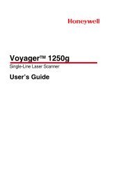
Bar Code Handy Scanner<br />
GT10B-SM / GT11B-SM<br />
GT10B-LM<br />
User's <strong>Manual</strong>
Warning<br />
This is a Class A product. In a domestic environment this product may cause radio interference in which case the<br />
user may be required to take adequate measures.<br />
FCC Regulations<br />
This device complies with Part 15 of the FCC Rules. Operation is subject to the following two conditions:<br />
(1) This device may not cause harmful interference, and<br />
(2) this device must accept any interference received, including interference that may cause undesired<br />
operation.<br />
NOTE: This equipment has been tested and found to comply with the limits for a Class A digital device,<br />
pursuant to Part 15 of the FCC Rules. These limits are designed to provide reasonable protection against harmful<br />
interference when the equipment is operated in a commercial environment. This equipment generates, uses, and<br />
can radiate radio frequency energy and, if not installed and used in accordance with the instruction manual, may<br />
cause harmful interference to radio communications. Operation of this equipment in a residential area is likely to<br />
cause harmful interference in which case the user will be required to correct the interference at his own expense.<br />
DENSO WAVE INCORPORATED does not assume any product liability arising out of, or in connection with,<br />
the application or use of any product, circuit, or application described herein.<br />
If it is judged by DENSO WAVE INCORPORATED that malfunction of the product is due to the product<br />
having been dropped or subjected to impact, repairs will be made at a reasonable charge even within the<br />
warranty period.<br />
Intellectual Property Precaution<br />
DENSO WAVE INCORPORATED ("DENSO WAVE") takes reasonable precautions to ensure its products do<br />
not infringe upon any patent of other intellectual property rights of other(s), but DENSO WAVE cannot be<br />
responsible for any patent or other intellectual property right infringement(s) or violation(s) which arise from (i)<br />
the use of DENSO WAVE's product(s) in connection or in combination with other component(s), product(s),<br />
data processing system(s) or equipment or software not supplied from DENSO WAVE; (ii) the use of DENSO<br />
WAVE's products in a manner for which the same were not intended nor designed; or (iii) any modification of<br />
DENSO WAVE's products by other(s) than DENSO WAVE.<br />
Copyright © DENSO WAVE INCORPORATED, 2008, 2007, 2005, 2004, 2003<br />
All rights reserved. No part of this publication may be reproduced in any form or by any means without permission in<br />
writing from the publisher.<br />
All products and company names mentioned in this manual are trademarks or registered trademarks of their respective<br />
holders.<br />
Specifications are subject to change without prior notice.
Contents<br />
Preface ............................................................................................................................................................................. i<br />
SAFETY PRECAUTIONS.............................................................................................................................................. ii<br />
Care and Maintenance ..................................................................................................................................................... v<br />
Chapter 1 Parts Names and Functions.......................................................................................................................... 1<br />
Chapter 2 Preparation ................................................................................................................................................... 2<br />
2.1 Connecting the Interface Cable to the Scanner........................................................................................... 2<br />
2.2 Connecting the Scanner to Your Computer ................................................................................................ 3<br />
Chapter 3 Reading Bar Codes ...................................................................................................................................... 5<br />
Chapter 4 Customizing the Scanner ............................................................................................................................. 7<br />
Chapter 5 Scanning Control ......................................................................................................................................... 8<br />
5.1 Trigger Switch Control................................................................................................................................ 8<br />
5.2 Software Control ......................................................................................................................................... 9<br />
5.3 Auto Sensing Mode—Automatic Detection of Labels ............................................................................... 11<br />
Chapter 6 Magic Key Control ...................................................................................................................................... 12<br />
Chapter 7 Scanning Functions...................................................................................................................................... 14<br />
7.1 Data Verification Mode............................................................................................................................... 14<br />
7.1.1 Verification setup procedure ................................................................................................................. 14<br />
7.1.2 Verification conditions .......................................................................................................................... 16<br />
7.1.3 Verification result output....................................................................................................................... 17<br />
7.1.4 Output of the master data registered...................................................................................................... 17<br />
7.2 Specifying the Numbers of Digits of Standard 2of5 and Interleaved 2of5 Symbols to Read,<br />
by Scanning Bar Codes ............................................................................................................................... 18<br />
Chapter 8 Data Editing ................................................................................................................................................. 19<br />
8.1 Extracting Data............................................................................................................................................ 19<br />
8.2 Substituting Data ......................................................................................................................................... 20<br />
8.3 Blocksorting Data........................................................................................................................................ 21<br />
8.4 Parenthesizing AIs (Application Identifier) in EAN-128 Data................................................................... 22<br />
8.5 Extracting AI (Application Identifier)-Prefixed Strings from EAN-128 Data........................................... 22<br />
8.6 Data Editing Notes ...................................................................................................................................... 23<br />
8.6.1 Data edit conditions ............................................................................................................................... 23<br />
8.6.2 Rules for data editing............................................................................................................................. 23<br />
8.6.3 AI table................................................................................................................................................... 24<br />
Chapter 9 Beeper, Indicator LED and Vibrator ........................................................................................................... 29<br />
9.1 Beeper.......................................................................................................................................................... 29<br />
9.2 Indicator LED .............................................................................................................................................. 31<br />
9.3 Vibrator........................................................................................................................................................ 32
Chapter 10 Communication.......................................................................................................................................... 33<br />
10.1 RS-232C Interface ....................................................................................................................................... 33<br />
10.2 PS/2 Keyboard Interface.............................................................................................................................. 34<br />
10.3 Communication Format............................................................................................................................... 34<br />
10.3.1 Data transmission format ....................................................................................................................... 34<br />
10.3.2 GTIN format conversion........................................................................................................................ 38<br />
Chapter 11 Parameters and Defaults ............................................................................................................................ 39<br />
(1) Interface to the host ........................................................................................................................ 39<br />
(2) Asynchronous data transmission (RS-232C interface) .................................................................. 39<br />
(3) PS/2 keyboard interface.................................................................................................................. 40<br />
(4) Data transmission format and bar code symbologies..................................................................... 43<br />
(5) Trigger switch control and magic key control................................................................................ 48<br />
(6) Beeper, indicator LED and vibrator ............................................................................................... 49<br />
(7) Data verification mode ................................................................................................................... 50<br />
(8) Notification of a scanning failure under software control ............................................................. 50<br />
(9) Speed-/depth-priority scanning ...................................................................................................... 51<br />
Chapter 12 Bar-Coded Parameter Menu ...................................................................................................................... 52<br />
12.1 Parameter Setting Procedure Using the Bar-Coded Parameter Menu ........................................................ 52<br />
12.2 Bar-Coded Parameter Menu ........................................................................................................................ 53<br />
Menu control (Starting/ending the setting procedure and reverting to defaults) ............................... 53<br />
Communications parameters for the RS-232C interface .................................................................... 54<br />
Communications parameters for the PS/2 keyboard interface............................................................ 56<br />
Data transmission format and bar code symbologies ......................................................................... 61<br />
Trigger switch control and magic key control .................................................................................... 71<br />
Beeper, indicator LED, and vibrator................................................................................................... 72<br />
Data verification mode........................................................................................................................ 73<br />
Notification of a scanning failure under software control.................................................................. 75<br />
Chapter 13 Troubleshooting......................................................................................................................................... 76<br />
Appendix 1 Specifications............................................................................................................................................ 77<br />
Appendix 2 Bar Code Sample Label............................................................................................................................ 80
Preface<br />
This user's manual sets forth the procedures for handling, connecting, operating, and cleaning your bar code handy<br />
scanner. Before you do anything else, study it carefully to make sure that you use the product both correctly and<br />
effectively. Also keep it handy for ready reference.<br />
i
SAFETY PRECAUTIONS<br />
Be sure to observe all these safety precautions.<br />
Please READ through these instructions carefully. They will enable you to use the scanner correctly.<br />
Always keep this manual nearby for speedy reference.<br />
Strict observance of these warnings and cautions is a MUST for preventing accidents that could result in bodily injury<br />
and substantial property damage. Make sure you fully understand all definitions of these terms and symbols given<br />
below before you proceed to the text itself.<br />
Alerts you to those conditions that could cause serious bodily injury or death if the<br />
instructions are not followed correctly.<br />
Alerts you to those conditions that could cause minor bodily injury or substantial property<br />
damage if the instructions are not followed correctly.<br />
Meaning of Symbols<br />
A triangle ( ) with a picture inside alerts you to a warning of danger. Here you see the warning for<br />
electrical shock.<br />
A diagonal line through a circle ( ) warns you of something you should not do; it may or may not have a<br />
picture inside. Here you see a screwdriver inside the circle, meaning that you should not disassemble.<br />
A black circle ( ) with a picture inside alerts you to something you MUST do. This example shows that<br />
you MUST unplug the power cord.<br />
ii
To System Designers:<br />
• When introducing the scanner in those systems that could affect human lives (e.g., medicines<br />
management system), develop applications carefully through redundancy and safety design<br />
which avoids the feasibility of affecting human lives even if a data error occurs.<br />
• Keep the AC adapter from water.<br />
Failure to do so could cause fire or electrical shock.<br />
• Use the dedicated AC adapter only.<br />
Failure to do so could result in fire.<br />
• If the power cord of the AC adapter is damaged (e.g., exposed or broken lead wires), stop<br />
using it and contact your nearest dealer.<br />
Failure to do so could result in a fire or electrical shock.<br />
• Never bring any metals into contact with the terminals in connectors.<br />
Doing so could produce a large current through the scanner, resulting in heat or fire, as well as<br />
damage to the scanner.<br />
• Never use the scanner on the line voltage other than the specified level.<br />
Doing so could cause the scanner to break or burn.<br />
• Do not use the scanner where any inflammable gases may be emitted.<br />
Doing so could cause fire.<br />
• Do not scratch, modify, bend, twist, pull, or heat the power cable of the AC adapter. Do not<br />
place heavy material on the cable or allow the cable to get pressed under heavy material.<br />
Doing so could break the cable, resulting in a fire.<br />
• Do not subject the scanning window of the scanner to direct sunlight for extended periods.<br />
Doing so could damage the scanner, resulting in a fire.<br />
• If smoke, abnormal odors or noises come from the scanner, immediately switch off the host<br />
computer, disconnect the AC adapter and the interface cable, and contact your nearest dealer.<br />
Failure to do so could cause fire or electrical shock.<br />
• If foreign material or water gets into the scanner, immediately unplug the AC adapter and the<br />
interface cable, and contact your nearest dealer.<br />
Failure to do so could cause fire or electrical shock.<br />
• If you drop the scanner so as to affect the operation or damage its housing, switch off the host<br />
computer, unplug the AC adapter and the interface cable, and contact your nearest dealer.<br />
Failure to do so could cause fire or electrical shock.<br />
iii
Never<br />
disassemble<br />
• Never disassemble or modify the scanner; doing so could result in an accident such as break or<br />
fire.<br />
Doing so could result in a fire or electrical shock.<br />
• Do not put the scanner on an unstable or inclined plane.<br />
The scanner may drop, creating injuries.<br />
• Never put the scanner in places where there are excessively high temperatures, such as inside<br />
closed-up automobiles, or in places exposed to direct sunlight.<br />
Doing so could affect the housing or parts, resulting in a fire.<br />
• Avoid using the scanner in extremely humid areas, or where there are drastic temperature<br />
changes.<br />
Moisture will get into the scanner, resulting in malfunction, fire or electrical shock.<br />
• Do not place the scanner anyplace where it may be subjected to oily smoke or steam, e.g., near<br />
a cooking range or humidifier.<br />
Doing so could result in a fire or electrical shock.<br />
• Never cover or wrap up the scanner or AC adapter in a cloth or blanket.<br />
Doing so could cause the unit to heat up inside, deforming its housing, resulting in a fire.<br />
Always use the scanner and AC adapter in a well-ventilated area.<br />
• Keep the power cable of the AC adapter from any heating equipment.<br />
Failure to do so could melt the sheathing, resulting in a fire or electrical shock.<br />
• Do not insert or drop foreign materials such as metals or anything inflammable through the<br />
openings (vents or scanning window) into the scanner.<br />
Doing so could result in a fire or electrical shock.<br />
• Do not scratch or modify the scanner or its interface cable. Do not bend, twist, pull, or heat the<br />
cable.<br />
Doing so could damage the scanner or its interface cable, creating a fire hazard.<br />
• Do not put heavy material on the scanner or its interface cable, or allow the cable to get pressed<br />
under heavy material.<br />
• Do not look into the light source from the scanning window or do not point the scanning window<br />
at other people's eyes.<br />
Eyesight may be damaged by direct exposure to this light.<br />
• Do not use the scanner if your hands are wet or damp.<br />
Doing so could result in an electrical shock.<br />
• Never use chemicals or organic solvents such as benzene and thinner to clean the housing. Do<br />
not apply insecticide to the scanner.<br />
Doing so could result in a marred or cracked housing, electrical shock or fire.<br />
• Do not use the scanner with anti-slip gloves containing plasticizer.<br />
The scanner housing may be broken, creating injuries, electrical shock, or fire.<br />
iv
• When disconnecting the AC adapter from the wall socket, hold the AC adapter body not the<br />
power cable.<br />
The power cable may be broken, resulting in a burnt AC adapter, electrical shock, or fire.<br />
• If the interface cable is damaged (e.g., exposed or broken lead wires), stop using it and contact<br />
your nearest dealer.<br />
Failure to do so could result in a fire or electrical shock.<br />
• If you are not using the scanner for a long time, be sure to unplug the AC adapter from the wall<br />
socket for safety.<br />
Failure to do so could result in a fire.<br />
• During electrical storm activity, always unplug the AC adapter from the wall socket.<br />
Exposure to power surges could result in a damaged scanner or fire.<br />
• When taking care of the scanner, unplug the AC adapter from the wall socket for safety.<br />
Failure to do so could result in an electrical shock.<br />
• Do not drop the scanner.<br />
The scanner housing may be broken, creating injuries.<br />
Using the scanner whose housing is broken could result in smoke or fire.<br />
Unplug the AC adapter from the wall socket and contact your nearest dealer.<br />
Care and Maintenance<br />
Dust or dirt accumulating on the clear plate of the bar code reading window will affect reading performance. If you<br />
use the scanner in dusty areas, therefore, periodically check the clear plate and clean it if dusty.<br />
• To clean the plate, first blow the dust away with an airbrush. Then wipe the plate with a cotton swab or the similar<br />
soft one gently.<br />
• If sand or hard particles have accumulated, never rub the plate; doing so will scratch or damage it. Blow the<br />
particles away with an airbrush or a soft brush.<br />
Limited <strong>Warranty</strong> on Software Products<br />
In no event will DENSO WAVE be liable for direct, indirect, special, incidental, or consequential damages (including<br />
imaginary profits or damages resulting from interruption of operation or loss of business information) resulting from<br />
any defect in the software or its documentation or resulting from inability to apply the software or its documentation.<br />
v
Chapter 1 Parts Names and Functions<br />
Reading window<br />
Point this at the bar code<br />
to read.<br />
Trigger switch<br />
Press this to read a bar code.<br />
The following trigger switch operating<br />
modes are available:<br />
• Auto-off mode 1<br />
• Auto-off mode 2<br />
• Momentary switching mode 1<br />
• Momentary switching mode 2<br />
• Continuous reading mode<br />
(The factory default is momentary<br />
switching mode 1.)<br />
In addition, the auto sensing mode is<br />
also available for automatic trigger<br />
operation.<br />
Refer to Chapter 5 for details.<br />
Interface cable<br />
There are two types of<br />
interface cables available.<br />
• RS-232C interface<br />
• PS/2 keyboard interface<br />
1<br />
Indicator LED<br />
This turns blue after a successful read and red if<br />
there is an error.<br />
(Refer to Chapter 9 for details.)<br />
Magic key<br />
This key functions as an auxiliary key for<br />
reads, data transfers, and the like. These<br />
auxiliary functions include:<br />
• Illumination LED switching function<br />
• Data retransfer function<br />
• Specific character transfer function<br />
• Ready/standby switching function<br />
• Auto sensing mode switching function<br />
• Continuous reading mode switching<br />
function<br />
(The factory configuration assigns none<br />
of these functions to this key.)<br />
Refer to Chapter 6 for details.
Chapter 2 Preparation<br />
2.1 Connecting the Interface Cable to the Scanner<br />
(1) Pull the connector cover of the interface cable off its connector as shown below.<br />
(2) Plug the interface cable connector into the connector located in the bottom of the scanner.<br />
Note: As shown below, hold the scanner body, align the ▼ mark on the cable connector with that on the scanner,<br />
and fully insert the interface cable connector.<br />
Connector cover<br />
Interface cable connector<br />
Scanner<br />
(3) Align the two bosses on the connector cover with cutouts in the scanner body, fit the connector cover into the<br />
scanner, and turn it clockwise to lock it.<br />
Cutout<br />
Boss<br />
▼ mark<br />
Connector cover<br />
2<br />
▼ mark<br />
Connector cover<br />
Turn the cover until the<br />
bosses come to be<br />
horizontal.
2.2 Connecting the Scanner to Your Computer<br />
Using the RS-232C interface<br />
(1) Connect the RS-232C interface cable to your computer.<br />
Scanner<br />
AC adapter<br />
RS-232C interface cable<br />
(2) Plug the AC adapter into the DC power jack provided in the cable connector.<br />
(3) If the interface setting has been changed from the RS-232C interface (factory default) to the PS/2 keyboard<br />
interface, change it back to the RS-232C interface by scanning the following bar code:<br />
RS-232C interface<br />
Note: When disconnecting the interface cable or DC power jack, hold the connector housings not the cables. Pulling<br />
cables will result in breaks.<br />
Note: Avoid connecting and disconnecting of connectors all if possible. Doing so may result in weak contact.<br />
Note: Be sure to use the adapter exclusively designed for the scanner.<br />
3
Using the PS/2 keyboard interface<br />
Note: Before proceeding to the connection procedure, be sure to switch off your computer.<br />
(1) The PS/2 keyboard interface cable is a Y-letter type having two connectors. Connect them to your computer and<br />
its keyboard as shown below.<br />
For a notebook or other computer with no external keyboard connected, simply plug the cable into the external<br />
keyboard connector.<br />
PS/2 keyboard interface cable<br />
Scanner<br />
Connector for computer<br />
(male)<br />
Connector for keyboard (female)<br />
(2) When you use the scanner first after delivery, change the interface setting to the PS/2 keyboard interface from the<br />
RS-232C interface (factory default) by scanning the following bar code:<br />
PS/2 keyboard interface<br />
(3) Select the keyboard connection type from "With external keyboard (default)," "Without external keyboard," and<br />
"With external numeric keypad" by using the bar-coded parameter menu in Chapter 12. (For details about the<br />
keyboard connection type, refer to page 56)<br />
(4) If you have modified the scanner settings in step (2) or (3) above, restart your computer.<br />
Note: Do not input data from the scanner and keyboard simultaneously. The scanner cannot accept such entry normally.<br />
4
Chapter 3 Reading Bar Codes<br />
(1) Press the trigger switch to turn on the illumination LED and prepare the scanner for reading.<br />
Note: This step is not required for the continuous reading and auto sensing modes (see Section 5.3).<br />
(2) Align the scanner over the center of the target bar code so that the illumination longitudinally scans the center of<br />
the bar code.<br />
(3) Wait for the indicator LED to turn blue and the beeper to sound, indicating a successful read.<br />
Note: The effective scan range is less than the full illumination range.<br />
The effective scan range depends on the model and the distance from the scanner to the target.<br />
GT10B-SM/GT11B-SM: approximately 10 cm (3.94") for a scan distance of 7 cm (2.76")<br />
GT10B-LM: approximately 17 cm (6.69") for a scan distance of 18 cm (7.09")<br />
Note: Having more than one bar code within the field of view either causes the read to fail or produces multiple<br />
input.<br />
Note: Bar code orientation (right side up or upside down) does not matter as long as the margins are well within<br />
the field of view.<br />
Note: It is sometimes necessary to vary the scanning angle or distance to eliminate reflections of the illumination<br />
and ambient light off highly reflective labels.<br />
Scanning modes<br />
Illumination<br />
Regular read mode Successful completion of read-in produces data transfer.<br />
Data verification mode The scanner transfers only data that matches a predefined list of acceptable bar codes.<br />
(Refer to Chapter 7 for details.)<br />
Speed-/depth-priority scanning<br />
Speed-priority The scanner gives priority to reducing the time spent decoding bar code data.<br />
Depth-priority The scanner gives priority to expanding the scan range.<br />
For details, refer to Appendix 1.<br />
Effective<br />
scan range<br />
Trigger switch<br />
5<br />
Scan distance<br />
GT10B-SM/GT11B-SM: 7 cm (2.76")<br />
GT10B-LM: 18 cm (7.09")<br />
Indicator LED
Reading RSS-14 Stacked and RSS-14 Stacked Omnidirectional symbols<br />
The scanner reads RSS-14 Stacked and RSS-14 Stacked Omnidirectional symbols in two steps. In the 1st step, it scans<br />
either one of the 1st and 2nd rows of the target symbol and accumulates the data in itself. In the 2nd step, it scans the<br />
remaining row, edits the 1st and 2nd row data read, and then sends the data to the host.<br />
To inform the user that the 1st or 2nd row data has accumulated in the scanner, the scanner emits a one-shot beep by<br />
default. Upon completion of a successful read of the remaining row, the scanner emits a short beep just as upon<br />
completion of a read of any other type of bar code.<br />
To discard the accumulated data halfway through a sequence of scanning, turn off the illumination LED. In the<br />
continuous reading mode or auto sensing mode, however, move the illumination away from the target symbol.<br />
6
Chapter 4 Customizing the Scanner<br />
You can customize the scanner by modifying communications, bar code type, and other scanner parameters with the<br />
bar-coded parameter menu or the configuration software ScannerSetting*. These parameters retain their settings even<br />
when the power is off.<br />
(1) Scanning parameter setting bar codes from the bar-coded parameter menu by pressing the trigger switch.<br />
(The bar-coded parameter menu is given in Chapter 12.)<br />
(2) Using the configuration software (ScannerSetting)* in your computer. (The software also offers batch-process<br />
bar code printouts for read by scanners in the field.)<br />
* Registered users can download the configuration software (ScannerSetting) from QBdirect, their customer support<br />
section on the Denso Wave website at no extra charge.<br />
For further details on QBdirect or to register, visit the following URL.<br />
http://www.qbdirect.net<br />
7
Chapter 5 Scanning Control<br />
Two types of scanning controls are available--Trigger switch control and Software control.<br />
Trigger switch control: Pressing the trigger switch readies the scanner for scanning.<br />
Software control: Instead of pressing the trigger switch, you send control commands from the host computer via the<br />
RS-232C interface to ready the scanner for scanning or put the scanner on standby.<br />
5.1 Trigger Switch Control<br />
Pressing the trigger switch turns on the illumination LED and readies the scanner for scanning. The scanner supports<br />
the following five trigger switch operating modes. Select the one that best meets your needs using the bar-coded<br />
parameter menu or the configuration software (ScannerSetting).<br />
(1) Auto-off mode 1<br />
Holding down the trigger switch lights the illumination LED for the specified period (selectable from 1 to 5 seconds in<br />
one second increments with the configuration software (ScannerSetting)), during which the scanner is ready to scan.<br />
When a bar code is read successfully or the specified period has elapsed, the illumination LED goes off and the<br />
scanner switches to standby.<br />
(2) Auto-off mode 2<br />
If you press the trigger switch, the illumination LED lights for approx. 5 seconds during which the scanner is ready to<br />
scan, regardless of whether a bar code is read successfully or the trigger switch is released.<br />
After a bar code is read successfully, the ready-to-scan state further continues for approx. 5 seconds.<br />
If the scanner is left without scanning operation for approx. 5 seconds, it turns off the illumination LED and switches<br />
to standby.<br />
(3) Momentary switching mode 1 (Factory default)<br />
Only while you hold down the trigger switch, the illumination LED lights and the scanner is ready to scan.<br />
When you release the trigger switch or a bar code is read successfully, the illumination LED goes off and the scanner<br />
switches to standby.<br />
(4) Momentary switching mode 2<br />
Only while you hold down the trigger switch, the illumination LED lights and the scanner is ready to scan, regardless<br />
of whether a bar code is read successfully.<br />
When you release the trigger switch, the illumination LED goes off and the scanner switches to standby.<br />
(5) Continuous reading mode<br />
When you turn the scanner on, the scanner lights the illumination LED and becomes ready to scan. The scanner<br />
ignores all trigger switch input.<br />
Note: When you are setting parameters using the bar-coded parameter menu, the scanner is always in the<br />
momentary switching mode 1 regardless of the trigger switch operating mode selected.<br />
Note: The trigger switch is disabled as long as the scan lock (see Section 7.1.3) is in effect in the data verification<br />
mode.<br />
8
5.2 Software Control<br />
You can control the scanner by sending scanning control commands from the host computer via the RS-232C interface,<br />
instead of pressing the trigger switch.<br />
Scanning control commands include R, READON, LON, RC, Z, READOFF and LOFF and they are restricted by the<br />
trigger switch operating mode, as listed below. In momentary switching mode 1, for example, the RC command is<br />
invalid. In auto-off mode 2 and momentary switching mode 2, all of these commands are invalid.<br />
(√ : Command valid)<br />
Commands Description<br />
R,<br />
READON,<br />
LON<br />
RC<br />
Z,<br />
READOFF,<br />
LOFF<br />
Ready-to-scan commands<br />
Upon receipt of one of these commands,<br />
the scanner turns on the illumination<br />
LED and becomes ready to scan.<br />
Standby commands<br />
Upon receipt of one of these commands,<br />
the scanner turns off the illumination<br />
LED and goes on standby.<br />
Auto-off<br />
mode 1<br />
9<br />
Trigger switch operating modes<br />
Auto-off<br />
mode 2<br />
Momentary<br />
switching<br />
mode 1<br />
Momentary<br />
switching<br />
mode 2<br />
Continuous<br />
reading mode<br />
√ -- √ -- √<br />
-- -- -- -- √<br />
-- -- √ -- √<br />
Each of these commands should be enclosed with a header and terminator for transmission according to the<br />
communications conditions of the scanner.<br />
Note: When the scanner is ready to scan with an R, READON or LON command, pressing the trigger switch<br />
cancels the command control, producing the operation specified for the trigger switch.<br />
Notification of a scanning failure<br />
If the scanner fails to read a bar code and switches to standby in auto-off mode 1 or momentary switching mode 1, it<br />
can send the following two types of notification data (cancel or error) to the host computer.<br />
- CAN (18h)<br />
- ERROR (with header and terminator)<br />
Control scheme<br />
(1) Auto-off mode 1 or momentary switching mode 1<br />
Successful read<br />
Command input (RxD)<br />
Bar code<br />
Illumination LEDs<br />
Data output (TxD)<br />
Ready-to-scan command<br />
Bar code data
Failure read<br />
• Auto-off mode 1<br />
Command input (RxD)<br />
Bar code<br />
Illumination LEDs<br />
Data output (TxD)<br />
• Momentary switching mode 1<br />
Command input (RxD)<br />
Bar code<br />
Illumination LEDs<br />
Data output (TxD)<br />
(2) Continuous reading mode<br />
Ready-to-scan command<br />
1 to 5 sec.<br />
Failure notification<br />
Ready-to-scan command<br />
Switching to the ready-to-scan state with an R, READON or LON command<br />
Command input (RxD)<br />
Bar code<br />
Illumination LEDs<br />
Data output (TxD)<br />
Standby command<br />
Switching to the ready-to-scan state with an RC command<br />
Command input (RxD)<br />
Bar code<br />
Illumination LEDs<br />
Data output (TxD)<br />
Standby command<br />
Standby command<br />
10<br />
Failure notification<br />
Bar code data<br />
Bar code data<br />
Ready-to-scan command<br />
Ready-to-scan command
5.3 Auto Sensing Mode—Automatic Detection of Labels<br />
In auto sensing mode, bringing a bar code label within the scan range of the reading window turns on the illumination<br />
LED and starts the scanner reading the bar code. No trigger switch operation is required. Use this mode when the<br />
scanner is stationary to a stand and a bar code label is moved.<br />
The illumination LED comes on when you bring a bar code label within the designated range or move a bar code label<br />
within the same range. The LED goes off when a bar code label is moved away from the range or stays within the<br />
range without move for approx. 5 seconds.<br />
The scanner offers a choice of three sensitivity levels for responding to bar codes. Switch to a higher sensitivity level<br />
if the illumination LED will not come on when a bar code is brought into the range, for example.<br />
Note: Even if you do not bring a bar code label within the scan range, the illumination LED may come on when<br />
the ambient level of light changes or any shadows move within the scan range.<br />
Note: Given below is a guide for scanning EAN-13 symbols in auto sensing mode under these conditions: At the<br />
center of the effective scan range and at the ambient illuminance of 500 lux or higher.<br />
GT10B-SM/GT11B-SM: Scan distance of approx. 21 cm (8.27")<br />
GT10B-LM: Scan distance of approx. 40 cm (15.75")<br />
Note: It is sometimes necessary to vary the scanning angle or distance to eliminate reflections of the illumination<br />
and ambient light off highly reflective labels.<br />
11
Chapter 6 Magic Key Control<br />
The magic key can act as an auxiliary key for scanning or data transfer. You can assign any of the following five<br />
functions or no function at all to the magic key. Select the function that best meets your needs using the bar-coded<br />
parameter menu or the configuration software (ScannerSetting).<br />
(1) Illumination switching function<br />
Pressing the magic key alternately turns the illumination LED on and off. Note, however, that turning on the LED<br />
does not make the scanner ready to scan. That requires pressing the trigger switch.<br />
The scanner automatically turns off the illumination LED after approximately 3 minutes without detecting completion<br />
of a scanning operation.<br />
The scanner ignores magic key input if the trigger switch operating mode is continuous read or auto sensing mode.<br />
The illumination<br />
LED comes on.<br />
Press the magic key. Press the trigger switch.<br />
(2) Data retransfer function<br />
Pressing the magic key resends the preceding data. Note, however, that the scanner ignores such requests if there is no<br />
such data available--that is, you have turned off the power since the last read operation.<br />
(3) Specific character transfer function<br />
Pressing the magic key transfers a character string (max. 10 bytes) specified with the configuration software<br />
(ScannerSetting).<br />
(4) Ready/standby switching function<br />
When the trigger switch is in the continuous reading mode, pressing the magic key switches the scanner between<br />
ready-to-scan (illumination LED ON) and standby (illumination LED OFF).<br />
(5) Auto sensing mode switching function<br />
Pressing the magic key toggles between the auto sensing mode and the currently selected trigger switch operating<br />
mode.<br />
(6) Continuous reading mode switching function<br />
Pressing the magic key toggles between the continuous reading mode and the currently selected trigger switch<br />
operating mode.<br />
(7) No function (Disable)<br />
If no function has been assigned to the magic key, pressing the key produces no operation.<br />
12<br />
Completion of scanning
The following table lists the relationship between the magic key functions and trigger switch operating modes. (It<br />
applies to both the regular read mode and data verification mode.) The "--" indicates that the scanner ignores the<br />
magic key functions assigned. In auto-off mode 1, for example, the ready/standby switching function is ignored.<br />
Magic key functions<br />
Auto-off mode<br />
1<br />
Auto-off mode<br />
2<br />
Trigger switch operating modes<br />
13<br />
Momentary<br />
switching<br />
mode 1<br />
Momentary<br />
switching<br />
mode 2<br />
Continuous<br />
reading mode<br />
Auto sensing<br />
mode<br />
Illumination switching<br />
function<br />
√ √ √ √ -- --<br />
Data retransfer function √ √ √ √ √ √<br />
Specific character transfer<br />
function<br />
√ √ √ √ √ √<br />
Ready/standby switching<br />
function<br />
-- -- -- -- √ --<br />
Auto sensing mode<br />
switching function<br />
√ √ √ √ √ --<br />
Continuous reading mode<br />
switching function<br />
√ √ √ √ -- √<br />
No function √ √ √ √ √ √
Chapter 7 Scanning Functions<br />
7.1 Data Verification Mode<br />
The data verification mode verifies the bar code data read against the master data stored in the scanner and reports the<br />
match status with data output.<br />
Data verification read is available in two types--"n-point verification" and "2-point verification."<br />
Selecting the n-point verification requires registering master data only one time for 1:n verification. The scanner<br />
verifies all bar code data read after registration against the master data.<br />
The 2-point verification refers to 1:1 verification. Selecting it requires registering master data each time preceding bar<br />
code scanning. After registration of master data, the scanner reads a bar code, verifies the bar code data read against<br />
the master data and then becomes ready to register new master data. This way, the 2-point verification read alternately<br />
repeats master data registration and bar code scanning.<br />
The master data registration procedure is different in n-point and 2-point verification reads. (See Section 7.1.1.)<br />
The verification parameters can be specified using the bar-coded parameter menu or configuration software<br />
(ScannerSetting). After specifying them, scan a master bar code, and the scanner becomes capable of data verification<br />
read.<br />
7.1.1 Verification setup procedure<br />
n-point verification read<br />
After one-time registration of master data, the scanner verifies all bar code data read after registration against the<br />
master data.<br />
- Switch to the data verification mode.<br />
- Specify the verification parameters<br />
(verification conditions and result<br />
output ways).<br />
↓<br />
Scan a master bar code to register.<br />
(Registration of master data)<br />
↓<br />
Scan bar codes.<br />
Note: For what clears the registered master data, see the next page.<br />
Use the bar-coded parameter menu or configuration software.<br />
The indicator LED flashes in red, indicating that no master bar code is<br />
registered in the scanner.<br />
Hold down the magic key to light the indicator LED in green. Keep the<br />
magic key held down and press the trigger switch to scan a master bar<br />
code.<br />
After registration of master data, the indicator LED goes off.<br />
Use the scanner to scan a target bar code. The scanner verifies the bar<br />
code read against the master data registered and then outputs the result.<br />
After a successful read, the indicator LED lights in blue.<br />
14
2-point verification read<br />
After registration of master data, the scanner reads a bar code, verifies the bar code data read against the master data<br />
and then becomes ready to register new master data.<br />
- Switch to the data verification mode.<br />
- Specify the verification parameters<br />
(verification conditions, result output<br />
ways, and verification retry after<br />
mismatch*).<br />
↓<br />
Scan a master bar code to register.<br />
(Registration of master data)<br />
↓<br />
Scan bar codes.<br />
Use the bar-coded parameter menu or configuration software.<br />
The indicator LED lights in green, indicating that the scanner is ready<br />
to register master data.<br />
Press the trigger switch to scan a master bar code.<br />
After registration of master data, the indicator LED goes off.<br />
Use the scanner to scan a target bar code. The scanner verifies the bar<br />
code read against the master data registered and then outputs the<br />
result.<br />
After a successful read, the indicator LED lights in green, indicating<br />
that the scanner is ready to register new master data.<br />
*Verification retry after mismatch in 2-point verification<br />
The 2-point verification read provides the "Verification retry after mismatch" option that retries verification against<br />
the same master data. Enabling this option readies the scanner not for registering new master data but for reading a bar<br />
code again if the verification result is a mismatch.<br />
Disabling this option readies the scanner for registering new master data after bar code reading, no matter what the<br />
verification result is.<br />
Note: Any of the following events clears the master data stored in the scanner.<br />
- Customizing the scanner by modifying the parameters with the configuration software (ScannerSetting) or<br />
batch-process bar code symbols.<br />
- Modifying the "verification start position in data verification mode" or "number of characters to verify, starting<br />
from the verification start position" setting with the bar-coded parameter menu.<br />
- The scanner power is turned off due to the removal/replacement of the battery cartridge or the low battery.<br />
15
7.1.2 Verification conditions<br />
You can set a verification starting position and the number of characters to check.<br />
- Starting position: The choices are 1st through 7th characters.<br />
- Number of characters: The choices are 1 through 7 and everything following the starting position (up to a<br />
maximum of 32 characters).<br />
For example, you can specify all characters or particular characters of bar code data to check as shown below.<br />
Master data<br />
12345601<br />
Bar code data readable<br />
Master data<br />
12345601<br />
12345601<br />
Bar code data readable<br />
01347803<br />
Verification conditions: All characters to check<br />
To check all characters as underlined at left, for example, set the following:<br />
- Starting position: 1st character<br />
- Number of characters: All characters<br />
Max. 32 bytes of bar code data can be verified.<br />
Verification conditions: Particular characters to check<br />
To check particular characters as underlined at left, for example, set the<br />
following:<br />
- Starting position: 3rd character<br />
- Number of characters: 2 characters<br />
Note: If the bar code type (symbology) of data read is different from that of the master data, the verification results<br />
in a mismatch even if those data matches.<br />
16
7.1.3 Verification result output<br />
(1) Report of match/mismatch status<br />
You can select any of the following report types by using the bar-coded parameter menu or configuration software<br />
(ScannerSetting). Selecting "Disable transmission" reports nothing.<br />
Setting If there is a match: If there is a mismatch:<br />
1 Disable bar code data transmission. Disable bar code data transmission.<br />
2 Enable bar code data transmission. Disable bar code data transmission.<br />
3 Enable bar code data transmission. Enable NG transmission.<br />
4 Enable OK transmission. Enable NG transmission.<br />
(2) Beeper, indicator LED, and vibrator<br />
You can check whether the verification result is a match or mismatch, with the beeper, indicator LED and vibrator.<br />
When the beeper, indicator LED and vibrator are enabled, they act as listed below.<br />
Beeper Indicator LED<br />
Vibrator<br />
"OK" vibrations "NG" vibrations<br />
If there is a match: Emits a short beep. Lights in blue. Operates. --<br />
If there is a mismatch: Emits a long beep. Lights in red. -- Operates.<br />
(3) Scan lock<br />
The scan lock function locks the scanner on standby if the verification result is a mismatch. You can enable or disable<br />
this function with the bar-coded parameter menu or configuration software (ScannerSetting).<br />
Once the scanner is locked, it switches to standby regardless of the current trigger switch control selected. The scanner<br />
remains on standby even if the trigger switch is pressed or a ready-to-scan command (R, READON or LON) is<br />
received.<br />
Pressing the magic key or turning off the power releases the scan lock.<br />
7.1.4 Output of the master data registered<br />
Scanning the "Output master data" bar code given below lets the scanner output the master data registered in the<br />
verification setup procedure.<br />
Note: In the 2-point verification read, the scanner cannot read this bar code, so it cannot output master data.<br />
Output master data<br />
17
7.2 Specifying the Numbers of Digits of Standard 2of5 and Interleaved 2of5 Symbols to<br />
Read, by Scanning Bar Codes<br />
You can specify the numbers of digits of Standard 2of5 and Interleaved 2of5 symbols to read.<br />
First enable the parameter "specification of the number of digits by bar code scanning" by using the bar-coded<br />
parameter menu or configuration software. Then scan Standard 2of5 or Interleaved 2of5 symbols. The numbers of<br />
digits of symbols scanned first and second (after you enable the parameter or turn the scanner on) will be registered in<br />
the memory.<br />
After the registration, the scanner can read only Standard 2of5 or Interleaved 2of5 symbols having either of those<br />
specified numbers of digits.<br />
(Example)<br />
123457<br />
1234567895<br />
987653<br />
98765430<br />
Specifying the number of digits readable<br />
First scan: 6-digit Interleaved 2of5 symbol<br />
→ Just the bar code type and the number of digits will be stored in the scanner.<br />
The code data will be sent.<br />
Second scan: 10-digit Interleaved 2of5 symbol<br />
→ Just the bar code type and the number of digits will be stored in the scanner.<br />
The code data will be sent.<br />
After that, 6-digit and 10-digit Interleaved 2of5 symbols only can be read.<br />
Scanning after setting the number of digits readable<br />
6-digit Interleaved 2of5 bar code<br />
→ This bar code can be read.<br />
8-digit Interleaved 2of5 bar code<br />
→ This bar code cannot be read.<br />
18
Chapter 8 Data Editing<br />
The scanner can edit bar code data read in the format specified with the configuration software (ScannerSetting) and<br />
transfer it to the host computer.<br />
The format specification parameters retain their settings until the configuration software (ScannerSetting) or<br />
bar-coded parameter menu sets "All defaults."<br />
8.1 Extracting Data<br />
The scanner extracts a part of bar code data read according to the extraction conditions--"Specified number of digits<br />
from head position," "Specified number of digits from tail position," "From the specified start to tail positions," and<br />
"From the specified start to end positions.<br />
The following sample bar code and scanner settings output data as listed below depending upon the extraction<br />
conditions.<br />
- Bar code sample<br />
Bar code type: Code 128, Data read: 1234567890<br />
- Scanner settings<br />
Header: STX, Terminator: ETX, Prefix/Suffix: None, Code ID mark: Type 1,<br />
Transmission of number of digits: 2 digits<br />
(1) Extracting the specified number of digits of data from head position<br />
The number of digits must be within the range from 1 to 99. If the number of digits in bar code data read is less than<br />
the one specified, an error occurs.<br />
(Example)<br />
Number of digits Output data<br />
3 digits [STX]K03123[ETX]<br />
8 digits [STX]K0812345678[ETX]<br />
12 digits Error<br />
(2) Extracting the specified number of digits of data from tail position<br />
The number of digits must be within the range from 1 to 99. For example, three digits of data from the tail position<br />
contain "890." If the number of digits in bar code data read is less than the one specified, an error occurs.<br />
(Example)<br />
Number of digits Output data<br />
3 digits [STX]K03890[ETX]<br />
8 digits [STX]K0834567890[ETX]<br />
12 digits Error<br />
19
(3) Extracting data from the specified start to tail positions<br />
The start position must be within the range from the 2nd to 99th digits. If the number of digits in bar code data read<br />
does not reach the specified start position, an error occurs.<br />
(Example)<br />
Start position Output data<br />
3rd position [STX]K0834567890[ETX]<br />
8th position [STX]K03890[ETX]<br />
12th position Error<br />
(4) Extracting data from the specified start to end positions<br />
The start and end positions must be within the range from 2nd to 99th digits each. The end position must be equal to<br />
or greater than the start position. If the number of digits in bar code data read does not reach the specified start or end<br />
position, an error occurs.<br />
(Example)<br />
Start position End position Output data<br />
3rd position 7th position [STX]K0534567[ETX]<br />
8th position 10th position [STX]K03890[ETX]<br />
10th position 11th position Error<br />
8.2 Substituting Data<br />
The scanner searches the specified string (max. 10 characters long) in bar code data read, starting from the specified<br />
start position (the head to the 10th position) to the end. If the bar code data contains the specified string, the scanner<br />
substitutes it with the specified substitution string (max. 3 characters long) and transfers it according to the<br />
substitution conditions--"Transferring the substituted element string only," "Transferring the substituted element string<br />
+ bar code data," and "Transferring the substituted full string."<br />
The following sample bar code and scanner settings output data as listed below depending upon the substitution<br />
conditions.<br />
- Bar code sample<br />
Bar code type: Code 128, Data read: 1234567890<br />
- Scanner settings<br />
Header: STX, Terminator: ETX, Prefix/Suffix: None, Code ID mark: Type 1,<br />
Transmission of number of digits: 2 digits<br />
(1) Transferring the substituted element string only<br />
If the bar code data contains the specified substitution string within the specified search area, the scanner transfers the<br />
substituted element string only.<br />
(Example)<br />
Search start position Search string Substitution string Output data<br />
2nd position 456 A [STX]K01A[ETX]<br />
5th position 890 XYZ [STX]K03XYZ[ETX]<br />
9th position 890 XYZ Error<br />
20
(2) Transferring the substituted element string<br />
If the bar code data contains the specified substitution string within the specified search area, the scanner transfers the<br />
substituted element string followed by the bar code data read.<br />
(Example)<br />
Search start position Search string Substitution string Output data<br />
2nd position 456 A [STX]K11A1234567890[ETX]<br />
5th position 890 XYZ [STX]K13XYZ1234567890[ETX]<br />
9th position 890 XYZ Error<br />
(3) Transferring the substituted full string<br />
If the bar code data contains the specified substitution string within the specified search area, the scanner substitutes<br />
the search string with the substitution string and transfers the full string. If it contains two or more search strings, only<br />
the first one is substituted.<br />
(Example)<br />
Search start position Search string Substitution string Output data<br />
2nd position 456 A [STX]K08123A7890[ETX]<br />
5th position 890 XYZ [STX]K101234567XYZ[ETX]<br />
9th position 890 XYZ Error<br />
8.3 Blocksorting Data<br />
The scanner splits bar code data read into a maximum of 5 blocks at the specified split positions and sorts those blocks<br />
in the specified order.<br />
The split position must be specified by the number of digits from the head of bar code data. Specifying the number of<br />
digits exceeding that in the bar code data results in an error.<br />
The following sample bar code and scanner settings output data as listed below depending upon the sorting conditions.<br />
- Bar code sample<br />
Bar code type: Code 128, Data read: 1234567890<br />
- Scanner settings<br />
Header: STX, Terminator: ETX, Prefix/Suffix: None, Code ID mark: Type 1,<br />
Transmission of number of digits: 2 digits<br />
(Example)<br />
Split position Order of blocks Output data<br />
3rd position, 8th position Block 2, 1, 3 [STX]K104567812390[ETX]<br />
3rd position, 8th position Block 1, 3 [STX]K0512390[ETX]<br />
21
8.4 Parenthesizing AIs (Application Identifier) in EAN-128 Data<br />
The scanner parenthesizes all AIs contained in EAN-128 data read and transfers the data. (For the definition of AIs,<br />
see Section 8.6.3.)<br />
The following sample bar code and scanner settings output data with AIs parenthesized as listed below.<br />
- Bar code sample<br />
Bar code type: EAN-128, Data read: 0194901234567894110308081303081017040208<br />
- Scanner settings<br />
Header: STX, Terminator: ETX, Prefix/Suffix: None, Code ID mark: Type 1,<br />
Transmission of number of digits: 2 digits<br />
(Example)<br />
Output data<br />
[STX]W48(01)94901234567894(11)030808(13)030810(17)040208[ETX]<br />
8.5 Extracting AI (Application Identifier)-Prefixed Strings from EAN-128 Data<br />
The scanner extracts element strings prefixed with the specified AIs (up to three types of AIs) and separates them with<br />
the specified delimiters (selectable from headers/terminators, commas, and tabs) instead of AIs to transfer them. (For<br />
the definition of AIs, see Section 8.6.3.)<br />
The following sample bar code and scanner settings output data as listed below depending upon the AI conditions.<br />
- Bar code sample<br />
Bar code type: EAN-128, Data read: (01)94901234567894(11)030808(13)030810(17)040208<br />
- Scanner settings<br />
Header: STX, Terminator: ETX, Prefix/Suffix: None, Code ID mark: Type 1,<br />
Transmission of number of digits: 2 digits<br />
(1) Header/terminator<br />
Specifying a header/terminator as a delimiter prefixes a header and suffixes a terminator to each element string<br />
separated.<br />
A prefix, suffix, the number of digits, and code ID mark can be also added to each element string if their transmissions<br />
are enabled. The number of digits is that in each element string after editing.<br />
(Example)<br />
AIs specified Output data<br />
AI1=01, AI2=17 [STX]W1494901234567894[ETX] [STX]W06040208[ETX]<br />
(2) Comma<br />
Specifying a comma as a delimiter outputs comma-delimited data. No comma follows the tail of the data.<br />
A header and terminator are added to the full string. A prefix, suffix, the number of digits, and code ID mark can be<br />
also added to the full string if their transmissions are enabled. The number of digits is that in the full string after<br />
editing.<br />
(Example)<br />
AIs specified Output data<br />
AI1=01, AI2=17 [STX]W2194901234567894,040208[ETX]<br />
22
(3) Tab (ASCII 09h )<br />
Specifying a tab as a delimiter outputs tab-delimited data. No tab follows the tail of the data.<br />
A header and terminator are added to the full string. A prefix, suffix, the number of digits, and code ID mark can be<br />
also added to the full string if their transmissions are enabled.<br />
Scanners equipped with PS/2 keyboard interfaces also transfer ASCII 09h for tab, instead of TAB key.<br />
(Example)<br />
AIs specified Output data<br />
AI1=01, AI2=17 [STX]W2194901234567894[HT]040208[ETX]<br />
8.6 Data Editing Notes<br />
8.6.1 Data edit conditions<br />
For data editing, the following conditions can be specified.<br />
(1) Code type<br />
All bar code types or an arbitrary bar code type can be specified. This applies to "data extraction," "data<br />
substitution," and "blocksorting."<br />
(2) Code length<br />
None or the maximum number of digits (1 to 99 digits) can be specified.<br />
(3) Enable/disable transmission at the occurrence of an error<br />
The transmission of data that does not match the data editing conditions can be enabled or disabled.<br />
8.6.2 Rules for data editing<br />
Note the following important rules for editing data with this scanner. They apply to "data extraction," "data<br />
substitution," and "blocksorting."<br />
(1) Data editing applies to bar code data.<br />
(2) A search string should consist of ASCII characters (00h to 7Fh) and a substitution string, ASCII characters (00h<br />
to FEh).<br />
(3) There can be at most one data editing condition.<br />
(4) Enabling the prefix, suffix, number of digits, and code ID mark settings adds them to the output. Note, however,<br />
that the number of digits is that after editing.<br />
(5) The number of digits includes any check digit--except for Code 93, Code 128, and EAN-128 symbologies.<br />
(6) Disabling check digits still produces them in the output if they are present after editing.<br />
(7) Conversions from the UPC-A format always include the leading character for adjusting the number of transfer<br />
digits and the number system character.<br />
(8) Conversions from the UPC-E format always skip the leading character for adjusting the number of transfer digits<br />
and the number system character. Conversions to the UPC-E format do as well.<br />
(9) Conversions from the EAN-13 format always include the country code. ISBN/ISSN conversions ignore it.<br />
(10) Conversions from EAN-8 to EAN-13 format are ignored.<br />
(11) Conversions from UPC-A, UPC-E, EAN-13, EAN-8, or Interleaved 2of5 (14-digit) to GTIN format are ignored.<br />
23
(12) Conversions apply to Codabar start/stop characters and include them in the number of digits.<br />
(13) Conversions force Codabar start/stop characters, if included in the output, to lower case.<br />
(14) Conversions skip Code 39 start/stop characters and do not include them in the number of digits.<br />
(15) The output never contains Code 39 start/stop characters regardless of their settings.<br />
(16) Code 39 full ASCII conversion, if enabled, applies before data editing.<br />
(17) Conversions skip FNC characters in Code 128 and EAN-128 in both the number of digits and the input. The only<br />
exception is with GS conversion of FNC1 characters.<br />
8.6.3 AI table<br />
In "Parenthesizing AIs (Application Identifier) in EAN-128 data" (Section 8.4) and "Extracting AI (Application<br />
Identifier)-prefixed strings from EAN-128 data" (Section 8.5), the scanner edits data according to the definition of the<br />
table below.<br />
The format in the AI table is coded as listed below.<br />
a Alphabetic character<br />
a3 Three digits alphabetic characters<br />
a..3 Up to three digits alphabetic characters<br />
n Numerical character<br />
n3 Three digits numerical characters<br />
n..3 Up to three digits numerical characters<br />
an Alphanumeric character<br />
an3 Three digits alphanumeric characters<br />
an..3 Up to three digits alphanumeric characters<br />
AI table<br />
AI Format Description<br />
00 n2+n18 Serial Shipping Container Code (SSCC)<br />
01 n2+n14 Global Trade Item Number (GTIN)<br />
02 n2+n14<br />
GTIN of Trade Items Contained in a logistic unit<br />
(For Use with AI 37 Only)<br />
03 n2+n14 Reserved Area<br />
04 n2+n16 Reserved Area<br />
10 n2+an..20 Batch or Lot Number<br />
11 n2+n6 Production Date (YYMMDD) (*)<br />
12 n2+n6 Due Date (YYMMDD) (*)<br />
13 n2+n6 Packaging Date (YYMMDD) (*)<br />
15 n2+n6 Best Before Date (YYMMDD) (*)<br />
17 n2+n6 Expiration Date (YYMMDD) (*)<br />
20 n2+n2 Product Variant<br />
21 n2+an..20 Serial Number<br />
22 n2+an..29<br />
HIBCC (Health Industry Business Communication Council)--Quantity,<br />
Date, Batch, and Link<br />
24
AI Format Description<br />
23n n3+n..19 Batch or Lot Number (Transitional Use) (**)<br />
240 n3+an..30 Additional Product Identification Assigned by the Manufacturer<br />
241 n3+an..30 Customer Part Number<br />
250 n3+an..30 Secondary Serial Number<br />
251 n3+an…30 Reference to Source Entity<br />
252 n3+n27 Global Serial Number<br />
253 n3+n13+n..17 Global Document Type Identifier<br />
30 n2+n..8 Quantity<br />
310n n4+n6 Net Weight, Kilograms (***)<br />
311n n4+n6 Length or 1st Dimension, Meters (***)<br />
312n n4+n6 Width, Diameter, or 2nd Dimension, Meters (***)<br />
313n n4+n6 Depth, Thickness, Height, or 3rd Dimension, Meters (***)<br />
314n n4+n6 Area, Square Meters (***)<br />
315n n4+n6 Volume, Liters (***)<br />
316n n4+n6 Volume, Cubic Meters (***)<br />
320n n4+n6 Net Weight, Pounds (***)<br />
321n n4+n6 Length or 1st Dimension, Inches (***)<br />
322n n4+n6 Length or 1st Dimension, Feet (***)<br />
323n n4+n6 Length or 1st Dimension, Yards (***)<br />
324n n4+n6 Width, Diameter, or 2nd Dimension, Inches (***)<br />
325n n4+n6 Width, Diameter, or 2nd Dimension, Feet (***)<br />
326n n4+n6 Width, Diameter, or 2nd Dimension, Yards (***)<br />
327n n4+n6 Depth, Thickness, Height, or 3rd Dimension, Inches (***)<br />
328n n4+n6 Depth, Thickness, Height, or 3rd Dimension, Feet (***)<br />
329n n4+n6 Depth, Thickness, Height, or 3rd Dimension, Yards (***)<br />
330n n4+n6 Gross Weight, Kilograms (***)<br />
331n n4+n6 Length or 1st Dimension, Meters, Logistics (***)<br />
332n n4+n6 Width, Diameter, or 2nd Dimension, Meters, Logistics (***)<br />
333n n4+n6 Depth, Thickness, Height, or 3rd Dimension, Meters, Logistics (***)<br />
334n n4+n6 Area, Square Meters, Symbology (***)<br />
335n n4+n6 Gross Volume, Liters (***)<br />
336n n4+n6 Gross Volume, Cubic Meters (***)<br />
337n n4+n6 Kilograms per Square Meter (pressure) (***)<br />
340n n4+n6 Gross Weight, Pounds (***)<br />
341n n4+n6 Length or 1st Dimension, Inches, Logistics (***)<br />
342n n4+n6 Length or 1st Dimension, Feet, Logistics (***)<br />
343n n4+n6 Length or 1st Dimension, Yards, Logistics (***)<br />
344n n4+n6 Width, Diameter, or 2nd Dimension, Inches, Logistics (***)<br />
25
AI Format Description<br />
345n n4+n6 Width, Diameter, or 2nd Dimension, Feet, Logistics (***)<br />
346n n4+n6 Width, Diameter, or 2nd Dimension, Yards, Logistics (***)<br />
347n n4+n6 Depth, Thickness, Height, or 3rd Dimension, Inches, Logistics (***)<br />
348n n4+n6 Depth, Thickness, Height, or 3rd Dimension, Feet, Logistics (***)<br />
349n n4+n6 Depth, Thickness, Height, or 3rd Dimension, Yards, Logistics (***)<br />
350n n4+n6 Area, Square Inches (***)<br />
351n n4+n6 Area, Square Feet (***)<br />
352n n4+n6 Area, Square Yards (***)<br />
353n n4+n6 Area, Square Inches, Logistics (***)<br />
354n n4+n6 Area, Square Feet, Logistics (***)<br />
355n n4+n6 Area, Square Yards, Logistics (***)<br />
356n n4+n6 Net Weight, Troy Ounces (***)<br />
357n n4+n6 Net Volume, Ounces (***)<br />
360n n4+n6 Volume, Quarts (***)<br />
361n n4+n6 Volume, Gallons (***)<br />
362n n4+n6 Gross Volume, Quarts (***)<br />
363n n4+n6 Gross Volume, Gallons (***)<br />
364n n4+n6 Volume, Cubic Inches (***)<br />
365n n4+n6 Volume, Cubic Feet (***)<br />
366n n4+n6 Volume, Cubic Yards (***)<br />
367n n4+n6 Gross Volume, Cubic Inches (***)<br />
368n n4+n6 Gross Volume, Cubic Feet (***)<br />
369n n4+n6 Gross Volume, Cubic Yards (***)<br />
37 n2+n..8 Quantity (For Use with AI 02 Only)<br />
390n n4+n..15 Amount Payable--Single Monetary Area (****)<br />
391n n4+n3+n..15 Amount Payable and ISO Currency Code (****)<br />
392n n4+n..15<br />
Amount Payable for a Variable Measure Trade Item--Single Monetary<br />
Area (****)<br />
393n n4+n3+n..15<br />
Amount Payable for a Variable Measure Trade Item and ISO Currency<br />
Code (****)<br />
400 n3+an..30 Customer's Purchase Order Number<br />
401 n3+an..30 Consignment Number<br />
402 n3+n17 Shipment Identification Number<br />
403 n3+an..30 Routing Code<br />
410 n3+n13 Ship to (Deliver to) EAN.UCC Global Location Number<br />
411 n3+n13 Bill to (Invoice to) EAN.UCC Global Location Number<br />
412 n3+n13 Purchased from EAN.UCC Global Location Number<br />
413 n3+n13 Ship for (Deliver for) EAN.UCC Global Location Number<br />
26
AI Format Description<br />
414 n3+n13<br />
Identification of a Physical Location--EAN.UCC Global Location<br />
Number<br />
415 n3+n13 EAN.UCC Global Location Number of the Invoicing Party<br />
420 n3+an..20 Ship to (Deliver to) Postal Code Within a Single Postal Authority<br />
421 n3+n3+n..9<br />
Ship to (Deliver to) Postal Code with Three-Digit ISO Country Code<br />
Prefix<br />
422 n3+n3 Country of Origin of a Trade Item<br />
423 n3+n3+n..12 Country of Initial Processing<br />
424 n3+n3 Country of Processing<br />
425 n3+n3 Country of Disassembly<br />
426 n3+n3 Country of Final Processing<br />
43 n2+n4+n7+an6..10+n1 Carrier Assigned Tracking Number<br />
7001 n4+n13 NATO Stock Number (NSN)<br />
7002 n4+an..30 UN/ECE Meat Carcasses and Cuts Classification<br />
7030 n4+n3+an..27<br />
Approval Number of Processor with Three-Digit ISO Country Code,<br />
Butchery<br />
7031 n4+n3+an..27<br />
Approval Number of Processor with Three-Digit ISO Country Code, 1st<br />
Processing Place<br />
703n n4+n3+an..27<br />
Approval Number of Processor with Three-Digit ISO Country Code,<br />
2nd to 9th Processing Places<br />
8001 n4+n14 Roll Products--Width, Length, Core Diameter, Direction, and Splices<br />
8002 n4+an..20 Cellular Mobile Telephone Identifier<br />
8003 n4+n14+an..16 EAN.UCC Global Returnable Asset Identifier (GRAI)<br />
8004 n4+an..30 EAN.UCC Global Individual Asset Identifier (GIAI)<br />
8005 n4+n6 Price Per Unit of Measure<br />
8006 n4+n14+n2+n2 Identification of the Component of a Trade Item<br />
8007 n4+an..30 International Bank Account Number (IBAN)<br />
8008 n4+n8+n..4 Date and Time of Production (YYMMDDHHMMSS)<br />
8018 n4+n18 EAN.UCC Global Service Relation Number (GSRN)<br />
8020 n4+an..25 Payment Slip Reference Number<br />
8100 n4+n1+n5<br />
UPC Coupon Extended Code--Number System Character and Offer<br />
Code<br />
8101 n4+n1+n5+n4<br />
UPC Coupon Extended Code--Number System Character, Offer Code,<br />
and End of Offer Code<br />
8102 n4+n1+n1<br />
UPC Coupon Extended Code--Number System Character Preceded by<br />
Zero<br />
90 N2+an..30 FACT Data Identifiers<br />
91 N2+an..30 Company Internal Information--Company<br />
92 N2+an..30 Company Internal Information--Company<br />
93 N2+an..30 Company Internal Information--Company<br />
27
AI Format Description<br />
94 N2+an..30 Company Internal Information--Company<br />
95 N2+an..30 Company Internal Information--Carrier<br />
96 N2+an..30 Company Internal Information--Carrier<br />
97 N2+an..30 Company Internal Information--Company<br />
98 N2+an..30 Company Internal Information--Company<br />
99 N2+an..30 Company Internal Information<br />
(*) To indicate only year and month, DD must be FILLED with "00."<br />
(**) n indicates the length of data.<br />
(***) n indicates the decimal point position.<br />
(****) n indicates the number of digits after decimal point<br />
Note 1: The EAN-128 AIs are compliant with the General EAN.UCC Specifications v. 6.0.<br />
Note 2: If the specified AI is variable in length and the number of digits in data read is less than the maximum number<br />
of digits defined for the AI, the output contains a GS (1Dh) in the data read.<br />
28
Chapter 9 Beeper, Indicator LED and Vibrator<br />
9.1 Beeper<br />
(1) Beeping<br />
The scanner emits a short, long, one-shot, or intermittent beep to indicate the scanner status as described below. The<br />
intermittent and one-shot beeps apply when the scanner reads an RSS-14 Stacked or RSS-14 Stacked Omnidirectional<br />
symbol.<br />
The beeper can be disabled with the bar-coded parameter menu or configuration software (ScannerSetting); however,<br />
in some cases it sounds regardless of the beeper setting. For details, see the next page.<br />
Note: Whether to enable or disable the beeper when the scanner reads RSS-14 Stacked or RSS-14 Stacked<br />
Omnidirectional symbols can be selected with the "Beeper when reading RSS-14 Stacked/RSS-14 Stacked<br />
Omnidirectional" bar code on the bar-coded parameter menu. The "Beeper" bar code for other bar codes has no effect<br />
on RSS-14 Stacked or RSS-14 Stacked Omnidirectional symbols.<br />
A short beep (60, 80, or 120 ms selectable* 1) when:<br />
• a read of a bar code is successfully complete,<br />
• master data registration is successfully complete in the verification setup procedure,<br />
• bar code data read matches the master data in the data verification mode,<br />
• data retransfer or specific character transfer with the magic key is complete,<br />
• bar code data read in the specified data editing matches the editing conditions,<br />
• the scanner has read a parameter setting bar code from the bar-coded parameter menu (given in Chapter 12), or<br />
• the scanner has read the "DATA" bar code out of batch-process bar code symbols generated with the configuration<br />
software.<br />
A short beep of 60 ms when:<br />
• the "Start setting" or "End setting" bar code is read from the bar-coded parameter menu (given in Chapter 12),<br />
• the scanner has read the "START" or "END" bar code out of batch-process bar code symbols generated with the<br />
configuration software,<br />
• the configuration software starts up or accepts new setting, or<br />
• the setting cannot be made because the "START" barcode from a batch-process barcode printed with a version of the<br />
configuration software that does not match the scanner firmware was scanned.<br />
A long beep of 180 ms when:<br />
• parameter setting with the bar-coded parameter menu (given in Chapter 12) has failed.<br />
A long beep of 480 ms when:<br />
• a master bar code has the wrong number of digits during registration of master data,<br />
• bar code data read does not match the master data in the data verification mode,<br />
• bar code data read in the specified data editing does not match the editing conditions, resulting in no transfer,<br />
• a transmission error or timeout has occurred during communication with the configuration software<br />
(ScannerSetting),<br />
• a communications error has occurred,<br />
• the previously sent data is not available at the time of data retransfer (using the magic key),<br />
• three minutes have elapsed without scanning any parameter setting bar code from the bar-coded parameter menu<br />
(given in Chapter 12) in the parameter setting procedure, or<br />
• there is a possibility of an abnormal setting because the "END" barcode from a batch-process barcode printed with a<br />
version of the configuration software that does not match the scanner firmware was scanned.<br />
29
One-shot beep* 2 (40 ms) or intermittent beep* 2 (at 60 ms intervals) when:<br />
• either one of the 1st and 2nd rows of an RSS-14 Stacked or RSS-14 Stacked Omnidirectional symbol is read.<br />
(Selecting an intermittent beep continues to beep as long as either one of the 1st and 2nd rows is left unread.)<br />
(Upon completion of a read, the beeper emits a short beep* 1.)<br />
* 1 The configuration software (ScannerSetting) provides three choices for the beeping time of a short beep--60, 80,<br />
and 120 ms.<br />
* 2 The bar-coded parameter menu or the configuration software (ScannerSetting) provides three choices for the<br />
beeper type in reading RSS-14 Stacked and RSS-14 Stacked Omnidirectional symbols--One-shot beep, intermittent<br />
beep, and disabled.<br />
The beeper can be disabled with the bar-coded parameter menu or configuration software (ScannerSetting). In any of<br />
the following cases, however, the beeper sounds regardless of the current beeper setting:<br />
- When the scanner is being customized with the bar-coded parameter menu (Chapter 12).<br />
- When the configuration software (ScannerSetting) starts up or accepts any new setting.<br />
- When a batch-process bar code symbol is read.<br />
- When the scanner has failed to save the parameter settings.<br />
(2) Beeper volume<br />
You can adjust the beeper volume to three level--High, medium and low, by using the bar-coded parameter menu or<br />
the configuration software (ScannerSetting). The factory default is High.<br />
Each time the "Beeper volume" bar code is read, the beeper volume cycles as shown below.<br />
High Medium Low<br />
Turning the scanner power off does not affect this setting..<br />
(3) Beeper frequency<br />
The configuration software (ScannerSetting) provides the following three choices for beeper frequency.<br />
- "Low: 2.0 kHz"<br />
- "Medium: 4.0 kHz"<br />
- "High: 4.3 kHz"<br />
The factory default is Medium (4.0 kHz).<br />
Turning the scanner power off does not affect this setting.<br />
(4) Trigger timing for the reading completion beeper and indicator LED<br />
The configuration software (ScannerSetting) provides the following two trigger timing choices for the reading<br />
completion beeper and indicator LED (blue).<br />
- "Before data transmission": The trigger timing is when bar code scanning has been completed, regardless of<br />
whether the bar code data is normally transferred.<br />
- "After data transmission": The trigger timing is when bar code scanning has been completed and the data has been<br />
normally transferred.<br />
The factory default is "Before data transmission."<br />
30
9.2 Indicator LED<br />
The indicator LED lights or flashes in blue, green, red or orange to indicate the scanner status as described below.<br />
Lights in blue when:<br />
• a read of a bar code is successfully complete (Note that when the auto sensing mode switching function* is enabled,<br />
the indicator LED lights in green.),<br />
• the "Start setting" or "End setting" bar code symbol is read from the bar-coded parameter menu (given in Chapter<br />
12),<br />
• bar code data read matches the master data in the data verification mode,<br />
• the auto sensing mode switching function* has switched the scanner to the currently selected trigger switch<br />
operating mode, or<br />
• switched to the trigger switch operating mode using the continuous reading mode switching function.<br />
Lights in green when:<br />
• a processing started by magic key control has completed,<br />
• the scanner is ready to register master data in the data verification mode, or<br />
• the scanner has read a bar code (except a master bar code for data verification) successfully with the auto sensing<br />
mode switching function* being enabled.<br />
Lights in red when:<br />
• a check digit error has occurred,<br />
• a bar code read has the wrong number of digits,<br />
• bar code data read does not match the master data in the data verification mode,<br />
• a master bar code read has the wrong number of digits in registration of master data,<br />
• the data retransfer function failed to transfer data, or<br />
• an editing error has occurred in the specified data editing, resulting in no transfer.<br />
Flashes red when:<br />
• no master data has been registered in the data verification mode.<br />
Lights in orange when:<br />
• the auto sensing mode switching function* has switched the scanner to the auto sensing mode, or<br />
• switched to the continuous reading mode using the continuous reading mode switching function.<br />
*For the auto sensing mode switching function assigned to the magic key, refer to Chapter 6.<br />
The indicator LED can be disabled with the bar-coded parameter menu or configuration software (ScannerSetting). In<br />
any of the following cases, however, the indicator LED comes on regardless of the current LED setting:<br />
- When the scanner is being customized with the bar-coded parameter menu (Chapter 12).<br />
- When the configuration software (ScannerSetting) starts up or accepts any new setting.<br />
- When a batch-process bar code symbol is read.<br />
- When a master bar code is being registered or the registration is complete.<br />
- When any error has occurred during entry of a master bar code.<br />
- When the verification result is a mismatch, the scanner is locked, or no master data has been registered in the data<br />
verification mode.<br />
- When data retransfer with the magic key is complete or the previously sent data is not available at the time of data<br />
retransfer.<br />
- When specific character transfer with the magic key is complete.<br />
- When a hardware error has occurred.<br />
- When the scanner has failed to save setting.<br />
31
9.3 Vibrator<br />
The bar-coded parameter menu and configuration software (ScannerSetting) provide three configuration choices:<br />
indicating successful scanning (OK), indicating an error (NG), and disabled.<br />
"OK" vibrations: The vibrator operates to indicate any of the following OK conditions.<br />
• Successful transmission of the bar code data just read<br />
• In data verification mode, successful registration of master data<br />
• In the data verification mode, a match between the bar code data just read and master data registered<br />
• End of data transmission started by the retransfer or specific character transfer function<br />
• Scanning of "Start setting," "End setting," or parameter setting bar code from the bar-coded parameter menu<br />
(Chapter 12)<br />
• Start or end of parameter setting with the configuration software (ScannerSetting)<br />
• Scanning of a batch-process bar code symbol generated with the configuration software (ScannerSetting)<br />
"NG" vibrations: The vibrator operates to indicate any of the following failure conditions.<br />
•- Wrong check digit(s) with check digits enabled<br />
• Wrong number of digits in data for new master data registration<br />
• In data verification mode, a mismatch between the bar code data just read and master data registered<br />
• Editing error in the specified data editing, resulting in no transfer<br />
• No ACK response received in the ACK/NAK mode<br />
Note: It is recommended that the vibrator be disabled when the scanner is stationary to a stand.<br />
32
Chapter 10 Communication<br />
10.1 RS-232C Interface<br />
The scanner uses asynchronous data transmission and communicates with the connected host computer or external<br />
equipment via the RS-232C. You may set various communications conditions using the bar-coded parameter menu or<br />
configuration software (ScannerSetting). Bar code data read is transferred in the following format.<br />
(1) Communications protocol<br />
You can select either non-acknowledge mode or ACK/NAK mode.<br />
Non-acknowledge mode (default)<br />
If the CTS signal is at a high level (Enable transmission), the scanner transmits bar code data read.<br />
Note: The configuration software provides CTS timeout settings from 100 ms to 9.9 s in 0.1-second increments.<br />
ACK/NAK mode<br />
If the CTS signal is at high level (Enable transmission), the scanner transmits bar code data read. After that, the<br />
scanner waits for and then processes a response. If the response is an ACK, the scanner normally ends the<br />
transmission; if it is a NAK, the scanner transmits the bar code data again.<br />
Note: The configuration software provides independent CTS timeout and response settings from 100 ms to 9.9 s in<br />
0.1-second increments.<br />
(2) RTS signal control protocol<br />
You can select either the scanner ready mode or the data ready mode.<br />
Scanner ready mode (default)<br />
The RTS signal goes High and stays at a high level when the scanner is ready to communicate at power on. Make sure<br />
that the RTS signal is at a high level when transmitting a command from the host to the scanner.<br />
Data ready mode<br />
The RTS signal goes High before the scanner transmits data to the host and goes Low after the data transmission is<br />
completed.<br />
Commands can be transmitted from the host to the scanner regardless of the level of the RTS signal.<br />
However, there is a short time when commands cannot be transmitted to the scanner after power has been turned on.<br />
(3) CTS signal monitor<br />
The configuration software ScannerSetting provides two choices of the CTS signal monitor--enable or disable.<br />
Enabling the CTS signal monitor does not output data when the RTS signal at the host is disabled.<br />
(4) Transmission speed<br />
There are six transmission speeds available, ranging from 1200 bps to 38,400 bps (default: 9600 bps).<br />
(5) Characters<br />
Characters that the scanner transfers are all ASCII codes. The frame format has the following parameters.<br />
Data bits: 7 bits or 8 bits (default)<br />
Parity: Odd, Even, or None (default)<br />
Stop bits: 1 bit (default) or 2 bits<br />
33
10.2 PS/2 Keyboard Interface<br />
This IBM PS/2 keyboard interface uses CMOS signal levels.<br />
(1) Keyboard connection type<br />
Select one of the following connection types according to your connection.<br />
Select: When the scanner is connected:<br />
"With external keyboard" (default) Between the desktop computer and its keyboard (excluding a numeric keypad).<br />
"Without external keyboard" To a notebook computer (without connection to the keyboard).<br />
"With external numeric keypad" Between the computer and its numeric keypad.<br />
(2) Caps Lock/Num Lock states of host computer<br />
Select Caps Lock ON or OFF and Num Lock ON or OFF to match the states of the connected keyboard. (Default:<br />
Caps Lock OFF, Num Lock ON)<br />
(3) Keyboard type<br />
Select the connected keyboard type. (Default: U.S. English)<br />
(4) Data transmission interval<br />
When the scanner reads a large volume of data in succession or it is connected to a computer whose processing speed<br />
is low, the computer may cause a data overflow and issues an alarm error. For the solution, there are seven choices for<br />
transmission interval, ranging from 1 ms to 100 ms. (Default: 1 ms)<br />
10.3 Communication Format<br />
10.3.1 Data transmission format<br />
Select one of the following two data transmission formats.<br />
Header Code ID mark Prefix<br />
Header Prefix Code ID mark<br />
No. of digits<br />
n1 n2 n3 n4<br />
No. of digits<br />
n1 n2 n3 n4<br />
34<br />
Bar code data Suffix Terminator<br />
Bar code data Suffix Terminator<br />
(1) Header/Terminator<br />
The following choices are available.<br />
RS-232C interface<br />
Header: None (default) or STX<br />
Terminator: CR (default), LF, CR LF, ETX, or none<br />
Note: Selecting none for a terminator automatically uses a CR terminator in the control command transmission format.<br />
PS/2 keyboard interface<br />
Header: None (default), TAB, ESC, ENTER or others<br />
Terminator: None, TAB, ESC, ENTER (default) or others<br />
Note: A user-defined header or terminator can be specified with the configuration software. It should be a maximum<br />
of four bytes long and consist of ASCII characters (00h to 7Fh and E7h to FDh).
(2) Prefix/Suffix<br />
Each of a prefix and suffix should be a maximum of eight bytes long and consist of ASCII characters (00h to FEh).<br />
The default is no prefix/suffix. You can specify a prefix or suffix with the configuration software (ScannerSetting).<br />
(3) Code ID mark<br />
This optional field specifies a code ID mark identifying a bar code symbology. Six types of system-defined code ID<br />
marks are available as listed below. (Default: Type 1)<br />
In addition, a user-defined code ID mark is also available for each of the bar code symbologies listed below. It should<br />
be a maximum of two bytes long and consist of ASCII characters (00h to FEh).<br />
You can also select whether or not to transmit the code ID mark. (Default: No transmission)<br />
Bar code symbologies Type 1<br />
(DENSO 1)<br />
Type 2<br />
(DENSO 2)<br />
35<br />
Code ID mark<br />
Type 3 Type 4<br />
Type 5<br />
(AIM)*<br />
Type 6<br />
(AIM Type 2)*<br />
UPC-A A C A ]X0<br />
UPC-E C E D A ]X0<br />
EAN-13 A F B A ]E0<br />
EAN-8 B FF A A ]E4<br />
UPC-A with 2-digit add-on A F A ]X1 ]X3<br />
UPC-A with 5-digit add-on A G A ]X2 ]X3<br />
UPC-E with 2-digit add-on C E H A ]X1 ]X3<br />
UPC-E with 5-digit add-on C E I A ]X2 ]X3<br />
EAN-13 with 2-digit add-on A F L A ]E1 ]E3<br />
EAN-13 with 5-digit add-on A F M A ]E2 ]E3<br />
EAN-8 with 2-digit add-on B FF J A ]E5<br />
EAN-8 with 5-digit add-on B FF K A ]E6<br />
Standard 2of5 (short) H O G ]R0<br />
Standard 2of5 (normal) H O G ]S0<br />
Interleaved 2of5 I N F ]Im<br />
Code 32 M X B ]X0<br />
Code 39 M V B ]Am<br />
Code 39 Full ASCII M W B ]Am<br />
CODABAR (NW-7) N R C ]Fm<br />
Code 93 L U E ]G0<br />
Code 128 K T D ]Cm<br />
EAN-128 W k K ]C1<br />
MSI P Z J ]M1<br />
Plessey T a T ]P0<br />
RSS** R None None ]e0<br />
* Type 5 or 6 is a code ID mark system compliant with the AIM USA "Guidelines on Symbology Identifiers." The "m" suffix<br />
differs depending upon the data transmission format of each bar code symbology.<br />
** This manual collectively calls RSS-14, RSS-14 Truncated, RSS-14 Stacked, RSS-14 Stacked Omnidirectional,<br />
and RSS Limited symbologies as RSS. (The RSS Expanded and RSS Expanded Stacked symbologies are not supported by<br />
this scanner.)
(4) Number of digits<br />
This optional field specifies the number of digits (2 or 4 digits) of bar code data to transmit or disables the<br />
transmission (default). Note that UPC and EAN codes (except EAN-128) skip this field.<br />
n1 : thousands (0 to 9)<br />
n2 : hundreds (0 to 9)<br />
n3 : tens (0 to 9)<br />
n4 : units (0 to 9)<br />
Selecting the two-digit length does not transmit n1 or n2.<br />
(5) Bar code data<br />
The following are the data transmission formats for bar code symbologies.<br />
For the GTIN format conversion of UPC, EAN, Interleaved 2of5 (14-digit), RSS, and EAN-128, refer to Section<br />
10.3.2.<br />
UPC-A<br />
0 Data (11-digit) C/D<br />
You can select whether or not to transmit the padding character "0," number system character (leading "0" in 11-digit<br />
data), and a check digit to the host.<br />
UPC-E<br />
When conversion to UPC-A is disabled (ZERO suppression format)<br />
0 Data (6-digit) C/D<br />
When conversion to UPC-A is enabled (ZERO insertion format)<br />
0 Data (11-digit) C/D<br />
You can select whether or not to transmit the padding character "0," number system character (leading "0" in 11-digit<br />
data), and a check digit to the host.<br />
The ZERO insertion format converts the data length to 11 according to the UPC standard.<br />
EAN-13<br />
Data (12-digit) C/D<br />
You can select whether or not to transmit the country code and a check digit to the host and enable conversion to<br />
ISBN/ISSN format.<br />
Conversion, if enabled, produces ISBN/ISSN format according to the EAN standard.<br />
EAN-8<br />
Data (7-digit) C/D<br />
You can select whether or not to add the five padding characters "0" (leading "0") to bring the total length to the same<br />
as EAN-13, as well as selecting whether or not to transmit a check digit.<br />
UPC/EAN with ADD-ON<br />
UPC/EAN data ADD-ON data (2- or 5-digit)<br />
Standard 2of5, Interleaved 2of5<br />
Data C/D<br />
The Standard 2of5 and Interleaved 2of5 symbologies may or may not contain a check digit. You can select whether or<br />
not to check a check digit and transmit the check digit read.<br />
(C/D: Check digit)<br />
36
Codabar (NW-7)<br />
Start code Data C/D Stop code<br />
The Codabar symbology may or may not contain a check digit. You can select whether or not to check a check digit<br />
and transmit the check digit read. There are two check digit methods available: modulo arithmetic-16 (MOD-16) and<br />
7-check method.<br />
You can also select whether or not to transmit start/stop codes, as well as selecting either lowercase letters "a/b/c/d" or<br />
uppercase letters "A/B/C/D" for start/stop codes.<br />
Code 32<br />
A Data (8-digit) C/D<br />
You can select whether or not to transmit the leading "A" in Code 32 data to the host and check a check digit.<br />
Six-digit Code 39 data is converted to the 9-digit Code 32 format and then transmitted to the host when all of the<br />
following conditions are satisfied. Other number of digits of Code 39 data is transmitted in the original format without<br />
conversion.<br />
<br />
- "Scanning Code 39" is enabled,<br />
- "Conversion from Code 39 to Code 32 format" is enabled,<br />
- Code 39 data is 6 digits long,<br />
- Code 39 consists of any of "0 to 9" and "alphabets except A, E, I and O," and<br />
- The conversion result is within the range from 0 to 99999999 excluding a check digit.<br />
Code 39<br />
Start code Data C/D Stop code<br />
The Code 39 symbology may or may not contain a check digit. You can select whether or not to check a check digit<br />
and transmit the check digit read.<br />
You can also select whether or not to transmit start/stop codes (which are "*") and enable conversion to Code 39<br />
FULL ASCII or Code 32 format.<br />
Code 93, Code 128, EAN-128<br />
Data<br />
When Code 128 is specified, data in the following format is regarded as an EAN-128 code.<br />
Start code FNC1 Data C/D Stop code<br />
You can select whether to convert an FNC1 (if contained) to GS (1Dh) and transfer or not to transfer an FNC1.<br />
MSI, Plessey<br />
Data C/D<br />
RSS (Note)<br />
Data<br />
(Note) This manual collectively calls RSS-14, RSS-14 Truncated, RSS-14 Stacked, RSS-14 Stacked Omnidirectional, and<br />
RSS Limited symbologies as RSS. (The RSS Expanded and RSS Expanded Stacked symbologies are not supported by this<br />
scanner.)<br />
37
10.3.2 GTIN Format Conversion<br />
If the GTIN format conversion function is enabled, EAN-13, EAN-8, UPC-A, UPC-E and Interleaved 2of5 (14-digit)<br />
codes can be output in GTIN format, and GTIN format RSS and EAN-128 codes can be output by EAN/JAN (product<br />
code format).<br />
(1) Conversion of EAN/UPC to GTIN format<br />
If converting to GTIN format, it is possible to select from conversion to 16 digits or conversion to 14 digits, and to<br />
select the transmitted PI from "0" to "9". Furthermore, by selecting prohibition of conversion to GTIN format, it is<br />
possible to prohibit only the conversion of EAN/UPC codes to GTIN format.<br />
EAN-13 (16-digit) 01 PI Data (12-digit) C/D<br />
(14-digit) PI Data (12-digit) C/D<br />
EAN-8 (16-digit) 01 PI 00000 Data (7-digit) C/D<br />
(14-digit) PI 00000 Data (7-digit) C/D<br />
UPC-A (16-digit) 01 PI 0 Data (11-digit) C/D<br />
(14-digit) PI 0 Data (11-digit) C/D<br />
UPC-E (16-digit) 01 PI 0 Data (11-digit) C/D<br />
(14-digit) PI 0 Data (11-digit) C/D<br />
EAN-13 with add-on (16-digit) 01 PI 0 Data (11-digit) C/D ADD-ON data (2- or 5-digit)<br />
(14-digit) PI 0 Data (11-digit) C/D ADD-ON data (2- or 5-digit)<br />
EAN-8 with add-on (16-digit) 01 PI 0 Data (11-digit) C/D ADD-ON data (2- or 5-digit)<br />
(14-digit) PI 0 Data (11-digit) C/D ADD-ON data (2- or 5-digit)<br />
UPC-A with add-on (16-digit) 01 PI 0 Data (11-digit) C/D ADD-ON data (2- or 5-digit)<br />
(14-digit) PI 0 Data (11-digit) C/D ADD-ON data (2- or 5-digit)<br />
UPC-E with add-on (16-digit) 01 PI 0 Data (11-digit) C/D ADD-ON data (2- or 5-digit)<br />
(14-digit) PI 0 Data (11-digit) C/D ADD-ON data (2- or 5-digit)<br />
UPC-E code data is converted to the ZERO insertion format and then to the GTIN format.<br />
(2) Conversion of Interleaved 2of5 (14-digit) to GTIN format<br />
38<br />
(C/D: Check digit)<br />
(PI: Package indicator)<br />
In the case of Interleaved 2of5 symbology, conversion to the GTIN format applies to 14-digit data. Other number of<br />
digits of data is transmitted in the original format.<br />
Interleaved 2of5 (14-digit) 01 Data (13-digit) C/D<br />
01 Data (14-digit)<br />
(C/D: Check digit)<br />
Check digits are transmitted regardless of the setting.<br />
(3) Conversion of GTIN format RSS/EAN-128 to EAN/JAN<br />
If converting to EAN/JAN (product code format), it is possible to select from conversion to 14 digits or conversion to<br />
13 digits. Furthermore, by selecting prohibition of conversion to EAN/JAN, it is possible to prohibit only the<br />
conversion of GTIN format RSS/EAN-128 codes to EAN/JAN.<br />
Conversion provides two choices--14- and 13-digit EAN formats.<br />
RSS, EAN-128 (14-digit) PI Data (12-digit) C/D<br />
(13-digit) Data (12-digit) C/D<br />
(C/D: Check digit)<br />
(PI: Package indicator)
Chapter 11 Parameters and Defaults<br />
The tables below list the parameters and their defaults. Those parameter settings can be changed with the bar-coded<br />
parameter menu and configuration software (ScannerSetting), except shadowed ones only with the configuration<br />
software.<br />
When the scanner leaves the factory, all of these parameters are set to defaults.<br />
(1) Interface to the host<br />
Interface<br />
Items Parameters Defaults Refer to:<br />
RS-232C interface<br />
PS/2 keyboard interface<br />
√<br />
(2) Asynchronous data transmission (RS-232C interface)<br />
The following settings take effect when the RS-232C interface is used.<br />
Items Parameters Defaults Refer to:<br />
Communications protocol<br />
Non-acknowledge mode<br />
ACK/NAK mode<br />
√<br />
Section 10.1 (1)<br />
RTS signal control protocol<br />
Scanner ready mode<br />
Data ready mode<br />
√<br />
Section 10.1 (2)<br />
CTS signal monitor<br />
Enable<br />
Disable<br />
1200 bps<br />
2400 bps<br />
√<br />
Section 10.1 (3)<br />
Transmission speed<br />
4800 bps<br />
9600 bps<br />
19200 bps<br />
38400 bps<br />
√<br />
Section 10.1 (4)<br />
Data bit<br />
7 bits<br />
8 bits<br />
Odd<br />
√<br />
Parity<br />
Even<br />
Section 10.1 (5)<br />
None √<br />
Stop bit<br />
1 bit<br />
2 bits<br />
√<br />
Header<br />
None<br />
STX<br />
ETX<br />
√<br />
CR √ Section 10.3.1 (1)<br />
Terminator<br />
LF<br />
CR LF<br />
None<br />
CTS signal timeout<br />
ACK/NAK response time<br />
0.1 to 9.9 s<br />
0.1 to 9.9 s<br />
0.2 s<br />
1 s<br />
Section 10.1 (1)<br />
39<br />
: Can be changed only with the configuration software.
(3) PS/2 keyboard interface<br />
The following settings take effect when the PS/2 keyboard interface is used.<br />
Items Parameters Defaults Refer to:<br />
With external keyboard √<br />
Keyboard connection type<br />
Without external keyboard<br />
With external numeric keypad<br />
Section 10.2 (1)<br />
Caps Lock of host's keyboard<br />
OFF (Lowercase letter)<br />
ON (Uppercase letter)<br />
√<br />
Section 10.2 (2)<br />
Num Lock of host's keyboard<br />
ON<br />
OFF<br />
√ (See Note 1.)<br />
U.S. English (101 key type)<br />
Germany (102 key type)<br />
French (102 key type)<br />
U.K. English (102 key type)<br />
√<br />
Keyboard type<br />
Italian (102 key type)<br />
Swedish (102 key type)<br />
Japanese (106 key type)<br />
IBM 5576-001<br />
IBM 5576-002/003<br />
Section 10.2 (3)<br />
1 ms<br />
5 ms<br />
10 ms<br />
√<br />
Data transmission interval<br />
15 ms<br />
30 ms<br />
50 ms<br />
100 ms<br />
Section 10.2 (4)<br />
Numeric key type<br />
Inboard numeric keys<br />
Numeric keypad<br />
√<br />
(See Note 2.)<br />
(Note 1) Select the Caps Lock and Num Lock states that match the host's keyboard states.<br />
(Note 2) When selecting "Numeric keypad," set the host's Num Lock to ON.<br />
Inboard numeric keys Numeric keypad<br />
U.S. English (101 key type)<br />
40
Special key transmission<br />
Header<br />
Items Parameters Defaults Refer to:<br />
Enable<br />
Disable √<br />
None √<br />
STX<br />
ETX<br />
CR<br />
LF<br />
CR LF<br />
TAB<br />
ESC<br />
ENTER<br />
Right Ctrl<br />
←<br />
↑<br />
→<br />
↓<br />
User-defined<br />
41<br />
(See Note 3.)<br />
Section 10.3.1 (1)<br />
(Note 3) Special key transmission applies to the fields except header and terminator in the data transmission format.<br />
Enabling this function substitutes E7h to FDh data with the special keys as listed below and transmits the<br />
substituted data to the host.<br />
The Left SHIFT, Left CTRL, and Left ALT are transmitted as a simultaneous depression with the subsequent<br />
character or key.<br />
Lower<br />
Upper<br />
E F<br />
0 ↓<br />
1 F1<br />
2 F2<br />
3 F3<br />
4 F4<br />
5 F5<br />
6 F6<br />
7 Left SHIFT F7<br />
8 Left CTRL F8<br />
9 Left ALT F9<br />
A TAB F10<br />
B ESC F11<br />
C ENTER F12<br />
D ← Right CTRL<br />
E ↑<br />
F →<br />
Special Key Substitution Table<br />
: Can be changed only with the configuration software.
Terminator<br />
Items Parameters Defaults Refer to:<br />
None<br />
STX<br />
ETX<br />
CR<br />
LF<br />
CR LF<br />
TAB<br />
ESC<br />
ENTER √<br />
Right Ctrl<br />
←<br />
↑<br />
→<br />
↓<br />
User-defined<br />
42<br />
Section 10.3.1 (1)<br />
: Can be changed only with the configuration software.
(4) Data transmission format and bar code symbologies<br />
Prefix transmission<br />
Suffix transmission<br />
Data editing<br />
Transmission of code ID mark<br />
Code ID mark position<br />
Code ID mark<br />
Transmission of the number of digits<br />
(not applicable to UPC/EAN codes)<br />
GTIN format conversion<br />
Items Parameters Defaults Refer to:<br />
Conversion type from EAN/UPC/<br />
Interleaved 2of5 (14-digit) to GTIN format<br />
Conversion type from RSS/EAN-128 in<br />
GTIN format to EAN format<br />
Prefix PI in conversion from EAN/UPC/<br />
Interleaved 2of5 (14-digit) to GTIN format<br />
Enable<br />
Disable √<br />
Enable<br />
Disable √<br />
Enable<br />
Disable √<br />
Enable<br />
Disable √<br />
Before prefix<br />
After prefix √<br />
Type 1 (DENSO 1) √<br />
Type 2 (DENSO 2)<br />
Type 3<br />
Type 4<br />
Type 5 (AIM)<br />
Type 6 (AIM Type 2)<br />
User-defined<br />
Enable, in 4 digits<br />
Enable, in 2 digits<br />
Disable √<br />
Enable<br />
Disable √<br />
16-digit GTIN format √<br />
14-digit GTIN format<br />
Disable conversion<br />
14-digit EAN format √<br />
13-digit EAN format<br />
Disable conversion<br />
43<br />
Section 10.3.1 (2)<br />
Chapter 8<br />
Section 10.3.1 (3)<br />
Section 10.3.1 (4)<br />
Section 10.3.2<br />
Section 10.3.2 (1)<br />
Section 10.3.2 (2)<br />
0 to 9 0 Section 10.3.2 (1)<br />
: Can be changed only with the configuration software.
UPC-A/E, EAN-13/8<br />
Items Parameters Defaults Refer to:<br />
Reading UPC-A, UPC-E, EAN-13 and Enable √<br />
EAN-8 Disable<br />
Reading UPC/EAN with 2-digit add-on<br />
Enable<br />
Disable √<br />
Reading UPC/EAN with 5-digit add-on<br />
Enable<br />
Disable √<br />
Transmission of the number system character Enable √<br />
of UPC-A Disable<br />
Transmission of the number system Enable √<br />
character of UPC-E Disable<br />
Transmission of padding characters "0" for Enable √<br />
UPC-A Disable<br />
Transmission of padding characters "0" for Enable<br />
UPC-E Disable √<br />
Transmission of a check digit for UPC-A<br />
Enable<br />
Disable<br />
√<br />
Transmission of a check digit for UPC-E<br />
Enable<br />
Disable<br />
√<br />
Transmission of a check digit for EAN-13<br />
Enable<br />
Disable<br />
√<br />
Transmission of a check digit for EAN-8<br />
Enable<br />
Disable<br />
√<br />
Transmission format of EAN-8<br />
Enable conversion<br />
(Conversion to EAN-13) Disable conversion √<br />
Transmission format of UPC-E<br />
Enable conversion<br />
(Conversion to UPC-A) Disable conversion √<br />
Transmission of country code for EAN-13<br />
Enable<br />
Disable<br />
√<br />
Conversion to ISBN/ISSN format<br />
Enable<br />
for EAN-13 Disable √<br />
(Note 4) A country code is in the upper two digits of the prefix character field in EAN-13.<br />
44<br />
Section 10.3.1 (5)<br />
Section 10.3.1 (5)<br />
(See Note 4.)<br />
Section 10.3.1 (5)<br />
: Can be changed only with the configuration software.
Standard 2of5<br />
Items Parameters Defaults Refer to:<br />
Scanning Standard 2of5<br />
Enable, without C/D<br />
Enable, with C/D<br />
Disable √<br />
Minimum number of digits readable<br />
for Standard 2of5<br />
Maximum number of digits readable<br />
for Standard 2of5<br />
1 to 99 digits<br />
3 digits<br />
99 digits<br />
Transmission of a check digit<br />
Enable √<br />
for Standard 2of5 Disable<br />
Specification of the number of digits for Enable<br />
Standard 2of5, by bar code scanning Disable √<br />
Interleaved 2of5<br />
45<br />
(See Note 5.)<br />
Section 10.3.1 (5)<br />
(See Note 6.)<br />
Section 7.2<br />
Items Parameters Defaults Refer to:<br />
Enable, without C/D √<br />
Scanning Interleaved 2of5<br />
Enable, with C/D<br />
Disable<br />
Minimum number of digits readable<br />
for Interleaved 2of5<br />
Maximum number of digits readable<br />
for Interleaved 2of5<br />
2 to 99 digits<br />
4 digits<br />
99 digits<br />
(See Note 5.)<br />
Transmission of a check digit<br />
Enable √ Section 10.3.1 (5)<br />
for Interleaved 2of5 Disable<br />
(See Note 6.)<br />
Specification of the number of digits for<br />
Interleaved 2of5, by bar code scanning<br />
Enable<br />
Disable √<br />
Section 7.2<br />
Codabar (NW-7)<br />
Items Parameters Defaults Refer to:<br />
Enable, without C/D √<br />
Scanning Codabar (NW-7)<br />
Enable, with C/D<br />
Disable<br />
Minimum number of digits readable<br />
for Codabar (NW-7)<br />
Maximum number of digits readable<br />
for Codabar (NW-7)<br />
3 to 99 digits<br />
(including start/stop codes)<br />
4 digits<br />
99 digits<br />
(See Note 5.)<br />
Transmission of a check digit<br />
Enable √ Section 10.3.1 (5)<br />
for Codabar (NW-7) Disable<br />
(See Note 6.)<br />
(Note 5) The setting range differs from the number of digits that the scanner can actually read.<br />
(Note 6) To enable the transmission of a check digit, it is also necessary to select the "Enable, with C/D" parameter for<br />
scanning.<br />
: Can be changed only with the configuration software.
Item Parameters Defaults Refer to:<br />
Check digit method for Codabar (NW-7)<br />
Transmission of start/stop codes<br />
for Codabar (NW-7)<br />
Code 32<br />
MOD-16 √<br />
7-check method<br />
Transmit a/b/c/d<br />
Transmit A/B/C/D<br />
Disable √<br />
46<br />
Section 10.3.1 (5)<br />
Item Parameters Defaults Refer to:<br />
Conversion from Code 39 to Code 32 format<br />
Enable<br />
Disable √<br />
Transmission of leading "A" in Code 32 data<br />
Enable<br />
Disable √<br />
Checking of a check digit in Code 32 data<br />
Enable<br />
Disable √<br />
Code 39<br />
Section 10.3.1 (5)<br />
Item Parameters Defaults Refer to:<br />
Enable, without C/D √<br />
Scanning Code 39<br />
Enable, with C/D<br />
Disable<br />
Minimum number of digits readable<br />
for Code 39<br />
Maximum number of digits readable<br />
for Code 39<br />
1 to 99 digits<br />
(excluding start/stop codes)<br />
1 digit<br />
99 digits<br />
(See Note 5.)<br />
Transmission of a check digit for Code 39<br />
Enable<br />
Disable<br />
√ Section 10.3.1 (5)<br />
(See Note 6.)<br />
Transmission of start/stop codes for Code 39<br />
Conversion to Full ASCII for Code 39<br />
Enable<br />
Disable<br />
Enable<br />
Disable<br />
√<br />
√<br />
Section 10.3.1 (5)<br />
Code 93<br />
Items Parameters Defaults Refer to:<br />
Scanning Code 93<br />
Enable<br />
Disable √<br />
Minimum number of digits readable<br />
for Code 93<br />
Maximum number of digits readable<br />
for Code 93<br />
1 to 99 digits<br />
(excluding start/stop codes and 2-digit<br />
C/D)<br />
1 digit<br />
99 digits<br />
(See Note 5.)<br />
(Note 5) The setting range differs from the number of digits that the scanner can actually read.<br />
(Note 6) To enable the transmission of a check digit, it is also necessary to select the "Enable, with C/D" parameter for<br />
scanning.<br />
: Can be changed only with the configuration software.
Code 128, EAN-128<br />
Scanning Code 128<br />
Scanning EAN-128<br />
Minimum number of digits readable<br />
for Code 128 and EAN-128<br />
Maximum number of digits readable<br />
for Code 128 and EAN-128<br />
Items Parameters Defaults Refer to:<br />
Enable √<br />
Disable<br />
Enable √<br />
Disable<br />
1 to 99 digits<br />
(excluding 1-digit C/D)<br />
47<br />
1 digit<br />
99 digits<br />
Transmission of FNC1 for Code 128 and Transmit after conversion to GS √<br />
EAN-128 Disable<br />
MSI, Plessey<br />
(See Note 5.)<br />
Section 10.3.1 (5)<br />
Items Parameters Defaults Refer to:<br />
Scanning MSI<br />
Enable<br />
Disable √<br />
Minimum number of digits readable for MSI<br />
Maximum number of digits readable for MSI<br />
3 to 99 digits<br />
(including 2-digit C/D)<br />
3 digits<br />
99 digits<br />
(See Note 5.)<br />
Scanning Plessey<br />
Enable<br />
Disable √<br />
Minimum number of digits readable<br />
for Plessey<br />
Maximum number of digits readable<br />
for Plessey<br />
4 to 99 digits<br />
(including 2-digit C/D)<br />
4 digits<br />
99 digits<br />
(See Note 5.)<br />
RSS<br />
Item Parameters Defaults Refer to:<br />
Scanning RSS-14, RSS-14 Truncated, Enable<br />
RSS-14 Stacked,<br />
RSS-14 Stacked Omnidirectional Disable √<br />
Scanning RSS Limited<br />
Enable<br />
Disable √<br />
(Note 5) The setting range differs from the number of digits that the scanner can actually read.<br />
: Can be changed only with the configuration software.
(5) Trigger switch control and magic key control<br />
Trigger switch control<br />
Scanning period in auto-off mode 1<br />
Items Parameters Defaults Refer to:<br />
Scanner sensibility level in auto sensing<br />
mode<br />
Magic key control<br />
Auto-off mode 1<br />
Auto-off mode 2<br />
Momentary switch mode 1 √<br />
Momentary switch mode 2<br />
Continuous reading mode<br />
Auto sensing mode<br />
1 sec.<br />
2 sec.<br />
3 sec.<br />
4 sec.<br />
5 sec. √<br />
High (Sensitive)<br />
Medium √<br />
Low (Insensitive)<br />
Illumination switching function<br />
Data retransfer function<br />
Specific character transfer function<br />
Ready/standby switching function<br />
Auto sensing mode switching function<br />
Continuous reading mode switching<br />
function<br />
No function √<br />
48<br />
Section 5.1<br />
Section 5.1<br />
Section 5.3<br />
Chapter 6<br />
: Can be changed only with the configuration software.
(6) Beeper, indicator LED and vibrator<br />
Items Parameters Defaults Refer to:<br />
Beeper<br />
Enable<br />
Disable<br />
√<br />
Short (60 ms) √<br />
Beeping time of a short beep<br />
Medium (80 ms)<br />
Long (120 ms)<br />
High √<br />
Beeper volume<br />
Medium<br />
Low<br />
Low (2.0 kHz)<br />
Beeper frequency<br />
Medium (4.0 kHz)<br />
High (4.3 kHz)<br />
√<br />
Trigger timing for the reading completion Before data transmission √<br />
beeper and indicator LED After data transmission<br />
Beeper when reading RSS-14 Stacked and Enable √<br />
RSS-14 Stacked Omnidirectional Disable<br />
Beeping pattern when reading RSS-14<br />
Stacked and RSS-14 Stacked<br />
Omnidirectional<br />
One-shot beep<br />
Intermittent beep<br />
√<br />
Indicator LED<br />
Enable<br />
Disable<br />
√<br />
"OK" vibrations √<br />
Vibrator<br />
"NG" vibrations<br />
Disable<br />
49<br />
Section 9.1<br />
Section 9.1<br />
Section 9.1<br />
Section 9.1<br />
Section 9.1<br />
Section 9.2<br />
Section 9.3<br />
: Can be changed only with the configuration software.
(7) Data verification mode<br />
Items Parameters Defaults Refer to:<br />
Scanning modes<br />
Regular read mode<br />
Data verification mode<br />
√<br />
Data verification type<br />
2-point verification<br />
n-point verification √<br />
Verification retry after mismatch<br />
Disable √<br />
in 2-point verification Enable<br />
Disable transmission/<br />
Disable transmission<br />
√<br />
Verification result output in data<br />
verification mode<br />
(Report of match/mismatch status)<br />
Enable bar code data transmission/<br />
Disable transmission<br />
Enable bar code data transmission/<br />
Enable NG transmission<br />
Enable OK transmission/<br />
Enable NG transmission<br />
1st character<br />
2nd character<br />
3rd character<br />
√<br />
Verification start position in data<br />
verification mode<br />
4th character<br />
5th character<br />
6th character<br />
7th character<br />
1 character<br />
2 characters<br />
3 characters<br />
Number of characters to verify, starting 4 characters<br />
from the verification start position<br />
5 characters<br />
6 characters<br />
7 characters<br />
No specification √<br />
Scan lock in data verification mode<br />
Enable<br />
Disable √<br />
(8) Notification of a scanning failure under software control<br />
50<br />
Section 7.1<br />
Items Parameters Defaults Refer to:<br />
Enable CAN (18h) transmission √<br />
Notification of a scanning failure that<br />
occurred under software control<br />
Enable "ERROR" transmission<br />
Disable transmission<br />
Section 5.2<br />
: Can be changed only with the configuration software.
(9) Speed-/depth-priority scanning<br />
Speed-/depth-priority scanning<br />
Items Parameters Defaults Refer to:<br />
Speed-priority scanning √<br />
Depth-priority scanning √<br />
51<br />
Chapter 3<br />
(See Note 7.)<br />
(Note 7) The default is speed-priority scanning for the GT10B-SM/GT11B-SM, and depth-priority scanning for the<br />
GT10B-LM.<br />
: Can be changed only with the configuration software.
Chapter 12 Bar-Coded Parameter Menu<br />
12.1 Parameter Setting Procedure Using the Bar-Coded Parameter Menu<br />
"Start setting" Scan the "Start setting" bar code.<br />
↓ Three beeps<br />
Scan parameter setting<br />
bar codes.<br />
Scan desired parameter setting bar codes.<br />
NOTE: When using the bar-coded parameter menu, scan bar codes within three<br />
minutes. Otherwise, the scanner cancels newly settings and returns to the previous<br />
ones.<br />
↓<br />
"End setting" Scan the "End setting" bar code.<br />
Three beeps<br />
Scanning the "All defaults" bar code in the bar-coded parameter menu makes all items in the menu revert to the<br />
factory defaults.<br />
TIP: "Interface" and "Beeper volume" bar codes in the bar-coded parameter menu<br />
These items can be set even if the above procedure is omitted. No "Start setting" or "End setting" bar code is required<br />
to be scanned.<br />
52
12.2 Bar-Coded Parameter Menu<br />
Menu control (Starting/ending the setting procedure and reverting to defaults)<br />
Start setting<br />
All defaults<br />
53<br />
End setting<br />
The beeper volume and interface items can be set by only scanning the following bar codes. No "Start setting" or<br />
"End setting" bar code is required to be scanned.<br />
Adjusting the beeper volume<br />
Scanning the following bar code cycles between the High, Medium, and Low settings. The factory default is<br />
High.<br />
Selecting the interface<br />
RS-232C interface<br />
Beeper volume<br />
PS/2 keyboard interface
Communications parameters for the RS-232C interface<br />
Communications protocol (RS-232C interface)<br />
Non-acknowledge mode (default)<br />
RTS signal control mode (RS-232C interface)<br />
Scanner ready mode (default)<br />
CTS signal monitor (RS-232C interface)<br />
Enable<br />
Transmission speed (RS-232C interface)<br />
1200 bps<br />
4800 bps<br />
19200 bps<br />
54<br />
ACK/NAK mode<br />
Data ready mode<br />
Disable (default)<br />
2400 bps<br />
9600 bps (default)<br />
38400 bps
Data bits (RS-232C interface)<br />
Parity (RS-232C interface)<br />
7 bits<br />
Odd<br />
None (default)<br />
Stop bits (RS-232C interface)<br />
1 bit (default)<br />
Header (RS-232C interface)<br />
None (default)<br />
Terminator (RS-232C interface)<br />
ETX<br />
LF<br />
None<br />
55<br />
8 bits (default)<br />
Even<br />
2 bits<br />
STX<br />
CR (default)<br />
CR LF
Communications parameters for the PS/2 keyboard interface<br />
Keyboard connection type (PS/2 keyboard interface)<br />
With external keyboard (default)<br />
With external numeric keypad<br />
Caps Lock of host's keyboard (PS/2 keyboard interface)<br />
Select the Caps Lock state that matches the host's keyboard state.<br />
OFF (default)<br />
Num Lock of host's keyboard (PS/2 keyboard interface)<br />
Select the Num Lock state that matches the host's keyboard state.<br />
ON (default)<br />
56<br />
Without external keyboard<br />
ON<br />
OFF
Keyboard type (PS/2 keyboard interface)<br />
Select the type of the keyboard to be connected.<br />
U.S. English (101 Keyboard) (default)<br />
French (102 Keyboard)<br />
Italian (102 Keyboard)<br />
Japanese (106 keyboard)<br />
IBM 5576-002/003<br />
57<br />
Germany (102 Keyboard)<br />
U.K. English (102 Keyboard)<br />
Swedish (102 Keyboard)<br />
IBM 5576-001
Header (PS/2 keyboard interface)<br />
None (default)<br />
ETX<br />
LF<br />
TAB<br />
ENTER<br />
←<br />
→<br />
58<br />
STX<br />
CR<br />
CR LF<br />
ESC<br />
Right Ctrl<br />
↑<br />
↓
Terminator (PS/2 keyboard interface)<br />
None<br />
ETX<br />
LF<br />
TAB<br />
ENTER (default)<br />
←<br />
→<br />
59<br />
STX<br />
CR<br />
CR LF<br />
ESC<br />
Right Ctrl<br />
↑<br />
↓
Data transmission interval (PS/2 keyboard interface)<br />
Select the data transmission interval according to the computer's processing speed.<br />
If bar code data is not displayed correctly (e.g., character missing), use a longer interval.<br />
1 ms (default)<br />
10 ms<br />
30 ms<br />
100 ms<br />
Numeric key type (PS/2 keyboard interface)<br />
Inboard numeric keys (default)<br />
Special key transmission (PS/2 keyboard interface)<br />
Enable<br />
60<br />
5 ms<br />
15 ms<br />
50 ms<br />
Numeric keypad<br />
Disable (default)
Data transmission format and bar code symbologies<br />
Transmission of code ID mark<br />
Code ID mark position<br />
Code ID mark<br />
Enable<br />
Before prefix<br />
Type 1 (DENSO 1) (default)<br />
Type 3<br />
Type 5 (AIM)<br />
Transmission of the number of digits (not applicable to UPC/EAN codes)<br />
Enable, in 4 digits<br />
Disable (default)<br />
61<br />
Disable (default)<br />
After prefix (default)<br />
Type 2 (DENSO 2)<br />
Type 4<br />
Type 6 (AIM Type 2)<br />
Enable, in 2 digits
Scanning UPC-A, UPC-E, EAN-13 and EAN-8<br />
Enable (default)<br />
Scanning UPC/EAN with Add-on<br />
Enable, no restriction on add-on digits<br />
Enable 2-digit add-on only<br />
UPC-A/-E and EAN-13/-8<br />
Transmission of the number system character of UPC-A<br />
Enable (default)<br />
Transmission of the number system character of UPC-E<br />
Enable (default)<br />
Transmission of the pad character "0" for the specified number of digits of UPC-A<br />
Enable (default)<br />
62<br />
Disable<br />
Enable 5-digit add-on only<br />
Disable (default)<br />
Disable<br />
Disable<br />
Disable
Transmission of the padding character "0" for the specified number of digits of UPC-E<br />
Enable<br />
Transmission of a check digit for UPC-A<br />
Enable (default)<br />
Transmission of a check digit for UPC-E<br />
Enable (default)<br />
Transmission of a check digit for EAN-13<br />
Enable (default)<br />
Transmission of a check digit for EAN-8<br />
Enable (default)<br />
63<br />
Disable (default)<br />
Disable<br />
Disable<br />
Disable<br />
Disable
Transmission format of EAN-8 (Conversion to EAN-13)<br />
Enable conversion<br />
Transmission format of UPC-E (Conversion to UPC-A)<br />
Enable conversion<br />
Transmission of country code for EAN-13<br />
Enable (default)<br />
Conversion to ISBN/ISSN format for EAN-13<br />
Scanning Standard 2of5<br />
Enable<br />
Enable, without C/D<br />
Disable (default)<br />
Standard 2of5<br />
64<br />
Disable conversion (default)<br />
Disable conversion (default)<br />
Disable<br />
Disable (default)<br />
Enable, with C/D
Transmission of a check digit for Standard 2of5<br />
Enable (default)<br />
Specification of the number of digits for Standard 2of5, by bar code scanning<br />
Scanning Interleaved 2of5<br />
Enable<br />
Enable, without C/D (default)<br />
Disable<br />
Transmission of a check digit for Interleaved 2of5<br />
Enable (default)<br />
Interleaved 2of5<br />
Specification of the number of digits for Interleaved 2of5, by bar code scanning<br />
Enable<br />
65<br />
Disable<br />
Disable (default)<br />
Enable, with C/D<br />
Disable<br />
Disable (default)
Scanning Codabar (NW-7)<br />
Enable, without C/D (default)<br />
Disable<br />
Transmission of a check digit for Codabar (NW-7)<br />
Enable (default)<br />
Codabar (NW-7)<br />
Calculation method for a check digit of Codabar (NW-7)<br />
MOD-16 (default)<br />
Transmission of start/stop codes for Codabar (NW-7)<br />
Transmit a/b/c/d<br />
Disable (default)<br />
66<br />
Enable, with C/D<br />
Disable<br />
7-check method<br />
Transmit A/B/C/D
Conversion from Code 39 to Code 32 format<br />
Enable<br />
Transmission of leading "A" in Code 32 data<br />
Enable<br />
Checking of a check digit in Code 32 data<br />
Enable<br />
Code 32<br />
67<br />
Disable (default)<br />
Disable (default)<br />
Disable (default)
Scanning Code 39<br />
Enable, without C/D (default)<br />
Disable<br />
Transmission of a check digit for Code 39<br />
Enable (default)<br />
Transmission of start/stop codes for Code 39<br />
Enable<br />
Conversion to Full ASCII for Code 39<br />
Scanning Code 93<br />
Enable<br />
Enable<br />
Code 39<br />
Code 93<br />
68<br />
Enable, with C/D<br />
Disable<br />
Disable (default)<br />
Disable (default)<br />
Disable (default)
Scanning Code 128<br />
Scanning EAN-128<br />
Enable (default)<br />
Enable (default)<br />
Transmission of FNC1 for Code 128 and EAN-128<br />
Scanning MSI<br />
Scanning Plessey<br />
Transmit after conversion to GS (default)<br />
Enable<br />
Enable<br />
Code 128/EAN-128<br />
MSI<br />
Plessey<br />
69<br />
Disable<br />
Disable<br />
Disable<br />
Disable (default)<br />
Disable (default)
RSS<br />
Scanning RSS-14, RSS-14 Truncated, RSS-14 Stacked, RSS-14 Stacked Omnidirectional<br />
Scanning RSS Limited<br />
GTIN format conversion<br />
Enable<br />
Enable<br />
Enable<br />
GTIN<br />
Conversion type from EAN/UPC/Interleaved 2of5 (14-digit) to GTIN format<br />
16-digit GTIN format (default)<br />
Disable conversion<br />
Conversion type from RSS/EAN-128 in GTIN format to EAN format<br />
14-digit EAN format (default)<br />
Disable conversion<br />
70<br />
Disable (default)<br />
Disable (default)<br />
Disable (default)<br />
14-digit GTIN format<br />
13-digit EAN format
Trigger switch control and magic key control<br />
Trigger switch control<br />
Magic key control<br />
Auto-off mode 1<br />
Momentary switching mode 1 (default)<br />
Continuous reading mode<br />
Illumination switching function<br />
Specific character transfer function<br />
Auto sensing mode switching function<br />
No function (default)<br />
71<br />
Auto-off mode 2<br />
Momentary switching mode 2<br />
Auto sensing mode<br />
Data retransfer function<br />
Ready/standby switching function<br />
Continuous reading mode switching function
Scanner sensibility level in auto sensing mode<br />
High<br />
Low<br />
Beeper, indicator LED, and vibrator<br />
Beeper<br />
Enable (default)<br />
Trigger timing for the reading completion beeper and indicator LED<br />
Before data transmission (default)<br />
Beeper when reading RSS-14 Stacked and RSS-14 Stacked Omnidirectional<br />
Enable (default)<br />
72<br />
Medium (default)<br />
Disable<br />
After data transmission<br />
Disable<br />
Beeping pattern when reading RSS-14 Stacked and RSS-14 Stacked Omnidirectional<br />
One-shot beep (default)<br />
Intermittent beep
Indicator LED<br />
Vibrator<br />
Data verification mode<br />
Data verification mode<br />
Data verification type<br />
Enable (default)<br />
OK vibrations (default)<br />
Disable<br />
Regular read mode (default)<br />
2-point verification<br />
Verification retry after mismatch in 2-point verification<br />
Disable (default)<br />
73<br />
Disable<br />
NG vibrations<br />
Data verification mode<br />
n-point verification (default)<br />
Enable
Verification result output in data verification mode (Report of match/mismatch status)<br />
Disable transmission/Disable transmission (default)<br />
Enable bar code data transmission/Enable NG transmission<br />
Verification start position in data verification mode<br />
1st character (default)<br />
3rd character<br />
5th character<br />
7th character<br />
74<br />
Enable bar code data transmission/Disable transmission<br />
Enable OK transmission/Enable NG transmission<br />
2nd character<br />
4th character<br />
6th character
Number of characters to verify, starting from the verification start position<br />
1 character<br />
3 characters<br />
5 characters<br />
7 characters<br />
Scan lock in data verification read<br />
Enable<br />
Notification of a scanning failure under software control<br />
Enable CAN (18h) transmission (default)<br />
Disable transmission<br />
75<br />
2 characters<br />
4 characters<br />
6 characters<br />
No specification (default)<br />
Disable (default)<br />
Enable "ERROR" transmission
Chapter 13 Troubleshooting<br />
Problem 1: Low reading efficiency.<br />
Probable cause What to do:<br />
• A target bar code is not within the scan range of<br />
the reading window.<br />
• Bring a bar code within the scan range.<br />
(See Chapter 3.)<br />
• The bar code may be smeared. • Wipe off the dirt from the bar code.<br />
• The bar code may be blurred. • Use a bar code clearly printed.<br />
Problem 2: Cannot read bar codes.<br />
Probable cause What to do:<br />
• The type of the bar code to be scanned has not<br />
been set as a readable code.<br />
• The scanned bar code contains no check digit,<br />
while the "Enable, with C/D" parameter is<br />
selected.<br />
• The check digit contained in the scanned bar code<br />
is wrong.<br />
• The power saving function built in the computer<br />
may be activated.<br />
• Set the bar code type as a readable code.<br />
(See Section 12.2.)<br />
• Select the "Enable, without C/D" parameter.<br />
(See Section 12.2.)<br />
• Use a correct bar code.<br />
• Deactivate the power saving function.<br />
Problem 3: Incorrect bar code data displayed on the computer screen.<br />
Probable cause What to do:<br />
• The communications conditions of the scanner are<br />
different from those of the connected host.<br />
• Change the communications conditions of the scanner<br />
to match those of the connected host.<br />
76
Appendix 1 Specifications<br />
Scanning specifications<br />
Item<br />
77<br />
GT10B-SM/GT11B-SM<br />
GT10B-LM<br />
Readable bar codes EAN-13, EAN-8, UPC-A, UPC-E, UPC/EAN with add-on,<br />
Interleaved 2 of 5, Standard 2 of 5, Code 32, Code 39,<br />
Codabar (NW-7), Code 93, Code 128, EAN-128, MSI,<br />
Plessey, RSS-14, RSS-14 Truncated, RSS-14 Stacked,<br />
RSS-14 Stacked Omnidirectional, RSS Limited<br />
(The RSS Expanded and RSS Expanded Stacked<br />
symbologies are not supported by this scanner.)<br />
Scanning direction Bidirectional<br />
Scanning resolution GT10B-SM/GT11B-SM: 4.9 mils (0.125 mm)<br />
GT10B-LM: 7.5 mils (0.19 mm)<br />
Elevation angle (skew) ±40° (∗1)<br />
Tilt angle (pitch) ±20° (∗1)<br />
Light source LED set (red)<br />
Reading confirmation Indicator LED, beeper, and vibrator<br />
Interface - RS-232C Asynchronous<br />
- Keyboard emulation (PS/2 series, AT and their<br />
compatibles)<br />
Input power<br />
requirements<br />
Environmental<br />
conditions<br />
Operating voltage range 5.0 VDC ±5%<br />
Power consumption in<br />
momentary switching mode 1<br />
(Typical at 5.0 VDC)<br />
Operating temperature range 0 to 50°C<br />
In operation: 160 mA<br />
On standby: 6 mA<br />
Operating humidity range 10 to 90% RH (∗2)<br />
Storage temperature range -10 to 60°C (∗2)<br />
Storage humidity range 5 to 95% RH (∗2)<br />
Ambient illuminance range Max. 10,000 lux<br />
Dimensions (W) x (D) x (H) 3.2 x 4.1 x 6.5 inches (82 x 103 x 165 mm)<br />
Weight Approx. 200 g (excluding the cable)<br />
Body color GT10B-SM/GT10B-LM: Black<br />
GT11B-SM: White<br />
(∗1) Under these conditions<br />
- EAN-13 and EAN-8 labels conforming to EAN SYMBOL SPECIFICATIONS<br />
- Magnification ratio: 1.0<br />
- Space reflectance: 0.8<br />
- Bar reflectance: 0.1<br />
- Black bars on a white background<br />
(∗2) Sharp temperature change, dewing or freezing not allowed, wet-bulb temperature 30°C max.
Reading diagrams GT10B-SM/GT11B-SM<br />
Speed-priority scanning<br />
Depth-priority scanning<br />
78
Reading diagrams GT10B-LM<br />
Speed-priority scanning<br />
Depth-priority scanning<br />
79
Appendix 2 Bar Code Sample Label<br />
031323120786<br />
UPC-A<br />
4901567014010<br />
EAN-13<br />
0440238 10<br />
UPC-E with 2-digit add-on<br />
0123457<br />
Standard 2of5<br />
b-$:/0B<br />
Codabar (NW-7)<br />
1G1AZ37<br />
Code 93<br />
80<br />
4906906<br />
UPC-E<br />
49400397<br />
EAN-8<br />
9780330290951 90000<br />
EAN-13 with 5-digit add-on<br />
0123456784<br />
Interleaved 2of 5<br />
*TESTE*<br />
Code 39
121347<br />
Code 128<br />
1234558<br />
MSI<br />
(01)12345678901231<br />
RSS-14<br />
(01)12345678901231<br />
RSS Limited<br />
81<br />
11970<br />
EAN-128<br />
98765C9<br />
Plessey<br />
(01)12345678901231<br />
RSS-14 Stacked
Bar Code Handy Scanner<br />
GT10B-SM / GT11B-SM<br />
GT10B-LM<br />
User's <strong>Manual</strong><br />
First Edition, April 2003<br />
Sixth Edition, September 2008<br />
DENSO WAVE INCORPORATED
DENSO WAVE INCORPORATED<br />
4-2-12, Toranomon, Minato-ku, Tokyo, Japan 105-0001<br />
http://www.denso-wave.com/