Quaddrix QT-500 Series Stand Alone DVR User Manual (Rev. 20/12 ...
Quaddrix QT-500 Series Stand Alone DVR User Manual (Rev. 20/12 ...
Quaddrix QT-500 Series Stand Alone DVR User Manual (Rev. 20/12 ...

You also want an ePaper? Increase the reach of your titles
YUMPU automatically turns print PDFs into web optimized ePapers that Google loves.
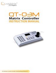
<strong>Quaddrix</strong> <strong>QT</strong>-<strong>500</strong> <strong>Series</strong> <strong>Stand</strong> <strong>Alone</strong> <strong>DVR</strong><br />
<strong>User</strong> <strong>Manual</strong><br />
(<strong>Rev</strong>. <strong>20</strong>/<strong>12</strong>/<strong>20</strong>06)<br />
This manual is applicable for <strong>QT</strong>-<strong>500</strong>-4, <strong>QT</strong>-<strong>500</strong>-8 and <strong>QT</strong>-<strong>500</strong>-16 embedded <strong>DVR</strong>s. Read this <strong>User</strong><br />
<strong>Manual</strong> carefully to ensure that you can use the device correctly and safely.<br />
The contents of this <strong>Manual</strong> are subject to change without notice.
Index<br />
Chapter 1 Product Introduction ............................................................................................... 4<br />
1.1 Summary ...............................................................................................................4<br />
1.2 Features .................................................................................................................4<br />
Chapter 2 Installation .................................................................................................................. 7<br />
2.1 HDD Installation..................................................................................................7<br />
2.3 Rear Panel Description .....................................................................................8<br />
2.4 External Alarm In/Out Connection...............................................................9<br />
Chapter 3 Operational Instructions .......................................................................................11<br />
3.1 Front Panel..........................................................................................................11<br />
3.2 IR Remote Controller ......................................................................................13<br />
3.3 Menu Description..............................................................................................16<br />
3.3.1 Menu Items.........................................................................................16<br />
3.3.2 Menu Operation.................................................................................17<br />
3.4 Character Input.................................................................................................<strong>20</strong><br />
Chapter 4 Basic Operation Guide .......................................................................................... 21<br />
4.1 Power on ..............................................................................................................21<br />
4.2 Preview.................................................................................................................22<br />
4.3 <strong>User</strong> name and password..............................................................................25<br />
4.4 PTZ Control.........................................................................................................27<br />
4.5 <strong>Manual</strong> Record ...................................................................................................30<br />
4.6 Playback...............................................................................................................31<br />
4.7 Backup Recorded Files....................................................................................36<br />
4.8 Shut Down <strong>DVR</strong>.................................................................................................39<br />
Chapter 5 Parameters Setup Guide...................................................................................... 41<br />
5.1 Administrator and Password.........................................................................41<br />
5.2 Add and Delete <strong>User</strong> .......................................................................................44<br />
5.3 Unit Name and Device ID..............................................................................49<br />
5.4 Video Output <strong>Stand</strong>ard and VGA Setup...................................................50<br />
5.5 OSD Setup...........................................................................................................51<br />
5.6 Video Parameters Setup ................................................................................55<br />
5.7 Mask Area Setup...............................................................................................56<br />
5.8 View Tampering Alarm....................................................................................59<br />
5.9 Video Loss Alarm ..............................................................................................61<br />
5.10 Motion Detection Alarm..................................................................................63<br />
5.11 Preview Properties ...........................................................................................68<br />
5.<strong>12</strong> Recording Setup................................................................................................70<br />
5.13 External Alarm Input and Relay Output ..................................................76<br />
5.14 Network Parameters........................................................................................81<br />
5.15 PTZ.........................................................................................................................83
5.16 RS232 setup.......................................................................................................88<br />
5.17 Exceptions ...........................................................................................................95<br />
5.18 Transaction Information.................................................................................96<br />
Chapter 6 Utilities...................................................................................................................... 102<br />
6.1 Save Parameters.............................................................................................102<br />
6.2 Restore Parameters .......................................................................................103<br />
6.3 Upgrade..............................................................................................................103<br />
6.4 Hard Disk Management................................................................................104<br />
6.5 Clear Alarm Out ..............................................................................................105<br />
6.6 Reboot.................................................................................................................105<br />
6.7 Power Off ...........................................................................................................105<br />
6.8 View Log.............................................................................................................105<br />
6.9 System Information.......................................................................................109<br />
Chapter 7 Firmware Upgrade.................................................................................................110<br />
7.1 FTP Server Setup............................................................................................110<br />
7.2 Upgrade Mode..................................................................................................114<br />
Appendix A...............................................................................................................................................116<br />
Appendix B...............................................................................................................................................116<br />
Appendix B...............................................................................................................................................117<br />
<strong>DVR</strong> Connect Cable Definition ..........................................................................................................117<br />
1 UTP network connect cable made method ...........................................117<br />
2 RS-232 connect cable made method......................................................119<br />
Appendix C.............................................................................................................................................. 1<strong>20</strong><br />
Specifications......................................................................................................................................... 1<strong>20</strong><br />
Appendix D ............................................................................................................................................. <strong>12</strong>2<br />
List of Recommended <strong>DVR</strong> Peripherals........................................................................................ <strong>12</strong>2<br />
Appendix E.............................................................................................................................................. <strong>12</strong>4<br />
Quick Search Function Table............................................................................................................ <strong>12</strong>4<br />
Appendix F .............................................................................................................................................. <strong>12</strong>6<br />
Troubleshooting..................................................................................................................................... <strong>12</strong>6
Chapter 1 Product Introduction<br />
1.1 Summary<br />
The <strong>QT</strong>-<strong>500</strong> series network digital video recorder is an excellent digital<br />
surveillance product. It uses the embedded MCU and real time operating<br />
system, combining the most advanced technology in Information Industry<br />
such as video and audio encoding/decoding, hard disk record and TCP/IP.<br />
The firmware is burned in a flash (not in a hard disk), making it more<br />
stable and reliable.<br />
<strong>QT</strong>-<strong>500</strong> series device has both the features of digital video recorder (<strong>DVR</strong>)<br />
and digital video server (DVS). It can work stand alone, also be used to<br />
build a powerful surveillance network, widely used in bank,<br />
telecommunication, transportation, factories, warehouse, irrigation, etc.<br />
1.2 Features<br />
Compression<br />
• Support max. 16 channels video input (PAL/NTSC) at most. Each<br />
channel is independent, H.264 hardware compression. For <strong>QT</strong>-<strong>500</strong>-<br />
4 and <strong>QT</strong>-<strong>500</strong>-8 the total frame is 1<strong>20</strong>FPS NTSC (100FPS PAL). For<br />
<strong>QT</strong>-<strong>500</strong>-16 the total frame 240FPS NTSC (first 8-ch 1<strong>20</strong>FPS and<br />
second 8-ch 1<strong>20</strong>FPS) or <strong>20</strong>0 FPS PAL (first 8-ch 100FPS and second<br />
8-ch 100FPS) or. Support both variable bitrate and variable frame<br />
rate.<br />
• Support 4 channels audio inputs. Each channel is independent,
OggVorbis compression and bitrate is 16Kbps. <strong>QT</strong>-<strong>500</strong>-8 doesn’t<br />
have audio inputs.<br />
• Compressed video and audio are synchronous. You can select<br />
either mixed stream or only video stream.<br />
• Support video loop.<br />
• Support CIF and QCIF resolution.<br />
• Support multi area motion detection.<br />
• Support OSD and changeable OSD position.<br />
Local functions<br />
Record<br />
• Support multiple record type, including real time, manual record,<br />
motion detection, external alarm, motion&alarm, motion|alarm.<br />
• Support max. 4 IDE HDDs and each HDD can max support <strong>20</strong>00GB.<br />
• Support FAT32 file system.<br />
• Support HDD S.M.A.R.T technology.<br />
• Support cycle or none cycle record.<br />
• Support backup the recorded files and clips. Support USB memory,<br />
USB HDD, USB CD-R/W, USB DVD-R/W, IDE CD-R/W and IDE<br />
DVD-R/W.<br />
Preview and playback<br />
• Support analog monitor and VGA output.<br />
• Support multiple preview modes.<br />
• Support sensitive area mask.<br />
• Support camera spiteful block alarm.<br />
• Support one channel play back by files or by time.<br />
• Display local record status.<br />
PTZ<br />
• Support many kinds of PTZ protocol.<br />
• Support preset, sequence and cruise.<br />
Alarms<br />
• Support exception alarm, motion detection alarm, external alarm,
etc.<br />
Others<br />
• Support IR Remote Control.<br />
• Support multi-level user management.<br />
Network<br />
• Support TCP, UDP, RTP, Multicast for network preview.<br />
• Support PPPoE for board band dialup.<br />
• Support PSTN for narrow band dialup.<br />
• Support remote parameters setup.<br />
• Alarm information can be sent to remote center.<br />
• Network control PTZ.<br />
• Network record live stream.<br />
• Network download and playback the recorded files in <strong>DVR</strong>.<br />
• Remote upgrade the firmware.<br />
• RS-232 supports transparent channel function so that the remote<br />
PC can use <strong>DVR</strong> to control serial devices.<br />
• Support IE to preview and config <strong>DVR</strong>.<br />
• Support log.
Chapter 2 Installation<br />
Warning: Before you install the Hard Disks, please make sure the<br />
power of <strong>DVR</strong> is switched off.<br />
2.1 HDD Installation<br />
Installation notice<br />
The <strong>DVR</strong> by factory default has not HDD installed. Based on the record<br />
schedule, you can calculate the total capacity you need (refer to Appendix<br />
A).<br />
HDD installation<br />
1. Open the <strong>DVR</strong> box.<br />
2. If you want to install 2 HDD for one IDE interface, please set master<br />
and slave HDD (set the jumpers properly in the HD). If you want to<br />
install 4 HDD, please remove CD-R/W mount bracket.<br />
3. Place the HDD on the soleplate and fix it with screw.<br />
4. Connect the ATA data cable correctly. The cable has three<br />
connectors for <strong>DVR</strong> main board, master HDD and slaver HDD.<br />
5. Plug the HDD power connector.<br />
6. Cover and fix the <strong>DVR</strong> box.<br />
Note: After you install the HDD, you must format them. Please refer to<br />
section 6.4.
2.3 Rear Panel Description<br />
Notice: Please refer to real product for different model.<br />
<br />
<br />
<br />
<strong>QT</strong>-<strong>500</strong>-16 Rear Panel<br />
<br />
<br />
<strong>QT</strong>-<strong>500</strong>-4 Rear Panel<br />
Index Physical Interface Description<br />
1 Video Input <strong>Stand</strong>ard BNC.<br />
2<br />
Video Output<br />
Connect monitor, output video and<br />
menu.<br />
Audio Output 1 channel RCA (1.0 Vp-p, 75Ω)<br />
3 Audio input 4 channel RCA (1.0 Vp-p, 75Ω)<br />
4 Video Loop out<br />
<strong>QT</strong>-<strong>500</strong>-16 uses DB15 connectors. <strong>QT</strong>-<br />
<strong>500</strong>-4 uses on board BNC connectors.<br />
5 VGA Interface VGA display.
6<br />
7<br />
RS-232<br />
UTP Network<br />
Interface<br />
RS-485<br />
External Alarm<br />
Input<br />
Relay Output<br />
Connect RS-232 devices. Refer to<br />
Appendix B for pin definition.<br />
Connect network devices. Refer to<br />
Appendix B for pin definition.<br />
PTZ connection. Refer to Appendix B for<br />
pin definition.<br />
4/8/16 Alarm in.<br />
2/4 Alarm out<br />
8 AC Input 100V~240VAC<br />
2.4 External Alarm In/Out Connection<br />
Alarm input port:<br />
G (GND): Connect the GND of sensor.<br />
1~16: Alarm input, support normal open/normal close.<br />
0: Reserved.<br />
Alarm output:<br />
1G~4G: 4 relay output.<br />
Alarm output connection<br />
Please note the usage of jumper JJ1. If you use DC, either of connections<br />
is OK. We suggest you to use those DC under <strong>12</strong>V, 1A.
If you use AC, please open the jumper. There are 4 jumpers (JJ1, JJ2, JJ3<br />
and JJ4) in <strong>DVR</strong> main board, corresponding with 4 alarm output. The<br />
default is closed.<br />
Warning: If you use AC input for relay output, please open the<br />
jumpers.
Chapter 3 Operational Instructions<br />
3.1 Front Panel<br />
<br />
<br />
<br />
Index Type Name Description<br />
1 State<br />
Lamps<br />
READY<br />
STATUS<br />
ALARM<br />
RECORD<br />
NETWORK<br />
<strong>DVR</strong> is ready.<br />
Green means you can use IR remote<br />
control.<br />
Red means there is alarm.<br />
Twinkle in red means reading or<br />
writing HDD.<br />
Network status.<br />
2 Lamp IR receiver.<br />
Numeric<br />
Keys<br />
Input number, lower case, upper case<br />
character and symbols.<br />
MENU 1. Switch preview mode into menu;<br />
3 Function<br />
2. Brush control short key [WIPER] .<br />
3. Press [MENU] for more than 5<br />
seconds to cancel button beep<br />
sound.<br />
Keys 2<br />
3<br />
ESC<br />
[ZOOM-] in PTZ control.<br />
[ZOOM+] in PTZ control.<br />
Cancel and back to parent menu.
4 Control<br />
Keys<br />
EDIT<br />
PLAY<br />
REC<br />
PTZ<br />
PREV<br />
A<br />
SHIFT<br />
Direction<br />
Keys<br />
ENTER<br />
1. In edit state, delete the current<br />
cursor character;<br />
2. [IRIS+] in PTZ control;<br />
3. Select or × to enable or disable.<br />
1. Local playback;<br />
2. [AUTO] in PTZ control.<br />
1. <strong>Manual</strong> record;<br />
2. [SHOT] in PTZ control (adjust<br />
preset).<br />
1. Enter into PTZ control mode;<br />
2. [IRIS-] in PTZ control..<br />
1. Multi screen preview switch;<br />
2. Switch menu mode into preview;<br />
[FOCUS-] in PTZ control.<br />
1. Input switch (number, lower<br />
case, upper case and symbol);<br />
2. [FOCUS+] in PTZ control;<br />
3. In preview mode, display or hide<br />
the channel status bar.<br />
Switch between numeric keys and<br />
function keys<br />
Composed of [] , [] , [] and<br />
[] .<br />
1. Menu mode, use [] / [] select,<br />
[] / [] to edit;<br />
2. PTZ direction control;<br />
3. Playback speed control.<br />
1. Menu confirmation;<br />
2. Select or × to enable or disable;<br />
3. Pause playback.<br />
5 POWER POWER Device switch with power indicator<br />
lamp. Green means <strong>DVR</strong> is working;<br />
Red means <strong>DVR</strong> is powered off; No<br />
light means no power is supplied.<br />
Please note that [SHIFT] button is used to switch between<br />
numeric keys and function keys.
3.2 IR Remote Controller<br />
Inde<br />
x<br />
Name<br />
Description<br />
1 POWER Turnoff device.<br />
2 DEV<br />
3 Numeric Keys<br />
4 EDIT<br />
5 A<br />
Enable/Disable IR remote<br />
control<br />
Same as numeric keys of<br />
front panel.<br />
Same as EDIT key of<br />
front panel.<br />
Same as A key of front<br />
panel.
6 REC<br />
7 PLAY<br />
8 INFO<br />
9 VOIP<br />
10 MENU<br />
11 PREV<br />
<strong>12</strong><br />
13 PTZ<br />
14 ESC<br />
Direction Keys<br />
ENTER<br />
15 Reserved<br />
16 F1<br />
17 Lens control<br />
18 F2<br />
Same as REC key of front<br />
panel.<br />
Same as PLAY key of<br />
front panel.<br />
Same as INFO key of<br />
front panel.<br />
Same as VOIP key of<br />
front panel.<br />
Same as MENU key of<br />
front panel.<br />
Same as PREV key of<br />
front panel.<br />
Same as direction keys<br />
and enter key of front<br />
panel.<br />
Same PTZ key of front<br />
panel.<br />
Same as ESC key of front<br />
panel.<br />
Same as [F1] key of front<br />
panel.<br />
IRIS, FOCUS ZOOM for<br />
lens control.<br />
Same as [F2] key of front<br />
panel.<br />
Loading the batteries into the IR Remote Controller<br />
1. Remove the battery cover.<br />
2. Insert the battery. Please take care that the poles (+ and -) are<br />
correctly positioned.<br />
3. Replace the battery cover.<br />
Start to use IR Remote Controller<br />
Press [DEV] key, input the <strong>DVR</strong> device ID (default is “88”, can be changed
in “Display” menu) and then press [ENTER] key. If the “STATUS” lamp of<br />
<strong>DVR</strong> front panel is turned into green, it means you can use IR Remote<br />
Controller to operate this <strong>DVR</strong>.<br />
Stop using IR Remote Controller<br />
When IR Remote Controller status is on, press [DEV] key again, the<br />
“STATUS” lamp will be turned off. The IR Remote Controller can not<br />
control this <strong>DVR</strong>.<br />
Switch the <strong>DVR</strong> off<br />
When IR Remote Controller status is on, press [POWER] key for several<br />
seconds, the <strong>DVR</strong> will be powered off.<br />
If the IR Remote Controller doesn’t work properly<br />
• Check batteries poles.<br />
• Check the remaining charge in the batteries.<br />
• Check IR Remote Controller sensor is mask.<br />
Please change another IR Remote Controller to try again. It the problem is<br />
still existed, please contact your distributor.
3.3 Menu Description<br />
3.3.1 Menu Items<br />
Menu Name Function Menu Name Function<br />
Display<br />
Recording<br />
Alarms<br />
Unit name<br />
Device ID<br />
Require password<br />
Screen saver<br />
Video standard<br />
Brightness<br />
Menu transparency<br />
VGA resolution<br />
DST<br />
Date and Time<br />
Overwrite/Stop<br />
recording<br />
Resolution and<br />
recording<br />
parameters setup<br />
Record schedule<br />
PreRecord time<br />
PostRecord time<br />
Alarm input type<br />
(Normal open/<br />
Normal close)<br />
Alarm response and<br />
Image<br />
Network<br />
Camera name and<br />
position setup<br />
Adjust Brightness,<br />
Contrast, Hue and<br />
Saturation<br />
OSD Display mode,<br />
position and OSD<br />
format setup<br />
Mask area setup<br />
View tampering area<br />
and response setup<br />
Video signal loss<br />
Motion detection<br />
sensitivity, area and<br />
response setup<br />
<strong>DVR</strong> IP address<br />
DNS IP<br />
Multicast IP address<br />
Remote host IP and<br />
port<br />
NAS IP and directory<br />
PPPoE username and<br />
password<br />
Exceptions Exceptions type<br />
Exceptions response
PTZ<br />
Preview<br />
PTZ linkage<br />
Alarm output and<br />
schedule<br />
PTZ parameters<br />
Preset setup<br />
Sequence setup<br />
Cruise setup<br />
Preview mode<br />
Switch time<br />
Enable/Disable audio<br />
preview<br />
Preview layout<br />
RS232<br />
<strong>User</strong><br />
Password<br />
RS232 parameters<br />
RS232 work mode<br />
Add or delete user<br />
Password setup or<br />
modification<br />
<strong>User</strong> rights setup<br />
Transaction<br />
Text input mode<br />
ATM IP address<br />
ATM type<br />
Text information<br />
Utilities<br />
Restore parameters<br />
Upgrade firmware<br />
HDD management<br />
Clear alarm output<br />
Reboot<br />
Power off<br />
View log<br />
System information<br />
3.3.2 Menu Operation<br />
How to enter into menu mode<br />
• Press [MENU] key to enter into <strong>DVR</strong> main menu.<br />
• Press [PLAY] short key to enter into playback menu.<br />
• Press [REC] short key to enter into manual record menu.<br />
• Press [PTZ] short key to enter into PTZ control interface.<br />
Notes: You must input user name and password. The default user<br />
name is “admin” and password is “<strong>12</strong>345”.
Main Menu Description<br />
The main menu interface is following:<br />
There is one small rectangular frame named “Active Frame”. It can be<br />
moved from one icon to another by using [] or [] key. When the<br />
“Active Frame” is located on one icon, you can press [ENTER] key to enter<br />
into the secondary menu. For example, move the “Active Frame” to<br />
“Image” icon, press [ENTER] to enter into the secondary menu as<br />
following:
Each menu contains different kinds of items. There is a small rectangular<br />
frame named “Active Frame” which is pointing to the selected item. This<br />
“Active Frame” can be moved by [] or [] keys. There are such kinds of<br />
menu items:<br />
1. Check Box: Provide 2 options, “” means enable and “×” means<br />
disable. You can use [ENTER] or [EDIT] key to switch over.<br />
2. List Box: Provide more than 2 options. However, only one of them<br />
can be selected. You can use [] and [] to select one option. For<br />
example, on the right side of “Select Camera”, there is a list box<br />
for you to select one camera.<br />
3. Edit Box: This is for you to input characters. Press [EDIT] key to<br />
enter into edit status, you can input characters as following:<br />
a) Press [A] key to select number, upper case, lower case or<br />
symbols;<br />
b) Use [] and [] keys to move cursor;<br />
c) Use [EDIT] key to delete the character in front of cursor;<br />
d) Press [ENTER] or [ESC] to exit edit.<br />
4. Button: Execute a special function or enter into next sub-menu.<br />
For example, press “Policy” button to enter into sub-menu. Press<br />
[Confirm] to save parameters and return to parent menu. Press<br />
[Cancel] button to cancel and return to parent menu. The button in
grey means it can be operated only after it is enabled.<br />
How to exit menu<br />
Press [PREV] key to exit menu and return to preview mode.<br />
3.4 Character Input<br />
In the menu interface, if you enter into edit status (for example, in the<br />
“camera name” edit box), at the bottom of screen, the input status is<br />
appeared:<br />
Here it means you can press numeric keys to input digital number.<br />
Press [A] key to change input methods. You can select “number”,<br />
“Uppercase”, “Lowercase” or “Symbol”.<br />
Uppercase<br />
Lowercase<br />
Symbol<br />
There are 24 symbols in all. They are divided into 4 pages, and you can<br />
use [0] key to turn over page.
Chapter 4 Basic Operation Guide<br />
4.1 Power on<br />
Note: Please make sure the power supply matches <strong>DVR</strong> and AC<br />
cable connected correctly. Before switch <strong>DVR</strong> on, please connect<br />
one monitor with VOUT or VGA interface. Otherwise, you can not<br />
see graphic user interface and can not operate.<br />
If [POWER] lamp is off, please do as following:<br />
Step1: Connect AC cable correctly;<br />
Step2: Switch on the power button on the real panel.<br />
If [POWER] lamp is in red, just press [POWER] button to start <strong>DVR</strong>.<br />
When <strong>DVR</strong> is started, [POWER] lamp is in green. On the monitor or VGA<br />
display, DSP and HDD initialization process will be shown.<br />
The first line represents DSP initialization. If the DSP icon is “×”, it means<br />
that the DSP is initialized error, please contact administrator at once.<br />
The second line represents HDD initialization. Icons of IDE1 master and<br />
slaver HDDs, IDE2 master and slaver HDDs, etc are displayed. If the HDD<br />
icon is “×”, it means the corresponding HDD is not installed or not<br />
detected. If HDD is not detected, please contact administrator.<br />
Note: If HDD is not installed or not detected, <strong>DVR</strong> will beep for<br />
alarm. You can disable the alarm option in “Exceptions” menu.
4.2 Preview<br />
<strong>DVR</strong> will enter into preview mode after it is started.<br />
On preview screen, you can see date, time, camera name and camera<br />
status icon.<br />
Set system date and time in “Display” menu, referring to 5.2.9; Change<br />
camera name in “Image” menu, referring to 5.3.2.<br />
In the screen, it will display record and alarm status of each camera.<br />
These two kinds of status will switch over automatically.<br />
Press [A] key to display or hide the camera status bar.<br />
Camera record status is following:
Icon<br />
Icon<br />
Color<br />
White<br />
Yellow<br />
Pink<br />
Green<br />
Blue<br />
Red<br />
Status Description<br />
No video signal<br />
Video input<br />
<strong>Manual</strong> recording<br />
Real time recording<br />
Motion detect recording<br />
External alarm recording<br />
Camera alarm status is following:
Icon Icon Color Status Description<br />
White<br />
Yellow<br />
Pink<br />
Green<br />
Blue<br />
Red<br />
Video signal lost<br />
View tampering alarm<br />
Motion&External alarm<br />
No alarm<br />
Motion alarm<br />
External alarm<br />
Press numeric keys to switch over individual camera preview. If <strong>DVR</strong> has<br />
less than 10 channels, press one numeric key to switch corresponding<br />
channel. For example, press [2] key to preview 2 nd camera. If <strong>DVR</strong> has<br />
10 or more than 10 channels, press two numeric keys to switch<br />
corresponding channel. For example, press [0] [2] to preview 2 nd<br />
camera; and press [1] [2] keys to preview <strong>12</strong> th camera.<br />
Press [EDIT] key to manual cycle preview. You can set the auto preview<br />
mode in “Preview” menu, referring to 5.11.<br />
Press [PREV] key to switch multi-screen preview.
4.3 <strong>User</strong> name and password<br />
Note: When <strong>DVR</strong> is delivered from factory, there is only one<br />
default administrator named “admin”, and password is “<strong>12</strong>345”.<br />
The administrator’s name can not be modified, while the password<br />
can be modified. The administrator can create 15 users and define<br />
their user rights.<br />
Login<br />
Login dialog is following:<br />
Use [] / [] keys to select one user, press [] key to enter into<br />
“Password” edit box, input corresponding password, press [ENTER] key to<br />
exit edit box. The “Active Frame” will be moved to “Confirm” button. Press<br />
[ENTER] key to enter into main menu. If there is beeper alarm, it means<br />
the user name and password are not matched. After three error times,<br />
<strong>DVR</strong> will enter into preview mode.<br />
Modify password<br />
For those users created by admin, they can modify their password as<br />
following:<br />
Step1: Enter into main menu<br />
Press [MENU] key, in the login dialog, select your user name, input the<br />
correct password, you can enter into the main menu.
Step 2: Enter into password modification menu<br />
Move the “Active Frame” to “Password” icon by using [] / [] keys.<br />
Press [ENTER] key to enter into following password menu:
Step 3: Input new password<br />
Press [EDIT] key to enter into edit box. You can use numeric keys to input<br />
new password. The password can be null. It also can be 16 numerals.<br />
Press [ENTER] to exit edit box, and move to “Verify” item to input the<br />
verify password.<br />
Note: In edit box, use [] / [] to move cursor and [EDIT] key to<br />
delete the numeral in front of the cursor.<br />
Step 4: Modify password successfully<br />
Move the “Active Frame” to “Confirm” button, press [ENTER] key. If the<br />
password is modified successfully, you will get the main menu. Or an error<br />
dialog will be pop up. You can repeat step 3 to modify again.<br />
4.4 PTZ Control<br />
Note: The user must have the “PTZ control” right.<br />
PTZ control interface<br />
In preview mode, press [PTZ] key, in the login dialog, select one user<br />
name and input the correct password, you can enter into PTZ control<br />
interface.<br />
In menu mode, press [PTZ] key, you can enter into PTZ control interface<br />
directly.
There is “PTZ Control” prompt in the PTZ control interface. The displayed<br />
camera name means which channel’s PTZ is under control. For example,<br />
“Camera 01” means you are controlling the 1 st camera PTZ.<br />
Select channel<br />
In PTZ control mode, you can press numeric keys to select channel. If<br />
<strong>DVR</strong> has less than 10 channels, press one numeric key to select. For<br />
example, press [2] key to select 2 nd camera PTZ. If <strong>DVR</strong> has 10 or more<br />
than 10 channels, you must press two numeric keys to select. For<br />
example, press [0] [2] to select 2 nd camera PTZ, and press [1] [2]<br />
to select <strong>12</strong> th camera PTZ.<br />
After you select the camera PTZ, you can use the short keys to control<br />
PTZ.<br />
PTZ control keys description<br />
Direction control keys: [] , [] , [] , [] ;<br />
ZOOM control keys: [ZOOM+] , [ZOOM-] ;<br />
FOCUS control keys: [FOCUS+] , [FOCUS-] ;<br />
IRIS control keys: [IRIS+] , [IRIS-] ;<br />
Adjust preset keys: [REC/SHOT] ;
Auto control key: [PLAY/AUTO] ;<br />
Wiper control key: [WIPER/MENU] ;<br />
Light control key: [LIGHT/F1] ;<br />
Auxiliary device control key: [AUX/F2]<br />
Preset Setting<br />
In PTZ control mode, press [REC/SHOT] key, and press the preset number<br />
(three numeric keys), <strong>DVR</strong> will adjust the corresponding preset number.<br />
Repeat pressing [REC/SHOT] key, and press the preset number, <strong>DVR</strong> will<br />
adjust that preset number.<br />
When you exit PTZ control mode, the camera will stay at the current<br />
position.<br />
Note: The PTZ preset number is set already. Please refer to PTZ menu for<br />
preset setup. V1.4 firmware can support <strong>12</strong>8 preset numbers at most.<br />
Start/Stop auto in PTZ control mode<br />
In PTZ control mode, press [PLAY/AUTO] key to start PTZ auto function.<br />
Press [PLAY/AUTO] key again to stop.<br />
When PTZ is in auto mode, if you exit PTZ control mode, PTZ will continue<br />
auto function. You must enter into PTZ control mode again, and press<br />
[PLAY/AUTO] key to stop.<br />
Exit PTZ control mode<br />
Press [ESC] or [ENTER] to exit and return preview mode.
4.5 <strong>Manual</strong> Record<br />
Note: The user must have the corresponding right, <strong>DVR</strong> has HDD<br />
and HDD is formatted already.<br />
<strong>Manual</strong> record<br />
In preview mode, press [REC] key, in the pop-up login dialog, select the<br />
name and input the correct password, you can enter into the “<strong>Manual</strong><br />
Record” interface.<br />
In menu mode, press [REC] key to enter into “<strong>Manual</strong> Record” interface<br />
directly.<br />
Description<br />
<strong>Manual</strong> record interface has following parts: channel number, channel<br />
status, start/stop record, start all and stop all buttons.<br />
Channel: List the channel number that <strong>DVR</strong> has.<br />
Status: Channel work status has 4 cases: means idle. Green means the<br />
channel is recording (including real time recording, alarm recording,
motion detection recording). Red means network transmission. Orange<br />
means both recording and network transmission.<br />
Start/Stop: “” means you can start corresponding channel recording.<br />
“×” means you can stop recording.<br />
Start All: Press this button to start all channels recording.<br />
Stop All: Press this button to stop all channel recording.<br />
Exit manual record<br />
Press [ESC] key to enter into preview mode. Press [MENU] key to enter<br />
into main menu. Press [PLAY] key to enter into playback menu. Press<br />
[PTZ] key to enter into PTZ control mode.<br />
4.6 Playback<br />
Note: The user must have “Playback” right.<br />
Playback interface<br />
In preview mode, press [PLAY] key, in the pop-up login dialog, select<br />
username and input correct password, you can enter into “Playback”<br />
interface.<br />
In menu mode, press [PLAY] key, you can enter into “Playback” interface<br />
directly.
Playback<br />
Description<br />
This series <strong>DVR</strong> only supports one channel playback,<br />
Chan: Use [] or [] key to select one channel.<br />
Rec Type: Use [] or [] to select recorded files type. The file type<br />
options have “All”, “All Time”, “Motion Detect”, “Alarm” and “<strong>Manual</strong>”.<br />
Time Section: You can define the search time section. Move “Active<br />
Frame” to the time edit box, use numeric keys to input the detail time.<br />
Card Number: <strong>DVR</strong> can get text number through RS-232 or network<br />
port. The text is sent from devices such as ATM machine, POS machine or<br />
others. <strong>DVR</strong> can overlay the text on the real time image and record. You<br />
can use the text to search the recorded files and playback them. Use the<br />
numeric keys to input the text number.
Search: Search the matched recorded files and display them in the list<br />
box. If there is not matched file, a corresponding dialog box will be popup.<br />
Play by Time: Playback the recorded stream directly based on the time<br />
section.<br />
Select Page: In the file list box, each page will only display 8 files. If the<br />
matched files are more than 8, you can select page to list other files. <strong>500</strong><br />
pages (4000 files) can be searched in one time. You can use numeric keys<br />
or [] or [] keys to select page.<br />
File List Box: List the matched files. File started time, file size are<br />
displayed in the list box. You can use [] or [] keys to move the scroll<br />
bar to select file.<br />
Backup Devices: You can select USB flash, USB HDD, USB CD-R/W or<br />
IDE CD-R/W to backup the files or clips.<br />
Copy: Start to backup.<br />
Backup Today: Backup all recorded files of today.<br />
Three kinds of playback mode<br />
1. Search and playback file: In the playback interface, you can select<br />
main channel, second channel (2-ch playback), record type, time section.<br />
Move “Active Frame” to “Search” button and press [ENTER] key, <strong>DVR</strong> will<br />
search and list the matched files.
If the matched files are more than 8, you can use “Page No.” to select<br />
page (use numeric keys or [] [] keys to select page). In the file list<br />
box, use [] or [] keys to move the scroll bar to the file, press [ENTER]<br />
key to playback the file. If the second channel is selected, these two<br />
channels can be playback synchronously.<br />
If <strong>DVR</strong> can not find the matched files, a failure dialog box will be pop-up.<br />
2. Playback by Time: In the playback interface, select channel number,<br />
record type and time section, move “Active Frame” to “Play” button, press<br />
[ENTER] key, <strong>DVR</strong> will start to playback based on time section.<br />
3. Search by Card No and Playback file: In the playback interface,<br />
select channel number, record type, enable card No. search option (“”)<br />
and input the card number, move “Active Frame” to “Search” button,<br />
press [ENTER] key, <strong>DVR</strong> will search and list the matched files. If the<br />
matched files are more than 8, you can use numeric keys or [] [] keys<br />
to select page. Use [] [] keys to move scroll bar to the file, press<br />
[ENTER] key to playback the selected file. If <strong>DVR</strong> can not find the matched<br />
files, a message dialog will be pop-up.
Operation when playback<br />
Playback picture:<br />
Playback<br />
At the bottom of image, there is an information bar and the following<br />
information is included: Volume, Play Progress, Play Speed, Played Time<br />
and File Total Time.<br />
• Display/Hide information bar: [MENU]<br />
• Open/Close sound: [PLAY]<br />
• Adjust play progress: [] (Backward), [] (Forward). The unit<br />
is “%”.<br />
• Adjust play speed: Normal speed is “1x”. Use [] to increase<br />
play speed (2X, 4X, 8X and MAX). Use [] to decrease play<br />
speed (1/2X, 1/4X, 1/8X and Frame by Frame)<br />
• Pause/Continue: Press [ENTER] to pause/continue playback. If<br />
played frame by frame, Press [ENTER] to play one frame.<br />
• Copy segment: [EDIT]<br />
• Exit: [ESC]<br />
Note: When <strong>DVR</strong> is busy, if you select high play speed, maybe there is
difference for actual play speed.<br />
Exit playback<br />
In playback interface, press [ESC] key to enter into preview mode.<br />
In playback interface, press [MENU] key to enter into main menu, press<br />
[REC] key to enter into manual record, and press [PTZ] key to enter into<br />
PTZ control mode.<br />
4.7 Backup Recorded Files<br />
Note: The user must have “Playback” right. Please connect with<br />
backup devices before you start to backup.<br />
In the playback interface, you can backup the recorded files.<br />
In the preview mode, press [PLAY] key, in the login dialog, select<br />
username and input the correct password, you can enter into the playback<br />
interface.<br />
In the menu mode, just press [PLAY] key, you can enter into playback<br />
interface directly.<br />
Backup intraday recorded files<br />
In the playback interface, move “Active Frame” to “Backup Today”<br />
button, press [ENTER] key, all intraday recorded files of all channels will<br />
be backup to the save device. A pop-up dialog will display the backup<br />
status.<br />
If backup device is not connected correctly or <strong>DVR</strong> do not detect the<br />
backup device, the following dialog will be pop-up. Please ask<br />
administrator for more information.
Backup the files that matched your requirement<br />
Step 1: Search the matched files<br />
In the playback interface, select one channel and record type, input the<br />
time section, move “Active Frame” to “Search” button, press [ENTER] key,<br />
<strong>DVR</strong> will start to find and list the matched files.<br />
Step 2: Select the files that you want to backup<br />
In the file list box, use [] or [] keys to move the scroll bar. When the<br />
scroll bar stays at the file you wan to backup, press [EDIT] key to select<br />
it. The symbol “” is the selection tag. You can use the same method to<br />
select other files you want to backup. After finish, you can do next step.
Step 3: Select backup device<br />
Please confirm the backup device: USB flash memory, USB HDD, USB CD-<br />
R/W or IDE CD-R/W, and select the corresponding backup device.<br />
Step 4: Start and finish backup<br />
Move “Active Frame” to “Copy” button and press [ENTER] key to start<br />
backup.<br />
When backup is started, corresponding message box will pop-up to<br />
indicate the result.<br />
Backup video segment<br />
You also can backup the image segments when the image is being<br />
playback. The steps are:<br />
1) Enter into the interface of playback the files or playback by time;<br />
2) Press [EDIT] key to start selecting the current playback image, and<br />
press [EDIT] again to stop selecting. This segment is selected;<br />
3) You can repeat step 2 to select many segments. 30 segments can<br />
be selected in all;<br />
4) After you select all segments, press [ESC] key, a message window<br />
will pop-up. If you press “Confirm” button, <strong>DVR</strong> will start to backup<br />
the selected segments. If you press “Cancel” button, <strong>DVR</strong> will abort<br />
backup.<br />
Note: The backup function is effective when two channels are playback<br />
synchronously. In such case, each channel can backup 30 segments so 60<br />
segments can be backup for two channels.<br />
Playback the video segment<br />
You can use our file player software to playback the video segment in PC.<br />
You can find the player software in attached CD. (In the installation folder<br />
C:\Program Files\<strong>Quaddrix</strong> Net<strong>DVR</strong>\Player.exe)<br />
Exit playback interface<br />
Please refer to chapter 4.6.
4.8 Shut Down <strong>DVR</strong><br />
Note: Do not switch off the power directly in case of damaging<br />
HDD. The correct step is using “Power Off” in the “Utilities” menu,<br />
or [POWER] key on the front panel or on IR Remote Controller.<br />
Shut down <strong>DVR</strong> normally<br />
Use menu<br />
Enter into “Utilities” menu, move “Active Frame” to “Power Off” button<br />
and enter into power off dialog, press “Confirm” to shut down the <strong>DVR</strong>.<br />
Use [POWER] key of front panel or IR Remote Controller<br />
Press [POWER] key for above 3 seconds.<br />
In preview mode, a login dialog will pop-up, select user name and input<br />
password, press [Enter] to enter into power off dialog and press “Confirm”<br />
to shut down <strong>DVR</strong>. If you input error password for three times, <strong>DVR</strong> will<br />
return preview mode.<br />
In menu mode, if the user has “Utilities” right, you can enter into power<br />
off dialog, press “Confirm” to shut down <strong>DVR</strong>. Otherwise, the user can not<br />
shut down <strong>DVR</strong>.<br />
If <strong>DVR</strong> is shut down correctly, the [POWER] lamp is in red.<br />
Note: When message of “Shut down…” is appeared, please do not press<br />
[POWER] key any more, otherwise, <strong>DVR</strong> can not be shut down.
Shut down <strong>DVR</strong> abnormally<br />
Use the power switch of real panel<br />
When <strong>DVR</strong> is run, if you switch off the power, the HDD in <strong>DVR</strong> will be<br />
damaged. Please avoid such operation.<br />
Take away the power cable<br />
Please avoid taking away the power cable directly.
Chapter 5 Parameters Setup Guide<br />
Only the users that have “Parameters Setup” right need read this chapter.<br />
When the following parameters are modified and saved, you must reboot<br />
the <strong>DVR</strong> to make the new parameters take into effective. Other<br />
parameters do not need to reboot.<br />
• Any network parameters<br />
• Stream type, resolution and record schedule<br />
• External alarm sensor type<br />
• View tampering alarm schedule<br />
• Video lost alarm schedule<br />
• Motion detection alarm schedule<br />
• External alarm schedule<br />
• Alarm output schedule<br />
• Transaction<br />
• RS232 work mode<br />
• Change video output standard<br />
5.1 Administrator and Password<br />
When <strong>DVR</strong> is left from factory, there is one default administrator. The<br />
name is “admin” and password is “<strong>12</strong>345”. The name can not be changed,<br />
while the password can be.<br />
Password modification<br />
Press [MENU] key, in the login dialog, select the username as “admin”,<br />
use [] key, move cursor to password edit box, input “<strong>12</strong>345”, press<br />
“Confirm” to enter into administrator menu.
Move “Active Frame” to “<strong>User</strong>” icon, press [ENTER] key to enter into “<strong>User</strong><br />
Management” menu.<br />
In the user name list box, only “admin” is existed. You can use [] key,<br />
move “Active Frame” to password edit box, and press [EDIT] key to enter<br />
into edit status. Press numeric keys to input the new password. The<br />
password is only combined by 16 numerals at most. After you finish<br />
inputting password, press [ENTER] key to exit. Move “Active Frame” to
“Verify password” edit box, input the verify password. Move “Active<br />
Frame” to “Confirm” button, and press [ENTER], if password and verify<br />
password are the same, the password will be saved and taken into<br />
effective.<br />
If password and verify password are not same, a warning message box<br />
will be appeared.<br />
In this case, press [ENTER] to return password edit box, and input new<br />
password again.
5.2 Add and Delete <strong>User</strong><br />
Enter into “<strong>User</strong> Management” interface.<br />
Add user<br />
The steps are following:<br />
Step 1: Enter into “<strong>User</strong> Management” menu<br />
Please refer to chapter 5.1<br />
Step 2: Add new user name<br />
In the “<strong>User</strong> Management” menu, move “Active Frame” to “Add”<br />
button and press [ENTER] , in the pop-up dialog, input the new user<br />
name (refer to chapter 3.4), press [ENTER] and return “<strong>User</strong><br />
Management” menu. 15 users can be added in all.
Step 3: Setup the password for new user<br />
After you add one new user, the password is null. You can skip this<br />
step if you do not want to change the password.<br />
In the users list box of “<strong>User</strong> Management” menu, use [] [] keys<br />
to select the new user name, then use [] key to the password edit<br />
box. Press [EDIT] key to enter into edit box, use numeric keys to input<br />
the new password.<br />
Step 3: Setup the rights for new user<br />
The new added user has not any operational rights. You must setup<br />
rights for him.<br />
In the users list box of “<strong>User</strong> Management” menu, use [] [] keys<br />
to select the new user name, then use [] key to “Default Rights”<br />
button, press [ENTER] , the user will have the default rights. The<br />
default rights include local playback, remote playback and view log.<br />
If you want to define the detail rights, move “Active Frame” to “Setup<br />
Rights” button and press [ENTER] to enter into rights setup menu as<br />
following:
Operational rights are divided into “Local Rights” and “Remote Rights”.<br />
You can assign the necessary rights to the user. Use [] [] key to<br />
move “Active Frame” to the corresponding right items, press [ENTER] or<br />
[EDIT] key to enable or disable the item. “” means assigning the right to<br />
that user.<br />
After you finish, press “Enter” button, the user’s rights will be saved and<br />
return “<strong>User</strong> Management” menu. If you press “Cancel” button, the user’s<br />
rights will be aborted.<br />
Step 4: Save the new user’s password and rights<br />
In the “<strong>User</strong> Management” menu, press “Confirm” button, the user’s<br />
password and rights will be saved and return main menu. If you press<br />
“Cancel” button, the user’s password and rights will be aborted.<br />
<strong>User</strong> rights description<br />
“Local Rights”:<br />
Local rights are for local operation, such as the operation using front<br />
panel, IR Remote Controller and RS-485 keyboard.<br />
- PTZ control: Locally control PTZ;<br />
- Record: <strong>Manual</strong> start/stop recording;
- Playback: Local playback and backup the recorded files;<br />
- Parameters Setup: Locally setup the <strong>DVR</strong> parameters;<br />
- Log: Locally view the log on <strong>DVR</strong>;<br />
- Utilities: Locally upgrade firmware, format HDD, reboot <strong>DVR</strong> and shut<br />
down <strong>DVR</strong>, etc.<br />
“Remote Rights”:<br />
- PTZ Control: Remote control PTZ;<br />
- Record: Remote manual start/stop recording;<br />
- Playback: Remote playback, download the recorded files on <strong>DVR</strong>;<br />
- Parameters Setup: Remote setup the <strong>DVR</strong> parameters;<br />
- Log: Remote view the log on <strong>DVR</strong>;<br />
- Utilities: Remote upgrade firmware, format HDD, reboot <strong>DVR</strong> and<br />
shut down <strong>DVR</strong>, etc.<br />
- Voice: Client talks with <strong>DVR</strong>;<br />
- Preview: Network live preview;<br />
- Alarm: Remote control <strong>DVR</strong> alarm output;<br />
- Local Video Out: Remote control <strong>DVR</strong> video output;<br />
- Com Control: <strong>DVR</strong> RS-232 transparent channel function.<br />
MAC address<br />
This MAC address is not the address of <strong>DVR</strong> but the PC that will access<br />
<strong>DVR</strong>. If you setup this MAC address, only the PC with this MAC address<br />
can access this <strong>DVR</strong>.<br />
At PC end, in DOS prompt, you can use “ipconfig” command to get the PC<br />
MAC address (6 bytes).<br />
Local Play<br />
Administrator Can setting local playback right option for each channel for<br />
users.<br />
Remote Play<br />
Administrator Can setting remote playback right option for each channel<br />
for users.
Remote Watch<br />
Administrator Can setting remote preview right option for each channel for<br />
users.<br />
Delete user<br />
In “<strong>User</strong> Management” interface, you can use [] [] keys to select one<br />
user, then use [] , move “Active Frame” to “Del” button, press [ENTER] ,<br />
in the pop-up confirmation dialog, press “Confirm” button to delete the<br />
selected user and return. Press “Cancel” or [ESC] to abort deleting.
5.3 Unit Name and Device ID<br />
Unit name<br />
In the “Display” menu:<br />
There is an item named “Unit Name”. The default unit name is “Embedded<br />
Net <strong>DVR</strong>”. Move “Active Frame” to unit name edit box, press [EDIT] key to<br />
enter into edit status, you can modify the unit name. About how to input<br />
characters, please refer to chapter 3.4. Press [ENTER] key to finish<br />
modification. Select “Confirm” button and press [ENTER], you can save<br />
the new unit name and make it into effect. Press “Cancel” button or [ESC]<br />
key to abort modification.<br />
Device ID:<br />
When you use IR Remote Controller to operate <strong>DVR</strong>, you must use device<br />
ID to select <strong>DVR</strong>. The default device ID of <strong>DVR</strong> is “88”. If there are more<br />
than one <strong>DVR</strong> in one place, please define different device ID for each <strong>DVR</strong>.<br />
Otherwise, the IR Remote Controller will control all <strong>DVR</strong> with the same<br />
device ID at the same time.
In “Display” menu, move “Active Frame” to the device ID edit box, in the<br />
edit status, you can use numeric keys to input new device ID. The device<br />
ID value is ranged among 01-100.<br />
After you finish the modification, press “Confirm” button to save and take<br />
effect or press “Cancel” to abort modification.<br />
5.4 Video Output <strong>Stand</strong>ard and VGA Setup<br />
Video output standard<br />
There is one VOUT BNC connector at the rear panel of <strong>DVR</strong>. It is used to<br />
connect with analog monitor and can support PAL or NTSC video output.<br />
You can modify video output standard to match video input.<br />
In “Display” menu:<br />
There is a list box named “Video Output <strong>Stand</strong>ard”, you can use [] []<br />
key to select PAL or NTSC video output.
VGA setup<br />
There is one VGA interface at the real panel of <strong>DVR</strong>. You can use it to<br />
connect with VGA display. You can define VGA resolution, refresh<br />
frequency in “Display” menu.<br />
There are following options: 1024*768/60Hz, 800*600/60Hz and<br />
800*600/75Hz. You can use [] [] key to select.<br />
Press “Confirm” button to save or “Cancel” to abort.<br />
5.5 OSD Setup<br />
OSD is abbreviation of “On Screen Display”. For our embedded <strong>DVR</strong>DVS, it<br />
includes displaying system time and camera name.<br />
OSD settings include: System time, time format, time display position,<br />
camera name, camera name display position, etc.<br />
System Time<br />
In “Display” menu, you can setup <strong>DVR</strong> system date and time.
Display System Time<br />
You can setup display properties for each camera, including display status,<br />
position and format. Of course, you can copy the properties of one camera<br />
to all cameras.<br />
In “Image Setup” menu as following, select one camera:<br />
Display mode: There are several display modes: Opaque&Steady,<br />
Transparent&Steady, Transparent&Flashing, Opaque&Flashing, Move<br />
“Active Frame” to “OSD” item, you can select one mode.<br />
Display position and format: Move “Active Frame” to “Position” button<br />
on the right side of “OSD”, press [ENTER] to enter into setup image, you<br />
can find there are 22*18 (for NTSC, 22*15) small panes, and OSD<br />
position is in red. You can use [] [] [] [] keys to move the OSD<br />
position.<br />
Press [EDIT] key to select OSD format. There are following OSD<br />
formats:<br />
MM DD YYYY W hh:mm:ss (default)<br />
MM DD YYYY hh:mm: ss<br />
DD MM YYYY hh:mm:ss<br />
YYYY MM DD W hh:mm:ss<br />
YYYY MM DD hh:mm:ss
Here YYYY means year, MM means month, DD means day, W means<br />
weekday, hh menas hour, mm means minute and ss means second.<br />
Press [ENTER] to save and return “Image” menu or press to [ESC] abort<br />
modification.<br />
Copy parameters: After you setup the properties of one camera, you can<br />
copy it’s parameter to any other camera or all cameras.<br />
After you save the modification, you can find the modification will be<br />
taken into effective. You can press “Cancel” button or [ESC] key to abort.<br />
Camera Name<br />
In “Image Setup” menu, you can define name for each camera. Please<br />
note that camera’s name can not be copied.<br />
The steps of camera name setup:<br />
Step 1: Select one camera.<br />
Step 2: Move “Active Frame” to camera name edit box, press [EDIT] key<br />
to enter into edit status, you can input digital number, uppercase and<br />
lowercase characters (refer to Chapter 3.4). The camera name can<br />
support 32 characters.
Step 3: Press [ENTER] key to exit edit status.<br />
Move “Active Frame” to “Confirm” button, press [ENTER] to save the<br />
modification and you can see the new camera name. Press “Cancel”<br />
button or [ESC] key to abort.<br />
Setup Camera Name Position<br />
If you do not want to display camera name, just disable the check box<br />
beside camera name edit box. The disable flag is “×”. If you enable the<br />
check box, you can setup the camera name position. You can copy the<br />
position to any other camera. The setup steps are:<br />
Step 1: Enter into “Image Setup” menu.<br />
Step 2: Select one camera.<br />
Step 3: Enable the check box on the right side of camera name, then<br />
you move “Active Frame” to “Position” button, press [ENTER] to enter into<br />
camera name position setup interface, in that interface, you can use []<br />
[] [] [] keys to move camera name position. When the position is<br />
fixed, press [ENTER] and return “Image Setup” menu, and press<br />
“Confirm” button to save it. In the “Image Setup” menu, press “Cancel”<br />
button or [ESC] key, you can abort the modification.
5.6 Video Parameters Setup<br />
For different camera and different background, in order to get the best<br />
video image, you need to adjust video parameters such as brightens,<br />
saturation, contrast and hue, etc.<br />
You can setup the camera individually, and also you can copy the video<br />
parameters of one camera to any other cameras. Here are the setup<br />
steps:<br />
Step 1: Enter into “Image Setup” menu:<br />
Step 2: Select camera: Please use [] [] keys to select one camera.<br />
Step 3: Adjust brightness, contrast, saturation and hue: Move<br />
“Active Frame” to the “Adjust” button on the right side of Brightness,<br />
Contrast, Saturation and Hue, press [ENTER] key, you will enter into the<br />
corresponding adjust interface. In the adjust interface, there is one scroll<br />
bar at the bottom, you can use [] [] keys to adjust and can find the<br />
video image will be changed at the same time. When you are satisfied<br />
with the real time video image, press [ENTER] to return “Image Setup”<br />
menu.
Step 4: You can copy the video parameters of current camera to any<br />
other cameras. Or you can repeat setp2 and step3 to adjust for any other<br />
camera.<br />
After adjust, in “Image Setup” menu, press “Confirm” button to save<br />
parameters and make them into effective. Otherwise, press “Cancel”<br />
button or [ESC] key to abort modification.<br />
5.7 Mask Area Setup<br />
In some cases, maybe you want mask the sensitive area. This area will<br />
not be preview and recorded. The mask area setup steps are following:<br />
Step 1: Enter into “Image Setup” menu:<br />
Step 2: Select one camera: You can use [] [] keys to select one<br />
camera.
Step 3: Enter into mask area setup interface: Enable the check<br />
box beside “Privacy Mask” item, you can press [EDIT] key to change<br />
the flag into “”, and active “Area” button. Move “Active Frame” to<br />
“Area” button on the right side of mask check box, press [ENTER] key<br />
to enter into mask area setup interface.<br />
Step 4: Setup mask area: In the mask area setup interface, there is<br />
one small yellow pane on the upper left side. For PAL camera, the<br />
whole screen is divided into 22*18 panes (22*15 for NTSC), you can<br />
use [] [] [] [] keys to move the yellow pane to your hope<br />
position and press [EDIT] key, the yellow pane will be turned into red,<br />
then you can use [] [] [] [] keys to extend the red pane. This<br />
red area is the mask area.<br />
After you make sure the red mask area, press [EDIT] key to save the<br />
mask area. Press [ESC] key to cancel the mask area. The maximum<br />
mask area size is 8*8 panes and the minimum size is only one pane.<br />
You can setup 4 mask areas at most.<br />
After you finish setup, press [ENTER] key to return “Image Setup”<br />
menu. You can press [A] key to clear all mask areas.<br />
Step 5: Save mask area: You can repeat step2, step3 and step4 to<br />
setup mask area for other cameras. In “Image Setup” menu, press
“Confirm” button to save the mask area, press “Cancel” button to<br />
abort.<br />
Here is the example for mask area function.<br />
If you disable the mask check box, you can cancel the mask area.
5.8 View Tampering Alarm<br />
If you enable this function, when someone blocks the camera spitefully,<br />
<strong>DVR</strong> will make warning alarm.<br />
Step 1: Enter into “Image Setup” memo:<br />
Step 2: Select camera: Please use [] [] keys to select one<br />
camera.<br />
Step 3: Select sensitivity: You can use [] [] keys to select the<br />
sensitivity for “View Tampering” item. The sensitivity options are:<br />
Low, Normal and High. Select one of them will active “Area Setup” and<br />
“Policy Setup” function.<br />
Step 4: View tampering area setup Move “Active Frame” to “Area”<br />
button, press [ENTER] key to enter into area setup interface. The<br />
setup methods are same as that of mask area setup. After setup the<br />
area, press [ENTER] key to return “Image Setup” menu. You can press<br />
[ESC] key to abort.<br />
Only one view tampering area can be setup.
Step 5: View tampering alarm setup In “Image Setup” menu,<br />
move “Active Frame” to “Policy” button, press [ENTER] key to enter<br />
into “View Tampering Handle” menu:<br />
Step 6: Alarm schedule setup: When there is view tampering alarm<br />
happened, <strong>DVR</strong> will handle the alarm based on the schedule. You can<br />
set 4 periods for each day one week. Also you can copy the schedule<br />
of one day to other days.<br />
Notes: Time periods can not be repeated. Please reboot <strong>DVR</strong> to make<br />
the parameters into effective.<br />
Step 7: Setup alarm policy: If there is view tampering alarm<br />
happened in schedule, <strong>DVR</strong> will response based on the policy. You can<br />
select one or more solution including “On Screen Warning”, “Audible<br />
Warning”, “Upload to Center” and “Trigger Alarm Output”. You can use<br />
[] [] and [EDIT] key to enable or disable them. “×” is disable and<br />
“” is enable.<br />
Step 8: Save alarm setup: After your setup, press “Confirm” button<br />
and return “Image Setup” interface. In “Image Setup” menu, press<br />
“Confirm” button to save current camera parameters and return main<br />
menu.
Step 9: Save all cameras: If you want to setup other cameras,<br />
please repeat from step2 to step 8. In “Image Setup” menu, press<br />
“Confirm” key to save all cameras parameters. Press “Cancel” button<br />
or [ESC] key to abort.<br />
Select “Off” option for “View Tampering”, you can delete the view<br />
tampering area.<br />
Note: Only one view tampering area can be setup for each camera.<br />
The view tampering area can not be copied. If the schedule is<br />
modified, you must reboot the device to make the parameters into<br />
effective.<br />
5.9 Video Loss Alarm<br />
When the video cable or camera has something wrong, the video image is<br />
lost. If you enable video loss alarm, in such case, <strong>DVR</strong> will make alarm.<br />
Step 1: Enter into “Image Setup” menu:<br />
Step 2: Select camera: Use [] [] keys to select one camera.
Step 3: Enter into “Video Signal Loss Handle” interface: Move<br />
“Active Frame” to the list box on the right side of “Video Loss” item,<br />
use [] key to select “Handle” option and move “Active Frame” to the<br />
“Policy” button on right side. Press [ENTER] to enter into “Video Signal<br />
Loss Handle” interface:<br />
Step 4: Setup alarm schedule: You can setup working schedule.<br />
Only when the video loss is happened in the schedule, <strong>DVR</strong> will<br />
response.<br />
Note: The 4 time periods can not be repeated. Please reboot <strong>DVR</strong> to<br />
make parameters into effective.<br />
Step 5: Setup alarm policy: You can select one or more response<br />
solutions, including “On Screen Warning”, “Audible Warning”, “Upload<br />
to Center” and “Trigger Alarm Output”. You can use [] [] and<br />
[EDIT] key to enable or disable them. “×” is disable and “” is enable.<br />
Step 6: Save alarm setup: After your setup, press “Confirm” button<br />
and return “Image Setup” interface. In “Image Setup” menu, press<br />
“Confirm” button to save current camera parameters and return main<br />
menu.
Step 7: Save all cameras: If you want to setup other cameras,<br />
please repeat from step2 to step 6. In “Image Setup” menu, press<br />
“Confirm” key to save all cameras parameters. Press “Cancel” button<br />
or [ESC] key to abort.<br />
5.10 Motion Detection Alarm<br />
If you enable this function, when there is motion detected, <strong>DVR</strong> will<br />
make alarm.<br />
Step 1: Enter into “Image Setup” menu:<br />
Step 2: Select camera: Use [] [] key to select one camera.<br />
Step 3: Select motion detection sensitivity: On the right side of<br />
“Motion Det. Level” item, there is a list box. That is motion detection<br />
sensitivity. There are 7 options, from 0 (the lowest) to 5 (the highest)<br />
and “Off”. You can use [] or [] keys to select one. If you select<br />
“Off” option, <strong>DVR</strong> will not response even if there is motion detection. If<br />
you select other options, it will active “Motion Area Setup” button and
“Policy Setup” button. If you select low sensitivity such as 0, only<br />
when there are great motion detection, <strong>DVR</strong> can response. On the<br />
other side, for high sensitivity such as 5, <strong>DVR</strong> will response with small<br />
motion detection.<br />
Step 4: Motion area setup: You must define motion areas so that<br />
<strong>DVR</strong> will response when there is motion in those areas. Move “Active<br />
Frame” to “Area” button on the right side of sensitivity list box, press<br />
[ENTER] key, you can enter into “Motion Area Setup” interface.<br />
The whole screen is divided into 22*18 panes (NTSC: 22*15). There is<br />
one yellow panel on the upper left side. The motion area setup steps<br />
are the same as that of mask area setup (refer to chapter 5.7). The<br />
only differences are that you can use [PTZ] key to set the whole<br />
screen as motion area, and multi motion areas can be defined. Press<br />
[A] key to clear all motion areas.<br />
Setup multi areas: After you setup one motion area, press [EDIT]<br />
key, the yellow pane will appear again, then you can setup another<br />
motion area.<br />
Clear motion area:<br />
Clear part of motion area: Move the yellow pane to the start clear<br />
position of motion area, press [EDIT] , you will find the yellow pane is<br />
turned into black pane. You can use [] or [] key to enlarge or<br />
shrink the black area. Press [EDIT] key to clear this part motion area.
Press [Enter] key to save and return “Image” menu. Press [ESC] to<br />
cancel.<br />
Clear all motion areas: Press [A] key to clear all motion areas of this<br />
channel.<br />
The keys used to setup motion areas are following:<br />
• [] [] [] [] : Move yellow panel to any position;<br />
• [EDIT] :Yellow panel and red panel switch key:;<br />
• [] : Right enlarge red pane;<br />
• [] : Left shrink red pane;<br />
• [] : Down enlarge red pane;<br />
• [] : Up shrink red pane;<br />
• [PTZ] : Set whole screen as motion area;<br />
• [A] : Clear all motion areas;<br />
• [ENTER] : Save and return “Image Setup” menu;<br />
• [ESC] : Cancel setup and return “Image Setup” menu;<br />
The motion detection area is displayed as following:<br />
Step 5: Motion alarm policy: Move “Active Frame” to the<br />
corresponding “Policy” button of motion detection alarm, press<br />
[ENTER] key to enter into “Motion Alarm Handle” menu:
Step 6: Motion alarm record channel setup: When there is motion<br />
alarm happened, you can trigger related camera to start recording. In<br />
“Motion Alarm Handle” menu, you can select one or more record<br />
channels. Please use [ENTER] or [EDIT] key to enable the flag into<br />
“”.<br />
Note: In order to make the cameras start recording, in “Recording”<br />
menu, you must enable recording schedule and set “Rec Type” as<br />
“Motion Detection” or “Motion | Alarm”. Please refer to chapter 5.<strong>12</strong> for<br />
recording setup.<br />
Step 7: Motion alarm schedule: When the motion alarm is<br />
happened in schedule, <strong>DVR</strong> will response such as “On Screen<br />
Warning”, “Audible Warning”, “Upload to Center” and “Trigger Alarm<br />
Output”. You can setup 4 time periods for one day and 7 days for one<br />
week.<br />
Note: Time periods in one day can not be repeated.
Step 8: Motion alarm handle method setup: You can select one or<br />
more handle methods such as “On Screen Warning”, “Audible<br />
Warning”, “Upload to Center” and “Trigger Alarm Output”.<br />
Description: If “On Screen Warning” is enabled, when there is motion<br />
alarm happened and <strong>DVR</strong> is in preview mode, <strong>DVR</strong> will pop-up the<br />
related camera. If you trigger more than one camera, <strong>DVR</strong> will pop-up<br />
them one by one every 10 seconds. When the motion alarm is<br />
disappeared, <strong>DVR</strong> will restore preview mode.<br />
Step 9: Save motion alarm setup: Press “Confirm” button to return<br />
“Image Setup” menu. In the “Image Setup” menu, press “Confirm”<br />
button to save the current camera parameters.<br />
Step 10: Save all cameras: You can repeat from step2 to step8 to<br />
setup motion detection parameters for other cameras. Also you can<br />
copy the parameters of one camera to any other cameras.<br />
Note: Motion alarm area can not be copied.<br />
If you want to disable motion alarm area and motion alarm policy, you<br />
just need to select the motion alarm sensitivity as “Off”.
5.11 Preview Properties<br />
In “Preview” menu, you can setup preview mode, screen switch time,<br />
enable or disable audio preview and preview layout.<br />
Step 1: Enter into “Preview” menu: In the main menu, move<br />
“Active Frame” to “Preview” icon and press [ENTER], you can enter<br />
into “preview” menu.<br />
Step 2: Preview properties:<br />
Preview mode: For preview mode item, you can use [] [] key to<br />
select one mode. If <strong>DVR</strong> has only 1 channel, you can select only “1<br />
Screen” option. If <strong>DVR</strong> has 4 channels, there are “1 Screen” and “4<br />
Screen” options. If <strong>DVR</strong> has more than 4 but less than 9 channels,<br />
there are “1 Screen”, “4 Screen” and “9 Screen” options. If <strong>DVR</strong> has<br />
16 channels, there are “1 Screen”, “4 Screen”, “9 Screen”, “<strong>12</strong><br />
Screen” and “16 Screen” options.<br />
Switch time: That is image preview switch time. You can use [] []<br />
keys to select switch time. There are many options, including “5
Seconds”, “10 Seconds”, “<strong>20</strong> Seconds”, “30 Seconds”, “1 Minutes”, “2<br />
Minutes”, “5 Minutes” and “Never”. If you select “Never”, the preview<br />
image will not be switched automatically. For example, for 16 channels<br />
<strong>DVR</strong>, if you select “4 Screen” preview mode and “<strong>20</strong> Seconds” switch<br />
time, <strong>DVR</strong> will cycle display 4 channels image every <strong>20</strong> seconds.<br />
Audio preview: If you enable audio preview (“”), when you preview<br />
single camera, <strong>DVR</strong> will play the audio of that channel.<br />
Display delay: If you enable “On Screen Warning” option, when there<br />
are several cameras has alarm, <strong>DVR</strong> will popup the camera screen one<br />
by one according to this time interval<br />
Preview layout setup: There is a square frame divided into many<br />
windows. If you select “4 Screen “preview mode, this frame is divided<br />
into 4 windows. Each window represents one camera. You can move<br />
“Active Frame” among the windows. There is one bar under the square<br />
to display the preview order of all cameras.<br />
First select the biggest screen preview mode, for example, for 16-<br />
channel <strong>DVR</strong>, select “16 Screen” preview mode so that all windows are<br />
display in the square.<br />
Secondly, move “Active Frame” to one of these windows, press<br />
numeric keys to input camera index (If <strong>DVR</strong> has less than 10<br />
channels, just use one numeric key, otherwise, use 2 numeric keys).<br />
The small window will display that camera number. In this way you<br />
can change the display order. If you press 0 or 00, then the<br />
corresponding window will not display live video.<br />
After you define the camera preview order, you can select preview<br />
mode to meet your demand.<br />
Save setup: Press “Confirm” button to save preview properties. Press<br />
“Cancel” or [ESC] key to abort.
5.<strong>12</strong> Recording Setup<br />
In main menu, there is an icon named “Recording”. You can enter into<br />
recording menu as following:<br />
“Recording” menu description:<br />
If HD Full: There are two options: “Overwrite” and “Stop recording”. If<br />
you select “Overwrite” option, when all HDDs in <strong>DVR</strong> are full, <strong>DVR</strong> will<br />
overwrite the earliest recorded files and continue recording. If you select<br />
“Stop recording” option, when all HDDs are all full, <strong>DVR</strong> will handle it as<br />
“Hard Disk Full” exception, please refer to chapter 5.17 for exception<br />
menu.<br />
Select Camera: Here all channels are listed. You can use [] [] keys to<br />
select one.<br />
Stream Type: There are two options, one is “Audio&Video” stream and<br />
the other is “Video” stream only. If you want to record video and audio,<br />
please select “Audio&Video” option, otherwise you can select “Video”
option to record only video. For <strong>QT</strong>-<strong>500</strong>-8 <strong>DVR</strong>, there is only one “Video”<br />
option.<br />
Note: If you change this option, please reboot <strong>DVR</strong> to make parameter<br />
into effective.<br />
Resolution: The higher resolution is, the clearer the image is. The<br />
resolution options from low to high are: QCIF, CIF.<br />
<strong>QT</strong>-<strong>500</strong>-4 and <strong>QT</strong>-<strong>500</strong>-8 support QCIF and CIF. 100FPS (PAL) or 1<strong>20</strong>FPS<br />
(NTSC), <strong>QT</strong>-<strong>500</strong>-16 support QCIF and CIF. First 8-ch has 100FPS and<br />
second 8-ch has 100FPS (PAL) or first 8-ch has 1<strong>20</strong>FPS and<br />
second 8-ch has 1<strong>20</strong>FPS (NTSC)<br />
Note: If you change this resolution option, please reboot <strong>DVR</strong> to make it<br />
into effective.<br />
Bit Rate Type: There are two options: “Variable” and “Fixed”.<br />
If you select variable bit rate, <strong>DVR</strong> will adjust the actual bit rate according<br />
to the video movement. When there is not much movement, <strong>DVR</strong> will use<br />
low bit rate, while there is much movement, <strong>DVR</strong> will use high bit rate. In<br />
this case, <strong>DVR</strong> can save HDD usage and network bandwidth.<br />
If you select fixed bit rate, <strong>DVR</strong> will use the fixed bit rate to compress<br />
image. The bit rate size is defined in “Max Bit Rate” option. In this case,<br />
we can calculate the recorded file size and network bandwidth that we<br />
need.<br />
Max Bit Rate: If you select variable bit rate, when the video input has<br />
great movement, we need to limit the max bit rate. The max bit rate has<br />
following options (bps): 32K, 48K, 64K, 80K, 96K, <strong>12</strong>8K, 160K, 192K,<br />
224K, 256K, 3<strong>20</strong>K, 384K, 448K, 5<strong>12</strong>K, 640K, 768K, 896K, 1M, 1.25M,<br />
1.5M, 1.75M, 2M and “<strong>User</strong> define”.<br />
The max bit rate selection has relations with resolution. If you select high<br />
resolution, you must select high bit rate. For CIF resolution, the typical<br />
max bit rate is 384K-768Kbps. For DCIF resolution, the typical bit rate is<br />
5<strong>12</strong>K-1Mbps. For 4CIF resolution, the typical bit rate is 1Mbps-1.5Mbps.<br />
Of course, you will select the proper max bit rate based on the camera,<br />
background and image quality requirement.
Bit rate: You can select bit rate size for fixed bit rate type. It is the same<br />
as “Max Bit Rate”.<br />
Image Quality: If you select variable bit rate type, you can define image<br />
quality. There are 6 options: Highest, Higher, High, Average, Low and<br />
Lowest. High image quality needs high bit rate size.<br />
Frame Rate: Frame per second. Options are: Full (PAL is 25 FPS and<br />
NTSC is 30FPS), <strong>20</strong>, 16, <strong>12</strong>, 10, 8, 6, 4, 2, 1, 1/2, 1/4, 1/8, 1/16. For low<br />
frame rate, you can select low bit rate size.<br />
PreRecord Time: When you enable motion detection recording or<br />
external alarm recording, you can define prerecord time. The options are:<br />
No PreRecord, 5 Seconds (default selection), 10 Seconds, 15 Seconds, <strong>20</strong><br />
Seconds, 25 Seconds, 30 Seconds and Max PreRecord.<br />
MaxPreRecord is to save all data in PreRecord buffer. The PreRecord time<br />
is related with bit rate. The lower bit rate, the longer PreRecord time is.<br />
If the bit rate (Max bit rate) is very low, and you select “PreRecord Time”<br />
as “5 Seconds”, maybe the actual prerecord time is more than 5 seconds.<br />
On the other side, if the bit rate is high, and set “PreRecord Time” as “30<br />
Seconds”, the actual prerecord time maybe is less than 30 seconds.<br />
PostRecord Time: When external alarm or motion alarm is stopped, <strong>DVR</strong><br />
will continue recording time. The options are: 5 Seconds (default), 10<br />
Seconds, 30 Seconds, 1 Minute, 2 Minutes, 5 Minutes and 10 Minutes.<br />
Enable Rec: Enable or disable selected camera record function. “×”<br />
means disable and “” means enable.<br />
Schedule: When you enable recording function, you can setup recording<br />
schedule.<br />
Note: When the camera’s recording schedule is modified, you must reboot<br />
<strong>DVR</strong> to make it into effective.
All day recording setup:<br />
Step 1: Enter into recording schedule menu<br />
In recording menu, use [ENTER] or [EDIT] key to enable record<br />
function (“” flag), press “Schedule” button to enter into recording<br />
schedule menu.<br />
Step 2: Select one day and enable all day recording option<br />
For “Day” item, there are options: Monday, Tuesday, Wednesday,<br />
Thursday, Friday, Saturday and Sunday. Use [] [] keys to select<br />
one day. Move “Active Frame” to the check box on the right side of<br />
“All Day” item, press [ENTER] or [EDIT] key to enable “All Day”<br />
option. “×” means disable and “” means enable.<br />
Step 3: Record type<br />
For “Rec Type” item, the options are: All Time, Motion Detect, Alarm,<br />
Motion|Alarm, and Motion&Alarm.<br />
For all day record mode, only one record type can be selected.<br />
Step 4: Copy to other days<br />
You can repeat step2 and step3 to setup for other days. Also you can<br />
copy the current day to other days.
Step 5: Save<br />
Press “Confirm” back to “Recording” menu. Press “Confirm” again to<br />
save the parameters and return main menu.<br />
None all day recording setup<br />
Step 1: Enter into recording schedule menu<br />
In recording menu, use [ENTER] or [EDIT] key to enable record<br />
function (“” flag), press “Schedule” button to enter into recording<br />
schedule menu.<br />
Step 2: Select one day and disable all day recording option<br />
For “Day” item, there are options: Monday, Tuesday, Wednesday,<br />
Thursday, Friday, Saturday and Sunday. Use [] [] keys to select<br />
one day. Move “Active Frame” to the check box on the right side of<br />
“All Day” item, press [ENTER] or [EDIT] key to disable “All Day”<br />
option. “×” means disable and “” means enable.<br />
Step 3: Setup time period and record type<br />
There are 4 time periods for one day, and each time period can select<br />
different record type. Input start time and stop time for each time<br />
period, and select record type for each period. The record type options
are: All Time, Motion Detect, Alarm, Motion&Alarm and Motion|Alarm.<br />
Note: The time periods in one day can not be repeated.<br />
Step 4: Copy to other days<br />
You can repeat step2 and step3 to setup for other days. Also you can<br />
copy the current day to other days.<br />
Step 5: Save<br />
Press “Confirm” back to “Recording” menu. Press “Confirm” again to<br />
save the parameters and return main menu.<br />
Note:<br />
1) If record type is “Motion Detect” or other related types, you<br />
must setup “Motion Detection” in order to trigger motion<br />
recording (refer to chapter 5.10).<br />
2) If record type is “Alarm” or other related types, you must setup<br />
“Alarms” in order to trigger alarm recording (refer to chapter<br />
5.13).<br />
3) The time period is among 00:00—24:00.
5.13 External Alarm Input and Relay Output<br />
For 4-channel <strong>DVR</strong>, there are 4 external alarm input and 2 relay output.<br />
For 8-channel <strong>DVR</strong>, there are 8 external alarm input and 4 relay output.<br />
For 16-channel <strong>DVR</strong>, there are 16 external alarm input and 4 relay output.<br />
In “Alarms” menu, you can setup for each external alarm input.<br />
In main menu, move “Active Frame” to “Alarms” icon and press [ENTER]<br />
key to enter into alarms menu:<br />
External alarm input setup:<br />
Step 1: Select one alarm input<br />
Use [] [] keys to select one alarm input.<br />
Step 2: Alarm type<br />
This is sensor type. You can select “Normal Open” or “Normal Close”<br />
according to the sensor type.
Step 3: Enter into “Alarm in Handling” sub menu<br />
In the “Alarms” menu, there are two options for “Alarm Handling”<br />
item. One is “Ignore”, and the other is “Handle”. If you select “Handle”<br />
option, you can active “Policy” and “PTZ Linkage” buttons on right<br />
side. Move “Active Frame” to “Policy” button and press [ENTER] key,<br />
you will enter into “Alarm in Handling” sub menu:<br />
Step 4: Alarm trigger record channel setup<br />
You can select channels to record for each alarm input. In the sub<br />
menu, you can use [ENTER] or [EDIT] key to enable record channel.<br />
“×” means disable and “ means enable.<br />
Note: In order to trigger the channel to record, in “Recording” menu,<br />
you must enable recording and select record type as “Alarm” or other<br />
related type. Please refer to chapter 5.<strong>12</strong>.<br />
Step 5: Schedule for alarm handle method<br />
When there is external alarm happened in the schedule, <strong>DVR</strong> will<br />
response according to the handle methods.<br />
Step 6: Alarm handle method<br />
You can select one or more handle method: “On Screen Warning”,<br />
“Audible Warning”, “Upload to Center” and “Trigger Alarm Output”.
Description: If “On Screen Warning” is enabled, when there is external<br />
alarm happened and <strong>DVR</strong> is in preview mode, <strong>DVR</strong> will pop-up the<br />
related camera. If you trigger more than one camera, <strong>DVR</strong> will pop-up<br />
them one by one every 10 seconds. When the external alarm is<br />
disappeared, <strong>DVR</strong> will restore preview mode.<br />
Step 7: Save setup<br />
In “Alarm in Handling” sub menu, press “Confirm” button and return<br />
“Alarms” menu. In “Alarms” menu, press “Confirm” button to save the<br />
parameters.<br />
Step 8: PTZ Linkage<br />
Move “Active Frame” to “PTZ Linkage” button, press [ENTER] key to<br />
enter into “PTZ Linkage” setup menu:<br />
First select one camera, then select one of following PTZ linkage:<br />
• Preset: Set the flag as “” to enable preset, in the preset number<br />
edit box and input one preset number that has been setup already.<br />
Please refer to chapter 5.15 for preset setup.<br />
• Sequence: Set the flag as “” to enable sequence and input one<br />
sequence number that has been setup already. Please refer to
chapter 5.15 for sequence setup.<br />
• Cruise: Set the flag as “” to enable cruise. Please refer to chapter<br />
5.15 for cruise setup.<br />
Press “Confirm” button to save and return “Alarms” menu. Press<br />
“Cancel” button or [ESC] key to abort and return “Alarms” menu.<br />
Note: Please make sure that the PTZ you are using can support preset,<br />
sequence and cruise functions. One external alarm input can trigger<br />
many cameras PTZ linkage.<br />
Step 9: Copy the parameters to other external alarm input<br />
You can copy the parameters of current alarm input to other external<br />
input.<br />
Step 10: Save setup<br />
In “Alarms” menu, press “Confirm” button to save the parameters.<br />
Press “Cancel” button or [ESC] key to abort.<br />
Alarm relay output setup<br />
Step 1: In “Alarms” menu, use [] [] keys to select one alarm<br />
output.<br />
Step 2: Select delay time<br />
The delay time is when the alarm disappeared; the alarm output will<br />
continue output time. The delay time options are: 5 Seconds, 10<br />
Seconds, 30 Seconds, 1 Minute, 2 Minutes, 5 Minutes, 10 Minutes and<br />
<strong>Manual</strong> Stop. If you select “<strong>Manual</strong>’ option, the alarm output will not<br />
stop until you press “Clear Alarm” button in “Utilities” menu. So the<br />
actual alarm output time is made up of alarm input time and this delay<br />
time.<br />
Step 3: Enter into alarm out schedule<br />
You can set the schedule to make alarm output into effective. Move<br />
“Active Frame” to “Schedule” button on right side of “Alarm Out Time”<br />
item, press [ENTER] key to enter into the corresponding schedule<br />
menu:
Step 4: Setup alarm out schedule<br />
Like other schedule setup, you can set 4 time periods for one day and<br />
7 days for one week. When you finish setup, press “Confirm” button to<br />
return “Alarms” menu.<br />
Step 5: Copy one alarm output parameters to other alarm<br />
output<br />
In “Alarms” menu, you can copy parameters of current alarm output<br />
to other alarm output.<br />
Step 6: Save setup<br />
When you finish setup, in “Alarms” menu, press “Confirm” button to<br />
save all parameters.<br />
Note: If any schedule is modified, you must reboot <strong>DVR</strong> to make it into<br />
effective.
5.14 Network Parameters<br />
If you want use network to access <strong>DVR</strong>, you must setup network<br />
parameters.<br />
Note: If any network parameter is modified, you must save and reboot<br />
<strong>DVR</strong> to make it into effective.<br />
In main menu, move “Active Frame” to “Network” icon and press [ENTER],<br />
you can enter into “Network” menu as following:<br />
“Network” menu description:<br />
*NIC type: Default is “10M/100M Auto”, the other options are: 10M Half-<br />
Dup, 10M Full-Dup, 100M Half-Dup and 100M Full-Dup.<br />
*IP address: This IP address must not be conflict with other IP. If there<br />
is DHCP server in network, you can set the IP as “0.0.0.0”, save and<br />
reboot <strong>DVR</strong>. In reboot process, <strong>DVR</strong> will search the DHCP server and get<br />
one dynamic IP address. This item will display the dynamic IP address. If
<strong>DVR</strong> uses PPPoE function, also <strong>DVR</strong> can dialup into internet and this item<br />
will display the dynamic internet IP address.<br />
*Port: Network access port number, must be greater than <strong>20</strong>00.<br />
*Mask: This is sub net mask.<br />
Gateway: The gateway IP is used to communicate in different network<br />
segments<br />
DNS address: If <strong>DVR</strong> uses PPPoE function, and get one dynamic IP<br />
address. If you set DNS IP with one fixed Internet IP, <strong>DVR</strong> will send some<br />
information such as <strong>DVR</strong> name, <strong>DVR</strong> serial number, <strong>DVR</strong> current IP to that<br />
fixed IP address. We call that fixed Internet IP as DNS IP. The DNS server<br />
with that fixed Internet IP can receive <strong>DVR</strong> information and used to<br />
resolve <strong>DVR</strong> dynamic IP.<br />
Special software is required for using DNS feature.<br />
Multicast IP: It is one D-class IP address, among 224.0.0.0 ---<br />
239.255.255.255. If you do not use multicast function, you do not need to<br />
set. Some routers will prohibit multicast function in case of network storm.<br />
Remote Host IP and Port: If you set this IP and port, when there is<br />
alarm and exception happened, <strong>DVR</strong> will send information to that host IP.<br />
The center with this IP can receive alarm and exception information from<br />
<strong>DVR</strong>. Special software is required for receiving <strong>DVR</strong> messages.<br />
NAS: Network access storage. <strong>DVR</strong> will regard network HDD as local HDD.<br />
If you enable this function, <strong>DVR</strong> will send and save the real time image to<br />
that network HDD.<br />
NFS IP: The IP of that network storage server.<br />
Dir: The directory name shared by that network storage server.<br />
This function is not available.<br />
HttpPort: The port is for IE browser. The default value is 80. It can be<br />
modified.
PPPoE: <strong>DVR</strong> support PPPoE dial-up function.<br />
Example: Use PPPoE function<br />
Step 1: Enter into “Network” menu.<br />
Step 2: Select NIC type.<br />
Step 3: Input port number. In the port edit box, use numeric keys<br />
to input port number. The port number must be more than <strong>20</strong>00.<br />
Step 4: Input DNS IP. Input one fixed Internet IP address where the<br />
IP analyst software (IPServer) is run.<br />
Step 5: Input PPPoE parameters. Use [ENTER] or [EDIT] key to<br />
enable PPPoE function (set PPPoE flag as “√”). Input PPPoE username,<br />
password and verify password that ISP provided.<br />
Step 6: Save parameters. In “Network” menu, press “Confirm” to<br />
save parameters. Reboot <strong>DVR</strong> to make parameters into effect. In<br />
reboot process, <strong>DVR</strong> will start dialup using PPPoE function. If <strong>DVR</strong><br />
dialup Internet successfully, <strong>DVR</strong> will display the dynamic internet IP<br />
address in “Network” menu.<br />
5.15 PTZ<br />
There is one RS-485 port at <strong>DVR</strong> rear panel used for PTZ control. You can<br />
setup RS-485 parameters to match your PTZ protocol. In main menu,<br />
move “Active Frame” to PTZ icon and press [ENTER] key, you can enter<br />
into PTZ menu as following:
PTZ menu description<br />
Select channel: Select one PTZ camera.<br />
RS-485 parameters: Including baud rate, data bit, stop bit, parity, flow<br />
control, etc. These parameters must be the same as those of PTZ.<br />
Protocol.<br />
PTZ address: Each PTZ has one different address.<br />
PTZ type: <strong>DVR</strong> had the following PTZ protocol: YouLi, LinLin-1016, LinLin-<br />
8<strong>20</strong>, Pelco-p, DM DynaColor, HD600, JC-4116, Pelco-d WX, Pelco-D,<br />
VCOM VC-<strong>20</strong>00, NetStreamer, SAE/YAAN, Samsung, Kalatel-3<strong>12</strong>,<br />
CELOTEX, TLPelco-p, TLHHX-<strong>20</strong>00, BBV, RM110, KC3360S, ACES, ALSON,<br />
INV3609HD, Howell, Tc Pelco P, Tc Pelco D, AUTO-M, AUTO-H, ANTEN,<br />
CHANGLIN, DeltaDome, XYM-<strong>12</strong>, ADR8060, EVI-D30, DEMO-SPEED, DM-<br />
PELCO-D, ST832, LC-D2104, HUNTER, A01, TECHYIN, WEIHAN, LG, D-<br />
MAX, Panasonic, KTD-348, infinova, PIH-7625, LCU, DennarDome, etc.<br />
Other PTZ protocols will be added with the new firmware.<br />
Note: In <strong>DVR</strong> “PTZ” menu, if you select Pelco-P protocol, when you setup PTZ<br />
address, please plus or minus one compared with Camera ID. For example, if camera
ID is 2, the <strong>DVR</strong> PTZ address is set as ID 3.<br />
Preset setup: Preset is using one number to represent the camera’s<br />
position, zoom, focus and iris. Move “Active Frame” to “Setup” button on<br />
the right side of “Preset” item, press [ENTER] key to enter into preset<br />
setup menu. You can save <strong>12</strong>8 preset numbers. Please make sure the PTZ<br />
support preset function before you setup preset.<br />
Sequence setup: Each sequence is made up of several cruise points.<br />
Each cruise point includes one preset number, dwell time and dwell speed.<br />
Please make sure the PTZ you are using can support sequence function<br />
before you start to setup. You can save 16 sequence.<br />
Cruise setup: Cruise is remembering the track of PTZ movement. Please<br />
make sure the PTZ you are using can support cruise function.<br />
Preset setup<br />
In “PTZ” menu, move “Active Frame” to “Setup” button on the right side<br />
of “Preset” item, press [ENTER] , you can enter into “Preset” setup menu:<br />
Add preset number: You can input preset number (among 1-<strong>12</strong>8) in the<br />
edit box. Then press “Adjust” button to enter into PTZ control interface. In<br />
PTZ control interface, you can use direction keys to adjust PTZ position,
and use [IRIS+] [IRIS-] [FOCUS+] [FOCUS-] [ZOOM+] [ZOOM-]<br />
keys to adjust iris, focus and zoom. After you finish adjusting, press<br />
[ENTER], then press “Save” button to save the preset number. You can<br />
repeat this step to setup other preset numbers.<br />
After you setup all preset numbers, press “Return” button to return “PTZ”<br />
menu. In “PTZ” menu, press “Confirm” button to save all parameters.<br />
Delete preset number: In “Preset” setup menu, input one preset<br />
number, press “Delete” button, you can delete this preset number.<br />
After deleting, press “Return” button to “PTZ” menu. In “PTZ” menu, press<br />
“Confirm” button to save all modification.<br />
Please make sure the PTZ you are using can support preset function.<br />
Sequence setup<br />
In “PTZ” menu, press “Setup” button on the right side of “Sequence No”<br />
item, you can enter into “Sequence” setup menu:<br />
In “Sequence” setup menu, first input the sequence number. The<br />
sequence is among 1 --- 16. Each sequence is made up of cruise points,<br />
and each cruise point includes preset number, dwell time and dwell speed.<br />
Dwell time is the time staying at that preset number. Dwell speed is the<br />
speed that PTZ is moved to that preset number.
Press “Add” button to add one cruise point.<br />
Press “Confirm” button to save the cruise point into the sequence.<br />
After you finish setup the sequence number, press “StartSeq” to check the<br />
current sequence. Press “StopSeq” button to stop checking.<br />
You can delete cruise points in one sequence.<br />
After you finish sequence setup, press “Return” button back to “PTZ”<br />
menu. In “PTZ” menu, press “Confirm” button to save the modification.<br />
Please make sure the PTZ you are using can support sequence function.<br />
Cruise setup<br />
In “PTZ” menu, press “Setup” button on the right side of “Cruise” item,<br />
you can enter into “Cruise” setup menu:<br />
Press “RecCru” button, you will enter into “PTZ control” interface. You can<br />
start controlling PTZ with direction keys, press [ENTER] to save the<br />
operation track and return “Cruise” setup menu. Press “StartCru” button<br />
to repeat the PTZ track until you press “Stop” button.<br />
Press “Return” button back to “PTZ” menu. In “PTZ” menu, press<br />
“Confirm” button to save this cruise.<br />
Please make sure the PTZ you are using can support cruise function.
5.16 RS232 setup<br />
There is one RS-232 port at <strong>DVR</strong> rear panel. In main menu, move “Active<br />
Frame” to “RS232” icon and press [ENTER] key, you enter into “RS232”<br />
setup menu:<br />
RS232 menu description<br />
RS-232 parameters: Including baud rate, data bit, stop bit, parity, flow<br />
control, etc.<br />
Work mode: The RS-232 can be used as “Console”, “PPP” or<br />
“Transparent Channel”.<br />
Console: Connect with PC serial port. You can use HyperTerminal or<br />
NetTerm to control it.<br />
PPP: Connect Modem, using PSTN to transfer video image.<br />
Transparent channel: Connect serial devices. Remote PC can control<br />
these serial devices through network.
PPP Mode: Only used when work mode is “PPP”. There are two options:<br />
“Active” and “Passive”. “Active” means <strong>DVR</strong> will dialup through PSTN.<br />
“Active” function is not available. “Passive” means <strong>DVR</strong> will wait for dialup.<br />
Callback mode: Only used when work mode is “PPP”. There are two<br />
options: “By Dialer” and “Preset Tel’. This function is not available.<br />
Remote IP: Only used when work mode is “PPP”. This IP is defined for<br />
remote PC that will connect <strong>DVR</strong> through PSTN.<br />
Local IP: Only used when work mode is “PPP”. This IP is defined for <strong>DVR</strong>.<br />
Mask: Only used when work mode is “PPP”. Remote IP and Local IP are in<br />
the same sub net.<br />
<strong>User</strong>name, password and Verify password: Only used when work<br />
mode is “PPP”. Used for login when remote PC dialup through PSTN.<br />
Phone: Only used when work mode is “PPP” and PPP mode is “Active”. It<br />
is the phone number of remote PC.<br />
Callback and Data Encryption: Only used when work mode is “PPP”.<br />
They are not available.<br />
Confirm: Save parameters and return main menu.<br />
Cancel: Abort modification and return main menu.<br />
Example: PPP (Modem) passive dialup through PSTN<br />
There are two Modems. One is connected <strong>DVR</strong> RS-232 port with DCE<br />
cable. The other is connected with PC COM port.<br />
Setup at <strong>DVR</strong> end<br />
Step 1: RS232 setup baud rate, data bit, stop bit, parity and flow<br />
control. They must be the same as those of modem connected with PC.
Step 2: Video setup In “Recording” menu, select the camera you want to<br />
transfer through PSTN. If you set CIF resolution, we suggest you set<br />
frame rate as 1 FPS. If you set QCIF resolution, the frame rate can be<br />
selected under 4FPS. You can adjust bit rate, resolution and frame rate<br />
according to real conditions.<br />
Step 3: Save setup In “Recording” menu, press “Confirm” button to save<br />
parameters.<br />
Step 4: Setup Modem used on <strong>DVR</strong> side Use DCE cable to connect<br />
Modem with PC serial port. You can use HyperTerminal or NetTerm to<br />
setup modem:<br />
AT&F ---- Restore default parameters (Generally, Modem is hard flow<br />
control)
AT&S0=1 ---- Set Modem as answer<br />
ATE0 ---- Not display the input characters<br />
ATQ1 ---- Commit instruction and not display<br />
AT&W&W1 ---- Save parameters<br />
Step 5: Use DCE cable to connect Modem with <strong>DVR</strong> RS232 port.<br />
Setup at PC end<br />
Step 1: Setup Modem used on PC side. Use DCE cable to connect<br />
Modem with PC serial port. You can use HyperTerminal or NetTerm to<br />
setup modem:<br />
AT&F ---- Restore default parameters (Generally, Modem is hard flow<br />
control)<br />
AT&W&W1 ---- Save parameters<br />
Step 2: Open “Network and Dial-up Connections” in control panel,<br />
then press “New Connection…”, select “Dial-up to private network”<br />
according to the guide. Select the corresponding MODEM, input the<br />
telephone no. to be dialed in the next step, finish it according to the<br />
guide. At this time, you will find a new program named “Dial-up<br />
Connection” in “Network and Dial-up Connections” folder.<br />
Setup should be specially pay attention to:<br />
Open the properties of the new-established dialup program, select<br />
“Advanced”(custom settings) in security option, press setup, set it in<br />
the popup dialogue box that is “Advanced Security Settings” as<br />
follows:
Step 3: Establish the dialup connection<br />
Select the Modem connected with PC just like the dialup network<br />
connection, input the telephone number connected with <strong>DVR</strong>’s<br />
modem. Input the username, password. They must be the same as<br />
that <strong>DVR</strong> PPP setup.<br />
Step 4: During the dialup connection, it will give the message of<br />
“verification of username and password”, after successfully<br />
verification; the message will be given “on process of register in PC”.<br />
The process is the same as the common dialup connection.<br />
Step 5: After successful dialup, network will designate the “remote IP”<br />
address to PC, e.g. the set 192.1.0.1. <strong>User</strong> can Ping-link the assigned
IP address through Ping command, and can Ping-link <strong>DVR</strong>. Please<br />
refer to the following picture.<br />
Step 6: You can preview the image of 192.1.0.2 by using client-end<br />
software.
5.17 Exceptions<br />
The exceptions can be handled at present include: hard disk full, hard<br />
disk error, illegal access, IP address conflict, network failure, and<br />
NTSC/PAL differ.<br />
Enter into “Exceptions” menu:<br />
Including the following handle methods:<br />
Audible Warning: <strong>DVR</strong> beep warning.<br />
Upload to Center: Send exception information to center host PC.<br />
Trigger Alarm Output: trigger local relay output.<br />
You can select more than one handle methods.<br />
After you finish setup, press “Confirm” button to save parameters.<br />
Press “Cancel” button or [ESC] key to abort.
5.18 Transaction Information<br />
The <strong>DVR</strong> can actively obtain or passively receive the credit card number<br />
from ATM machine linked through network or serial port, and credit card<br />
number can be overlay on live video, recorded and playback. The<br />
following description indicates how to carry out relevant parameter setting<br />
according to different links to ATM machine.<br />
In “Transaction Information” menu, there are 4 kinds of text capture<br />
solutions:<br />
1. Network Sniff: Obtain the transaction information such as credit card<br />
number actively through network.<br />
The network connection is as following:<br />
The corresponding setup menu is following:
You need to setup the following information:<br />
IP address of ATM machine<br />
Type of ATM machine<br />
Start & end position, length and the content of data message<br />
Start & end position and length of credit card number<br />
Start & end position and length of transaction type<br />
Transaction type and code<br />
When the ATM machine is sending transaction information to bank center,<br />
<strong>DVR</strong> will capture the data package through network, and analyze the data<br />
according to the format. Then <strong>DVR</strong> will overlay the correspond text on live<br />
video.<br />
2. Network receive: <strong>DVR</strong> receives data sent by ATM machine through<br />
network.<br />
You only need to setup <strong>DVR</strong> listen port. The default port value is 10000.
In this case, you must develop the software that is run in the ATM<br />
machine based on special protocol. The software will send the transaction<br />
information directly to the <strong>DVR</strong>. <strong>DVR</strong> will receive, analyze and overlay the<br />
text on live video.<br />
2. Receive data sent by ATM through serial port<br />
The connection is following:<br />
The corresponding setup menu is following:<br />
You only need to setup ATM machine type.
In the case, you must set the RS-232 of <strong>DVR</strong> as transparent channel<br />
mode as following:<br />
A software must be run in the ATM machine, and send the credit card<br />
number, transaction code to <strong>DVR</strong> through RS-232 port.<br />
Please provide detail ATM machine communication protocol for actual<br />
projects.
3. Receive the command sent by ATM through serial port<br />
In the case, you must set the RS-232 of <strong>DVR</strong> as transparent channel<br />
mode as following:<br />
Also, a software must be run in ATM machine, and send command to <strong>DVR</strong><br />
through RS-232 port based on special communication protocol.
Chapter 6 Utilities<br />
There are many tools in “Utilities” menu. Including “SavePara”,<br />
“RestorePara”, “Upgrade”, “Hard Disk”, “Stop Alarm Out”, “Reboot”,<br />
“Power Off”, “View Log” and “System Info”.<br />
Enter into “Utilities” menu:<br />
6.1 Save Parameters<br />
Save factory default parameters into FLASH memory. You can reboot <strong>DVR</strong><br />
to make them into effective.
6.2 Restore Parameters<br />
Restore factory parameters for <strong>DVR</strong>. The IP address, gateway and port<br />
number will not be restored.<br />
6.3 Upgrade<br />
You can use this function to upgrade the firmware. Please confirm the<br />
language is matched.<br />
Press “Upgrade” icon, in the pop-up dialog, you can select either “FTP” or<br />
“USB” upgrade mode.
If you select “FTP” mode, you will enter into “FTP Upgrade” menu:<br />
Input the ftp server IP and press [ENTER] key. The <strong>DVR</strong> will connect with<br />
FTP server through network and download the firmware file.<br />
If you select “USB” mode, please make sure you connect one USB flash<br />
memory with <strong>DVR</strong> and the firmware file is in it’s root directory.<br />
Reboot after successfully upgrading, the system will use the new<br />
firmware.<br />
6.4 Hard Disk Management
Check HDD work status<br />
Capacity, Free space, <strong>Stand</strong> by or not, Normal status or not.<br />
Format HDD<br />
Before formatting stop all recording. After formatting, you must reboot<br />
<strong>DVR</strong>, otherwise <strong>DVR</strong> will not work normally.<br />
6.5 Clear Alarm Out<br />
Clear the alarm output manually.<br />
6.6 Reboot<br />
Reboot <strong>DVR</strong>.<br />
6.7 Power Off<br />
Shut down <strong>DVR</strong>.<br />
6.8 View Log<br />
To view the log recorded in <strong>DVR</strong> HDD.<br />
In “Utilities” menu, press “View Log” to enter into “Log” menu:
If you want to view the log based on default option, just press [ENTER]<br />
key. <strong>DVR</strong> will list all matched information. Also you can select options to<br />
search (By Type, By Date, By Type&Date).<br />
By Type<br />
To view log information of the assigned type.<br />
Type is divided into “Major type” and “Minor type”. Major type includes<br />
operation, alarm, exception and all.<br />
For operation major type, there are many minor types, including Power<br />
On, Shut Down, Abnormal Shut, Panel Login, Panel Logout, Panel Config,<br />
Panel File Play, Panel Time Play, Local Start Record, Local Stop Record,<br />
Panel PTZ, Panel Preview, Panel Set Time, Local Upgrade, Net Login, Net<br />
Logout, Net Start Record, Net Stop Record, Net Start Transparent<br />
Channel, Net Stop Transparent Channel, Net Get Parameter, Net Config,<br />
Net get Status, Net Alert On, Net Alert Off, Net Reboot, BiComStart (Start<br />
Voice Talk), BiComStop (Stop Voice Talk), Net Upgrade, Net File Play, Net<br />
Time Play, Net PTZ.<br />
For alarm major type, the minor type includes: External Alarm In, External<br />
Alarm Out, Motion Detect Start, Motion Detect Stop, View Tamper Start,<br />
View Tamper Stop.
For exception major type, the minor type includes: Video Signal Loss,<br />
Illegal Access, Hard Disk Error, Hard Disk Full, IP Conflict, DCD Lost.<br />
For example: The steps of viewing alarm log.<br />
Step 1: For “Query” item, select “By Type” to active “Major Type” and<br />
“Minor Type” items.<br />
Step 2: For “Major Type” option, select “Alarm” option. For “Minor<br />
Type” option, select one of following options: All, External Alarm In,<br />
External Alarm Out, Motion Detect Start, Motion Detect Stop, View<br />
Tamper Start, View Tamper Stop .<br />
Step 3: Move “Active Frame” to “Search Log” button, press [ENTER]<br />
key to start searching.<br />
Step 4: When searching is finished, <strong>DVR</strong> will list all matched alarm<br />
information. In the list box, the information includes: Index, Occur<br />
Time, Major Type, Minor Type, Panel <strong>User</strong>, Net <strong>User</strong>, Host Address,<br />
Para. Type, Channel No, HDD No, Alarm In and Alarm Out. You can<br />
press “More Info” button for more information, also select page<br />
number to view more information.<br />
Step 5: Press “Return” button back to “Utilities” menu.<br />
By Time<br />
View the log between one time period.<br />
Step 1: Select “By Time” for “Query” option to active “Start Time” and<br />
“Stop Time” items.<br />
Step 2: Input start time and stop time.<br />
Step 3: Move “Active Frame” to “Search Log” button and press<br />
[ENTER] key to start searching.
Step 4: After finish searching, <strong>DVR</strong> will list the matched log<br />
information.<br />
Step 5: Press “Return” button back to “Utilities” menu.<br />
By Type&Date<br />
View one kind of log in the assigned time period.<br />
Step 1: Select “By Type&Time” for “Query” option to active “Major<br />
Type”, “Minor Type” “Start Time” and “Stop Time” items.<br />
Step 2: Select “Operation” for major type and select one option for<br />
minor type.<br />
Step 3: Input start time and stop time.<br />
Step 4: Move “Active Frame” to “Search Log” button and press<br />
[ENTER] key to start searching.<br />
Step 5: After finish searching, <strong>DVR</strong> will list the matched log<br />
information.<br />
Step 6: Press “Return” button back to “Utilities” menu.
6.9 System Information<br />
Press “System Info” icon in “Utilities” menu, you can get <strong>DVR</strong> system<br />
information:
Chapter 7 Firmware Upgrade<br />
The <strong>DVR</strong> firmware is stored in FLASH ROM. You can use <strong>DVR</strong> upgrade<br />
function to write the firmware file (digicap) into FLASH.<br />
There are two cases that you need to upgrade <strong>DVR</strong> firmware. One is<br />
update old firmware. The other is when the code in <strong>DVR</strong> FLASH is crashed.<br />
Note: Make sure that the <strong>DVR</strong> and the firmware are compatible<br />
before the upgrade.<br />
7.1 FTP Server Setup<br />
You can download FTP server software from internet. Here we use<br />
wftpd32.exe as the example:<br />
1. Run wftpd32.exe (FTP server software).
2. Select “Logging” in the menu,choose Log Options in the sub menu,<br />
and give the choice as following:<br />
3. Select “<strong>User</strong>s/rights” under “Security” menu item. The following<br />
dialog box will be pop-up.
4. Create new user. Click “new user’. New user dialog pops up. Input<br />
user name “target”. Click “OK”.<br />
5. In the password dialog, input password “target” in “New Password”<br />
and “Verify Password” edit box. Click “OK” to save and exit the dialog<br />
box.<br />
6. In the “<strong>User</strong>/Rights Security” Dialog, select “<strong>User</strong> Name” as “target”.<br />
In “Home Directory” edit box, input the path where the firmware file<br />
(digicap) is placed. Then press “Done” to exit.
7. Next time, you need not setup again, just double click and open<br />
“wftpd32.exe” to upgrade the <strong>DVR</strong>/DVS firmware.
7.2 Upgrade Mode<br />
1. Use client software to upgrade the firmware file. You do not need to<br />
use ftp server software. Please refer to the client software user<br />
manual for detail information.<br />
2. Use “FTP” function of “Upgrade” sub menu in “Utilities” menu. You<br />
need one host PC to run FTP server software and place firmware<br />
file (digicap), and make sure <strong>DVR</strong> and PC are in the same sub net.<br />
3. Use “USB” function of “Upgrade” sub menu in “Utilities” menu.<br />
Please make sure the firmware file (digicap) is placed under root<br />
directory of USB flash memory.<br />
4. After you reboot <strong>DVR</strong>, if you can only hear the startup sound, but<br />
can not see startup picture, you can input shell commands under<br />
HyperTerminal. You need one host PC to run FTP server and<br />
HyperTerminal software, and make sure <strong>DVR</strong> and host PC are in the<br />
same sub net. Please use DTE cable to connect <strong>DVR</strong> will host PC.<br />
Step 1: Setup and run HyperTerminal<br />
The parameters are: Baud rate: 115<strong>20</strong>0bps, Data bit: 8 bits, Stop<br />
bit: 1 bit,<br />
Parity: No, Flow ctrl: None.<br />
Step 2: Press "ctrl" and "u" keys of the PC keyboard. Do not<br />
release them.<br />
Step 3: Switch off and on the power supply of <strong>DVR</strong>DVS. In the<br />
HyperTerminal, the following sentence is appeared: Please input<br />
[u/U] or [ESC] key Release "ctrl" and "u" keys.<br />
Step 4: Press “u” key. In the message line of “IP address of NET<br />
<strong>DVR</strong>”, input any one ip, just make sure <strong>DVR</strong> IP and FTP server IP<br />
are in the same sub net.<br />
Step 5: In the message line of “IP address of the FTP server”,<br />
input the FTP server IP.<br />
Step 6: In the message line of “Confirm? (y/n)”, press “y”. <strong>DVR</strong><br />
will connect with that FTP server, and download the firmware file<br />
(digicap) through network. Please make sure FTP server and
firmware file are setup and run correctly. After upgrade finished,<br />
press any key to reboot <strong>DVR</strong>.
Appendix A<br />
For Disk occupation calculation, you can use the <strong>Quaddrix</strong> HDD<br />
calculator, this tool is available in the <strong>Quaddrix</strong> web page<br />
www.quaddrix.com in the Tech Support section. (HDD CALCULATOR)
Appendix B<br />
<strong>DVR</strong> Connect Cable Definition<br />
1 UTP network connect cable made method<br />
Material and tool<br />
One twist cable (8 pin, the length can be defined as to the actual demand,<br />
but must be within 100m), 2 standard RJ45 head, one tool for RJ45.<br />
Suggestion: have a network cable test tool to test each cable made.<br />
Pin definition<br />
To make the network cable according to the actual situation, there are two<br />
options:<br />
(1) Use the following method to make the network cable when <strong>DVR</strong> is<br />
connected with network hub or switch.
The corresponding relationship of the direct cable<br />
(2) Use the following method to make the cross network cable when <strong>DVR</strong><br />
is directly connected with client-end PC.<br />
The corresponding relationship of cross cable
2 RS-232 connect cable made method<br />
<strong>QT</strong>-<strong>500</strong> has standard DB9 RS-232 interface, like PC COM port.<br />
Pin definition<br />
It means <strong>DVR</strong> input and O means <strong>DVR</strong> output.<br />
Pin Name I/O Description<br />
index<br />
1 DCD I Carrier Detect<br />
2 RXD I Receive Data<br />
3 TXD O Transfer Data<br />
4 DTR O Terminal Device<br />
Ready<br />
5 GND Ground<br />
6 -- -- --<br />
7 RTS O Request to Send<br />
8 CTS I Clear Data
Appendix C<br />
Specifications<br />
Model name <strong>QT</strong>-<strong>500</strong>-4 <strong>QT</strong>-<strong>500</strong>-8 <strong>QT</strong>-<strong>500</strong>-16<br />
Video<br />
compression<br />
H.264<br />
Preview<br />
resolution<br />
PAL: 704*576 (4CIF), NTSC: 704*480 (4CIF)<br />
Playback<br />
resolution<br />
CIF/QCIF<br />
Video input 4 8 16<br />
Video input<br />
interface<br />
BNC (Electrical Level: 1.0Vp-p, resistance: 75Ω)<br />
Video output 1 channel, BNC (Electrical Level: 1.0Vp-p, resistance: 75Ω)<br />
Video loop<br />
out<br />
4 8 16<br />
Total frame<br />
rate<br />
PAL: 100FPS<br />
NTSC: 1<strong>20</strong>FPS<br />
PAL: 100FPS<br />
NTSC: 1<strong>20</strong>FPS<br />
PAL: <strong>20</strong>0FPS<br />
NTSC: 240FPS<br />
Stream type<br />
Video/Video&Audi<br />
o<br />
Video Video/Video&Audio<br />
Max bit rate<br />
32Kbps--2Mbps, self-define<br />
Audio input 4 -- 4<br />
RCA (Linear<br />
RCA (Linear<br />
Audio input Electrical Level,<br />
--<br />
Electrical Level,<br />
interface<br />
Resistance:<br />
Resistance: 600Ω)<br />
600Ω)
Audio output<br />
Audio<br />
compression<br />
Audio<br />
compression<br />
rate<br />
Communicati<br />
on interface<br />
HDD IDE<br />
interface<br />
USB interface<br />
VGA interface<br />
External<br />
alarm in<br />
1 channel, RCA<br />
(Linear Electrical<br />
Level, Resistance:<br />
600Ω)<br />
--<br />
1 channel, RCA<br />
(Linear Electrical<br />
Level, Resistance:<br />
600Ω)<br />
OggVorbis -- OggVorbis<br />
16Kbps -- 16Kbps<br />
1 RJ45 10M/100M Self-adaptive Ethernet Interface<br />
1 RS232 interface<br />
1 RS485 interface<br />
2 IDE interface, can support 4 IDE HDD and each HDD can<br />
support <strong>20</strong>00GB or 2 HDD + IDE CD-RW/DVD-RW<br />
1 USB interface, USB1.1, can support USB flash memory,<br />
USB HDD, USB CD-RW/DVD-RW.<br />
1 VGA interface, support resolution: 800×600/60Hz,<br />
800×600/75Hz, 1024×768/60Hz<br />
4 8 16<br />
Relay output 2 4 4<br />
Power supply<br />
100~240VAC, 6.3A, 50~60 HZ<br />
Power<br />
<strong>20</strong>--42W (without HDD)<br />
consumption<br />
Working<br />
-10℃--+55℃<br />
temperature<br />
Working<br />
10%--90%<br />
humidity<br />
Size<br />
14.25 inch standard (440mm*390mm*70mm)<br />
Weight<br />
≤8Kg (without HDD and CD-R/W)<br />
PAL: 176*144(QCIF), 352*288(CIF), 704*288(2CIF), 528*384(DCIF),<br />
704*576(4CIF);<br />
NTSC: 176*1<strong>20</strong>(QCIF), 352*240(CIF), 704*240(2CIF), 528*3<strong>20</strong>(DCIF),<br />
704*480(4CIF).
Appendix D<br />
List of Recommended <strong>DVR</strong><br />
Peripherals<br />
USB CD-R/W:<br />
1. BENQ external 5232WI-ok2<br />
2. ASUS CRW-4824A + USB Converter case<br />
3. SONY CD-R/RW CRX230AD + Converter cable<br />
4. SONY CD-R/RW CRX225E + Converter cable<br />
5. BENQ external EW162I-OK2<br />
IDE CD-R/W:<br />
1. Sony CD-R/RW CRX225E<br />
2. NEC DVD R/RW & CD-R/RW ND-3<strong>500</strong>A<br />
3. Toshiba Samsung CD-RW SH-R522<br />
4. LG GCE-8525B CD-R/W<br />
IDE HDD:<br />
Maxtor:<br />
1. DiamondMax Plus 9 80G ATA/133 HDD<br />
2. DiamondMax Plus 9 160G ATA/133 HDD<br />
3. DiamondMax Plus 9 <strong>20</strong>0G ATA/133 HDD<br />
4. MaxLine Plus II 250G ATA/133 HDD<br />
5. MaxLine II 300GB ATA/133 HDD
6. MaxLine III 300GB ATA/133 HDD<br />
Seagate:<br />
1. Barracuda 7<strong>20</strong>0.7 40G<br />
2. Barracuda 7<strong>20</strong>0.7 80G<br />
3. Barracuda 7<strong>20</strong>0.7 1<strong>20</strong>G<br />
4. Barracuda 7<strong>20</strong>0.7 160G<br />
5. Barracuda 7<strong>20</strong>0.7 <strong>20</strong>0G<br />
6. U <strong>Series</strong> 9 ce ST3160022ACE 160GB<br />
7. DB35 <strong>Series</strong> ST3250823ACE 250GB<br />
8. DB35 <strong>Series</strong> ST3300831ACE 300GB<br />
9. SV35 <strong>Series</strong> ST31608<strong>12</strong>AV 160GB<br />
10. SV35 <strong>Series</strong> ST3250824AV 250GB<br />
West Digital:<br />
1. WD Caviar WD400BB<br />
2. WD Caviar WD800BB<br />
3. WD Caviar WD1<strong>20</strong>0BB<br />
4. WD Caviar WD<strong>20</strong>00BB<br />
5. WD Caviar WD2<strong>500</strong>BB<br />
6. WD Caviar SE WD1600BB<br />
7. WD Caviar SE WD<strong>20</strong>00JB<br />
8. WD Caviar SE WD2<strong>500</strong>JB<br />
9. WD Caviar SE WD3000JB
Appendix E<br />
Quick Search Function Table<br />
Type Name Description Index<br />
<strong>User</strong><br />
5.2<br />
management<br />
Safety<br />
function<br />
HDD<br />
recording<br />
Local<br />
monitoring<br />
Password<br />
Management<br />
HDD<br />
management<br />
Recording<br />
mode<br />
Recording<br />
para.<br />
Playback<br />
Create and delete users. System<br />
has one default administrator. The<br />
administrator can create 15 users<br />
and define their rights.<br />
Modify password.<br />
4.3&5.<br />
1<br />
Format HDD, HDD information. 6.4<br />
<strong>Manual</strong> record, All time record,<br />
Motion detection record, Alarm<br />
record, Motion&Alarm record,<br />
Motion|Alarm record.<br />
Bit rate, Frame rate, Image quality<br />
etc<br />
Playback by time, Playback by file.<br />
Fast, Slow, Pause, Frame by<br />
frame. 2-ch synchronized.<br />
5.<strong>12</strong><br />
5.<strong>12</strong><br />
4.6<br />
Backup Backup record files and video clips. 4.7<br />
Preview mode Monitor and VGA display. 1<br />
5.11<br />
screen/4 screen/9 screen/16<br />
screen preview mode. Auto switch<br />
or manual switch.
Network<br />
Utilities<br />
PTZ control Control pan, tilt, zoom, focus and 4.4<br />
iris. Setup and adjust preset,<br />
sequence and cruise.<br />
Motion Motion detect area, sensitivity and 5.10<br />
detection response policy setup.<br />
Alarm input Alarm input response policy,<br />
5.13<br />
schedule setup.<br />
Relay output Alarm output parameters setup. 5.13<br />
Mask Sensitive mask area setup. 5.7<br />
View Camera spiteful block setup. 5.8<br />
tampering<br />
Exceptions Exception response, such as HDD 5.17<br />
error, HDD full, illegal access, etc.<br />
Camera status Recording, video loss status<br />
4.2<br />
display.<br />
ASDL Using PPPoE dialup function,<br />
5.14<br />
support DNS.<br />
Preview TCP, UDP, RTP, Multicast. *<br />
Control Control <strong>DVR</strong> through network. *<br />
Alarm Send alarm information to host PC 5.14<br />
through network.<br />
PTZ control Remote control PTZ. *<br />
Remote setup Remote setup <strong>DVR</strong> parameters. *<br />
Remote Remote record real time stream. *<br />
record<br />
Remote Remote playback the recorded files *<br />
playback in <strong>DVR</strong><br />
Download Download recorded files in <strong>DVR</strong>. *<br />
Remote Remote upgrade firmware. *<br />
upgrade<br />
Transparent Remote control serial device<br />
5.16<br />
channel connected with serial port of <strong>DVR</strong>.<br />
Web Using IE to access <strong>DVR</strong> *<br />
PSTN Access <strong>DVR</strong> through PSTN. 5.16<br />
OSD OSD setup 5.5<br />
View log View log 6.8
Appendix F<br />
Troubleshooting<br />
Failure<br />
After plugging in power, turning on the<br />
power switch, “POWER” light in front<br />
Panel does not turn on, and fan does not<br />
work.<br />
After plugging in power, turning on the<br />
power switch, “POWER” light in front<br />
panel turn to green while fan does not<br />
work.<br />
After plugging in power, turning on<br />
switch, “POWER” light turn to green, the<br />
indicator lights in the panel turn on at<br />
the same time, but fan does not work.<br />
<strong>DVR</strong> continuously reboots after start up,<br />
and makes a sound like “di” every 10<br />
seconds.<br />
There are no images in the monitor<br />
connected with VOUT after <strong>DVR</strong> is<br />
started.<br />
Possible reasons<br />
1) Power cable is<br />
broken.<br />
2) Power supply is<br />
broken.<br />
1) Front panel cable is<br />
broken.<br />
2) Fan is broken.<br />
The ATX plug in main<br />
board is not well<br />
plugged in.<br />
1) Upgrade the wrong<br />
firmware<br />
2) Compression board<br />
has problems.<br />
3) Main board has<br />
problems.<br />
1) The cable connected<br />
with the monitor is<br />
broken.
Cannot find the hard disk in reboot<br />
process.<br />
2) Real board of <strong>DVR</strong><br />
has problems.<br />
3) Main board of <strong>DVR</strong><br />
has problems.<br />
1) Hard disk cable is<br />
broken.<br />
2) The power cable of<br />
hard disk is not<br />
connected.<br />
3) Hard disk is broken.<br />
No response in HyperTerminal interface. 1) Baud rate is not<br />
matched.<br />
2) RS-232 cable is<br />
broken.<br />
3) Serial port of PC is<br />
broken.<br />
4) RS-232 port of <strong>DVR</strong><br />
is broken.<br />
<strong>DVR</strong> can not control PTZ through RS-485<br />
port.<br />
Client software can not view <strong>DVR</strong> live<br />
image.<br />
Notes:<br />
1) RS-485 cable is not<br />
connected correctly<br />
or broken.<br />
2) PTZ parameters<br />
error.<br />
3) RS-485 port of <strong>DVR</strong><br />
is broken.<br />
1) Network is error.<br />
2) Connect wrong <strong>DVR</strong><br />
(wrong IP, port<br />
number, username<br />
or password, etc).<br />
3) Need to upgrade to<br />
a newer client SW<br />
version.
1) Place the <strong>DVR</strong> in well ventilated space so that it operates within the<br />
allowed range of temperature and humidity as in specification.<br />
2) If the circuit board is wet, dust on circuit board can cause a short<br />
circuit. The circuit board, plug and socket, housing fan and housing should<br />
be cleaned by brushing regularly.