QT-400-4N Manual
QT-400-4N Manual
QT-400-4N Manual

Create successful ePaper yourself
Turn your PDF publications into a flip-book with our unique Google optimized e-Paper software.
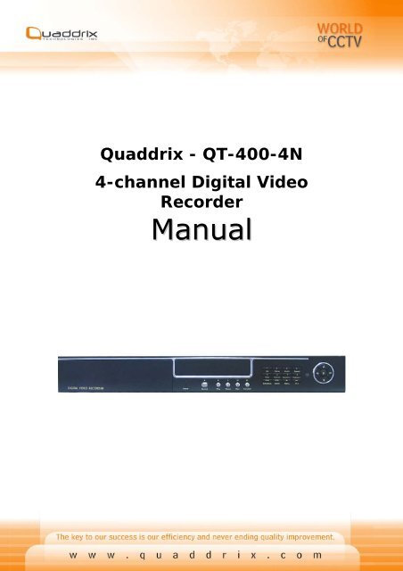
Quaddrix - <strong>QT</strong>-<strong>400</strong>-<strong>4N</strong><br />
4-channel Digital Video<br />
Recorder<br />
<strong>Manual</strong>
Security Notice<br />
• Power supply<br />
This Digital-Video-Recorder applies DC 12 voltage indoor power<br />
supply. The voltage of the power must be verified before using.<br />
When the machine is not in use for a long time, pull out the plug<br />
from the socket and disconnect the power.<br />
• Security<br />
This machine is indoor using equipment; in order to avoid<br />
dangers of short circuit or electric shock, please do not expose<br />
the machine in rain or moist environment. In case any solid or<br />
liquids get into the machine’s case, please cut off the power<br />
supply immediately, and ask for qualified technicians to check<br />
the machine before restart.<br />
This machine is precise instrument; do not attempt to repair<br />
any unit of the machine by yourself without technical aids.<br />
When there is any malfunction with the machine, please ask for<br />
qualified technicians to examine and repair, or contact the<br />
dealers in your area.<br />
• Installation<br />
Please choose appropriate site to install the machine, to ensure<br />
well ventilation around the machine to avoid the machine<br />
excessively hot. The machine cannot be installed near radiator<br />
and ventilating trunk etc. heat sources, or under straight<br />
sunshine, or dusty places or anywhere there is a chance for<br />
mechanical librations or impact.<br />
• Advice<br />
While recording TV programs or VCD programs, please don’t<br />
pirate the third-party’s authority and/or any other relative rights.<br />
Features of this DVR<br />
• Video input: 4channels; video output: 2 channels.<br />
• Audio input: 4channels; audio output: 1 channels.<br />
• Four optional levels of image quality: very high, high, normal,<br />
low. Record and playback frame rate change enable for recording.<br />
• Compression mode: Modified MJEPG.<br />
• Compatible with NTSC and PAL format.<br />
• Support alarm recording and time recording.<br />
• Multi-function searches: be able to distinguish different alarm<br />
records and time records from ordinary records; be able to search<br />
by time, by segment or by event.<br />
• Support various playback modes: pause, several fast forward and<br />
backward play modes.<br />
1
• Support zoom, auto, and PIP function.<br />
• USB backup and update enable<br />
• Equipped with remote device and PTZ control enable.<br />
• Support loss and motion detection functions.<br />
• Support watermark security protect.<br />
• Triplex operation, may play back and search while it is recording.<br />
Both live and playback pictures can be displayed on screen<br />
simultaneously.<br />
• Totally independent from PC platform, thoroughly keeping away<br />
from shutdown caused by inappreciative operations, complicated<br />
management and operation, and virus infection.<br />
2
Table of Contents<br />
SYSTEM SETUP......................................................................5<br />
1. SETUP METHODS OF MENU.........................................................................................................5<br />
2. ACCESS MENU .............................................................................................................................5<br />
3. SYSTEM SETUP ............................................................................................................................6<br />
4. TIME/DATE SET...........................................................................................................................8<br />
5. HDD FORMAT SET ......................................................................................................................9<br />
6. AUTO SEQUENCE SET ...............................................................................................................10<br />
7. FACTORY RESET.........................................................................................................................10<br />
8. VIDEO SETUP.............................................................................................................................11<br />
9. NAME SETUP ..............................................................................................................................11<br />
10. BRI/CON SETUP......................................................................................................................12<br />
11. RECORD SETUP .......................................................................................................................12<br />
12. NETWORK SETUP ....................................................................................................................13<br />
13. MAC SET ..................................................................................................................................14<br />
14. ALARM SETUP..........................................................................................................................15<br />
15. MOTION DETECTION SETTINGS .............................................................................................16<br />
16. AREA SET.................................................................................................................................16<br />
17. USB SET .................................................................................................................................17<br />
18. SCHEDULE SET........................................................................................................................18<br />
19. PROTOCOL SET........................................................................................................................18<br />
BUTTONS ON THE FRONT PANEL .............................20<br />
1.RECORDING/PLAYING CONTROL BUTTONS AREA....................................................................20<br />
2.FUNCTION CONTROL AREA ........................................................................................................21<br />
3.CHANNEL CHOOSING CONTROL AREA......................................................................................23<br />
DISPLAY STATUSES WHILE RUNNING .................24<br />
1.SCREEN DISPLAY WHILE RUNNING ..........................................................................................24<br />
2.SCREEN DISPLAY WHILE PLAYING............................................................................................24<br />
3.TRIP DISPLAY.............................................................................................................................25<br />
SYSTEM CONNECTION....................................................26<br />
1.BACK PANEL AND CONNECTION TERMINALS............................................................................26<br />
2.VIDEO AND AUDIO CONNECTION..............................................................................................27<br />
3.ALARM CONNECTION..................................................................................................................28<br />
4.HARD DISK CONNECTION..........................................................................................................29<br />
USER GUIDELINE...............................................................30<br />
1.START THE MACHINE..................................................................................................................30<br />
2.TURN OFF THE MACHINE............................................................................................................31<br />
3.NORMAL RECORDING .................................................................................................................31<br />
4.ALARM RECORDING....................................................................................................................32<br />
5.TIME RECORDING .......................................................................................................................32<br />
3
6.PLAYBACK ....................................................................................................................................33<br />
7.SEARCH PLAY ..............................................................................................................................34<br />
8.TIME SEARCH..............................................................................................................................34<br />
9.EVENT SEARCH ...........................................................................................................................35<br />
10. START STOP SEARCH..............................................................................................................36<br />
11.ZOOM OPERATION....................................................................................................................37<br />
12.PIP OPERATION........................................................................................................................38<br />
13.INFORMATION DISPLAY............................................................................................................38<br />
14.USB BACKUP............................................................................................................................39<br />
15.PTZ OPERATION ......................................................................................................................40<br />
16.DEFAULT SETTING....................................................................................................................42<br />
17.REMOTE CONTROL ...................................................................................................................43<br />
18.SERIAL PORT CONTROL...........................................................................................................44<br />
EXTERIOR SIZE...................................................................46<br />
INCASE LIST.........................................................................46<br />
APPENDIX A: TROUBLE SHOOTING GUIDE........47<br />
APPENDIX B: SERIAL PORT PROTOCOL...............50<br />
APPENDIX C: RECORD TIME IN FOR 120G<br />
HARD DISK (HOUR) .........................................................53<br />
APPENDIX D: INTERNET VIEW/PLAYBACK<br />
CONFIGURATIONS............................................................54<br />
4
System Setup<br />
Before using the video recorder, the first step is to set up the system<br />
according to user’s needs; otherwise the machine will run with the default<br />
settings.<br />
1. Setup Methods of menu<br />
When in setup mode, push upward button or downward button, the cursor will<br />
move among the settable items, continuous pushing will make the cursor<br />
move among the options one by one, and it can recur. The selected one will<br />
display in yellow color.<br />
While choosing digital fields, e.g. year, month, day, hour, minute, second etc,<br />
push leftward button or rightward button, the cursor can move leftward or<br />
rightward among the several digits of one field, continuous pushing will make<br />
it move among digits one by one, and it can recur.<br />
Please push “+” or “-” button to change the value that the cursor stands,<br />
push ENTER button to enter sub menu and push menu button to return to<br />
previous menu.<br />
2. Access Menu<br />
System setup is achieved through entering menu, and then setting up on<br />
each option’s window. To access the menu, please push menu button on the<br />
front panel, it will display password input window.<br />
The password is a random combination of 4 digits of “0-9”. The default is<br />
“0000”. To enter the menu below, you have to input the correct password by<br />
pushing the digital buttons. If the password you input is incorrect, the system<br />
will automatically return. If you don’t want to input the password but give up<br />
the operation, you can push menu button to return. While inputting the<br />
password, in order to avoid being revealed to stander-bys, the password you<br />
input is displayed on the screen as “*” signs.<br />
5
To change the password, please refer to “password change”.<br />
3. System Setup<br />
When the cursor moves to System Setup, please push enter button, the<br />
System Setup window will appear, which is illustrated as below.<br />
PASSWORD SET<br />
6
PASSWORD CHANGE<br />
Press Enter button to change the password.First,the user should enter the<br />
CURRENT PASSWORD,If the current password is correct,the system will<br />
prompt to input CHANGE PASSWORD and CONFIRM PASSWORD,the twice<br />
input must be the same.If the password is changed successfully,the system<br />
will prompte a phrase—Password changed .<br />
SETUP PASSWORD: “ON ” means that the user should input the password<br />
before entering setup menu. “OFF” means that the uer can enter the setup<br />
menu without password.Use “+” or “-” to modify this option.<br />
SYSTEM PASSWORD: “ON” means that the user should input the password<br />
before entering system. “OFF” means that the user can enter the system<br />
without password. Use “+” or “-” to modify this option.<br />
SCHEDULE PASSWORD: “ON” means that the user should input the<br />
password if he wants to stop schedule recording. “OFF” means that the user<br />
can stop the schedule recording without password. Use “+” or “-” to modify<br />
this option.<br />
RECORD PASSWORD: “ON” means that the user should input the password<br />
if he wants to stop recording. “OFF” means that the user can stop recording<br />
without password. Use “+” or “-” to modify this option.<br />
Note :If you forgotten password ,you can press “stop “ button twelve<br />
times,This operation can change password to default value, The factory<br />
default value is “0000”.if you forgotten password of system start ,when the<br />
system prompts that the password is mistake,you can press “stop ”button<br />
twelve times,This operation can change password to default value .<br />
7
MENU LANGUAGE: Use “+” or “-” to modify this option.<br />
PLAY REPEAT: if you set this to “YES”, when play the video to the end of the<br />
HDD, it will automatically play the video from the beginning of the HDD again.<br />
If set to ‘NO’, it will stop when play to the end.<br />
VIDEO SOURCE: video format, NTSC/PAL<br />
BUZZER SOUND: buzzer switcher, if set to “OFF”, the buzzer will not work..<br />
4. Time/Date Set<br />
When the cursor moves to TIME/DATA SET, please push enter button, the<br />
Time/date setup window will appear, which is illustrated as below. If the DVR<br />
is in recording mode you cannot access to this menu unless you stop record<br />
first.<br />
Please push up, down, left, and right buttons to move the cursor, push add<br />
and DEC button to modify the value.<br />
FORMAT: the time display format, different for USA, EURO and Asia users.<br />
DISPLAY: if set to “OFF”, time will not display no the screen.<br />
LOCAL: time display position.<br />
.<br />
8
5. HDD Format Set<br />
When the cursor moves to HDD FORMAT SET, please push enter button, the<br />
HDD Format Setup window will appear, which is illustrated as below.<br />
If you select “YES” and push the enter button, all video on the HDD will loss,<br />
if you want to give up, please select “NO”.<br />
9
6. Auto Sequence Set<br />
When the cursor moves to Auto Sequence Set, please push enter button, the<br />
Auto Sequence Set window will appear, which is illustrated as below. Here you<br />
can setup the auto sequence time.<br />
7. Factory Reset<br />
When the cursor moves to Factory Reset, please push enter button, the<br />
Factory Setup window will appear, which is illustrated as below.<br />
If you select “YES” and push the enter button, all setting of the DVR will reset<br />
to default, if you want to give up, please select “NO”.<br />
10
8. Video Setup<br />
When the cursor moves to Video Setup, please push enter button, the Video<br />
Setup window will appear, which is illustrated as below.<br />
BOUNDARY: boundary line color<br />
BACK GROUND: back ground color.<br />
9. Name Setup<br />
When the cursor moves to Name Setup, please push enter button, the Name<br />
Setup window will appear, which is illustrated as below.<br />
11
Each channel’s name is the combination of eight characters. Push up or down<br />
button to move cursor and push enter button to select which channel’s name,<br />
then push left or right button to select each character, push ADD or DEC<br />
button to modify each character, and then push enter button to save this<br />
name.<br />
DISPLAY: if set to “OFF”, the channel’s name will not display on the screen.<br />
10. Bri/Con Setup<br />
When the cursor moves to Bri/Con Setup, please push enter button, the<br />
Bri/Con Setup window will appear, which is illustrated as below.<br />
BRI: picture brightness CON: picture contrast<br />
Please push up, down, left, and right buttons to move the cursor, push add<br />
and DEC button to modify the value.<br />
11. Record Setup<br />
When the cursor moves to Record Setup, then push enter button,<br />
the Record Setup window will appear, which is illustrated as below.<br />
Push upward or downward button to move the cursor. Push “+”or “-<br />
” button to change the value. While the DVR is in recording or<br />
playback mode, you can not access to this menu unless you stop<br />
record or play first.<br />
12
OVER WRITE: if set to “YES”, the DVR will automatically overwrite the HDD<br />
from the beginning when the HDD is full. If set to “NO”, the DVR will<br />
automatically stop recording when the HDD is full.<br />
REC SPEED: the recording frame rate of the DVR, factory default setting is<br />
30F/SEC under NTSC (25F/1SEC under PAL), Which means DVR records the<br />
events at the speed of 30 shots of frames per second. The higher of the<br />
record frame rate, the more natural look will be displayed on the screen when<br />
you playback. The lower of the record frame rate, the more you can save the<br />
space on the hard disk. The highest frame rate is 120F/SEC(PAL is 100F/SEC)<br />
when the resolution is in 320 mode<br />
REC QUALITY: There are four different video quality settings: LOW, NORMAL,<br />
HIGH and VERY HIGH. The higher the video quality, the clearer images when<br />
you playback. The lower the video quality, the more you can save the space<br />
on the hard disk drive.<br />
RESOLUTION: the record picture size of the DVR have two modes: 360 and<br />
720,default is 360. In 720 mode, the record picture is twice bigger than in<br />
360 mode, in 320 mode the REC speed is 120F/SEC(PAL is 100F/SEC) and<br />
can not change, the maximal REC speed in 720 mode is 60F/SEC(PAL is<br />
50F/SEC).<br />
PB SPEED: the frame rate of playback, default is NO USE, which means the<br />
same as record.<br />
AUDIO ENABLE: audio select, the DVR has one record channel, you can select<br />
one in four channels, the default is channel one.<br />
Note: The audio playback only had effect on DVR.<br />
12. Network Setup<br />
When the cursor moves to Network Setup, then push enter button, the<br />
network setup menu window will appear, which is illustrated as below. If a PC<br />
Viewer soft from Internet is connected to the DVR. You cannot access this<br />
menu unless you disconnect the PC View.<br />
13
Network STATE: network SPEED switch, if in local network, please select<br />
LOCAL_LAN, if for internet use, please choose EXTER_LAN<br />
NET DATA PORT: the video transmit port for the computer.<br />
NET CMD PORT: the command transmit port for the computer.<br />
If you change any of the VIDEO PORT and COMMAND PORT or MAC<br />
address, you have to restart the DVR to use the “net viewer” software.<br />
13. Mac Set<br />
When the cursor moves to Mac Set then push enter button, the Mac Set<br />
window will appear, which is illustrated as below.<br />
If you have more than one DVR in a local area network, you have to set<br />
each DVR to have an exclusive mac address, but remember that you have<br />
only one chance to modify the mac address, once you have changed the mac<br />
14
address, this menu will not appear again. If you want to change the mac<br />
address again, please load the factory set, then you can change the mac<br />
address again.<br />
14. Alarm Setup<br />
When the cursor moves to Alarm Set, then push enter button, the alarm<br />
setup window will appear, which is illustrated as below. Push upward or<br />
downward button to move the cursor. Push “+” or “-“ to change the value.<br />
CHANNEL SELECT: Choose the channel needed modified.<br />
ALARM ENABLE: alarm trigger switch, can be set to off, low lever or high<br />
lever. If users set it to off, the DVR will ignore the alarm input.The default<br />
setup is OFF.<br />
MOTION ENABLE:Motion alarm switch, can be set to on or off, if set to off,<br />
the motion alarm will be ignored. The default setup is OFF.<br />
MOTION LEVEL: motion sensitivity level,There are five options to<br />
choose:very low,low,normal,high,very high.if the figure in the picture is small,<br />
please set to high or very high, the default is high.<br />
EVENT REC TIME:How long does the DVR record when the motion alarm or<br />
sensor alarm occurs.The default value is thirty seconds.<br />
BUZZER SOUND: buzzer sound time when there is a sensor or motion<br />
alarm.The default value is one second.<br />
SCREEN SWITCH: If the user choose “ON”,when motion or sensor alarm<br />
trigger,the corresponding channel will hold the full screen . “OFF” means that<br />
this function is closed.Use “+” or “-” to modify this option.<br />
Note: Users should press Schedule button after setting up the parameters so<br />
to activate the settings.If the alarm record takes effect,the schedule record<br />
can’t be setted.<br />
15
15. Motion Detection settings<br />
1) When surveying nearby objects (2-10 meters)<br />
When in daytime, please set motion detection sensitivity as Normal level;<br />
when in night, please set as low.<br />
2) When surveying objects in 50-100 meters area<br />
The objects 50-100 meters away will be quite small on the screen. When<br />
in daytime, please set motion detection sensitivity as high level.<br />
When in night as below, please set as normal level.<br />
Note: the above suggestions are from many times’ tests. User can<br />
select the best parameters according to the actual operation<br />
environment.<br />
16. Area Set<br />
When the cursor moves to Alarm Set, then push enter button, the alarm<br />
16
setup window will appear, which is illustrated as below. Please push up, down,<br />
left, right button to move the cursor and push enter button to change, long<br />
push enter change all value the same as you selected.<br />
If one area is set to yellow, this area is motion detected enable, and gray is<br />
disable. So if you want to mask some place, just set these area gray.<br />
17. USB Set<br />
When the cursor moves to USB Set, If you have pluged the USB device into<br />
the DVR, then push enter button, the USB setup window will appear, which is<br />
illustrated as below. push enter button to start update. Before you plug in the<br />
USB device you have to copy update file to USB.<br />
17
USBBACKUP SAVE: There are two types of backup mode: PICTURE and FILM,<br />
in PICTURE mode you can backup picture and in FILM mode you can backup<br />
video.<br />
The backup can only work in playback mode.The USB disk’s max size<br />
supported is 4G.The checked time lies on the its size.<br />
18. Schedule Set<br />
When the cursor moves to Schedule Set, please push enter button, the<br />
schedule set window will appear, which is illustrated as below.<br />
You can change a recording schedule during a week by using this setup, from<br />
Monday to Sunday, you can set a period time each day.<br />
START: start record time STOP: stop record time<br />
Note: <strong>Manual</strong> record mode and schedule record mode (including<br />
motion detection record mode, sensor record mode and time schedule<br />
record mode) cannot be valid at the same time. Once users select<br />
Schedule record mode, manual record mode will invalid; once user<br />
select manual record mode, schedule record mode will be invalid.<br />
19. Protocol Set<br />
When the cursor moves to Protocol Set, then press enter button,<br />
the protocol set window will appear, which is illustrated as below.<br />
Press upward or downward button to move the cursor, and press<br />
“+” or “-“ to change the value.<br />
18
If set the protocol rightly, you can control the SPEED DOME by the DVR, or<br />
control the DVR by a computer or a keyboard.<br />
CHANNEL SEL: Select the channel which is connected to the speed dome you<br />
want to control<br />
BAUDRATE: Changeable form 2<strong>400</strong>bps to 38<strong>400</strong>bps.The default is 2<strong>400</strong>bps.<br />
DOME ADDR: The address of the speed dome, changeable from 0x00 to<br />
0xff。<br />
PROTOCOL SEL: The protocol of speed dome, include pelco-p, pelco-d, neon,<br />
lilin.the default is pelco-p.<br />
DVRPROTOCOL SEL: The protocol is suitable for computer or keyboard to<br />
control the DVR, please refer to appendix B<br />
DVRADDR SEL: The address of the DVR for DVRPROTOCOL, can be changed<br />
from 0x00 to 0xff<br />
DVRADDR SEL: Changeable form 2<strong>400</strong>bps to 38<strong>400</strong>bps.The default is<br />
4800bps.<br />
19
Buttons On the Front Panel<br />
The front view of the video-recorder is illustrated as below.<br />
1.Recording/Playing Control Buttons Area<br />
1.Record: It is manual recording button. Push this button to record<br />
video on hard disk, Re-push this button or push stop button, it will<br />
stop recording (need password). So, this button is the switch button<br />
of manual recording and stopping recording operations. Recording<br />
and stop will work simultaneously on four channels’ images. This<br />
button doesn’t work in schedule mode.<br />
2.Play: Push this button to start playing the video stored in hard<br />
disk, Re-push this button or push stop button, it will stop playing<br />
So, this button is the switch button of playing video and stopping<br />
playing operations. Playing and stop will work simultaneously on<br />
four channels’ images. This button doesn’t work while Time<br />
recording and Alarming recording.<br />
20
3.Pause: Push this button to stop playing temporarily; push play<br />
button to continue to play.<br />
4.Rew: Fast backward button. Push this button to start fast<br />
backward playing till push play button to start normal playing from<br />
the present position.<br />
5.Forward: Fast forward button. Push this button to start fast<br />
forward playing till push play button to start normal playing from<br />
the present position. The fast forward has five speeds; every time<br />
you push the button will change the speed from slow to fast and<br />
then back to slow.<br />
2.Function Control Area<br />
1.Auto/1: Auto key, push this button, The DVR will be in auto dwell state, it<br />
dwells according to the time set in auto sequence set menu, you can set the<br />
dwell time of each channel. Push channel select button to quit this mode.<br />
While inputting numbers, this button is used as number key of “1”.<br />
21
2.PIP/2: PIP key, push this button, the DVR will be in PIP mode, please refer<br />
to PIP operation in user guideline for details, push channel select button to<br />
quit PIP mode. While inputting numbers, this button is used as number key of<br />
“2”.<br />
3. Zoom/3: Zoom key, push this button, the DVR will be in zoom mode,<br />
please refer to zoom operation in user guideline for details, push zoom button<br />
again to cancel zoom operation. While inputting numbers, this button is used<br />
as number key of “3”.<br />
4.Trip/4:Trip key, push trip button, the DVR will be in trip mode, please<br />
refer to trip operation in user guideline for details. While inputting numbers,<br />
this button is used as number key of “4”.<br />
5.Stop/5: Stop key, while recording or playing video, push this button to<br />
stop recording or playing. This button doesn’t work while Time recording and<br />
Alarming recording. While inputting numbers, this button is used as number<br />
key of “5”.<br />
6. Search/6: Search key, push this button to enter search menu, please<br />
refer search play in user guideline for details. While inputting numbers, this<br />
button is used as number key of “6”.<br />
7.WM/7/+: Watermark key, if the DVR is playing video, you can push this<br />
button to see the watermark of the picture, if the video was recorded by this<br />
DVR and has not be changed, there will be a watermark symbol in each<br />
picture, push watermark key again to clear the display. While inputting<br />
numbers, this button is used as number key of “7”, When in system setup<br />
menu, this is an increase button.<br />
8.Display/8/-: Display key, push this button to display current information<br />
on the screen, push again this to clear the information display. While inputting<br />
numbers, this button is used as number key of “8”. When in system setup<br />
menu, this is a decrease button.<br />
9. PTZ/9: Push this button to enter PTZ control state, push once to control<br />
first speeddome, repush to second speeddome, then third, then forth, then<br />
quit PTZ control. While inputting numbers, this button is used as number key<br />
of “9”.<br />
10. USB/0: USB backup button, during playback, push this button to backup<br />
video. While inputting numbers, this button is used as number key of “0”.<br />
11.Menu: Push this button to enter system setup menu, in menu setup<br />
mode, push this button to save settings and quit current menu.<br />
12. Schedule Push this button to enter schedule state, if the DVR is in<br />
schedule state, there will be an “S” symbol on screen, push again this button<br />
to quit schedule mode.<br />
22
3. Channel Choosing Control Area<br />
1.First channel/up: Push this button to see full screen display form channel<br />
1. While selecting menu items, push this button to move up the cursor.<br />
2.Second channel/down: Push this button to see full screen display form<br />
channel 2. While selecting menu items, push this button to move down the<br />
cursor.<br />
3.Third channel/left: Push this button to see full screen display form<br />
channel 3. While selecting menu items, push this button to move the cursor<br />
leftward.<br />
4.Forth channel/right: Push this button to see full screen display form<br />
channel 4. While selecting menu items, push this button to move the cursor<br />
rightward.<br />
5.Quad/enter: Push this button to see all images of 4 channels. While<br />
selecting menu items, push this button to select the item.<br />
.<br />
23
Display Statuses While Running<br />
1.Screen Display While Running<br />
: Means DVR is schedule on. : There is an alarm input.<br />
: Channel 1 has an alarm input. : Channel 1 is audio on.<br />
: DVR is recording video now.<br />
2.Screen Display While Playing<br />
24
: DVR is playing video. : Live picture is loss.<br />
3.TRIP Display<br />
In trip mode, there will be eight pictures on screen, PB CH1~ PB CH4 are<br />
playback pictures, CAM 1~ CAM4 are live pictures.<br />
Push Trip button or channel buttons to exit Trip mode.<br />
25
System Connection<br />
1.Back Panel and Connection Terminals<br />
The power cord and input, output signal terminals are all at the back<br />
of the machine, the connections to monitor, camera etc equipments<br />
are all carried out through the terminals and sockets on the back<br />
panel. The back view of the machine is illustrated as below.<br />
Each part of the back panel is illustrated as below:<br />
26
1 Power 2. Video input 1, 2, 3, 4 3.Video output 4.Audio input<br />
1, 2, 3, 4<br />
5.Audio output 6.USB 7. Net interface 8. Alarm input 9.<br />
Alarm output<br />
10. +5V 11. GND 12. RS485<br />
2.Video and Audio Connection<br />
The DVR can support up to 4 cameras video input at the same time.<br />
VEDIO OUT<br />
VEDIO IN<br />
AUDIO IN<br />
AUDIO OUT<br />
VEDIO IN<br />
Mi cr ophone<br />
There are two steps for camera installation.<br />
.Connect the Video Signal Line to the DVR channel input.<br />
.Connect the power adaptor jack to the camera.<br />
The DVR can connect 4 channel’s audio input, but you can only select<br />
one for recording.<br />
To display the DVR picture, the DVR’s video output signal should be<br />
transferred to your TV set or monitor. Any TV set that has a “video input”<br />
terminal is suitable for displaying the picture. The figure above shows<br />
the video and audio signal line connection.<br />
Note: at one time, you can only connect one audio input,<br />
which means, if you connect an audio to cam1, you cannot<br />
connect any of cam2 to cam 4. You should plug them out.<br />
27
3.Alarm Connection<br />
The DVR can support up to 4 alarm input and three alarm output.<br />
Alarm input: There are two types of alarm input.<br />
1. Voltage output(5V and 0V)<br />
A: In case sensor output high voltage (5V) normally and<br />
output low voltage when triggered (0V), then users must set DVR<br />
as low voltage alarm.<br />
B: In case sensor output low voltage (0V) normally and<br />
output high voltage when triggered (5V), then users must set DVR<br />
as high voltage alarm.<br />
2. Open/Close output<br />
A: N.O. Normal open,close when triggered. DVR must set as<br />
low voltage alarm.<br />
B: N.C. Normal close,open when triggered,DVR must set as<br />
high voltage alarm.<br />
28
Alarm output<br />
There are three alarm output pin, the status of these pin are illustrated as<br />
below<br />
Before alarm<br />
N. O.<br />
COM<br />
N. C.<br />
After alarm<br />
There is an example for alarm output connection<br />
N. O.<br />
COM<br />
N. C.<br />
N. O.<br />
COM<br />
N. C.<br />
Alarm<br />
5V<br />
4.Hard Disk Connection<br />
There are several steps to install the hard disk.<br />
Note: If the DVR comes with a HDD, skip the following steps.<br />
29
1. Pull out the hard drive rack from the<br />
DVR side panel.<br />
2. Open the top cover of the drawer.<br />
3. Jump HDD to Master<br />
4. Connect the ribbon cable (IDE) cable<br />
& power cable.<br />
Jump to Master<br />
5. Close the top cover of the drawer and<br />
put the hard drive drawer back into the<br />
DVR. (Make sure the cables are firmly<br />
pressed onto the HDD interface)<br />
6. Lock the hard drive draw by turning<br />
the key clockwise.<br />
If you have another HDD, please jump that HDD to SLAVE, and open the<br />
machine, put the HDD to the HDD shelf, and then connect the power and digit<br />
cable.<br />
User Guideline<br />
1.Start the Machine<br />
Before starting the machine, please make sure all the items in the<br />
“Security Notice” at the beginning of this manual are fulfilled.<br />
Before starting the machine, please check the system connection,<br />
input and output equipment connection.<br />
Please insure the video-recorder’s input video (NTSC/PAL) and the<br />
monitor (NTSC/PAL) meet the demands.<br />
30
Start exterior equipment after checking over.<br />
Insert the removable hard disk case to the end, and lock it up (turn<br />
right the hard disk lock); connect the power, the machine start to<br />
work.<br />
2.Turn off the Machine<br />
Normally turn off the machine when the system shutdown, which<br />
means do not to turn off the machine while playing or system setting<br />
up, especially not to turn off the machine while recording<br />
Push recording button to stop recording or push playing button to<br />
stop playing or exit from system setup menu, then turn off the<br />
power.<br />
If do not use the video recorder for a long time, should pull out the<br />
power line from the electrical outlet.<br />
3.Normal Recording<br />
Connect the power to all related equipments; ensure that there is<br />
video input.<br />
Push display button to check spare space of the hard disk, if there is<br />
no much space, please think whether to change hard disk first or<br />
select overwriting modes.<br />
Check recording parameter setup before recording; select video<br />
quality, frame rate. you cannot change record setting during the<br />
process of recording.<br />
<strong>Manual</strong> recordings belong to normal recording. Under the manual<br />
mode (non-schedule status), here pushing record button will record<br />
all channels’ image video.<br />
Push the record button to begin recording, four channels will start<br />
simultaneously recording. While in normal recording mode, push<br />
record or stop button, and enter the right password, it will stop<br />
recording.<br />
During the process of recording, if the hard disk is full, and the<br />
system is set to automatic overwrite, then the recording will not be<br />
interrupted, and it begins to overwrite from the earliest recorded<br />
area; if the system is set to overwrite disable, it will stop recording.<br />
31
4.Alarm Recording<br />
Alarm recording is not started by manually pressing record button.<br />
Alarm recording can be activated by alarm input signal or motion, so<br />
it must to check whether the connection of alarm input equipment is<br />
correct, stable and reliable, and the alarm set is right, please refer to<br />
sensor setup.<br />
The prerequisite condition of whether the alarm recording can be<br />
activated by exterior input signal or the motion is the system must<br />
be set on schedule, also, in the menu of alarm setup, for exterior<br />
input alarm, alarm enable of that channel must set to “ON”, for<br />
motion alarm, motion enable of that channel must set “ON”, and set<br />
the area you want for motion detection.<br />
Under the state of off-schedule, system will never start alarm<br />
recording. Please note setting schedule on or off is achieved through<br />
pressing the schedule button on the front panel, not through system<br />
setup menu and window. Under schedule-on situation, the character<br />
“S” will display on the screen.<br />
Alarm video recording cannot stop by pressing record button, but<br />
can stop by removing schedule. Because once the system is set on<br />
schedule, the schedule cannot be removed randomly, there is a<br />
password protection to remove schedule, only after inputting correct<br />
password, you can take schedule off.<br />
Check alarm recording setup before recording; confirm the video<br />
quality and the frame rate, the record setting cannot change during<br />
recording process.<br />
As long as the alarm input signal is effective, the alarm recording<br />
continues. When the alarm input signal loses efficacy, the time set<br />
up by “A/M REC TIME” becomes effective, and when the time goes<br />
by, the alarm recording automatically stops. In course of this, if you<br />
want to manually stop alarm recording, the only way is to remove<br />
schedule (answer the password).<br />
5.Time Recording<br />
Time recording starts and stops recording automatically according to<br />
the pre-arranged time period. It is applied to fixed timetable, for<br />
32
example, the periodical work time recording (or off time recording)<br />
with fixed start/stop time.<br />
To start Time recording function, Make record schedule setup<br />
beforehand, and press down the schedule button on the front panel<br />
to set schedule on. While pressing down this button, the schedule<br />
symbol “S” will display on the screen. Without pressing the schedule<br />
button, the Time recording parameter setup will not work.<br />
The prerequisite condition of whether the time recording takes<br />
effective is system must be set according to schedule.<br />
In time record state, you can press again schedule button then enter<br />
password to stop time recording.<br />
Because Time recording is correlated closely with time, so before<br />
using this function, should previously adjust the time.<br />
6.Playback<br />
Press play button,system begins to play the images recorded<br />
In the process of playing, press pause button to pause playing, repressing<br />
play button can continuously play.<br />
In the process of fast forward playing or fast backward playing,<br />
pressing press play button will begin normal playing from the current<br />
one.<br />
Continuous pressing forward button will change the fast-forward<br />
among five levels of speed (X2, X4, X8, X16, X32) circularly.<br />
Continuous pressing backward button will change the fast backward<br />
among four levels of speed (X2, X4, X8, X16) circularly.<br />
During playback mode, long press single frame button will play<br />
backward frame by frame, long press single frame forward button<br />
will play forward frame by frame. Press play button to play normally.<br />
Press play button again will stop playing.<br />
33
7.Search Play<br />
Push search button,search play window will display on the screen.<br />
TIME SEARCH: search play by input time.<br />
EVENT SEARCH: search play by event list.<br />
START STOP SEARCH: search play by segment.<br />
Press upward and downward button to move cursor, then press<br />
enter button to enter sub menu you select, press menu button to<br />
quit from search menu.<br />
8. Time Search<br />
When the cursor moves to Time Search, then push enter button,<br />
the time search window will appear, which is illustrated as below.<br />
34
Push leftward and rightward button to move the cursor, push<br />
add and DEC button to modify the time, then push enter button<br />
to start play from the time you enter. Push menu button back to<br />
Search Play menu.<br />
If the time you enter has no play video, the DVR will<br />
automatically play the video most close to the time you enter.<br />
START: the first time you record, END: the end time of<br />
recording, you must enter right time between start and end. If<br />
the HDD has been overwritten, the start time maybe not correct.<br />
If you have two HDD, and both of the HDD have video data,<br />
push search button to change the HDD.<br />
9. Event Search<br />
When the cursor moves to Event Search, then press enter button,<br />
the event search window will appear, which is illustrated as below.<br />
There are four types of event list: MOTION, ALARM, SCHEDULE and<br />
NETWORK. MOTION means motion alarm recording, Alarm means<br />
sensor alarm recording, SCHEDULE means time recording,<br />
NETWORK means network recording<br />
Press upward and downward button to move the cursor among the<br />
event list, press leftward and rightward button to see previous or<br />
next page, press enter button to play the segment you select.<br />
35
Press menu button back to Search Play menu.<br />
If you have two HDD, and both of the HDD have video data,<br />
push search button to change the HDD.<br />
10. Start Stop Search<br />
When the cursor moves to Start Stop Search, then press enter<br />
button, the Start stop search window will appear, which is<br />
illustrated as below.<br />
All record segments are displayed here, press upward and<br />
downward button to move the cursor among the segment list,<br />
press leftward and rightward button to see previous or next page,<br />
press enter button to play the segment you select. Press menu<br />
button back to Search Play menu.<br />
36
If you have two HDD, and both of the HDD have video data,<br />
push search button to change the HDD.<br />
11.Zoom Operation<br />
Push zoom button, the DVR will be in zoom mode, which is<br />
illustrated as below. Push upward, downward, leftward or rightward<br />
to move the zoom area, then push enter button to zoom, push zoom<br />
button again to cancel zoom operation.<br />
37
12.PIP Operation<br />
Push PIP button, the DVR will be in PIP mode, which is illustrated as<br />
below.<br />
You can push again PIP button to change PIP mode, long press<br />
PIP button can set each PIP picture. Long press PIP button, when<br />
one channel name is in yellow, push left and right button to change<br />
selected channel, push add and DEC button to change this channel’s<br />
picture, push enter button to cancel this mode, push channel select<br />
button to quit PIP mode.<br />
13.Information Display<br />
If you push display button, the main information of the DVR will<br />
display on screen.<br />
38
HDD MODEL: HDD type<br />
HDD MAX: the size of the hard disk you insert to the DVR.<br />
HDD USED: the usage of the hard disk. OVERWRITE: hard disk<br />
overwrite enable.<br />
REC SPEED: record frame rate speed. QUALITY: record picture<br />
quality.<br />
RESOLUTION: record resolution.<br />
the DVR.<br />
IP ADDRESS: IP address of<br />
14. USB Backup<br />
Plug in the USB device, go to the menu of USB set, check whether<br />
the USB device was detected, and the free space of the USB device<br />
is enough, select the backup mode, then quit the menu setup.<br />
Backup is available only in playbak mode.<br />
if you select “STILL” for the backup mode in the Backup Set menu,<br />
press the USB button, it begin to backup the main out picture to the<br />
USB device, there will be a “S” on the screen, when it disapear, the<br />
backup of the picture is done, you can plug the USB device out and<br />
see the picture on a computer with the net viewer soft.<br />
If you select “MOVIE” for the backup mode in the USB Set menu,<br />
press the USB button, it begin to backup the main out video to the<br />
39
USB device from the moment, press USB button again to select the<br />
end of the backup video, there will be a “A” on the screen. This may<br />
take a little time, and make sure the USB device has enough free<br />
space, if the “A” disapear, the backup is ok, you can see the video<br />
on a computer with net viewer software.<br />
NOTE: if you backup still picture, please choose full picture display.<br />
15.PTZ Operation<br />
This DVR can control all speeddomes which are connected to the<br />
DVR.<br />
To control the speeddome, make sure all the lins are correctly<br />
connected, first you must set the right protocol, baud rate, and<br />
speeddome’s address, please refer to protocol set.<br />
For example, you connect the first speeddome to channel one, you<br />
have to make sure that the baud rate, the protocol, and<br />
speeddome1’s address is the same as the speeddome you connect to<br />
the channel.<br />
Now you can control the speeddome, push the PTZ button, the<br />
character “PTZ CAM 1” will appear on the screen, that means you<br />
are now controlling the speeddome connected to channel one. Push<br />
the button again to control the speeddome that connect to the<br />
channel two, the character “PTZ CAM 2” will appear on the screen,<br />
the same to channel three, channel four. Then push the PTZ button<br />
one more time to exit from PTZ control.<br />
During the PTZ control state, you can push upward, downward,<br />
leftward, rightward button to move the speeddome, and push the<br />
enter button to stop. If you push the Iris button, the character “Iris”<br />
will appear on the screen, then you can push the “+” and “-” button<br />
to change the iris, the same to control the focus, zoom, and speed,<br />
also push enter button to stop.<br />
Other functions will not work untill you cancel the PTZ control state.<br />
40
16. Default Settings<br />
Default setting for each item is shown in the below chart.<br />
“Defaults” is the initial setup by the manufacturer. User can change<br />
the setup according to the actual environment and demands. If<br />
there is any confusion or unexpected effect, choose “Defaults” and<br />
readjust.<br />
You can choose “FACTORY RESET” in “SYSTEM SET” menu, and<br />
reset all settings to default setting.<br />
S<br />
Y<br />
S<br />
T<br />
E<br />
M<br />
S<br />
E<br />
T<br />
U<br />
P<br />
Setup<br />
window<br />
for each<br />
item<br />
General<br />
setting<br />
Recording<br />
Para<br />
Net Work<br />
Setting<br />
Alarm<br />
setting<br />
Setup items<br />
Default<br />
setup<br />
Selectable setup<br />
Year/Month/Day/<br />
Hour/Minute<br />
2005/01//01<br />
12/00/00<br />
2000~2099/Common sense<br />
rules<br />
Auto Time 1 second 0~99second<br />
Buzzer Sound ON ON/OFF<br />
Password 1111 N/A<br />
Play Repeat YES YES/NO<br />
Video Input NTSC format NTSC/PAL<br />
Quality Normal Very high/High/Normal/Low<br />
Overwrite Enable YES YES/NO<br />
Rec Speed<br />
30f/s(NTSC)<br />
25f/s(PAL)<br />
Resolution 360 360/720<br />
60f/s~1f/2s(NTSC)<br />
50f/s~1f/2s(PAL)<br />
PB Speed NO use<br />
60f/s~no use(NTSC)<br />
50f/s~no use(PAL)<br />
Audio Enable CAM 1 CAM1~CAM4/OFF<br />
A/M REC Time 1 Minute 0~99minute<br />
Sub Net 255.255.255.0 N/A<br />
Gate Way 192.168.1.1 N/A<br />
IP Address 192.168.1.167 N/A<br />
Net Work State LOCAL_LAN LOCAL_LAN / EXTER_LAN<br />
N/W Enable ON ON/OFF<br />
Mac Address 0a0b0c0d0e0f N/A<br />
Alarm Enable OFF ON/OFF<br />
Motion Enable OFF ON/OFF<br />
Motion Level Normal<br />
Very low/Low/<br />
Normal/High/Very high<br />
Buzzer Sound No Use 0~99 second<br />
Protocol Baud Rate 2<strong>400</strong> 2<strong>400</strong>/4800/9600/19200/38<strong>400</strong><br />
42
Setting<br />
Protocol PTC1 PTC1/ PTC2/ PTC3/ PTC4<br />
Address 01 0~0xff<br />
17. Remote Control<br />
All the function of the DVR can be operated by the remote<br />
device.<br />
43
18.Serial Port Control<br />
To control the DVR through the RS485 or control the speed dome,<br />
you have to make sure the protocol and baud rate is right, please<br />
refer to appendix B.<br />
44
Main standard & parameter chart<br />
Item<br />
Specification<br />
Video signal<br />
Video input<br />
NTSC/PAL<br />
Composite:1.0V p-p/75Ω,BNC×4<br />
Video output<br />
Composite:1.0V p-p/75Ω,BNC×2<br />
Audio input<br />
-8Db 22KΩ, RCA connector×4<br />
Audio output<br />
-8Db 3KΩ, RCA connector×1<br />
Alarm input 4<br />
Alarm output 1<br />
Compression<br />
standard<br />
Record time<br />
Electron clock<br />
Modified MJPEG<br />
18-1680 hours/40G<br />
Year/Month/Day;Hour/Minute/Second<br />
Secrete function<br />
Power source<br />
Power<br />
Environment<br />
temperature<br />
Exterior size<br />
Weight<br />
Password protection<br />
DC12V<br />
25W<br />
Work Temperature:+5~+50;humidity:<<br />
90%<br />
Store Temperature:-20~+70;humidity:<<br />
95%<br />
432×55×286mm<br />
About 3.2Kg<br />
45
Exterior size<br />
432mm<br />
55mm<br />
70mm<br />
AUTO ZOOM PIP TRIP<br />
STOP SEARCH WM/+DISPLAY/-<br />
MENU SCHEDULE<br />
POWER REC PLAY PAUSE<br />
REW FORWARD<br />
286mm<br />
Incase list<br />
Incase list<br />
Name<br />
Quantity<br />
4-channel hard disk video recorder 1<br />
Remote device 1<br />
Power wire 1<br />
Keys to removable hard disk control lock 2<br />
User guideline 1<br />
In case of any question, please do not hesitate to contact the dealer<br />
directly.<br />
46
Appendix A: Trouble shooting guide<br />
Q. What kind of camera should I buy for this DVR?<br />
A. Any BNC or RCA interface indoor/outdoor/infrared camera will work<br />
with the DVR. It doesn’t matter whether it’s a color or black/white<br />
camera. However, web cameras that require a USB interface are not<br />
compatible with the DVR.<br />
Q. What kind of alarm device should I buy for DVR?<br />
A. Most sound alarms are compatible with our DVR.<br />
Q. I can’t turn on DVR.<br />
A. Make sure that the power cord is plugged in correctly and the red<br />
power light on DVR front panel is on.<br />
Q. I see nothing but a blue screen after I turn on DVR.<br />
A. Check the camera input and video output connection on DVR back<br />
panel. If you can’t find problem with these connections, check whether the<br />
camera power cable is firmly connected. Make sure the system format for<br />
NTSC and PAL is right.<br />
Q. I see a fatal error message on the screen.<br />
A. If you see the error messages such as “System fatal error is occurred”,<br />
pull out and put in the hard disk drive or replace the hard disk. Also make<br />
sure that hard disk rack is firmly locked. Otherwise, replace the hard disk.<br />
Q. Can I prevent other people from stopping the recording while I am<br />
gone?<br />
A. If the DVR is in schedule or recording mode, no one can change the set<br />
unless he has the right password.<br />
Q. How can I erase all data on the hard disk drive?<br />
A. Select “HDD Format Set” option on the menu.<br />
Q. I forgot my password. What should I do?<br />
47
A. Press the “1234” when entering password and it will reset DVR’s<br />
password to factory default. Then the password will reset to factory<br />
default (0000).<br />
Q. Can my desktop PC read the video data on hard disk drive in DVR?<br />
A. Yes, you can use our software to read all video data on hard disk.<br />
Q. What happens if I install my PC hard disk drive into the DVR?<br />
A. You can use a PC hard disk drive in the DVR. However, once it runs in<br />
DVR, it will delete any PC operation system and files on the hard disk<br />
drive.<br />
Q. What kind of hard disk drive should I purchase to make the DVR run?<br />
A. Any PC compatible IDE, ATA hard disk drive will work.<br />
Q. Does this DVR kit come with sensors, cameras, or hard disk drive?<br />
A. No. You have to buy each accessory separately.<br />
Q. What is the capacity to record?<br />
A. Up to a year with two 120 GB HDD at the lowest quality setting when<br />
set at 1 frame per second.<br />
Q. Does this DVR come with a remote control either hardwire or wireless?<br />
A. Yes, there is a remote control come with the DVR.<br />
Q. Can I control the DVR with a computer or a keypad?<br />
A. Yes, you can use a computer or a keypad to control the DVR through<br />
the RS485 port.<br />
Q. Why cannot I access Time/Date Set, HDD Format Set, Record Set<br />
menu?<br />
A. Please stop record or play before you access these menu.<br />
Q. Why cannot I access Network Set menu?<br />
A. Please stop the connection of the PC View soft from Internet before you<br />
access Network Set menu.<br />
Q. I push record button, but the DVR does not start recording, why?<br />
48
A. Push display button to see if there is a hard disk detected, also if the<br />
DVR is in schedule mode (there is a “S” on the screen in yellow), you<br />
cannot start recording by push record button, you have to push schedule<br />
button again to cancel schedule mode.<br />
Q. I push stop button, but the DVR does not stop recording, why?<br />
A. If the DVR is recording in schedule mode (there is a “S” on screen),<br />
you cannot stop recording unless you quit schedule mode first. Push<br />
schedule button to cancel schedule mode.<br />
Q. There is a movement, but the DVR does not start recording.<br />
A. Make sure the motion enable of that channel is on, the area set is ok,<br />
the A/M rec time is not set to off, and the DVR is in schedule mode.<br />
Otherwise set the motion level to HIGH or VERY HIGH.<br />
Q. When the network connection between DVR and client computer is cut<br />
off, why the DVR halts and clock stops?<br />
A: In case network is cut off abnormally, DVR machine will halts for 20<br />
seconds without response to any operation of pressing front panel<br />
buttons. 20 seconds later, it will restore normal state, but the icon that<br />
shows network status won't disppear in 10 minutes and in this period<br />
client computer cannot connect to the DVR or enter network menu.<br />
Q. How much HDD size dose this DVR support?<br />
A. Any type size of the HDD is OK to the DVR, but if the size is much more<br />
then 300G, it may display only 300G on the DVR, and it does not effect<br />
the real size use on the DVR.<br />
49
Appendix B: serial port protocol<br />
Serial port setting: BAUD, n, 8, 1 (BAUD =2<strong>400</strong>,4800,9600,19200,38<strong>400</strong>)<br />
PTC1: (three byte)<br />
Command<br />
HAR)<br />
Hexadecimal<br />
Number<br />
Function<br />
Description<br />
/RE 0x2F 0x52 0x45 Record<br />
/TP 0x2F 0x54 0x50 Play<br />
/PE 0x2F 0x50 0x45 Pause<br />
/RT 0x2F 0x52 0x54 Reward<br />
/FT 0x2F 0x46 0x54 Forward<br />
/FS 0x2F 0x46 0x53 Auto/1<br />
/FS 0x2F 0x5A<br />
Zoom/2<br />
0x4D<br />
/ZM 0x2F 0x50 0x50 PIP/3<br />
/RS 0x2F 0x52 0x53 Trip/4<br />
/SP 0x2F 0x53 0x50 Stop/5<br />
/SH 0x2F 0x53 0x48 Search/6<br />
/QY 0x2F 0x51 0x59 Water mark/7/+<br />
/DY 0x2F 0x44 0x59 Display/8/-<br />
/SE 0x2F 0x53 0x45 PTZ/9<br />
/FF 0x2F 0x46 0x46 USB/0<br />
/AF 0x2F 0x41 0x46 Menu<br />
/SC 0x2F 0x53 0x43 Schedule<br />
/01 0x2F 0x30 0x31 Ch1/up<br />
/02 0x2F 0x30 0x32 Ch2/down<br />
/03 0x2F 0x30 0x33 Ch3/left<br />
/04 0x2F 0x30 0x34 Ch4/right<br />
/22 0x2F 0x32 0x32 Chall/enter<br />
PTC2: (seven byte)<br />
Transmitting Transmitting Instructions<br />
S.N<br />
worth<br />
Byte1 0x03 Fixed byte<br />
50
Byte2 0xaa DVR identifier word<br />
Byte3 0x01 Fixed byte<br />
Byte4 Device id DVR device address<br />
Byte5~7<br />
Refer to PTC<br />
1<br />
Same command as<br />
PTC 1<br />
PTC3: (seven byte)<br />
Byte1 Byte2 Byte3 Byt4 Byte5 Byte6 Byte7<br />
0xFF Addr Var1 Var2 Check<br />
sum<br />
Var1 Var2 Function PELCO-<br />
D<br />
0x00 0x08 Ch1/up Up<br />
0x00 0x10 Ch2/down Down<br />
0x00 0x04 Ch3/left Left<br />
0x00 0x02 Ch4/right Right<br />
0x04 0x00 Chall/enter Iris<br />
close<br />
0x00 0x40 Record Zoom<br />
wide<br />
0x00 0x20 Play zoom<br />
tele<br />
0x02 0x00 Search Iris<br />
open<br />
0x00 0x80 WM/+ Focus<br />
far<br />
0x01 0x00 Display/- Focus<br />
near<br />
Byte 5 and byte 6 are ransom value from 0x00 to 0xff.<br />
Byte 7 = mod [(byte2 + byte3 + byte4 + byte5 + byte6)/100]<br />
Note: This protocol is the same as PELCO-D, which is used to control<br />
speed dome. So, if you use PELCO-D to control speed dome by a<br />
keyboard, you can also use the keyboard to control the DVR through this<br />
protocol, we can use different address to distinguish the DVR and the<br />
speed dome.<br />
51
PTC4: (eight byte)<br />
Byte1 Byte2 Byte3 Byte4 Byte5 Byte6 Byte7 Byte8<br />
0xa0 Addr 0x00 0x07 0x00 Var 0xAF Checksum<br />
Byte8 = byte1 xor byte2 xor byte3 xor byte4 xor byte5 xor byte6<br />
xor byte7<br />
Var Function Var Function<br />
0x01 Ch1/up 0x0C Schedule<br />
0x02 Ch2/down 0x0D 0/USB<br />
0x03 Ch3/left 0x0E 1/auto<br />
0x04 Ch4/right 0x0F 2/zoom<br />
0x05 Chall/enter 0x10 3/PIP<br />
0x06 record 0x11 4/trip<br />
0x07 Play 0x12 5/stop<br />
0x08 Pause 0x13 6/search<br />
0x09 Reward 0x14 7/WM/add<br />
0x0A Forward 0x15 8/display/DEC<br />
0x0B Menu 0x16 9/PTZ<br />
Note: This protocol is the same as PELCO-P’s call function; you can use<br />
PELCO-P’s call function to control the DVR. First, you must set right<br />
protocol, baud rate and address, second, you push call button on the<br />
keypad, then push the number according to Var above, last push enter<br />
button.<br />
52
Appendix C: record time in for 120G hard disk (hour)<br />
Rec rate<br />
field/sec<br />
Picture<br />
quality<br />
Resolution Recording<br />
time<br />
60 fps Very high 720 22.5 hours<br />
60 fps Low 720 60 hours<br />
120 fps Normal 360 22.5 hours<br />
1 fps Normal 720 2160 hours<br />
Note: The above figures are from our test results. Just for users’<br />
reference. Different definition and stabilization (objects’<br />
movement) of the images will make some kind of different results.<br />
53
Appendix D: Internet View/Playback Configurations<br />
1. About Network<br />
Users can select the following types of networks:<br />
1): Local Area Network (LAN): telecom companies offer the Internet<br />
connection, e.g. optical fiber, and users of a community/building setup<br />
Internet server, then put cables into the end user’s office/home through<br />
HUB.<br />
2): ADSL: user applies for ADSL from Internet services supplier and get<br />
an ADSL MODEM, and then connect the computer to the ADSL MODEM, by<br />
inputting user name and password in the dialing software users can<br />
connect to Internet.<br />
3): Close Circuit Television Broadband: users applies for CCTV<br />
connection from CCTV services supplier, and connect a computer to a<br />
CABLE MODEM to surf online.<br />
4): In companies or Internet cafes, network administrators utilize routers<br />
or proxy server to connect all the computers to one Internet cable, and all<br />
the computers use the same Internet IP address. Most companies are<br />
using this kind of network nowadays.<br />
54
ADSL Modem<br />
ISP<br />
Internet<br />
Ro u te r<br />
Sw ic t h e r<br />
LAN<br />
COMPANY<br />
ADSL Modem<br />
ISP<br />
Internet<br />
HOME<br />
2. Network Configurations<br />
After connecting to Internet, our DVR card users should make the<br />
following configurations to make remote view/playback.<br />
1): When in LAN, network administrators should open the following ports<br />
for specifics computers: 5000- 5002. Please make sure that the other<br />
services don’t use the same ports.<br />
2): In case users use ADSL network and the surveillance system computer<br />
connect to the ADSL MODEM, then the ports have all opened by default. If<br />
not, please close fire wall by guidance of the ADSL MODEM user’s manual.<br />
3): In case connect to Internet by proxy server, users should utilize port<br />
mapping software and open ports 5000 –5002 for the surveillance<br />
computer.<br />
4): In case users connect to Internet by router, then users should add the<br />
IP address of the surveillance computer and open the abovementioned<br />
55
ports in DMZ setup or Virtual Server setup (the names maybe different in<br />
different kind of routers) of the router.<br />
5): For CABLE MODEM type and ADSL MODEM type, the configurations are<br />
some kind of the same:<br />
56
As ADSL and CABLE MODEM network users usually use dynamic IP<br />
address, so once the MODEM restarts, the IP addresses will change. For<br />
this situation, users should apply for DNS services.<br />
58