QT-400-4N Manual
QT-400-4N Manual
QT-400-4N Manual

Create successful ePaper yourself
Turn your PDF publications into a flip-book with our unique Google optimized e-Paper software.
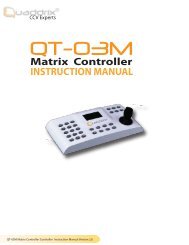
1 Power 2. Video input 1, 2, 3, 4 3.Video output 4.Audio input<br />
1, 2, 3, 4<br />
5.Audio output 6.USB 7. Net interface 8. Alarm input 9.<br />
Alarm output<br />
10. +5V 11. GND 12. RS485<br />
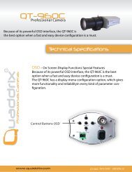
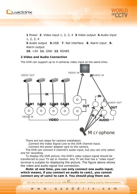
2.Video and Audio Connection<br />
The DVR can support up to 4 cameras video input at the same time.<br />
VEDIO OUT<br />
VEDIO IN<br />
AUDIO IN<br />
AUDIO OUT<br />
VEDIO IN<br />
Mi cr ophone<br />
There are two steps for camera installation.<br />
.Connect the Video Signal Line to the DVR channel input.<br />
.Connect the power adaptor jack to the camera.<br />
The DVR can connect 4 channel’s audio input, but you can only select<br />
one for recording.<br />
To display the DVR picture, the DVR’s video output signal should be<br />
transferred to your TV set or monitor. Any TV set that has a “video input”<br />
terminal is suitable for displaying the picture. The figure above shows<br />
the video and audio signal line connection.<br />
Note: at one time, you can only connect one audio input,<br />
which means, if you connect an audio to cam1, you cannot<br />
connect any of cam2 to cam 4. You should plug them out.<br />
27