quaddrix zeus ii series dvr stand alone - Quaddrix Technologies
quaddrix zeus ii series dvr stand alone - Quaddrix Technologies
quaddrix zeus ii series dvr stand alone - Quaddrix Technologies

Create successful ePaper yourself
Turn your PDF publications into a flip-book with our unique Google optimized e-Paper software.
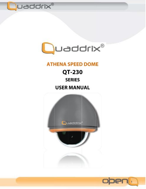
ATHENA SPEED<br />
DOME<br />
QT-230<br />
SERIES<br />
USER MANUAL<br />
1
TABLE OF CONTENTS<br />
1. Welcome ......................................................................................................................................................................................... 3<br />
2. DECLARATION ............................................................................................................................................................................... 3<br />
3. INSTALLATION PREPARATION ................................................................................................................................................ 5<br />
4. INSTALLATION TYPE GUIDE ..................................................................................................................................................... 6<br />
5. In-Ceiling Mount .......................................................................................................................................................................... 7<br />
6. Surface Mount ............................................................................................................................................................................ 12<br />
6 Install Pan/Tilt module and black liner .............................................................................................................................. 14<br />
NOTE: Check if it is tightly installed. ................................................................................................................................... 15<br />
7. Wall Mount (for screw thread connection base) ........................................................................................................... 16<br />
8. Wall Mount(for convexity connection base) ................................................................................................................... 19<br />
9. Pole Mount ................................................................................................................................................................................... 23<br />
10. Pendant Mount .......................................................................................................................................................................... 24<br />
11. Parapet Mount ............................................................................................................................................................................ 26<br />
12. System connection .................................................................................................................................................................... 27<br />
13. Operation ...................................................................................................................................................................................... 28<br />
14. Menu tree ..................................................................................................................................................................................... 29<br />
15. MENU OPERATION .................................................................................................................................................................... 30<br />
16. System setup ............................................................................................................................................................................... 31<br />
17. Lens parameters ........................................................................................................................................................................ 34<br />
18. Camera Parameters ................................................................................................................................................................. 35<br />
19. Pan Tilt .......................................................................................................................................................................................... 37<br />
20. Function Setting ....................................................................................................................................................................... 38<br />
21. Privacy Mask ............................................................................................................................................................................... 42<br />
22. Appendix I: DIP Switch & Jumper Settings ..................................................................................................................... 43<br />
23. Appendix II: Wire Diameter & Transmission Distance Comparison Chart .......................................................... 48<br />
24. Appendix III: RS485 Bus Basic Knowledge ...................................................................................................................... 49<br />
25. Appendix IV: Lightning Proof & Surge Proof .................................................................................................................. 51<br />
26. Appendix V: The Cleaning of Down Cover...................................................................................................................... 51<br />
27. Appendix VI: Trouble Shooting ........................................................................................................................................... 52<br />
2
1. Welcome<br />
Thank you for using our high speed dome. This state-of-the-art speed dome will fulfill your wide range professional security<br />
surveillance need.<br />
Features:<br />
• 80 “presets tour”, 4 sequences with up to 30 presets each, 4 patterns with min. 180 seconds each, 4 autoscans,8 regions.<br />
• Auto running, runs the assigned function automatically after a period of idling.<br />
• l Up to 8 privacy masks.<br />
• With dome, preset, pattern, autoscan and region titles, the titles can be set to not display, display or display for a period<br />
• of time.<br />
• Powerful OSD menu, all the functions can be set via OSD menu.<br />
• With RS485, Manchester, Bi-phase or Coaxitron control interface, support, VCL, PELCO-P, PELCO-D, PELCO-C,<br />
PHILIPS, VICON, KALATEL, AMERICAN DYNAMICS, MOLYNX, PANASONIC etc. protocols.<br />
• Built in DSP camera, with auto focus, auto BLC, auto light control, auto white balance etc. functions.<br />
• Color/mono auto, manual or switch at a set time. (for day/night models).<br />
• With 4000V video, data, power lightning proof and surge proof.<br />
• Hi-accuracy motor drives with 0.5 degree preset accuracy, min. 0.5 degree moving without any vibration.<br />
• 360 degrees continuous pan, 90 degree tilt with auto flip.<br />
• IP66 <strong>stand</strong>ardized for outdoor speed dome.<br />
2. DECLARATION<br />
This equipment has been tested and found to comply with the limits for a Class A digital device, pursuant to part 15 of<br />
FCC rules and European Union 89/336/EEC directive and its latest amended version. These limits are designed to<br />
provide reasonable protection against harmful interference when the equipment is operated in a commercial environment.<br />
This equipment generates, uses, and can radiate radio frequency energy and, if not installed and used in accordance with<br />
the instruction manual, may cause harmful interference to radio communications. Operation of this equipment in a<br />
residential area is likely to cause harmful interference in that case the user will be required to correct the interference at<br />
his own expense. Modifications not expressly approved by <strong>Quaddrix</strong> <strong>Technologies</strong> could void the user’s authority to<br />
operate the equipment under CE and FCC rules.<br />
Precautions:<br />
1. Only qualified and experienced person can carry on this installation.<br />
2. Always conform to national and local safety codes during installation.<br />
3. Use reliable tools only, poor quality tools may cause danger. e.g. ladder.<br />
4. Do install the speed dome to appropriate environment (Refer to the chart below). This product conforms to IP66<br />
<strong>stand</strong>ardas specified in “Housing Protection Classification (IP code)”.<br />
5. Check the space and toughness of the site before installing. It should be able to bear 4 times the weight of the dome<br />
andits accessories.<br />
6. Keep all the original dome package materials in case of future repacking and transportation.<br />
3
Warnings:<br />
1. DO NOT install this speed dome in hazardous places where combustible or explosive materials are stored or used.<br />
2. DO NOT install indoor dome in outdoor environment.<br />
3. This speed dome runs on 24V AC. DO NOT connect higher or lower voltage to it.<br />
4. DO NOT turn power on before completing installation.<br />
5. DO NOT disassemble any part of the items.<br />
6. Use soft towel to clean the down cover when necessary. DO NOT use caustic detergent.<br />
7. To protect CCD, avoid facing the camera to direct strong light. e.g the sun.<br />
4
3. INSTALLATION PREPARATION<br />
5
4. INSTALLATION TYPE GUIDE<br />
6
5. In-Ceiling Mount<br />
7
Installation requirements:<br />
5.1. The thickness of the ceiling should be less than<br />
42mm<br />
5.2. The ceiling should be able to bear 4 times the<br />
weight of the speed dome.<br />
5.3. Upper space should be at least 20cm high.<br />
1. Draw a circle on ceiling<br />
Determine the installation position and draw a circle on<br />
the ceiling according to the accessory paper pattern. The<br />
paper pattern’s diameter is 225mm. NOTE: there are<br />
two kinds of pan/tilt modules available as the left picture<br />
illustrated. The user should be aware of the differences<br />
of two pan/tilt modules during the installation.<br />
2 Cut circle off<br />
Use a saw or proper tool to cut off the circle.<br />
NOTE: MAKE SURE the diameter of the circle is<br />
225+2mm before cutting the circle off.<br />
8
6 Install housing:<br />
Push housing into ceiling and let the clips stretch out.<br />
Finally, screw the three clips to tighten the housing<br />
NOTE: Use even strength to adjust the three clips,<br />
otherwise it may distort the shape of the housing.<br />
7 Set dome ID, baud rate and protocol<br />
Set dome ID, baud rate and protocol via DIP switches.<br />
10
8 Install Pan/Tilt module and black liner<br />
Take down the key ring (1) from connection bridge in<br />
the housing and button hole (2) on the base board with<br />
the key ring. Loosen two screws (3) and match them<br />
with two guidance holes on the base board. Then push<br />
dome module upward and turn it anticlockwise to the<br />
end. Fasten screws (3) . Plug RJ45 connector into the<br />
socket on the power board of the dome module. Push the<br />
black liner into the two locking tabs.<br />
NOTE: When the dome module is installed, please turn<br />
on the power to make sure the dome module is in good<br />
condition.<br />
9 Install down cover<br />
Fix the safety chain on housing. The safety chain<br />
prevents the down cover from dropping down. Match<br />
the clasps and mounting holes, and then turn the down<br />
cover frame widdershins.<br />
NOTE:<br />
Let the safety chain inside the arc groove of the down<br />
cover, otherwise it may scratch the lens. l If you find it<br />
difficult to fit in the down cover, try to readjust the three<br />
clips.<br />
11
6. Surface Mount<br />
Installation requirements:<br />
1. The ceiling should be hard and solid.<br />
2. The ceiling should be able to bear 4 times the weight<br />
of the speed dome.<br />
NOTE: there are two kinds of pan/tilt modules available<br />
as the left picture illustrated. The user should be aware<br />
of the differences of two pan/tilt modules during the<br />
installation.<br />
6. 1 Detach down housing<br />
Turn down housing anticlockwise and pull down the<br />
down housing.<br />
12
6.2 Mark screws positions<br />
Using the surface mount base as a template to mark the<br />
fastener positions on the ceiling, and then drill 3 holes.<br />
6.3 Install the surface mount base<br />
Pass the Power/RS485/Video cables through the central<br />
hole of surface mount base and fix them on the ceiling.<br />
NOTE: Wires can be also passed through the side hole<br />
of surface mount base.<br />
6.4 Connect the cables<br />
Insert cables into corresponding sockets on connection<br />
board. After completing cable connection, turn on the<br />
power. The red LED will light up. Turn off the power<br />
after checking. If the red LED is not lit up, check the<br />
cable connection. The dome can be set for either coaxial<br />
or twisted- pair communication through DIP switch as<br />
shown in the following illustration.<br />
NOTE:<br />
Please MAKE SURE power is off before doing<br />
connection. Two video transmission interfaces are<br />
available on the dome. Please connect video cable with<br />
the corresponding interface as your Requirement.<br />
13
6.5 Set dome ID, baud rate and protocol<br />
Set dome ID, baud rate and protocol via DIP switches.<br />
6.6 Install Pan/Tilt module and black liner<br />
Take down the key ring from connection bridge in<br />
the housing and button hole on the base board with<br />
the key ring.<br />
Loosen two screws and match them with two guidance<br />
holes on the base board. Then push dome module<br />
upward and turn it anticlockwise to the end. Fasten<br />
screws . Plug RJ45 connector into the socket on the<br />
power board of the dome module. Push the black liner<br />
into the two locking tabs.<br />
NOTE: When the dome module is installed, please turn<br />
on the power to make sure the dome module is in good<br />
condition.<br />
14
Install down housing<br />
Match the tabs of down cover into the slots and turn<br />
anti-clockwise so as to fix the down housing.<br />
NOTE:<br />
Check if it is tightly installed.<br />
15
7. Wall Mount (for screw thread connection base)<br />
Installation requirements:<br />
The wall mounting surface must be firm enough to bear<br />
4 times the weight of the speed dome.<br />
NOTE: there are two kinds of pan/tilt modules available<br />
as the left picture illustrated. The user should be aware<br />
of the differences of two pan/tilt modules during the<br />
installation.<br />
1 Mark screws positions Take the bracket base as<br />
the template to mark the screws’ positions on the wall,<br />
and then drill the holes to insert expansion screws.<br />
16
5 Set dome ID, baud rate and protocol<br />
Set dome ID, baud rate and protocol via DIP switches<br />
(please refer to APPENDIX I ).<br />
6 Install Pan/Tilt module and black liner<br />
Take down the key ring from connection bridge in the<br />
housing and button hole on the base board with the key<br />
ring. Loosen two screws and match them with two<br />
guidance holes on the base board. Then push dome<br />
module upward and turn it anticlockwise to the end.<br />
Fasten screws . Plug RJ45 connector into the socket on<br />
the power board of the dome module. Push the black<br />
liner into the two locking tabs.<br />
NOTE: When the dome module is installed, please turn<br />
on the power to make sure the dome module is in good<br />
condition.<br />
Install down cover<br />
Loosen the two M4 screws on the down cover ring.<br />
Apply lubricant to the O-ring to make the down cover<br />
easier to slip in. Push upward the down cover into the<br />
housing and then fasten down cover with two M4<br />
screws.<br />
18
8. Wall Mount(for convexity connection base)<br />
Installation requirements:<br />
The wall mounting surface must be firm enough to bear<br />
4 times the weight of the speed dome.<br />
NOTE: there are two kinds of pan/tilt modules available<br />
as the left picture illustrated. The user should be aware<br />
of the differences of two pan/tilt modules during the<br />
installation.<br />
1 Mark screws positions<br />
Take the bracket base as the template to mark the<br />
screws’ positions on the wall, and then drill the holes to<br />
insert expansion screws.<br />
19
2 Install bracket<br />
Pass the Power/RS485/Video cables through the cavity of the<br />
bracket, and then install bracket on the wall.<br />
3 Install convertor assembly<br />
Please unfasten the M4 screw on wall mount bracket at first.<br />
Wrapping enough tape around the convertor, then rotate it to<br />
the bracket tightly.<br />
If the rotation is in difficult processing, you can rotate it after<br />
inserting a cross-head screw driver with the diameter of 6mm<br />
into the hole of the convertor (not the screw thread hole).<br />
Tighten the M4 screw at last.<br />
NOTE: You can pass this step directly if the assembly is<br />
installed already.<br />
4 Install housing<br />
Please fix the security lock to its corresponding position<br />
at first, then connect the power cable, video cable, and<br />
control cable with no mistake (please cover the bare<br />
metal part of BNC with a rubber pipe after the<br />
connecting of video cable). Pass those cable connectors<br />
upward into the bracket, push the three bulges on the<br />
connection base into three relevant grooves of the<br />
convertor to the top place, then rotate it till it reaches the<br />
top. The last step is to tighten the M5 screw.<br />
20
Install Pan/Tilt module and black liner. Take down the<br />
key ring from connection bridge in the housing and<br />
button hole on the base board with the key ring. Loosen<br />
two screws and match them with two guidance holes on<br />
the base board. Then push dome module upward and<br />
turn it anticlockwise to the end. Fasten screws . Plug<br />
RJ45 connector into the socket on the power board of<br />
the dome module. Push the black liner into the two<br />
locking tabs.<br />
NOTE: When the dome module is installed, please turn<br />
on the power to make sure the dome module is in good<br />
condition.<br />
7 Install down cover<br />
Loosen the two M4 screws on the down cover<br />
ring.Apply lubricant to the O-ring to make the down<br />
cover easier to slip in. Push upward the down cover into<br />
the housing and then fasten down cover with two M4<br />
screws.<br />
22
9. Pole Mount<br />
Installation requirements:<br />
The outside diameter of the pole must be in the range of<br />
130-150mm (5.12 ~6 inches).<br />
NOTE: there are two kinds of pan/tilt modules available<br />
as the left picture illustrated. The user should be aware<br />
of the differences of two pan/tiltmodules during the<br />
installation.<br />
1 Install base<br />
Mount the pole adaptor to the pole with two mounting<br />
clamps. Pass the Power/RS485/Video cables through the<br />
central hole of the bracket base, and then fix them<br />
around the pole.<br />
2 Install bracket<br />
Pass the cables through the cavity of bracket and fasten<br />
bracket on the base.<br />
3 Install convertor assembly<br />
NOTE: This installation is only for the convexity<br />
connection base.<br />
4 Install housing<br />
5 Connect cables<br />
6 Set dome ID, baud rate and protocol<br />
7 Install Pan/Tilt module and black liner<br />
8 Install the down cover<br />
23
10. Pendant Mount<br />
Installation requirements:<br />
The ceiling must be firm enough to bear 4 times the<br />
weight of the speed dome.<br />
NOTE: there are two kinds of pan/tilt modules<br />
available as the left picture illustrated. The user should<br />
be aware of the differences of two pan/tilt modules<br />
during the installation.<br />
1 Mark screws positions<br />
Take the bracket base as the template to mark the<br />
screws positions on the wall, and then drill the holes<br />
to insert expansion screws.<br />
24
2 Install base<br />
Pass the Power/RS485/Video cables through the central<br />
hole of the bracket base, and then fix them on the<br />
ceiling.<br />
NOTE: Apply silicon along the top of bracket base in<br />
the case of outdoor dome.<br />
3 Install suspender<br />
Put the cables through the cavity of the suspender, wind<br />
the waterproof tape to the thread,screw the thread pipe<br />
ahead into the bracket base and finally tighten the M4<br />
screw.<br />
NOTE: Apply silicon to the suspender as shown in the<br />
left illustration in the event of outdoor dome.<br />
4 Install convertor assembly<br />
NOTE: This installation is only for the convexity<br />
connection base.<br />
5 Install housing<br />
6 Connect cables<br />
7 Set dome ID, baud rate and protocol<br />
8 Install Pan/Tilt module and black liner<br />
9 Install the down cover<br />
25
11. Parapet Mount<br />
Installation Requirements:<br />
The wall mounting surface must be firm enough to bear<br />
4 times the weight of the speed dome.<br />
NOTE: there are two kinds of pan/tilt modules available<br />
as the left picture illustrated. The user should be aware<br />
of the differences of two pan/tilt modules during the<br />
installation.<br />
11.1 Mark screws’ positions<br />
Take the bracket base as the template to mark the<br />
screws’ positions on the wall, and then drill the holes to<br />
insert expansion screws.<br />
11.2 Install base<br />
Tighten the M8 expansion screws to secure the bracket<br />
base on the wall .<br />
11.3 Install pipe arm<br />
Put the cables through the two trays of the base and pipe<br />
arm, and then plug the pipe arm into two trays.<br />
11.4 Install convertor assembly<br />
NOTE: This installation is only for the convexity<br />
connection base.<br />
11.5 Install housing<br />
11.6 Connect cables<br />
11.7 Set dome ID, baud rate and protocol<br />
11.8 Install Pan/Tilt module and black liner<br />
11.9 Install the down cover<br />
11.10 Fix pipe arm<br />
Adjust the pipe arm to the proper place, and then fix it to<br />
the base with the two metal hoops.<br />
26
12. System connection<br />
27
13. Operation<br />
28
14. Menu tree<br />
29
15. MENU OPERATION<br />
Selecting item<br />
In the main menu, the cursor flashes on the left, move the joystick up or down to move the cursor to the desired setting<br />
item. Move the joystick to the right to select the item. Select an item to access its sub-menu, or run a specific function, or<br />
change its value, or edit its title. Changing values Move the joystick up or down to change the value, move the joystick to<br />
the left to save the setting and to exit. In the case of more than one value, move the joystick left or right to select place,<br />
move up or down to change value. Move the joystick to the leftmost to save the setting and to exit.<br />
Note: To increase the value changing speed, hold the joystick in up or down position for more than 10 seconds.<br />
A: SITE INFORMATION It uses to set dome ID, title, and broadcast.<br />
B: DISPLAY CONFIGURATION The dome title, preset title, autoscan title, and zoom title can be displayed on the<br />
monitor screen via the settings.<br />
C: CHANGE PASSWORD The default password is “ 000000”, and the password protection function can be closed or<br />
modified.<br />
D: FACTORY DEFAULT It enables all current settings to return to the default settings.<br />
E: SYSTEM RESTART It means that all current operations are stopped and the settings are returned to the initial settings<br />
that were active when the power was turned on.<br />
F: ABOUT It is initial information. You can view dome S/N, dome ID, braut rate, protocol, dome model, software<br />
version.<br />
30
16. System setup<br />
31
17. Lens parameters<br />
OFF: Never restore auto focus. That means focus is always in manual mode.<br />
001-255: The dome will start auto focus in the number of seconds that<br />
have been set (001 to 255) after user adjusts focus manually .<br />
Note: The camera might not be able to auto focus in the following<br />
conditions:<br />
1) Target is not in the center of image.<br />
2) Near and far targets in the same picture can not be both clear.<br />
3) Target is an object with strong light, such as spotlight etc.<br />
4) Target is behind the glass with water drop or dust.<br />
2.1 Zooming Speed 5) Target moves too fast.<br />
The following zooming speed can be selected for the lens:<br />
HIGH: High zooming speed<br />
LOW: Low zooming speed<br />
6) Target is large area such as wall.<br />
7) Target is too dark or vague.<br />
8) Joystick Auto set Off or Joystick Auto set Iris, or Focus is set OFF.<br />
2.2 Focus Limit: 2.6 A/I Recover Time<br />
Set a minimum distance from the lens, the camera will not focus on objects<br />
in that distance. E.g. This feature can prevent camera from focusing on the<br />
down cover.<br />
2.3 Max Digital Zoom<br />
Digital zoom magnifies the picture by duplicating pixels. The picture is<br />
enlarged but the resolution remains the same. This menu item sets max.<br />
digital zoom magnification times.<br />
OFF : Turn off digital zoom<br />
X12 : Max. digital zoom times<br />
Different camera has different Max. digital zoom times.<br />
Light passes through the iris and reaches CCD to form an image. A larger<br />
iris lets more light pass through which enables the image more bright. Iris<br />
can be controlled automatically or manually. For manual operation detail,<br />
please refer to keyboard or matrix manual.<br />
The setup is used to restore auto Iris function after Iris has been adjusted<br />
manually.<br />
OFF: Never restore auto iris. That means iris is always in manual mode.<br />
001-255: The dome will start auto iris in the number of seconds that have<br />
been set (001 to 255) after user adjusts iris manually.<br />
2.7 Day/Night Mode<br />
2.4 Joystick Recover To set the dome color/monochromen switching mode. Color mode is<br />
To set automatically restoring mode. When the joystick moves, the<br />
selected function will start. Function options are:<br />
ALL : Joystick movement triggers both auto focus and auto iris. (default<br />
Focus : Joystick movement triggers auto focus only.<br />
Iris: Joystick movement triggers auto iris only.<br />
None: Joystick movement triggers none of the functions.<br />
appropriate to work in daytime because it needs higher illumination. On<br />
the contrary, light sensitivity of mono mode is much higher. It fits working<br />
at night in low illumination environment but the video is black and white.<br />
Auto: The dome will change modes automatically in<br />
accordance with the environment illumination.<br />
Day: The dome is always in colorful mode.<br />
2.5 A/F Recover Time Night: The dome is always in monochrome mode.<br />
System default of Auto Focus is to adjust automatically the focus to get<br />
clear image.<br />
Focus can also be controlled manually by key board or matrix. For manual<br />
operation details, please refer to keyboard or matrix operation manual. The<br />
Note: You need to set exposure mode to“Auto” in order to get Auto<br />
Day/Night mode.<br />
Note: Iris PLC, IRF Control, Day Mode Time can only be set in certain dome<br />
models.<br />
setup is used to restore auto focus function after focus has been adjusted<br />
manually.<br />
34
18. Camera Parameters<br />
35
19. Pan Tilt<br />
37
20. Function Setting<br />
38
21. Privacy Mask<br />
42
22. Appendix I: DIP Switch & Jumper Settings<br />
43
Dome address setting<br />
The control commands contain target dome’s ID. The<br />
dome only reacts to the command sent to its own<br />
address or broadcast address. So, each dome should be<br />
assigned an address. Four kinds of IDs are applicable for<br />
domes:<br />
l Hard ID: Hard ID is set via DIP SW1, it can not be<br />
changed from OSD menu. Hard ID ranges from 1 to<br />
255.<br />
Programmable ID: Set all 8bits of SW1 to ON to<br />
activate programmable address. Input 10-bit camera SN<br />
number, and then set dome ID by controller(The dome<br />
SN number can be found on the side of the camera or on<br />
the package.).<br />
Debug ID: Set all the bites of the SW1 to 0 (all OFF),<br />
the dome will react to any command for any ID.<br />
NOTE: Debug ID only works with FACTORY<br />
protocol.<br />
Broadcast ID: When a command is sent to broadcast<br />
ID, all domes connected to the control bus will respond<br />
to that command. Broadcast ID is definable, ranges from<br />
1 to 255, the default broadcast ID is 255. SW1 is used<br />
for seting dome ID. The setting is strictly in accordance<br />
with binary system, if you are not familiar with binary<br />
system please look up the address setting chart.<br />
NOTE: When using Philips protocol, the first 5 bits of<br />
SW2 and all bits of SW1 are for address setting. Max<br />
address can be 8191. Example: in order to set address<br />
2657, set bit 1, 6, 7 of SW1 and bit 2, 4 of SW2 ON.<br />
(2657=1+32+64+512+2048)<br />
44
23. Appendix II: Wire Diameter & Transmission Distance Comparison Chart<br />
The transmission distance listed below are farthest ones recommended for each given wire diameter when the 24V AC<br />
voltage loss ratio is below 10% (for equipment powered by AC, the allowed maximum voltage loss ratio is 10%).For<br />
example, a set of equipment with nominal power as 80VA, installed 35 feet (10m) away from transformer, needs a wire<br />
with a minimum diameter of 0.8000mm.<br />
48
Appendix III: RS485 Bus Basic Knowledge<br />
49
24. Appendix IV: Lightning Proof & Surge Proof<br />
The product adopts TVS lightning proof technology to<br />
prevent from damage by lightning strike below 4000V<br />
and impulse signals such as surge; but it is also<br />
necessary to abide by the following precautions to<br />
ensure electrical safety based on practical<br />
circumstances: Keep the communication cables at least<br />
50 meters away from high voltage equipment or cables.<br />
Make outdoor cable laying-out under eaves as possible<br />
as you can. In open area shield cables in steel tube and<br />
conduct a single point ground to the tube. Trolley wire is<br />
forbidden in such circumstances.In strong thunderstorm<br />
or high faradic zone (such as high voltage transformer<br />
substation), extra strong lightning proofe quipment must<br />
be installed.<br />
Take the building lightning proof requirements into<br />
account to design the lightning proof and grounding of<br />
outdoor equipment and cable laying-out in accordance<br />
with the national and industrial <strong>stand</strong>ards.<br />
The system must be grounded with equal potentials. The<br />
earth ground connection must satisfy the antinterference<br />
and electrical safety requirements and must not short<br />
circuited with high voltage electricity net. When the<br />
system is grounded separately, the impedance of down<br />
conductor should be less than 4 Ohms and the sectional<br />
area of down conductor should be greater than 25<br />
square mm (refer to following picture).<br />
25. Appendix V: The Cleaning of Down Cover<br />
To obtain constant clear videos, user should clean the down cover periodically. Be cautious when cleaning. Hold the down cover ring<br />
only to avoid direct touch to the acrylic down cover. The acid sweat mark of fingerprint will corrode the coating of down cover and<br />
scratch on down cover will cause vague images. Use soft dry cloth or the substitute to clean the inner and outer surfaces. For hard<br />
contamination, use neutral detergent. Any cleanser for high grade furniture is applicable.<br />
51
26. Appendix VI: Troubleshooting<br />
52