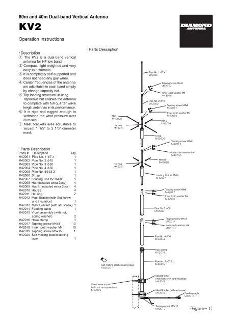
80m and 40m Dual-band Vertical Antenna KV2
80m and 40m Dual-band Vertical Antenna KV2
80m and 40m Dual-band Vertical Antenna KV2

Create successful ePaper yourself
Turn your PDF publications into a flip-book with our unique Google optimized e-Paper software.
<strong>80m</strong> <strong>and</strong> <strong>40m</strong> <strong>Dual</strong>-b<strong>and</strong> <strong>Vertical</strong> <strong>Antenna</strong><br />
<strong>KV2</strong><br />
Operation Instructions<br />
Description<br />
The <strong>KV2</strong> is a dual-b<strong>and</strong> vertical<br />
antenna for HF low b<strong>and</strong>.<br />
Compact, light weighted <strong>and</strong> very<br />
easy to assemble.<br />
It is completely self-supported <strong>and</strong><br />
does not need any guy wires.<br />
Center frequencies of the antenna<br />
are adjustable in each b<strong>and</strong>simply<br />
by change capacity hat.<br />
Top loading structure utilizing <br />
capacitive hat enables the antenna<br />
to complete with full quarter wave<br />
length antennas in its performance.<br />
It is rigid <strong>and</strong> rugged enough to<br />
withst<strong>and</strong> the wind pressure over<br />
35m/sec.<br />
Mast brackets area adjustable to<br />
accept 1 1/5" to 2 1/3" diameter<br />
mast.<br />
Parts Description<br />
Parts # Description<br />
Qty<br />
M42001Pipe No. 1 7.4 1<br />
M42002 Pipe No. 2 10 1<br />
M42003 Pipe No. 3 30 1<br />
M42004 Pipe No. 4 30 1<br />
M42005 Pipe No. 533.2 1<br />
M42006 S trap 1<br />
M42007 Loading Coil for 7MHz 1<br />
M42008 Hat (included extra 2pcs) 4<br />
M42009 Hat S (included extra 2pcs) 4<br />
M42010 Hat SS 4<br />
M42011 Hat ring 2<br />
M42012 Mast Bracket(with Set screw<br />
<strong>and</strong> insulation) 1<br />
M42013 Mast Bracket (with set screw) 1<br />
M42014 Feeding cable 1<br />
M42015 V volt assembly (with nut,<br />
spring washer) 2<br />
M42016 Hose clamp 1<br />
M42017 Tapping screw M4x8 10<br />
M42018 Inner tooth washer M4 10<br />
M42019 Tapping screw M5x15 1<br />
M42020 Self melting plastic sealing<br />
tape 1<br />
Parts Description<br />
Hat<br />
<br />
Hat ring<br />
<br />
Hat ring<br />
<br />
Pipe No. 1 7.4<br />
<br />
Pipe No. 2 10<br />
<br />
S trap<br />
<br />
Tapping screw M4x8<br />
<br />
Inner tooth washer M4<br />
<br />
Hat S<br />
<br />
Hat SS<br />
<br />
Tapping screw M4x8<br />
<br />
Inner tooth washer M4<br />
<br />
Loading Coil for 7MHz<br />
<br />
Pipe No. 3 30<br />
<br />
Pipe No. 4 30<br />
<br />
Tapping screw M4x8<br />
<br />
Inner tooth washer M4<br />
<br />
Tapping screw M4x8<br />
<br />
Inner tooth washer M4<br />
<br />
Tapping screw M4x8<br />
<br />
Inner tooth washer M4<br />
<br />
Hose clamp<br />
<br />
Self melting plastic sealing tape<br />
<br />
Pipe No. 533.2<br />
<br />
V volt assembly<br />
(with nut, spring washer)<br />
<br />
Mast Bracket<br />
(with Set screw <strong>and</strong> insulation)<br />
<br />
Mast Bracket (with set screw)<br />
<br />
Feeding cable<br />
<br />
Tapping screw M5x15
-Note-----------------------------<br />
<br />
Don't install on a rainy or windy<br />
day since it is dangerous.<br />
If the <strong>KV2</strong> is located on the roof of<br />
a house or top of a building, look<br />
around the roof to see if there are<br />
any obstacles such as an electronic<br />
wire or TV antenna. The <strong>KV2</strong> has<br />
to be located as far away as<br />
possible from those things to<br />
obtain its maximum performance.<br />
Installing the antenna too close to<br />
the building wall may cause bad<br />
effect for electrical characteristics<br />
of the antenna.<br />
Don't install the antenna where is<br />
easily reachable by people.<br />
Install the antenna firmly not to fall<br />
down due to the strong wind.<br />
Even if falling down the antenna,<br />
locate the antenna at the safe<br />
place where people <strong>and</strong> building<br />
are not inflicted injures.<br />
<br />
Transmit after confirming if the<br />
antenna works normally by an<br />
SWR meter. If VSWR is less than<br />
1.5, it is no problem. If VSWR is<br />
higher, stop transmitting <strong>and</strong> check<br />
if the parts of the antenna <strong>and</strong><br />
coaxial cable are connected. If<br />
there are tall buildings or obstacles<br />
or the distance between the antenna<br />
<strong>and</strong> the ground is short, VSWR<br />
may not be lowered.<br />
Diamond <strong>Antenna</strong> SWR/POWER<br />
meter is an insertion type being<br />
connected between a transmitter<br />
<strong>and</strong> an antenna. Transmitting<br />
power <strong>and</strong> SWR can be measured<br />
with very simple operations. In<br />
addition with those conventional<br />
measurements, PEP (peak envelope<br />
power) on SSB mode can be<br />
measured with a PEP monitor<br />
function. With our Diamond's<br />
wideb<strong>and</strong> <strong>and</strong> low insertion loss<br />
directional coupler those<br />
measurements can be performed<br />
with minimum effect in<br />
transmission line.<br />
<br />
Touching the antenna during<br />
transmission may cause to electrify.<br />
Pay attention not to touch the<br />
antenna especially for children if<br />
installing on a balcony railing.<br />
<br />
The thunder seems to rumble in<br />
the vicinity, don't touch the<br />
antenna <strong>and</strong> coaxial.<br />
When you don't use the radio, take<br />
off the cable from the radio.<br />
<br />
Keeping transmitting with high<br />
VSWR may cause the radio to be<br />
damaged.<br />
Stop transmitting immediately <strong>and</strong><br />
check the following matters. If it<br />
doesn't solve the problem, please<br />
ask the dealer or Diamond<br />
<strong>Antenna</strong> Corporation.<br />
[Condition: If the antenna doesn't seem<br />
to receive well or propagate well]<br />
Check 1:Is the antenna too close to<br />
the building wall? If the<br />
obstacles are too close to<br />
antenna, VSWR is higher<br />
<strong>and</strong> the radiation pattern is<br />
disturbed. Please install the<br />
antenna from the building<br />
as far away as possible.<br />
Check 2:Did you assemble the<br />
antenna correctly? Please<br />
read the instruction again<br />
<strong>and</strong> reconfirm the assembly.<br />
Check 3:Is the coaxial cable something<br />
wrong? Please check if<br />
soldering the connector is<br />
okay <strong>and</strong> the wire breaks by<br />
the volt-ohm meter.<br />
・Note for selecting adequate<br />
antenna installation location<br />
<strong>and</strong> pre-install preparations.<br />
Since the <strong>KV2</strong> requires good earth<br />
ground to work efficiently, install<br />
the antenna on place where good<br />
earth ground can be obtained.<br />
2A mast to install the antenna has<br />
to be driven in firmly into the<br />
ground or castled into concrete<br />
basis to fix the antenna.<br />
3An earth ground has to be located<br />
as close as possible to the antenna.<br />
Locating the earth ground remote<br />
from the antenna may worsen<br />
electric characteristics of the antenna.<br />
・Assembly Instruction<br />
1Assemble the upper narrow<br />
element first. Prepare Pipe No. 1,<br />
Pipe No. 2, S trap, loading coil for<br />
7MHz, Pipe No. 3, <strong>and</strong> Pipe No. 4.<br />
Assemble them refereeing to the<br />
figure. Screw tapping screw with<br />
inner tooth washer in each<br />
connection part <strong>and</strong> fix them firmly.<br />
2Attach Hat, Hat S, <strong>and</strong> Hat SS on<br />
Hat ring. Attach two Hats <strong>and</strong> two<br />
Hat S on top (3.5MHz) oppositely.<br />
Attach four Hat SS on lower parts.<br />
First, screw them by h<strong>and</strong>. After<br />
that, fix them by spanner firmly.<br />
Hat rings are set at center<br />
frequency at each b<strong>and</strong> in the factory.<br />
3Remove hose clamp from Pipe<br />
No. 5. Insert two mast brackets<br />
<strong>and</strong> fix them as the figure. Make<br />
Pipe No. 5 vertical. (Set up mast at<br />
appropriately 50cm from the ground.<br />
<br />
Placing mast too high causes<br />
characteristic degradation.) When<br />
fixing mast brackets, don't bring<br />
mast brackets into contact with<br />
tapping screw fro fixing feeding<br />
cable. Distance between two mast<br />
brackets must be placed 20-30cm.<br />
Mast<br />
V volt assembly<br />
(with nut,spring washer)<br />
Tapping screw<br />
M5x15<br />
Earth<br />
Tranceiver<br />
Hose clamp<br />
Pipe No.5 33.2<br />
Mast Bracket<br />
(with Set screw <strong>and</strong> insulation)<br />
2530cm<br />
Mast Bracket<br />
(with set screw)<br />
VSWR<br />
meter<br />
Earth cable<br />
Earth<br />
(Figure-2)<br />
4Attach the feeding cable on the<br />
lower part of Pipe No. 5 with<br />
tapping screw.<br />
Insert the element pipe that is<br />
already assembled into about<br />
10cm from above of Pipe No. 5.<br />
Fix it with hose clamp.<br />
Connect earth cable from the<br />
feeding cable to ground earth at<br />
shortest distance. Cut the earth<br />
cable if it is too long.<br />
At last, connect coaxial cable to<br />
MJ connector <strong>and</strong> waterproof with<br />
self melting plastic sealing tape.<br />
・Adjustment<br />
<br />
Practice the following adjustment<br />
procedure at the place where the<br />
antenna is actually installed.<br />
Test transmission for the adjustment<br />
has to be performed for as short time<br />
as possible <strong>and</strong> with as low RF<br />
power as possible. Maximum RF<br />
power rating of continuous wave<br />
(CW) is about 1/3 of it in SSB mode.<br />
Prepare suitable VSWR meter for<br />
operating frequencies <strong>and</strong> output<br />
RF power. Then connect it as<br />
shown in below.<br />
<strong>KV2</strong><br />
<br />
MJ-connector<br />
Feeding cable
Adjustment procedure can be<br />
started from higher frequency<br />
(7MHz). Transmit at desired<br />
frequency <strong>and</strong> change the location<br />
<strong>and</strong> length of hat to have lowest<br />
VSWR at the frequency.<br />
・ Resonant frequency<br />
variations by capacity hat<br />
location <strong>and</strong> hat element length<br />
combinations.<br />
Please refer to the following chart to<br />
find out changes in resonant<br />
frequency b<strong>and</strong>width by capacity hat<br />
location <strong>and</strong> hat element length<br />
combinations. By changing the hat<br />
location up <strong>and</strong> down, resonant<br />
frequency of the antenna changes<br />
within selected variable resonant<br />
frequency b<strong>and</strong>width.<br />
Capacity hat location <strong>and</strong> the hat<br />
length combinations chart.<br />
Combinations Frequency range Frequency<br />
Hat 4pcs 3.4503.515MHz 3.5MHz<br />
Hat 2pcs + Hat S 2pcs<br />
(St<strong>and</strong>ard) 3.5153.575MHz <br />
Hat S 4pcs<br />
Hat S 2pcs +<br />
3.5953.665MHz <br />
Hat SS 2pcs<br />
Hat SS 4pcs<br />
Hat SS 2pcs<br />
Hat S 2pcs<br />
Hat SS 4pcs<br />
(St<strong>and</strong>ard)<br />
3.6603.720MHz<br />
3.7253.770MHz<br />
3.7653.810MHz<br />
7.007.05MHz<br />
7.057.10MHz<br />
<br />
<br />
<br />
7MHz<br />
<br />
Hat SS 2pcs<br />
No Hat<br />
7.107.15MHz<br />
7.157.20MHz<br />
<br />
<br />
・Resonant frequency change<br />
corresponding to the value of the<br />
hat movement.<br />
In 3.5MHz b<strong>and</strong>, approximately<br />
10KHz per 4.5cm movement.<br />
In 7MHz b<strong>and</strong>, approximately 10KHz<br />
per 6.5cm movement.<br />
<br />
<br />
<br />
<br />
<br />
<br />
・<br />
1.5<br />
1.4<br />
1.3<br />
1.2<br />
1.1<br />
3.5 -15 f0 +15<br />
7 -45 f0 +45<br />
MHz KHz<br />
KHz<br />
It may be changed depending on<br />
installation requirements.<br />
・Specifications<br />
Frequency range80, 40 m<br />
(3.5, 7 MHz)<br />
Impedance50Ω<br />
VSWRLess than 1.5<br />
Maximum power rating<br />
250W SSB (3.5MHz)<br />
500W SSB (7 MHz)<br />
Maximum wind resistance35m/sec<br />
Length6.14m<br />
Weight2.65kgs<br />
ConnectorMJ<br />
Mast diameter accepted<br />
1 1/5" - 2 1/3"<br />
(30-62)<br />
Design<strong>Dual</strong> b<strong>and</strong> trap vertical<br />
antenna with trap radials<br />
Though these products purchased<br />
are manufactured under strict quality<br />
control, if damage is caused by<br />
transporting, ask your dealer promptly.<br />
Moving the hat upward will change<br />
resonant frequency of the antenna<br />
higher, <strong>and</strong> down ward will change<br />
the frequency lower. For change<br />
of the frequency value, refer to the<br />
resonant frequency change<br />
corresponding to the value of the<br />
hat movement section.<br />
Design <strong>and</strong> specifications of these<br />
products will be changed for future<br />
improvement without advance notice.