1d analysis of co2 sub-cooled/supercritical ejector refrigeration cycle
1d analysis of co2 sub-cooled/supercritical ejector refrigeration cycle
1d analysis of co2 sub-cooled/supercritical ejector refrigeration cycle

Create successful ePaper yourself
Turn your PDF publications into a flip-book with our unique Google optimized e-Paper software.
losses are one <strong>of</strong> the highest thermodynamic losses. When the refrigerant pressure decreases, the<br />
current isenthalpic process dissipates the refrigerant kinetic energy as friction heat. The isenthalpic<br />
process generates a larger quantity <strong>of</strong> refrigerant vapor flash compared to isentropic process. As a<br />
result, the refrigerating capacity is reduced. In order to recover part <strong>of</strong> the potential kinetic energy <strong>of</strong><br />
the expansion process, various researchers have attempted to use other expanders rather than the<br />
expansion engine. An <strong>ejector</strong> constitutes an attractive alternative to the expansion valve <strong>of</strong><br />
<strong>refrigeration</strong> systems because <strong>of</strong> its low cost, its ability to handle two-phase flow without damage, and<br />
there is no moving parts [2,3,4,5,6].<br />
A 1D model <strong>of</strong> the CO 2 <strong>ejector</strong> has been developed to characterize the <strong>ejector</strong> operation. This<br />
document presents the validation <strong>of</strong> the 1D model and the description <strong>of</strong> the CO 2 <strong>ejector</strong> operation for<br />
different geometries, and different evaporating and gas cooler outlet temperatures.<br />
Models are validated generally referred to experimental results or by compared to validated models.<br />
For the <strong>ejector</strong> 1D model, a test bench has been designed to test <strong>ejector</strong>s, which have been sized using<br />
the 1D model. The main constraint that affects the test bench components is the CO 2 high pressure.<br />
The main objective <strong>of</strong> the test bench is the validation <strong>of</strong> the 1D model <strong>of</strong> <strong>sub</strong>-<strong>cooled</strong>/ <strong>supercritical</strong><br />
<strong>ejector</strong> <strong>cycle</strong>.<br />
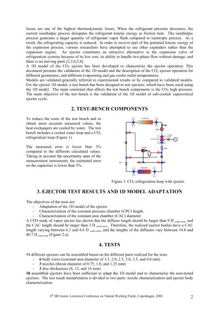
To reduce the costs <strong>of</strong> the test bench and to<br />
obtain more accurate measured values, the<br />
heat exchangers are <strong>cooled</strong> by water. The test<br />
bench includes a <strong>cooled</strong> water loop and a CO 2<br />
<strong>refrigeration</strong> loop (Figure 1).<br />
The measured error is lower than 3%<br />
compared to the different calculated values.<br />
Taking in account the uncertainty span <strong>of</strong> the<br />
measurement instruments, the estimated error<br />
on the capacities is lower than 5%.<br />
2. TEST-BENCH COMPONENTS<br />
Figure 1: CO 2 <strong>refrigeration</strong> loop with <strong>ejector</strong>.<br />
3. EJECTOR TEST RESULTS AND 1D MODEL ADAPTATION<br />
The objectives <strong>of</strong> the tests are:<br />
- Adaptation <strong>of</strong> the 1D model <strong>of</strong> the <strong>ejector</strong>.<br />
- Characterization <strong>of</strong> the constant pressure chamber (CPC) length.<br />
- Characterization <strong>of</strong> the constant area chamber (CAC) diameter.<br />
A CFD study <strong>of</strong> vapor <strong>ejector</strong> has shown that the diffuser length should be larger than 9 D const area , and<br />
the CAC length should be larger than 3 D const area . Therefore, the realized <strong>ejector</strong> bodies have a CAC<br />
length varying between 6.3 and 8.6 D const area , and the lengths <strong>of</strong> the diffusers vary between 10.8 and<br />
40.7 D const area (Figure 2.a).<br />
4. TESTS<br />
54 different <strong>ejector</strong>s can be assembled based on the different parts realized for the tests:<br />
- 6 body cores (constant area diameter <strong>of</strong> 1.5, 2.0, 2.5, 3.0, 3.5, and 4.0 mm)<br />
- 3 nozzles (throat diameter <strong>of</strong> 0.75, 1.0, and 1.25 mm)<br />
- 3 disc thicknesses (8, 12, and 16 mm).<br />
18 assembled <strong>ejector</strong>s have been sufficient to adapt the 1D model and to characterize the non-tested<br />
<strong>ejector</strong>s. The test result interpretation is divided in two parts: nozzle characterization and <strong>ejector</strong> body<br />
characterization.<br />
8 th IIR Gustav Lorentzen Conference on Natural Working Fluids, Copenhagen, 2008 2