
Create successful ePaper yourself
Turn your PDF publications into a flip-book with our unique Google optimized e-Paper software.
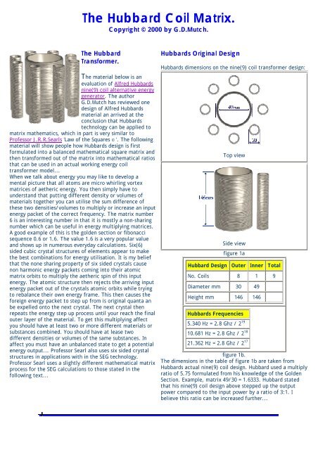
<strong>The</strong> <strong>Hubbard</strong> <strong>Coil</strong> <strong>Matrix</strong>.<br />
Copyright © 2000 by G.D.Mutch.<br />
<strong>The</strong> <strong>Hubbard</strong><br />
Transformer.<br />
<strong>The</strong> material below is an<br />
evaluation of Alfred <strong>Hubbard</strong>s<br />
nine(9) coil alternative energy<br />
generator. <strong>The</strong> author<br />
G.D.Mutch has reviewed one<br />
design of Alfred <strong>Hubbard</strong>s<br />
material an arrived at the<br />
conclusion that <strong>Hubbard</strong>s<br />
technology can be applied to<br />
matrix mathematics, which in part is very similar to<br />
Professor J.R.R.Searls 'Law of the Squares © '. <strong>The</strong> following<br />
material will show people how <strong>Hubbard</strong>s design is first<br />
formulated into a balanced mathematical square matrix and<br />
then transformed out of the matrix into mathematical ratios<br />
that can be used in an actual working energy coil<br />
transformer model...<br />
When we talk about energy you may like to develop a<br />
mental picture that all atoms are micro whirling vortex<br />
matrices of aetheric energy. You then simply have to<br />
understand that putting different density or volumes of<br />
materials together you can utilise the sum difference of<br />
these two densities/volumes to multiply or increase an input<br />
energy packet of the correct frequency. <strong>The</strong> matrix number<br />
6 is an interesting number in that it is mostly a non-sharing<br />
number which can be useful in energy multiplying matrices.<br />
A good example of this is the golden section or fibonacci<br />
sequence 0.6 or 1.6. <strong>The</strong> value 1.6 is a very popular value<br />
and shows up in numerous everyday calculations. Six(6)<br />
sided cubic crystal structures of elements appear to make<br />
the best combinations for energy utilisation. It is my belief<br />
that the none sharing property of six sided crystals cause<br />
non harmonic energy packets coming into their atomic<br />
matrix orbits to multiply the aetheric spin of this input<br />
energy. <strong>The</strong> atomic structure then rejects the arriving input<br />
energy packet out of the crystals atomic orbits while trying<br />
to rebalance their own energy frame. This then causes the<br />
foreign energy packet to step up from is original quanta an<br />
be expelled onto the next crystal. <strong>The</strong> next crystal then<br />
repeats the energy step up process until your reach the final<br />
outer layer of the material. To get this multiplying affect<br />
you should have at least two or more different materials or<br />
substances combined. You should have at lease two<br />
different densities or volumes of the same substances. In<br />
affect you must have an unbalanced state to get a potential<br />
energy output... Professor Searl also uses six sided crystal<br />
structures in applications with in the SEG technology.<br />
Professor Searl uses a slightly different mathematical matrix<br />
process for the SEG calculations to those stated in the<br />
following text...<br />
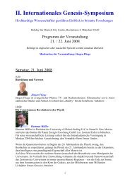
<strong>Hubbard</strong>s Original Design<br />
<strong>Hubbard</strong>s dimensions on the nine(9) coil transformer design:<br />
Top view<br />
Side view<br />
figure 1a<br />
<strong>Hubbard</strong> Design Outer Inner Total<br />
No. <strong>Coil</strong>s 8 1 9<br />
Diameter mm 30 49<br />
Height mm 146 146<br />
<strong>Hubbard</strong>s Frequencies<br />
5.340 Hz = 2.8 Ghz / 2 19<br />
10.681 Hz = 2.8 Ghz / 2 18<br />
21.362 Hz = 2.8 Ghz / 2 17<br />
figure 1b.<br />
<strong>The</strong> dimensions in the table of figure 1b are taken from<br />
<strong>Hubbard</strong>s actual nine(9) coil design. <strong>Hubbard</strong> used a multiply<br />
ratio of 5.75 formulated from his knowledge of the Golden<br />
Section. Example, matrix 49/30 = 1.6333. <strong>Hubbard</strong> stated<br />
that his nine(9) coil design above stepped up the output<br />
power compared to the input power by a ratio of 3:1. I<br />
believe this ratio can be increased further...
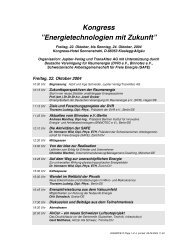
<strong>Matrix</strong> Formulation.<br />
<strong>The</strong> author will transform the values of <strong>Hubbard</strong>s nine(9)<br />
coil design of figure1 into a 3 x 3 balanced matrix. <strong>The</strong> 8<br />
<strong>Coil</strong>s around 1 inner coil equates to 9 coils which can be<br />
transformed into the 3 x 3 matrix below (see figure 2).<br />
63.25 30.0 53.75<br />
39.50 49.0 58.50<br />
44.25 68.0 34.75<br />
<strong>Matrix</strong> = 147<br />
Figure 2.<br />
<strong>Matrix</strong> Values Centre Outer * 3rd.<br />
No. <strong>Coil</strong>s 1 8 1<br />
Diameter mm 49 30 68<br />
Height mm 147 147 147<br />
2. Deriving <strong>Matrix</strong> <strong>Coil</strong> Turns = Volume :<br />
To derive the turns ratio you simply multiple the centre<br />
value 49 by multiples of 2. When you reach a value of<br />
Centre x 8 = 392 you will notice that the sum of the 8 outer<br />
cells around the centre value also equal the value 392. This<br />
is similar to Professor Searls Law of the Squares. See the<br />
table of figure 4.<br />
Centre [ 49] Turns<br />
Notes<br />
Centre x 4 196 <strong>Hubbard</strong>s original calculation<br />
Centre x 6 294 <strong>Hubbard</strong>s original calculation<br />
Centre x 8 392 * Alternative calculation<br />
Centre x 10 490 * Alternative calculation<br />
Centre x 12 588 <strong>Hubbard</strong>s original calculation<br />
Centre x 14 686 * Alternative calculation<br />
Centre x 16 784 * Alternative calculation<br />
figure 4<br />
(* Denotes alternative calculations that could be used in actual coil designs.)<br />
NB. Alfred <strong>Hubbard</strong> is obviously using binary in his<br />
calculations...<br />
* Hypothetical optional 3rd <strong>Coil</strong>.<br />
Figure 3.<br />
1. Derived values from the above matrix :<br />
<strong>The</strong> above matrix of figure 2 has a sum line value of 147. No<br />
matter which way you add the rows, columns or diagonals<br />
the line value will add to 147. <strong>The</strong> following values<br />
tabulated in random order are then derived from the<br />
balanced matrix . <strong>The</strong>se tabulated values are the actual<br />
physically wound coil dimensions from which you can build<br />
the <strong>Hubbard</strong> nine(9) coil energy transformer device.<br />
1. 1 x Centre <strong>Coil</strong> = 49mm Dia<br />
2. 8 x Outer <strong>Coil</strong>s = 30mm Dia.<br />
3. *1 x Hypothetical 3rd coil = 68mm Dia.<br />
4. Cylinder <strong>Coil</strong> length = 147mm<br />
5. <strong>Matrix</strong> Step value = 4.75<br />
6. Corners : Centre x 4 = 196<br />
7. 1st Ring : Centre x 8 = 392 (8 cells around the centre.)<br />
8. <strong>Matrix</strong> Frequency = 441hz<br />
{* This is a hypothetical coil added here by the author. See below text for more<br />
information.}<br />
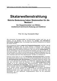
3. Deriving <strong>Matrix</strong> Copper Wire dimensions.<br />
To derive the copper wire gauge from the matrix you simply<br />
divide the turns (see figure 4) by the line value/cylinder length<br />
147mm. Example, 147/196 = 0.75 mm wire diameter.<br />
Knowing this last formula we can now construct a table with<br />
multiple choice coil dimensions for any derived wire size.<br />
(see figure 5)<br />
4. <strong>Matrix</strong> Final Physical <strong>Coil</strong> Dimensions :<br />
By using the matrix of figure 2 we have derived the optimal<br />
mathematical ratio values from which we can design the<br />
actual coil dimensions. Recapping, from the matrix we have<br />
derived :<br />
1. Cylinder Diameter<br />
2. Cylinder Length<br />
3. Turns Per <strong>Coil</strong>/Cylinder Ratio<br />
4. Wire Gauge/Diameter Ratio<br />
We may therefore tabulate all the values in the above steps<br />
into one easy to read table.(See figure 5) You may now use this<br />
table as a quick reference to build any coil for your chosen<br />
wire size.<br />
<strong>Coil</strong> Dimensions Table.<br />
Wire<br />
Gauge<br />
Turns/<br />
Cyl<br />
Lgth@<br />
30mm<br />
Lgth @<br />
49mm<br />
Lgth @<br />
*68mm<br />
0.186 788 74.26m 121.30m 168.33m<br />
0.214 686 64.65m 105.60m 146.54m<br />
0.25 588 55.41m 90.51m 125.61m<br />
0.3 490 46.18m 75.42m 104.67m<br />
0.375 392 36.94m 60.34m 83.74m<br />
Miscellaneous Errata :<br />
<strong>The</strong> below original <strong>Hubbard</strong> frequency information of figure<br />
6 is take from one design of the <strong>Hubbard</strong>s transformer<br />
device. <strong>The</strong> original reference image of <strong>Hubbard</strong>s<br />
transformer device was taken from Geoff Egels web site. I<br />
had once believed, and have now partly confirmed, that<br />
<strong>Hubbard</strong>s transformer device follows one of the<br />
aetheric/magnetic field matrices which are similar in part to<br />
that of J.R.R.Searls 'Law Of <strong>The</strong> Squares'. I believe the<br />
<strong>Hubbard</strong> coil/transformer device is tuned to the universal<br />
energy fields by utilising natural mathematical matrix law<br />
ratios.
0.5 294 27.70m 45.25m 62.80m<br />
0.75 196 18.47m 30.17m 41.87m<br />
figure 5<br />
* Denotes the optional 3rd coil dimension. As I am lead to<br />
believe, this third coil is not in <strong>Hubbard</strong>s original nine(9) coil<br />
design. <strong>The</strong> author has added this coil here to allow<br />
research into its possible further use as a power multiplying<br />
coil. It may be obvious to people that using a thicker wire<br />
diameter you will lose a corresponding number of turns per<br />
coil/cylinder. This then equates to a drop in voltage, but<br />
you should also gain with a corresponding current increase.<br />
Inversely, if you choose a thinner diameter wire gauge you<br />
will have a voltage increase for the corresponding drop in<br />
current. <strong>The</strong> trick would be to choose a wire diameter ratio<br />
for the frequency, current and voltage you wish to use.<br />
<strong>Hubbard</strong> stated he could use copper wire of different<br />
diameter/gauges to complete one totally wound coil. <strong>The</strong><br />
lengths shown in the above table equals the total copper<br />
wire length in meters that you will require to wind one<br />
complete coil onto the cylinder/former. <strong>The</strong> values do not<br />
include external connection flying leads.You will need extra<br />
wire for connection leads.<br />
To use the above table of figure 5 simply read down the<br />
vertical column of the desired wire diameter/gauge, then<br />
read across for the Turns and the Total Length of wire for<br />
each of the 30mm,49mm and 68mm diameter coils.<br />
Example, if you chose to use a wire gauge of 0.75mm you<br />
would use the following values :<br />
Simulating <strong>Hubbard</strong>s Math Calculations:<br />
Where and how does <strong>Hubbard</strong> derived most of his<br />
calculations? For example, his step value 5.75.? A suggestion<br />
is to use <strong>Hubbard</strong>s coil length 146 / 5.75 = 25.39. This value<br />
25.39 is very close to the value 25.4 which equals the<br />
imperial inch to metric value, or maybe binary 2 8 -2 = 254.<br />
Why did <strong>Hubbard</strong> choose the golden section as his start ratio<br />
? Could <strong>Hubbard</strong> have use this value 1.6 as his base unit of<br />
measure ? Other calculations deriving <strong>Hubbard</strong>s original<br />
math:<br />
49 / 30 = 1.6 (Golden section)<br />
1.61 / 0.28 = 5.75 (Step value)<br />
0.28 x 2 19 = 146,800.64 (<strong>Coil</strong> Length ?)<br />
146.9 /49 = 2.997959184 ( C in physics )<br />
146/5.75 = 25.4 (Imperial inch conversion)<br />
0.28 / 2 19 = 0.000000534 (<strong>Hubbard</strong>s freq.)<br />
0.28 / 2 18 = 0.00000010681 (<strong>Hubbard</strong>s freq.)<br />
0.28 / 2 17 = 0.00000021362 (<strong>Hubbard</strong>s freq.)<br />
Reversing <strong>Hubbard</strong>s calculations we can derive a more<br />
accurate value for <strong>Hubbard</strong>s Natural Frequency : 2 19 x 5.340<br />
= 2799697.92 Hz. <strong>The</strong> following are <strong>Hubbard</strong>s original values<br />
along with the authors modified values in the table of figure<br />
6.<br />
<strong>Hubbard</strong>s Original Freq.<br />
2.8<br />
<strong>Hubbard</strong>s Modified Freq.<br />
2.799<br />
5.340 = 2.8 Ghz / 2 19 2799697.92 / 2 19 =<br />
5.34 Hz<br />
10.681= 2.8 Ghz / 2 18 2799697.92 / 2 18 =<br />
10.68 Hz<br />
21.362 = 2.8 Ghz / 2 17 2799697.92 / 2 17 =<br />
21.36 Hz<br />
figure 6<br />
Wire Gauge 0.75mm<br />
Turns : 196<br />
30mm Dia 18.472 m<br />
49mm Dia 30.171 m<br />
68mm Dia<br />
41.871 m<br />
( Optional 3rd coil. )<br />
<strong>The</strong> values listed above represent one totally wound coil per<br />
cylinder. <strong>Hubbard</strong> used 8 coils on the outer peripheral of the<br />
inner coil, so you will need to multiply the 30mm dia values<br />
by 8 to get the total resource material required.<br />
END.<br />
<strong>Hubbard</strong> used a coil/cylinder height of 146mm. <strong>The</strong> true<br />
coil/cylinder length ratio according to <strong>Hubbard</strong>s text, should<br />
have been his own given ratio 5.75 x 25.4 = 146.05mm. <strong>The</strong><br />
true line value of 147 mapped from with in the matrix of<br />
figure 2 is not the same as <strong>Hubbard</strong>s value 146.05, which is<br />
missing 0.95mm. If you take small liberties an assume<br />
<strong>Hubbard</strong>s own calculations of 1.44Ghz ( 1/ 0.694444 similar<br />
to Bruce Cathies reciprocal harmonic speed of light) as a<br />
base ratio; the step value becomes 2.88 ( <strong>Hubbard</strong>s<br />
frequency )Ghz /2 = 1.44 Ghz x 3.141592654(pi) =<br />
4.523893421. If you use this 4.52 value as <strong>Hubbard</strong>s step<br />
ratio in a new matrix, then the completed matrix line and<br />
coil length value becomes 146.97mm. This value is then 0.03<br />
In my opinion I believe <strong>Hubbard</strong> could have placed another<br />
coil over the inner most coil an produced more output power<br />
yet again. <strong>Hubbard</strong> stated that power output of his nine(9)<br />
coil design was 3:1 i.e. 3 times the output as per the input.<br />
I believe if <strong>Hubbard</strong> used a 3rd coil design as in the matrix<br />
above, then the output could step up to 14 :1. <strong>The</strong> optional<br />
3rd coil could be the 68mm diameter coil from the matrix.<br />
Was/is the original coil and cylinder in the original plan<br />
design? I am unable to determine if this is the case as I have<br />
only perused one portion of <strong>Hubbard</strong>s original designs.<br />
<strong>The</strong> above miscellaneous errata is just an evaluation of
different to the authors 147mm matrix line value of figure 2.<br />
By transposing the matrix step value of figure 2 as <strong>Hubbard</strong>s<br />
step value an original frequency values in figure 6, I am able<br />
to reverse engineer and derive a value of 4.75 / pi = 1.51 x 2<br />
= 3.02 Ghz. What could this value represent ? I wonder why<br />
<strong>Hubbard</strong> chose binary harmonic values ? Is <strong>Hubbard</strong> using the<br />
values from the table of figure 6 as input an output<br />
frequencies ? Example, should you input 2 19 = 524288 Hz and<br />
the output = 5.340Hz ? Could a lanthanide element series or<br />
a radioactive isotope be used as a cylinder former for an<br />
input constant pulse frequency, and thus producing an over<br />
unity constant output by not having to input an EMF into the<br />
primary coil(s) ?<br />
Again using similar math techniques as <strong>Hubbard</strong> I can<br />
simulate his frequency values together with my own values<br />
from the matrix of figure 2, and derive the below theoretical<br />
comparison table of figure 6. <strong>The</strong> following table will show<br />
the reader how the author derived a constant frequency<br />
from a binary ratio and the matrix line value or coil length in<br />
this case.<br />
<strong>Matrix</strong> Values Alternative <strong>Hubbard</strong> Values<br />
147 (line value ) / 2 19 =<br />
0.00028038<br />
146 (line value ) / 2 19 =<br />
0.000278472<br />
2803800 / 2 19 = 5.34782 Hz 2784720 / 2 19 = 5.3114<br />
2803800 / 2 18 = 10.6956 Hz 2784720 / 2 18 = 10.622<br />
2803800 / 2 17 = 21.3912 Hz 2784720 / 2 17 = 21.215<br />
<strong>Hubbard</strong>s math methods which the author has used to<br />
simulate possible comparisons against the natural method of<br />
a matrix. A couple of different slants on the same math<br />
methods have been added above for the reader to compare<br />
and research. I feel the reader should first research with<br />
<strong>Hubbard</strong>s own successful coil/transformer calculations and<br />
design before moving on to the information presented here<br />
in. <strong>The</strong> author presents the above matrix information as a<br />
further refinement to <strong>Hubbard</strong>s own methods, to support<br />
<strong>Hubbard</strong>s claim to a successful alternative energy device.<br />
More importantly : don't let ego and greed cloud your better<br />
judgement. Please share all your research findings with<br />
others. Let's all make a conscious decision to create a<br />
cleaner, freer living world for all...<br />
Acknowledgments:<br />
<strong>The</strong> <strong>Hubbard</strong> <strong>Matrix</strong> Math is Copyright © 2000, by G.D.Mutch<br />
<strong>The</strong> original <strong>Hubbard</strong> transformer design is Copyright©<br />
property of Alfred <strong>Hubbard</strong> 1929...<br />
Geoff Egels Natural Energy Web Site : www.energy21.org<br />
'Law Of <strong>The</strong> Squares Books' are Copyright of Prof.<br />
J.R.R.Searl.<br />
Bruce Cathie Book Series: Harmonic Universe<br />
figure 7<br />
Natural <strong>Matrix</strong> Frequency = 441 Hz<br />
441 Hz = 2.8901376(nearest) Ghz / 2 16 (Derived using<br />
<strong>Hubbard</strong>s method)<br />
http://www.atl2.netfirms.com/engy/mutch/matrixlaw/hubbard.htm