AIR CONDITIONING - Rafstjorn
AIR CONDITIONING - Rafstjorn
AIR CONDITIONING - Rafstjorn

Create successful ePaper yourself
Turn your PDF publications into a flip-book with our unique Google optimized e-Paper software.
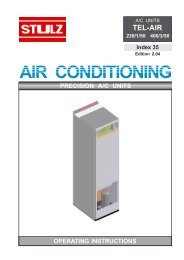
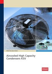
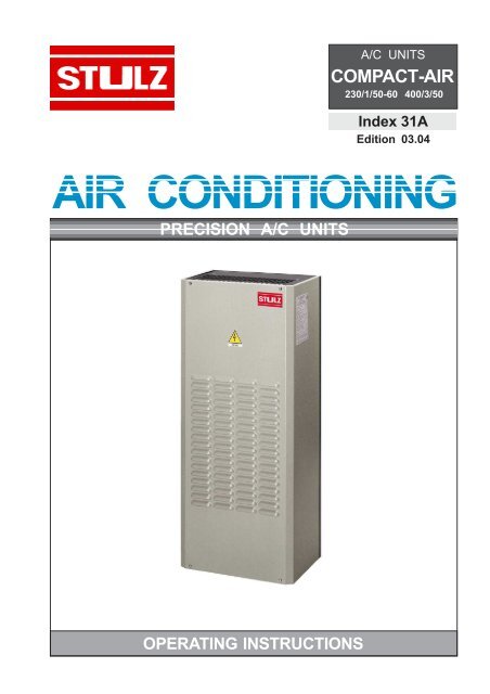
A/C UNITS<br />
COMPACT-<strong>AIR</strong><br />
230/1/50-60 400/3/50<br />
Index 31A<br />
Edition 03.04<br />
<strong>AIR</strong> <strong>CONDITIONING</strong><br />
PRECISION A/C UNITS<br />
OPERATING INSTRUCTIONS
E/0304/31A/2
Contents<br />
Page<br />
Introduction 4<br />
Technical Data 6<br />
Capacity Diagrams 8<br />
Dimensions 13<br />
1. Unpacking and Inspection 14<br />
2. Unit Identificaton 15<br />
3. Operating Principle 16<br />
4. Precautions 18<br />
5. Safety Considerations 18<br />
6. Precautions when handling the Unit 19<br />
7. Installation 19<br />
8. Vibrations 24<br />
9. Mechanical Parts 24<br />
10. Cooling Components 24<br />
11. Motors 25<br />
12. Control, Monitoring and Safety Components 26<br />
13. Electrical Connections 28<br />
14. Start-up 29<br />
15. Adjusting the Temperature 29<br />
16. First Checks after starting the Unit 30<br />
17. Switching off 30<br />
18. Maintenance 30<br />
19. Inactivity 31<br />
20. Options 32<br />
21. Residual Hazards and Emergency Information 34<br />
22. Disassembling the Unit 38<br />
23. Faults, probable Causes, possible Remedies 39<br />
The manufacturer reserves the right to make alterations without notice.<br />
E/0304/31A/3
Introduction<br />
The following information is supplied in accordance with Standards:CE73/23,CE93/<br />
68,CE89/392:<br />
MANUFACTURER'S NAME AND ADDRESS<br />
STULZ GmbH<br />
Holsteiner Chaussee 283<br />
22480 Hamburg<br />
DATA REGARDING THIS MODEL<br />
Air conditioner for telecom application<br />
YEAR OF MANUFACTURE<br />
As shown on the technical name plate on the unit<br />
HOW TO CONSULT THIS MANUAL<br />
This document contains general informations valid for all models of the series. Further<br />
informations like wiring diagrams etc. will be delivered with each unit.<br />
THIS MANUAL IS INTENDED FOR<br />
OWNER OF THE APPLIANCE<br />
PERSON RESPONSIBLE FOR ITS INSTALLATION<br />
PERSON RESPONSIBLE FOR MANAGING THE PRODUCT<br />
PERSON RESPONSIBLE FOR ORDINARY MAINTENANCE<br />
PERSON RESPONSIBLE FOR ITS DISASSEMBLY<br />
PURPOSE OF THE INFORMATION CONTAINED IN THIS MANUAL:<br />
CORRECT HANDLING<br />
performed by unskilled personnel<br />
CORRECT INSTALLATION<br />
performed by skilled personnel;<br />
CORRECT START-UP<br />
performed by personnel trained by STULZ;<br />
CORRECT MANAGEMENT<br />
performed by skilled personnel;<br />
CORRECT MAINTENANCE<br />
performed by skilled personnel;<br />
CORRECT ORDER FOR SPARE PARTS, made by skilled personnel;<br />
CORRECT DISPOSAL OF THE PRODUCT, made by skilled personnel.<br />
RESTRICTIONS TO THE USE OF THIS MANUAL<br />
They apply to any operations that must be performed by highly skilled personnel.<br />
E/0304/31A/4
WHERE AND HOW TO STORE THIS MANUAL<br />
Inside the electric cabinet or together with any other literature concerning the equipment<br />
which utilizes the product, provided it is a dry and clean place.<br />
In the event of the manual being misplaced or damaged, the customer may require, for a<br />
fee, a new manual, by quoting the model and serial number shown on the technical<br />
name- plate, by contacting your local STULZ partner.<br />
CURRENT TECHNOLOGY<br />
This manual reflects the state of the art existing at the time the product is marketed and<br />
shall not be deemed to be inadequate for the sole reason that it has not been updated as<br />
a result of any new experience.<br />
UPDATES<br />
STULZ reserves the right to update the product and relevant manual without being<br />
required to update previous products and manuals other than in exceptional<br />
circumstances. To require or receive any updates of the instructions manual or<br />
amendments thereto, which shall be deemed to be an integral part of the manual, please<br />
contact your local STULZ partner.<br />
FOR FURTHER INFORMATION<br />
Please contact your local STULZ partner.<br />
Any suggestions or recommendations made by installers or users of the product for the<br />
purpose of improving the product or the contents of this manual, will be greatly<br />
appreciated by the Manufacturer.<br />
IN THE EVENT OF SALE OF THE PRODUCT<br />
Please advise STULZ GmbH of the address of the new owner so as to enable the<br />
dispatch of any updates to the manual, otherwise STULZ GmbH shall be relieved of any<br />
subsequent liabilities<br />
E/0304/31A/5
Technical Data CVC 07 002yy - CVC 20 002yy (at 50 Hz)<br />
CVC 07 0 02yy<br />
CVC 14 0 02yy<br />
CVC 20 0 02yy<br />
Cooling capacity L35L35 - (DIN3168)<br />
Cooling capacity L35L50 - (DIN3168)<br />
Refrigerant<br />
W<br />
W<br />
750<br />
580<br />
R134a<br />
1400<br />
1170<br />
R134a<br />
2000<br />
1700<br />
R134a<br />
Condenser fan<br />
Number/Type<br />
Air flow<br />
m³/h<br />
1/Ø190 radial<br />
400<br />
1/Ø220 radial<br />
650<br />
1/Ø225 radial<br />
850<br />
Evaporator fan<br />
Number/Type<br />
Air flow<br />
m³/h<br />
1/Ø150 compact<br />
(axial)<br />
220<br />
1/Ø190 radial<br />
390<br />
1/Ø190 radial<br />
390<br />
Refrigerant charge<br />
External operating limit temp. min/max<br />
Cabinet operating limit temp. min/max<br />
Extern noise level **<br />
Internal noise level ***<br />
Duty cycle<br />
Weight<br />
Height / Width / Depth<br />
kg<br />
°C<br />
°C<br />
dB(A)<br />
dB(A)<br />
%<br />
kg<br />
mm<br />
0.35<br />
-20/+55*<br />
+25/+45<br />
62<br />
52<br />
100<br />
25<br />
634/308/227<br />
0.55<br />
-20/+55*<br />
+25/+45<br />
73<br />
62<br />
100<br />
42<br />
1004/417/251<br />
0.65<br />
-20/+55*<br />
+25/+45<br />
71<br />
62<br />
100<br />
44<br />
1004/417/251<br />
Electrical Data<br />
Power Supply Code<br />
Nominal voltage<br />
Tolerance on voltage<br />
Phase<br />
Nominal frequency<br />
Tolerance on frequency<br />
Power consumption L35L50<br />
Locked rotor current (LRA)<br />
Operating current (OA)<br />
V<br />
ph<br />
Hz<br />
W<br />
A<br />
A<br />
20<br />
230<br />
±10%<br />
1<br />
50-60<br />
± 2%<br />
400<br />
16<br />
2.3<br />
20<br />
230<br />
±10%<br />
1<br />
50-60<br />
± 2%<br />
850<br />
17<br />
4.1<br />
20<br />
230<br />
±10%<br />
1<br />
50-60<br />
± 2%<br />
1190<br />
20<br />
6.1<br />
Condenser Fan<br />
Power consumption<br />
Operating current<br />
W<br />
A<br />
61<br />
0.27<br />
90<br />
0.4<br />
165<br />
0.73<br />
Evaporator Fan<br />
Power consumption<br />
Operating current<br />
W<br />
A<br />
29<br />
0.15<br />
61<br />
0.27<br />
61<br />
0.27<br />
* 50°C at 60 Hz<br />
** measured at 2m distance from the unit front side (condenser side), free-field, external temp. higher than 40°C<br />
*** measured at 2m distance from the unit back side (evaporator side), free-field, external temp. higher than 40°C<br />
E/0304/31A/6
Technical Data CVC 28 002yy - CVC 41 002yy (at 50 Hz)<br />
CVC 28 0 02yy<br />
CVC 41 0 02yy<br />
Cooling capacity L35L35 - (DIN3168)<br />
Cooling capacity L35L50 - (DIN3168)<br />
Refrigerant<br />
W<br />
W<br />
2700<br />
2300<br />
R134a<br />
3900<br />
2900<br />
R134a<br />
Condenser fan<br />
Number/Type<br />
Air flow<br />
m³/h<br />
1/Ø250 radial<br />
1150<br />
1/Ø250 radial<br />
1150<br />
Evaporator fan<br />
Number/Type<br />
Air flow<br />
m³/h<br />
1/Ø220 radial<br />
650<br />
1/Ø250 radial<br />
1150<br />
Refrigerant charge<br />
External operating limit temp. min/max<br />
Cabinet operating limit temp. min/max<br />
Extern noise level **<br />
Internal noise level ***<br />
Duty cycle<br />
Weight<br />
Height / Width / Depth<br />
kg<br />
°C<br />
°C<br />
dB(A)<br />
dB(A)<br />
%<br />
kg<br />
mm<br />
1<br />
-20/+50<br />
+25/+45<br />
75<br />
73<br />
100<br />
81<br />
1234/509/382<br />
1.05<br />
-20/+50<br />
+25/+45<br />
75<br />
75<br />
100<br />
86<br />
1234/509/382<br />
Electrical Data<br />
Power Supply Code<br />
Nominal voltage<br />
Tolerance on voltage<br />
Phase<br />
Nominal frequency<br />
Tolerance on frequency<br />
Power consumption L35L50<br />
Locked rotor current (LRA)<br />
Operating current (OA)<br />
V<br />
ph<br />
Hz<br />
W<br />
A<br />
A<br />
20<br />
230<br />
±10%<br />
1<br />
50-60<br />
±2%<br />
1450<br />
35<br />
7.5<br />
42<br />
400<br />
±10%<br />
3+N<br />
50<br />
±2%<br />
1450<br />
16<br />
3<br />
20<br />
230<br />
±10%<br />
1<br />
50-60<br />
±2%<br />
1770<br />
46.5<br />
8.3<br />
42<br />
400<br />
±10%<br />
3+N<br />
50<br />
±2%<br />
1770<br />
18<br />
3.5<br />
Condenser Fan<br />
Power consumption<br />
Operating current<br />
W<br />
A<br />
152<br />
0.69<br />
152<br />
0.69<br />
152<br />
0.69<br />
152<br />
0.69<br />
Evaporator Fan<br />
Power consumption<br />
Operating current<br />
W<br />
A<br />
90<br />
0.4<br />
90<br />
0.4<br />
152<br />
0.69<br />
152<br />
0.69<br />
* 50°C at 60 Hz<br />
** measured at 2m distance from the unit front side (condenser side), free-field, external temp. higher than 40°C<br />
*** measured at 2m distance from the unit back side (evaporator side), free-field, external temp. higher than 40°C<br />
E/0304/31A/7
Capacity diagram CVC 07 002 yy (at 50 Hz)<br />
Cooling capacity [W]<br />
Inside<br />
temp.<br />
[°C]<br />
Outside temperature [°C]<br />
E/0304/31A/8
Capacity diagram CVC 14 002 yy (at 50 Hz)<br />
Cooling capacity [W]<br />
Inside<br />
temperature<br />
[°C]<br />
Outside temperature [°C]<br />
E/0304/31A/9
Capacity diagram CVC 20 002 yy (at 50 Hz)<br />
Cooling capacity [W]<br />
Inside<br />
temp.<br />
[°C]<br />
Outside temperature [°C]<br />
E/0304/31A/10
Capacity diagram CVC 28 002 yy (at 50 Hz)<br />
Cooling capacity [W]<br />
Inside<br />
temperature<br />
[°C]<br />
Outside temperature [°C]<br />
E/0304/31A/11
Capacity diagram CVC 41 002 yy (at 50 Hz)<br />
Cooling capacity [W]<br />
Inside<br />
temp.<br />
[°C]<br />
Outside temperature [°C]<br />
E/0304/31A/12
Dimensions<br />
B<br />
C<br />
A<br />
Type<br />
CVC 07<br />
CVC 14-20<br />
CVC 28-41<br />
A<br />
634<br />
1004<br />
1234<br />
B<br />
308<br />
417<br />
509<br />
C<br />
227<br />
251<br />
382<br />
E/0304/31A/13
1. Unpacking and Inspection<br />
STULZ products are shipped ex-works. All units have been individually inspected in all<br />
their parts and carefully packaged.<br />
Immediately inspect the unit upon receipt, making sure it has been shipped in its proper<br />
position. Note improper shipment on the shipping document.<br />
We recommend you accepting merchandise subject to inspection.<br />
UP<br />
UP<br />
UP<br />
Check for damage and, if any, note this immediately on the shipping document. Remove<br />
packing and check that the exterior casing is not scratched, marked or have signs of blows<br />
and that no components are missing and that there are no traces of oil. Before throwing the<br />
packaging away check that it does not contain documents or parts of the machine.<br />
Any damage that is encountered must be notified to the carrier by registered letter within 8<br />
days of receipt. The carrier is responsible for any damage caused during shipment. STULZ<br />
is not responsible for damage caused to the merchandise by the shipper but will do all in<br />
its power to assist customers in these situations.<br />
N.B. This product may not be returned without prior written approval by STULZ.<br />
For any assistance please contact your local STULZ partner.<br />
NOTE: If installation of the product is not required immediately or the product needs<br />
to be onforwarded to its final destination, replace it in its packing, after inspecting it,<br />
and store it in a safe place.<br />
WARNING! As an environmental concern, we recommend to recycle the<br />
packing cartons and to separate them from any plastic.<br />
E/0304/31A/14
2. Unit Identification<br />
This unit can be correctly identified by the<br />
technical name-plate containing all the<br />
information for its correct use.<br />
In addition to the manufacturer's identification<br />
data and the product trade-marks, the nameplate<br />
contains the following information:<br />
The technical name-plate is embossed on a<br />
plastic support which ensures high endurance<br />
of the text even in particularly difficult<br />
environments.<br />
N.B. For any assistance or information<br />
concerning the unit described in this manual,<br />
knowledge of its serial number is essential.<br />
Constructor<br />
Model<br />
Series<br />
Date<br />
Nominal voltage<br />
Control voltage<br />
Phase<br />
Frequency<br />
Trademark<br />
This identifies the product family.<br />
Product identification number.<br />
Date on which the product is placed<br />
on the market and date of<br />
commencement of warranty.<br />
Voltage to be supplied to the unit<br />
Working voltage of the auxiliary<br />
circuits if different from the voltage<br />
rating.<br />
Voltage phase<br />
Voltage frequency.<br />
Start/Run current<br />
Current absorbed when starting the compressor. /<br />
Current absorbed during operation at the permitted<br />
maximum temperature<br />
Cooling capacity<br />
Unit cooling capacity with 35°C inside cabinet<br />
temperature and 35°C ambient temperature conditions.<br />
Power absorbed<br />
Power absorbed by the unit with 35°C inside cabinet<br />
temperature and 50°C ambient temperature conditions.<br />
Automatic circuit breaker curve type C, Safety<br />
fuse type aM<br />
Rating of the automatic switch/safety fuse to be installed<br />
by the installer.<br />
Inside temperature<br />
Minimum and maximum cabinet temperature where the<br />
machine works and for which the machine was<br />
designed.<br />
Outside temperature<br />
Minimum and maximum ambient temperature where<br />
the machine works and for which the machine was<br />
designed<br />
Refrigerant charge<br />
Quantity of refrigerant contained in the unit's<br />
refrigeration circuit<br />
Type of refrigerant<br />
Brand name of the refrigerant used in the unit's cooling<br />
circuit<br />
Maximum pressure<br />
Maximum pressure at which the refrigeration circuit<br />
functions<br />
Cabinet side protection IP<br />
protection level in the direction of the cabinet<br />
Ambient side protection IP<br />
protection level in the direction of the ambient<br />
Weight Empty weight of the machine<br />
Duty Cycle Operational capacity of the unit<br />
E/0304/31A/15
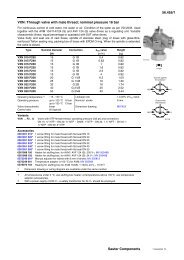
3. Operating Principle<br />
STULZ conditioners are designed to cool electric cabinets with IP54 protection level and<br />
they are suitable for the operation in industrial environments. Their use allows to eliminate<br />
problems caused by high temperatures, dirt and humidity which are present in the<br />
environment.<br />
The unit, which is basically made up of a sealed cooling circuit where the refrigerant<br />
circulates, is divided into two sections, hermetically separated from each other, where the<br />
air in the environment and the air in the cabinet are treated without coming into contact<br />
with each other.<br />
The system operates as follows:<br />
The compressor compresses the refrigerant gas bringing it to a high pressure and<br />
temperature.<br />
The hot gas, by going through the condenser, is cooled and liquefied thus releasing heat<br />
to the air in the environment. Pushed through the capillary pipe, the liquid refrigerant loses<br />
pressure, which makes it prone to evaporation. This takes place in the evaporator, where<br />
the refrigerant absorbs the heat of the warm air from the cabinet, which is therefore cooled.<br />
Condenser pressure<br />
switch (proportional control)<br />
Filter dryer<br />
Capillary pipe<br />
Condenser fan<br />
Evaporator fan<br />
Evaporator<br />
Condenser<br />
HP switch<br />
LP switch<br />
Compressor<br />
Regulating<br />
thermostat<br />
E/0304/31A/16
Air flow inside the unit<br />
Outdoor application<br />
INTERNAL SIDE<br />
EXTERNAL SIDE<br />
Condenser<br />
Evaporator fan<br />
Condenser fan<br />
Evaporator<br />
Compressor<br />
E/0304/31A/17
4. Precautions<br />
The CVC series cooling units are designed to operate as a wall-type unit and in an upright<br />
position. For all models the compressor is and must always be in an upright position.The<br />
cooling units may not be used or transported in a position other than that for which they<br />
have been designed.<br />
WARNING!<br />
Never run the machine if you have discovered leakage of the coolant fluid.<br />
If traces of oil are present on the unit, which point to a loss of coolant, on the inside or the<br />
outside, then the equipment must be thoroughly checked before starting the unit and, if<br />
necessary, the technical department of your local STULZ partner should be contacted.<br />
5. Safety Considerations<br />
The installation and handling of cooling units may be hazardous as they form a pressurised<br />
system with electric components.<br />
Only skilled personnel may repair, inspect or maintain the cooling units.<br />
All other operations must be performed by personnel who are experienced and qualified in<br />
the maintenance of cooling systems.<br />
Before servicing this unit, refer to the instructions contained in this manual, check the data<br />
on the data plate and follow any other precaution to ensure optimum safety.<br />
WARNING!<br />
Never work on the unit without having disconnected the power supply<br />
before!<br />
E/0304/31A/18
6. Precautions when handling the Unit<br />
To move this unit, when it is still packaged, use<br />
a fork lift or a system using cables or chains.<br />
When the packing is removed, use two M6<br />
eyebolts, attaching them to the upper part of the<br />
cooling unit, where appropriate holes have<br />
already been arranged.<br />
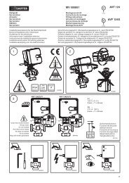
7. Installation<br />
1 Unpack the unit taking care not to damage its exposed parts. Before discarding it,<br />
check the packaging for any parts or documents. Check that the supply voltage is as<br />
designated.<br />
2 Check that:<br />
- there is space enough for an easy application and installation, both inside and<br />
outside the cabinet;<br />
- the cabinet is at least of the IP54 type;<br />
- the cabinet is clean on the inside;<br />
- the cabinet is not in the proximity of heat sources or warm air flows;<br />
- the inside of the cabinet allows a proper air circulation, preventing any recirculation.<br />
It is important to prevent hot air expelled by the condenser fan from being even partially<br />
sucked back in. This would cause continuous stoppages, commanded by the pressure<br />
switches, reducing efficiency and increasing electricity consumption. Improper operation<br />
of this type can quickly cause irreparable harm to the compressor.<br />
WARNING!<br />
Do not obstruct circulation by air being sucked into or expelled from the air<br />
conditioner.<br />
E/0304/31A/19
3 The cooling unit must be installed as high as possible;<br />
4 If installed on a door, make sure the hinges can withstand the weight of the unit;<br />
5 make sure the electric cable is not torn or damaged when the door is closed;<br />
6 If the depth of the cooling unit prevents the door from being completely opened, arrange<br />
a stopper for such a door.<br />
7 Prior to servicing the cabinet, disconnect power supply to the same.<br />
Prior to drilling holes or making cuts on the cabinet, make sure that holes, screws,<br />
cables, etc. do not interfere with the equipment which has already been installed. Make<br />
cuts on the cabinet panels by following the relevant template.<br />
8 Once the anchoring holes have been drilled in the cabinet wall, mount the eyebolts to<br />
handle the unit. the necessary cut-outs corresponding to the unit size can be seen on<br />
the following pages.<br />
9 Glue the adhesive gasket around the edges of the holes drilled on the cabinet;<br />
10 Position the cooling unit at the cabinet and secure it with the appropriate screws.<br />
adhesive gasket<br />
threaded inserts<br />
NOTE:<br />
Compact-Air units are already provided with<br />
threaded inserts, in correspondance with the<br />
fixing holes at the cut-out.<br />
Therefore the fixing holes at the cabinet wall<br />
must not be provided with threaded inserts.<br />
threaded inserts<br />
Failure to comply with these requirements, in addition to affecting proper unit<br />
operation, invalidates warranty coverage.<br />
E/0304/31A/20
Cut-outs for CVC 07 002yy<br />
308<br />
68<br />
172<br />
68<br />
590<br />
92<br />
634<br />
95<br />
150<br />
27<br />
12<br />
261<br />
4 x Ø8<br />
2 x Ø22<br />
42 45<br />
17<br />
24<br />
260<br />
24<br />
E/0304/31A/21
Cut-outs for CVC 14 002yy - CVC 20 002yy<br />
108.5<br />
200 108.5<br />
108,5 200<br />
108,5<br />
38,5 38.5<br />
340<br />
38,5<br />
38.5<br />
340<br />
340 22<br />
150 200<br />
40<br />
N° 2 Holes Ø 22<br />
118,5<br />
118.5<br />
202 720<br />
82<br />
1004<br />
172<br />
28.5<br />
360<br />
28,5 360<br />
28.5<br />
28,5<br />
417<br />
417<br />
E/0304/31A/22
Cut-outs for CVC 28 002yy - CVC 41 002yy<br />
215<br />
198 95<br />
39<br />
430 39<br />
1234<br />
6 x Ø8<br />
530<br />
240<br />
390<br />
400<br />
215<br />
201<br />
40<br />
113<br />
36<br />
Ø35<br />
Ø22<br />
103<br />
59<br />
390<br />
508<br />
59<br />
E/0304/31A/23
8. Vibrations<br />
The cooling unit does not produce any significant vibrations as the parts which generate<br />
them are installed on anti-vibration devices.<br />
9. Mechanical Parts<br />
9.1 STRUCTURE<br />
These machines are composed using self-supporting panels. These are made of passivated<br />
and baked enamel sheet metal to guarantee resistance against corrosion*. They make the<br />
machine easy to inspect and, at the same time, offer adequate protection to its internal<br />
components.<br />
Internal components of the structure are only accessible by removing cladding panels.<br />
These are removed by extracting their fastening screws using suitable tools.<br />
*suitable only to non-corrosive and non-salty environment<br />
10. Cooling Components<br />
These are connected together by copper piping, appropriately welded to ensure a good<br />
seal.<br />
10.1 REFRIGERANT<br />
The refrigerant that is used: R134a (Tetrafluorethane).<br />
It is neither toxic nor flammable and is not harmful to the ozone layer (ODP = 0).<br />
10.2 COMPRESSOR<br />
In this unit a reciprocating hermetic compressor is used.<br />
Compressors are basically composed of an electric motor and a mechanical section which<br />
is powered by this motor for pumping the refrigerant gas.<br />
In reciprocating compressors the pumping unit consists of a piston which slides inside a<br />
cylinder and which generates, depending on its phase, compression and aspiration.<br />
10.3 CONDENSER<br />
This part allows the release of the heat of the refrigerant gas in the environment. It consists<br />
of an exchange pack with copper piping and aluminium fins.<br />
(suitable only to non-corrosive and non-salty environment)<br />
10.4 FILTER DRYER<br />
This is a mixed mechanical/chemical filter and serves the purpose of filtering the refrigerant<br />
which goes through it, at the same time eliminating humidity particles.<br />
E/0304/31A/24
10.5 CAPILLARY PIPE EXPANSION SYSTEM<br />
This part causes a pressure drop of the refrigerant before it comes into the evaporator.<br />
10.6 EVAPORATOR<br />
This is the part where the transfer of the heat, contained in the air in the cabinet, to the<br />
refrigerant gas takes place .<br />
It consists of copper pipes and aluminium fins.<br />
(suitable only to non-corrosive and non-salty environment)<br />
11. Motors<br />
11.1 COMPRESSOR<br />
Electric motor with a squirrel cage rotor, positioned inside the compressor and cooled by<br />
the air flow. It is mounted on anti-vibration springs to reduce vibrations.<br />
11.2 FANS<br />
These may be of different types depending on the model. They are either:<br />
- multiblade axial, with outside rotor on bearings, dynamically balanced;<br />
- compact axial, on bearings;<br />
- radial, with plastic or metal rotor, on bearings;<br />
These fans are manufactured in accordance with Standard EN 60 335 1. They are treated<br />
with anticorrosion plastic materials, with class B insulation and class 1 protection.<br />
The motor protection is IP44, in accordance with Standard DIN40500 whereas the safety<br />
rate complies with Standards DIN30110.<br />
Noise levels are consistent with Standard DIN 45635.<br />
E/0304/31A/25
12. Control, Monitoring and Safety Components<br />
All equipment is set and inspected at the factory and generally does not require further<br />
adjustments or interventions.<br />
If, for specific reasons, it becomes necessary to perform modifications on the settings of<br />
automatic devices this task must only be performed, subsequent to notification to the STULZ<br />
engineering service, by specialized product expert.<br />
STULZ air conditioner are equipped with a set of devices designed to ensure proper<br />
operation. Intervention by any one of these automatic safety devices is a sign of a malfunction<br />
and it is absolutely necessary to eliminate the cause of the malfunction.<br />
WARNING!<br />
It is prohibited to make electrical by-passes on safety equipment.<br />
This intervention, in addition to being dangerous, also immediately invalidates<br />
guarantee coverage for the product.<br />
Interrupt electrical power to the unit before performing any repair or maintenance.<br />
Work on the unit must only be done by expert, qualified and authorized personnel.<br />
12.1 HIGH PRESSURE SAFETY SWITCH<br />
stops compressor operation when the pressure inside the refrigeration circuit exceeds the<br />
design values.<br />
12.2 LOW PRESSURE SAFETY SWITCH<br />
stops compressor operation when the pressure inside the refrigeration circuit drops below<br />
the design values.<br />
12.3 CONDENSATION CONTROL PRESSURE SWITCH<br />
(fan speed control )<br />
It controls the condenser fan speed to keep the condensing temperature constant.<br />
Changes of fan speed are obtained by changing the supply voltage depending on the<br />
condenser temperature.<br />
12.4 CONTACTORS<br />
control the motors by operating with auxiliary voltage.<br />
They refer to IEC947-4-1 standards.<br />
12.5 TRANSFORMER<br />
refers to EN60742 standard and transforms the supply voltage to the auxiliary control voltage<br />
E/0304/31A/26
12.6 REGULATING THERMOSTAT<br />
The mechanical thermostat with a gas charge is positionned at the air intake of the cabinet<br />
and it measures and controls the temperature to provide the start signal for the compressor.<br />
It can be adjusted within the allowed temperature range of the technical data sheet.<br />
12.7 HEATING ELEMENT THERMOSTAT (supplied with the reheat option, only for CVC14/<br />
20/28/41)<br />
The mechanical thermostat with a gas charge is positionned at the air intake of the cabinet<br />
and it measures and controls the temperature to provide the start signal for the heating<br />
element.<br />
E/0304/31A/27
13. Electrical Connections<br />
WARNING!<br />
It is absolutely necessary, before making any connections, to use a suitable tester<br />
to check the supply voltage. This must be the same as the voltage indicated on<br />
the technical data plate.<br />
The user must furnish and install, upstream from the unit, an isolating switch<br />
with a pre-fuse and capacity as specified on the technical plate in order to be<br />
able to perform maintenance on the unit in the absence of electricity.<br />
• Check the supply voltage and frequency;<br />
• Check that supply voltage and frequency are compatible with those for the unit.<br />
• Interrupt both main power and auxiliary power before working on the system;<br />
• Select connection cables (not supplied) according to EN60204-1 Standards<br />
• On the main power supply lines, in preference install an omni-pole automatic switch,<br />
curve type C, eventually complete of another differential switch. Alternatively, besides<br />
the isolating omni-pole switch, install a safety fuse, retarded, aM type;<br />
• Check that power cables are installed with a sufficient distance from alarm cables.<br />
• Check that the supply voltage of the cooling unit is disconnected when opening the<br />
cabinet doors.<br />
• To connect power supply, use cables with section suitable to the power absorbed by the<br />
users. These cables must be compliant with current standards.<br />
ATTENTION!<br />
The inobservance of these instructions might provoke damages or malfunction of<br />
components and the warranty shall become forthwith void.<br />
E/0304/31A/28
14. Start-up<br />
Supply voltage to the cooling unit.<br />
If the temperature in the room is lower than the temperature set on the thermostat the<br />
evaporator fan will start and will cause air recirculation in the cabinet.<br />
If the temperature in the room is higher than the temperature set on the thermostat then the<br />
compressor and the condenser fan will start. They will operate until the temperature in the<br />
room falls below the value set on the thermostat.<br />
Note!<br />
Avoid sudden stops and re-starts. At least 3 minutes should elapse between a stop and the<br />
next re-start.<br />
15. Adjusting the Temperature<br />
Note!<br />
Excessively low cabinet temperatures may cause serious problems to the cabinet parts<br />
and require an increased power consumption for a higher cooling capacity.<br />
Mechanical Thermostat<br />
Adjustment<br />
The adjustment should be made by experienced<br />
personnel by acting on the thermostat pin with a<br />
screwdriver after having switched off the voltage<br />
and having removed the unit's front panel.<br />
The thermostat has a 4°C hysteresis, therefore<br />
the compressor will start at a temperature, which<br />
is 4 Kelvin above the stop point. After the<br />
adjustment replace the front panel and re-supply<br />
voltage.<br />
Adjustment screw<br />
E/0304/31A/29
16. First Checks after Starting the Unit<br />
Check that the air being released from the condenser into the environment flows correctly<br />
without being drawn into the cooling unit.<br />
Check that the evaporator fan functions properly.<br />
Check, with the unit running, that the supply voltage remains within the values indicated<br />
on the technical data plate<br />
17. Switching off the Unit<br />
To switch off the unit, disconnect the supply voltage from the system .<br />
18. Maintenance<br />
Very little ordinary maintenance is necessary, in view of the reliability and total automation<br />
of moving parts. This maintenance, however, must be performed according to prescribed<br />
maintenance intervals. Failure to perform maintenance, in addition to affecting the unit<br />
durability and operation, invalidates the warranty.<br />
WARNING!<br />
Switch off the power supply of the unit before performing any maintenance<br />
measures.<br />
18.1 PREVENTIVE MAINTENANCE SCHEDULE<br />
Two monthly<br />
Check that the unit's condensate drainage system is perfectly clear and operational.<br />
Yearly<br />
Check that the fans do not show signs of overheating or abnormal vibrations.<br />
Check that the exchangers are efficient and not soiled.<br />
Note: If the air conditioner works in exceptionally dirty environments or if experience shows<br />
that it requires more frequent maintenance then this maintenance must be performed as<br />
required.<br />
Note: After each scheduled and unscheduled service:<br />
check that the condensate drainage system is perfectly efficient.<br />
18.2 EXTRAORDINARY MAINTENANCE INTERVALS<br />
Every 3 years or every 10,000 operating hours the unit must undergo a general overhaul<br />
either at the manufacturer's factory or at companies authorized by STULZ or by qualified<br />
agencies at the customer's own expense.<br />
E/0304/31A/30
18.3 REPLACEMENT OF PARTS<br />
To guarantee continuity of service to the units, it is recommended to replace some<br />
components according to their MTBF (medium time before failure).<br />
You can find the MTBF of the most critical components in the following table:<br />
COMPRESSOR:<br />
CONDENSER FAN:<br />
EVAPORATOR FAN:<br />
MECHANICAL THERMOSTAT:<br />
COMPRESSOR RELAY:<br />
30,000 operating hours<br />
35,000 operating hours<br />
40,000 operating hours<br />
100,000 cycles<br />
200,000 cycles<br />
NOTE: the MTBFs in the table above are referred to the time during which the components<br />
are operating. The ratio between this time and the total time of service depends on the type<br />
of application, except for the evaporator fan (operating time is 100% of total service time).<br />
Example:<br />
If you esteem that the compressor will be operating 60% of the total time, the MTBF will be<br />
30,000 working hours / 0.6 = 50,000 hours.<br />
18.4 HOW TO CLEAN THE UNIT<br />
Do not use acid or caustic substances to clean any part of the air conditioner.<br />
The inner parts of the cooling unit, either on the room or cabinet side, must be cleaned with<br />
a liquid detergent and compressed air having a pressure not higher than 4 bar, with the<br />
unit properly earthed.<br />
To clean the condenser remove the front panel and rinse with compressed air opposite to<br />
the normal air flow direction through the heat exchanger.<br />
19. Inactivity<br />
If the unit remains inactive for longer periods of time, it is necessary to drain any condensate<br />
residue and carry out a general cleaning procedure.<br />
E/0304/31A/31
20. Options<br />
20.1 ELECTRICAL REHEAT (only for CVC14/20/28/41) - RSC<br />
is supplied when a warming of room air is required.<br />
The heating control can be incorporated in the unit by a thermostatic device, possibly with<br />
a contactor; or directly from the outside of the cooling unit by the customer's system.<br />
The heating element is positioned protruding from the cooling unit in front of the air outlet.<br />
Heating element<br />
20.2 EMERGENCY VENTILATION EVAPORATOR FAN - EVDC24/EVDC48<br />
With this option, evaporator fan is supplied with 24 or 48 VDC. DC evaporator fan must be<br />
directly fed by the back-up battery, which is part of power supply system provided by the<br />
client. DC emergency fans are not provided with a free-cooling system. Therefore, in case<br />
of power supply shortage, they are useful only to recirculate air inside the cabinet.<br />
20.3 PROTECTIVE TREATMENT ON CONDENSER COIL - PCC<br />
Epoxy treatment on condenser coil surfaces to protect it against corrosion. This treatment<br />
reduces condenser coil efficiency. Therefore, also cooling capacity of the unit is reduced.<br />
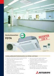
E/0304/31A/32
20.4 ALUMINIUM CASING - CVCAL<br />
With this option, casing of the unit is made of aluminium instead of standard steel zinc<br />
plated sheet. As standard, aluminium casing is not painted.<br />
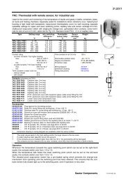
20.5 HIGH/LOW TEMPERATURE ALARM THERMOSTAT - TMC/TMF<br />
TMC (option for high temperature signal) and TMF (option for low temperature signal) are<br />
mechanical wall-mounted thermostats. They consist of thermostats with bi-metallic sensor<br />
element for switching signal transmitters. Their adjustable range is from 0°C to 60°C, contacts<br />
6A-250VAC. Type of contacts NC for TMC and NO for TMF.<br />
20.6 RELAY FOR POTENTIAL FREE COMMON ALARM SIGNAL (HIGH AND LOW<br />
PRESSURE, HIGH TEMPERATURE) - CA<br />
HP (high pressure alarm), LP (low pressure alarm) are not available as separate signals.<br />
CA, common alarm, is the consequence of the following alarms (high pressure+low<br />
pressure+high temperature). When one of these three symptoms appears, common alarm<br />
is activated to warn about possible faults on the unit.<br />
20.7 <strong>AIR</strong>FLOW SIGNAL - FL<br />
It consists of a differential air pressure switch. It provides a voltage-free signal by a N.O.<br />
contact when air flow pressure is different from the rated value, to indicate a fan malfunction.<br />
This value of intervention is factory pre-set according to the unit model.<br />
1 2<br />
M1/14<br />
3<br />
M1/15<br />
FL<br />
E/0304/31A/33
21. Residual Hazards and Emergency Information<br />
This unit was designed to reduce danger sources or situations to a minimum.<br />
These dangers arise from improper use of the product or from failure to comply with<br />
installation and operating instructions.<br />
All personnel who work on or near the unit must be familiar with these instructions.<br />
21.1 GENERAL SAFETY PROVISIONS<br />
All personnel charged with testing and maintaining the unit must be familiar with the following<br />
safety regulations:<br />
· Danger signs must be easily visible in areas of potential danger.<br />
· A visual supervision service must be set up in danger areas.<br />
· Supervisors must keep constant contact with controllers.<br />
· Transit zones, doors and ladders placed near the area where the unit is located must<br />
never be blocked.<br />
· Emergency exits must never be blocked.<br />
· Slippery areas that could be a potential risk for persons must be covered with anti-slip<br />
materials.<br />
· Proper tools and suitable procedures must be used for every specific activity.<br />
· Test tools and equipment must be kept in good order.<br />
· Personnel must have in-depth knowledge of methods and procedures to apply in case of<br />
fire (set up a fire extinguisher service in a handy position).<br />
· The following actions must be taken if a fire starts:<br />
- Switch off the electrical power supply to the component that is burning.<br />
- Switch off all fans so as to cut the oxygene supply.<br />
- Advise the appropriate department.<br />
21.2 HAZARDS ARISING FROM THE PRODUCT COMING INTO CONTACT WITH<br />
THINGS OR PERSONS<br />
· Danger point 1a) comes from movement by the fan. The grating mesh has a useful gap,<br />
between wires, smaller than 10 mm. Particles with smaller dimensions could be ejected<br />
by the fan blade.<br />
· Danger point 1b) comes from accidental contact with the heat exchanger since its<br />
aluminium fins can have sharp edges.<br />
21.3 HAZARDS ARISING FROM ELECTRICAL FAULTS<br />
21.3.1 SAFETY STANDARDS FOR ELECTRICAL EQUIPMENT<br />
Introduction<br />
The causes of electrical risks are well known and it is not difficult to prevent these risks by<br />
applying constant care and attention.<br />
Assigned personnel must be informed regarding potential dangers and trained regarding<br />
safety procedures in order to reduce the number of potential electrical accidents.<br />
E/0304/31A/34
21.3.2 TASKS ASSIGNED TO PLANT MANAGERS<br />
Plant managers must be informed regarding potential risks in the system and must<br />
superintend personnel that works with electrical equipment.<br />
Superintending tasks consist of localizing possible risk situations and investigating<br />
problems encountered by personnel when performing maintenance.<br />
Each defective component must be immediately repaired or replaced.<br />
The manager must insist on application of safety measures. He must not tolerate or accept<br />
deviations from these because this could cause harm to persons or to the machinery.<br />
21.3.3 HIGH VOLTAGE<br />
Contact with high voltage circuits can cause burns, shock, unconsciousness or even death<br />
for the persons involved.<br />
This problem can be caused by poor understanding of the dangers inherent to use of<br />
electrical devices.<br />
Damage to the human body, in this case, depends on the intensity of current, the duration<br />
of current and the path the current takes as it goes through the body.<br />
21.3.4 SAFETY STANDARDS TO COMPLY WITH WHEN THE EQUIPMENT IS<br />
SWITCHED OFF<br />
Interrupt the power supply to the unit before opening it.<br />
Make sure no electricity is present in the unit's circuits.<br />
Clean and dry the work area.<br />
Remove dowels, rings, brackets or metal parts which can hamper the job to be done or<br />
become potential conductors for electricity.<br />
Ground or short-circuit the terminals of the fan capacitors in the de-energized circuit.<br />
Remove fuses only after the circuit has been deactivated.<br />
21.3.5 SAFETY STANDARDS TO COMPLY WITH WHEN PERFORMING MAINTENANCE<br />
ON LIVE<br />
The following standards must be complied with, in addition to those stated at point 2.3.4<br />
above:<br />
· personnel must never work alone;<br />
· work should be done, if possible, using only one hand;<br />
· use only authorized procedures to perform by-passes at interlocks;<br />
· make sure assigned personnel are perfectly familiar with the machine's components and<br />
maintenance procedures before starting to work;<br />
· use protective gloves;<br />
· open all contacts that bring power to the equipment before measuring resistance values;<br />
· check that there is no high voltage in the low voltage circuits;<br />
· do not use magnetic tools near strong magnetic fields.<br />
21.3.6 SAFETY STANDARDS TO COMPLY WITH DURING MAINTENANCE<br />
If continuous operation is not required, the system must be turned off.<br />
E/0304/31A/35
Before beginning work, the following is required:<br />
· check the maintenance person and make sure he is not carrying objects which could<br />
become conductors;<br />
· inspect the work site and make sure the floor is clean an dry;<br />
· inspect work tools. These must be suited for the job to be done and be in good condition<br />
in order to permit safe maintenance;<br />
· measuring instruments must be periodically calibrated;<br />
· check work procedures before starting the job. Check the wiring diagram and get an<br />
overall picture of how the system is structured.<br />
It is necessary, while maintenance is being done:<br />
· for the maintenance person to be aware of which circuits are under high voltage;<br />
· no resistance measurements must be made on live circuits;<br />
· use only one hand when testing live circuits;<br />
· ground the terminals of the instrument before measuring live circuits;<br />
· always strictly comply with the suggestions mentionned above<br />
Maintenance can be held to be terminated when all components have been reinstalled<br />
and the unit has its original appearance.<br />
21.4 SAFETY STANDARDS TO COMPLY WITH WHEN WORKING ON REFRIGERATION<br />
CIRCUITS<br />
The refrigerant used for this machine can be dangerous if it is not properly used. Several<br />
precautions must be taken when handling this substance:<br />
· never release, store or use the refrigerant near open flames. The refrigerant is non-toxic.<br />
Contact with flames causes combustion which generates toxic gases that can corrode<br />
metal surfaces;<br />
· never expose the eyes to contact with the refrigerant since it can reach temperatures of<br />
-40°C;<br />
· never expose the skin to contact with the refrigerant. If this happens then the damaged<br />
part must be treated using the same procedures used in combination with frostbite and<br />
freezing;<br />
· avoid high concentrations of refrigerant since these can cause suffocation. In this case<br />
the person must be evacuated from the room and undergo artificial respiration;<br />
· avoid brazing or welding in the presence of refrigerant vapours;<br />
· do not place gas heating equipment or electrical radiators in places where refrigerant<br />
vapours may be present;<br />
· do not smoke;<br />
· do not overheat gas cylinders; do not exceed the refrigerant gas limit indicated on the<br />
technical data plate;<br />
· the cooling system must be handled with care as it may contain acids as a result of motor<br />
burn-out.<br />
Therefore, protective gloves, goggles and clothing must be worn.<br />
E/0304/31A/36
· eliminate pressure from the entire cooling system before brazing or welding. Welding<br />
when the circuit is under pressure is extremely dangerous due to the risk of the piping<br />
rupturing and molten material being projected by the refrigerant gas pressure.<br />
21.5 HAZARDS ARISING IN CASE OF FIRE<br />
There are no direct dangers.<br />
The refrigerant gas, in the presence of flames, generates toxic and corrosive substances.<br />
The way to prevent this risk, in view of the relatively small quantities of refrigerant contained<br />
in the machine, is to position the unit in adequately ventilated rooms.<br />
21.6 TOXIC SUBSTANCES<br />
The gas contained and used in this product is an ecological type of gas. A very small<br />
quantity is used and the circuit is hermetically sealed.<br />
All leaks with a loss of more than 15 grams per year are checked and eliminated during<br />
testing.<br />
The producer of the refrigerant gas states that gas concentrations inferior to 1 to 1000 are<br />
non toxic. When the machine is not installed in a well-ventilated or suitably large room and<br />
there is a substantial leak of refrigerant then the room should be ventilated and personnel<br />
should be sent out from the room.<br />
21.7 HAZARDOUS FLUIDS<br />
The unit does not contain any fluids which are hazardous to people.<br />
During operation, the A/C unit produces condensate which is drained into the environment<br />
if it is not dissipated by the dissipator. It is recommended to drain this fluid adequately by<br />
condensate lines so as to prevent possible hazards to people in the area.<br />
E/0304/31A/37
22. Disassembling the Unit<br />
WARNING!<br />
This unit contains refrigerant gas and a small quantity of lubricants (esters) in the<br />
compressor. These components are pollutants for the environment and must not<br />
be dispersed.<br />
Disassembling operations on this unit must only be done by experts<br />
Before starting to dismantle the unit check that it has been disconnected from<br />
electric mains.<br />
This unit must be disassembled by authorised organisations.<br />
STULZ is able and has equipment for disposing of these units and performing almost total<br />
recuperation of components without harm to the environment.<br />
While awaiting disposal the unit must be kept stored protected from weather.<br />
E/0304/31A/38
23. Faults, Probable Causes, Possible Remedies<br />
23.1 FAILS TO COOL<br />
.1 No part is working;<br />
.1 Lack of voltage to the unit;<br />
.1 Check that doors closed and switches are turned on.<br />
.2 Compressor, condenser fan and evaporator fan not working;<br />
.1 Cooling system has run out of refrigerant;<br />
.1 Contact STULZ technician or service department;<br />
.2 Compressor mechanically defective;<br />
.1 Contact STULZ technician or service department.<br />
.3 Compressor and condenser fan working, evaporator fan not working;<br />
.1 fan capacitor is defective;<br />
.1 Replace fan capacitor;<br />
.2 Evaporator fan defective;<br />
.1 Replace fan.<br />
.4 Condenser and evaporator fan working, compressor not working;<br />
.1 Where present, compressor circuit breaker defective;<br />
.1 Replace circuit breaker and check efficiency of the compressor's<br />
electrical parts;<br />
.2 Compressor start relay defective;<br />
.1 Replace compressor start relay;<br />
.3 Where present, start-up condenser defective;<br />
.1 Replace start-up condenser;<br />
.4 Compressor motor defective;<br />
.1 Contact STULZ refrigerant system technician or service department.<br />
.5 High pressure switch defective;<br />
.1 Contact STULZ refrigerant system technician or service department;<br />
.6 Where present, compressor remote control switch defective<br />
.1 Replace remote control switch.<br />
.5 Evaporator and condenser fan and compressor working;<br />
.1 Adjustment thermostat defective or calibrated at a temperature exceeding<br />
the temperature in the cabinet;<br />
.2 When present, anti-freeze thermostat defective.<br />
23.2 FAILS TO COOL SUFFICIENTLY<br />
.1 Evaporator fan working, compressor and condenser fan working<br />
intermittently<br />
.1 Service anti-freeze thermostat;<br />
.1 Clean evaporator<br />
.2 Check for any external causes which may limit the airflow to the<br />
inside circuit;<br />
.2 Where present, service low pressure switch;<br />
E/0304/31A/39
.1 Insufficient charge in the refrigerant circuit;<br />
Contact STULZ refrigerant system technician or service department;<br />
.3 Where present, solenoid valve defective;<br />
.1 Replace solenoid valve coil;<br />
.2 Contact STULZ refrigerant system technician or service department;<br />
.2 Condenser fan, evaporator fan working, compressor working<br />
intermittently;<br />
.1 Where present, service high pressure switch;<br />
.1 Room temperature exceeding maximum temperature as shown on<br />
technical data plate;<br />
.1 Ventilate room;<br />
.2 Contact STULZ service department;<br />
.2 Dirty air filter,<br />
.1 Clean or, if necessary, replace dirty air filter;<br />
.3 Dirty condenser;<br />
.1 Clean condenser;<br />
.4 Air short-circuit,<br />
.1 Check that no obstruction or obstacle are causing the expelled<br />
air to short circuit;<br />
.2 Check that requirements concerning minimum distance from a<br />
wall, from the ceiling, from the electric cabinet or from any other air<br />
cooling unit are as described in this manual;<br />
.2 Service compressor heat protector,<br />
.1 Air temperature in cabinet exceeding maximum temperature shown<br />
on unit's technical dataplate;<br />
.2 Same causes and relevant remedies as outlined under items<br />
22.2.2.1.1/2/3/4;<br />
.3 Evaporator fan working, condenser fan not working, compressor working<br />
intermittently;<br />
.1 fan capacitor is defective;<br />
.1 Replace fan capacitor:<br />
.2 Condenser fan defective;<br />
.1 Replace condenser fan:<br />
23.3 EXCESSIVE CONDENSATE FORMATION;<br />
.1 Cabinet with protection level lower than IP54;<br />
.1 Check that the self-adhesive seal between the cooling unit and the cabinet<br />
has been correctly applied;<br />
.2 Check that the unit's locking panels have been correctly installed;<br />
.3 Check that there are no openings in the cabinets.<br />
E/0304/31A/40