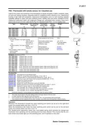
51.366/1 AVM 124S, 125S: Valve drive with Sauter Universal ...
51.366/1 AVM 124S, 125S: Valve drive with Sauter Universal ...
51.366/1 AVM 124S, 125S: Valve drive with Sauter Universal ...

Create successful ePaper yourself
Turn your PDF publications into a flip-book with our unique Google optimized e-Paper software.
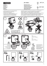
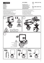
<strong>51.366</strong>/1<br />
<strong>AVM</strong> <strong>124S</strong>, <strong>125S</strong>: <strong>Valve</strong> <strong>drive</strong> <strong>with</strong> <strong>Sauter</strong> <strong>Universal</strong> Technology SUT<br />
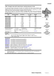
For controllers <strong>with</strong> continuous output (0...10V) or switched output (2-point or 3-point control). To operate<br />
through valves or three-way valves in series VXN/BXN, VUD/BUD, VUE/BUE. Characteristic (linear/equal-percentage/quadratic)<br />
can be set at the positioner.<br />
Housing of fire-retardant plastic, <strong>with</strong> stepping motor, electronic control unit, LED indicator and gears;<br />
body of gears and fixing bracket (for fitting the valve) are of cast zinc. Transparent lid of fire-retardant<br />
plastic. Electronic force-dependent cut-out by means of stops either in the <strong>drive</strong> or on the valve; automatically<br />
adapted to the valve stroke; coding switch for changing the characteristic and running time;<br />
external manual adjustment <strong>with</strong> power cut-off. Direction of operation can be changed over externally<br />
(power supply to terminal 2a or 2b, 01 or 02 respectively); electrical connection (max. 1.5 mm 2 ) by screw<br />
terminals; cable inlet M20×1.5; can be fitted in any position between vertical (upright) and horizontal.<br />
Type Running time<br />
[s]<br />
Stroke 5)<br />
[mm]<br />
Pushing force<br />
[N]<br />
Power Weight<br />
[kg]<br />
For valves <strong>with</strong> linear characteristic, can be switched over to equal-percentage<br />
<strong>AVM</strong> <strong>124S</strong> F132 30 / 60 / 120 7.5 800 24 V~ 2.1<br />
For valves <strong>with</strong> equal-percentage characteristic, can be switched over to linear<br />
<strong>AVM</strong> <strong>125S</strong> F132 30 / 60 / 120 8.0 800 24 V~ 2.1<br />
Positioner: 1)<br />
Control signal 1 0...10 V, Ri > 100 kΩ Starting point U 0 0 or 10 V<br />
Control signal 2 4...20 mA, Ri = 50 Ω Control span ΔU 10 V<br />
Position feedback signal 0...10 V, load > 2.5 kΩ Switching range Xsh 200 mV<br />
Power supply 24 V~ ± 20%, 50...60 Hz Degree of protection 3) IP 54 as per EN 60529<br />
24 V = 2) + 20% / - 10% Protection class III as per IEC 60730<br />
Power consumption 5 W 8.4 VA Wiring diagram <strong>AVM</strong> 124 A09856<br />
Wiring diagram <strong>AVM</strong> 125 A10451<br />
Max. media temperature 100 °C Dimension drawing M07430<br />
Permissible ambient temp. -10...55 °C Fitting instructions <strong>AVM</strong> 124 MV 505809<br />
Ambient humidity < 95 %rh Fitting instructions <strong>AVM</strong> 125 MV 506066<br />
<strong>with</strong>out condensation Declaration on materials MD <strong>51.366</strong><br />
Accessories<br />
0313529 001* Split-range unit for settings sequences. MV 505671; A09421<br />
0370880 001 Mechanical stroke indicator; MV 505517<br />
0370881 001* Auxiliary change-over contacts 4) , single; MV 505517<br />
0370882 001* Auxiliary change-over contacts 4) , single, and pot.2000 Ω, 1 W; 24 V; MV 505517<br />
0370882 006* Auxiliary change-over contacts 4) , single, and pot.1000 Ω, 1 W; 24 V; MV 505517<br />
0370883 001* Potentiometer 2000 Ω, 1 W; 24 V; MV 505517<br />
0370883 006* Potentiometer 1000 Ω, 1 W; 24 V; MV 505517<br />
0372249 001* Intermediate piece required for media temperature >100 °C for BXN / VXN<br />
(recommended for temperature < 10 °C); MV 505932<br />
0372460 001 Cable screw fitting (plastic M20×1.5) incl. locking nut and gasket, max. 2 pcs.<br />
*) Dimension drawing or wiring diagram are available under the same number<br />
100 %<br />
M<br />
Y07552<br />
Direction<br />
of operation 2<br />
Direction<br />
of operation 1<br />
0 %<br />
0 V Output signal y 10 V<br />
B07650<br />
1) Also for 2-point or 3-point, depending on connection<br />
2) 24V= only for 0...10V input signal<br />
3) Degree of protection IP 54 only <strong>with</strong> M20 cable screw fitting<br />
4) Infinitely variable; max. load 2 (1) A, 12...250 V∼, min. load 250 mA, 12 V~<br />
5) Maximum stroke of <strong>drive</strong> = 10.0 mm<br />
Operation<br />
Depending on how it is connected (see wiring diagram), the actuator can be used as a continuous<br />
<strong>drive</strong> (0...10V and/or 4...20 mA), a 2-point <strong>drive</strong> (open/close) or a 3-point <strong>drive</strong> (open/stop/close) <strong>with</strong><br />
intermediate position. When control signals 1 (3u, 03 respectively) and 2 (3i, 04 respectively) are connected<br />
simultaneously, the input <strong>with</strong> the highest value has priority.<br />
The running time can be matched to requirements using switches S1 and S2. The characteristic (equalpercentage,<br />
linear or quadratic) can be selected <strong>with</strong> switches S3 and S4. The <strong>AVM</strong> <strong>124S</strong> is combined<br />
<strong>with</strong> valves that have a linear basic characteristic such as the VXN and BXN valves. The <strong>AVM</strong> <strong>125S</strong> is<br />
combined <strong>with</strong> valves that have an equal-percentage basic characteristic such as the VUD, BUD, VUE<br />
and BUE valves. The <strong>AVM</strong> <strong>125S</strong> can be fitted on a valve <strong>with</strong> a linear characteristic (e.g.<br />
VUE 050F200), but you must pay attention to the position of the coding switches.<br />
Manual adjustment is done using the external handle. When this handle is pulled out, the motor cuts<br />
out. When the handle is put back in again, the <strong>drive</strong> again moves to the closed position and re-adjusts<br />
itself (continuous mode).<br />
Connected as a 2-point actuator<br />
Opening/closing can be effected via two wires. Power is applied to the <strong>drive</strong> via terminals 1 and 2b. On<br />
connecting power to terminal 2a, the valve’s control passage closes. When power is switched off, the<br />
<strong>drive</strong> goes to the opposite end position and opens the valve.<br />
<strong>Sauter</strong> Components<br />
7151366003 T6
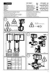
<strong>51.366</strong>/2 <strong>AVM</strong> <strong>124S</strong>, <strong>125S</strong><br />
Connected as a 3-point control unit<br />
By connecting power to terminal 2a / 01 or 2b / 02, the valve can be moved to any position. The coupling<br />
rod extends and opens the valve if power is applied to terminals 1 / MM and 2b / 02. It retracts<br />
and closes the valve if the power circuit is closed via terminals 1 / MM and 2a / 01.<br />
In the end positions (on hitting a stop in the valve or reaching the maximum stroke) or in the event of<br />
an overload, the electronic motor cut-off responds (no end switches). The direction of the stroke can be<br />
changed by swapping the power-supply wires over (2a, 2b / 01, 02).<br />
Connections for control voltage 0...10V and/or 4...20 mA<br />
The integrated positioner controls the <strong>drive</strong> as a function of the controller’s positioning signal y.<br />
The voltage signal of 0...10 V– is connected to terminal 3u / 03 and the current signal is connected to<br />
terminal 3i / 04.<br />
Direction of operation 1 (mains power at internal connection 2a / 01): the coupling rod extends and<br />
opens the valve (control passage) as the positioning signal rises.<br />
Direction of operation 2 (mains power at internal connection 2b / 02): the coupling rod retracts and<br />
closes the valve (control passage) as the positioning signal rises.<br />
The starting point and the control span are both pre-set.<br />
There is a split-range unit available (as an accessory) for setting partial ranges (only for control signal 1).<br />
After manual adjustments have been made, or when there is a power failure lasting longer than<br />
5 minutes, the <strong>drive</strong> re-adjusts itself automatically (always <strong>with</strong> a running time of 60 seconds).<br />
After power has been applied, the stepping motor moves to the lower stop, connects to the valve spindle,<br />
moves to the upper stop in the valve, thereby determining the closed position. Depending on the<br />
control voltage, any stroke between 0 and 8 mm can then be obtained. Thanks to the electronics unit,<br />
no steps are lost, and the <strong>drive</strong> needs no periodical re-adjustment. Parallel operation of more than one<br />
<strong>drive</strong> of the same type is guaranteed.<br />
The feedback signal y0 = 0...10V corresponds to the effective stroke of 0 to 8 mm.<br />
The valve’s characteristic can be selected using the coding switch. The characteristics can be generated<br />
only if the <strong>drive</strong> is used as a continuous <strong>drive</strong>. Other switches enable the running times to be set.<br />
These can be applied irrespective of whether the 2-point, 3-point or the continuous function has been<br />
chosen.<br />
Coding switch for running time selection<br />
<strong>AVM</strong> <strong>124S</strong>, <strong>AVM</strong> <strong>125S</strong><br />
Run time<br />
Switch coding<br />
per mm<br />
1 2 3 4<br />
3,75 s On<br />
30 s ± 1<br />
Off<br />
Run time for<br />
8 mm stroke<br />
7,5 s<br />
15 s<br />
1 2 3 4<br />
1 2 3 4<br />
On<br />
Off<br />
On<br />
Off<br />
On<br />
Off<br />
60 s ± 2<br />
120 s ± 4<br />
= factory setting<br />
B10706<br />
<strong>Sauter</strong> Components<br />
7151366003 T6
<strong>AVM</strong> <strong>124S</strong>, <strong>125S</strong> <strong>51.366</strong>/3<br />
Coding switch for characteristics selection<br />
<strong>AVM</strong> <strong>124S</strong><br />
Effective on valve<br />
Linear<br />
Quadratic Linear<br />
Linear<br />
<strong>Sauter</strong> Components<br />
7151366003 T6
<strong>51.366</strong>/4 <strong>AVM</strong> <strong>124S</strong>, <strong>125S</strong><br />
Coding switch for characteristics selection<br />
<strong>AVM</strong> <strong>125S</strong><br />
Desired<br />
character.<br />
curve<br />
Switch coding<br />
Characteristic<br />
curve for valve<br />
Characteristic<br />
curve for <strong>drive</strong><br />
Effective on valve<br />
v<br />
Stroke<br />
v<br />
1 2 3 4<br />
Equal<br />
percentage<br />
On<br />
Off<br />
Stroke<br />
Signal<br />
= %<br />
Signal<br />
v<br />
Stroke<br />
v<br />
Quadratic<br />
1 2 3 4<br />
On<br />
Off<br />
Stroke<br />
Signal<br />
x 2 lin<br />
Signal<br />
v<br />
Stroke<br />
v<br />
1 2 3 4<br />
Linear<br />
On<br />
Off<br />
Stroke<br />
Signal<br />
Signal<br />
v<br />
Stroke<br />
v<br />
1 2 3 4<br />
Equal<br />
percentage<br />
On<br />
Off<br />
Stroke<br />
Signal<br />
= %<br />
Signal<br />
v<br />
Stroke<br />
v<br />
Linear<br />
1 2 3 4<br />
On<br />
Off<br />
lin<br />
Stroke<br />
Signal<br />
Signal<br />
= factory setting<br />
B10708<br />
<strong>Sauter</strong> Components<br />
7151366003 T6
<strong>AVM</strong> <strong>124S</strong>, <strong>125S</strong> <strong>51.366</strong>/5<br />
LED indicator<br />
<strong>AVM</strong> <strong>124S</strong>, <strong>AVM</strong> <strong>125S</strong><br />
at a standstill<br />
(setpoint-=actual position,<br />
manual adjustment)<br />
<strong>drive</strong> moves in<br />
setpoint direction<br />
Split-range unit, accessory 0361529 001<br />
The starting point U 0 and the control span ΔU can be set using the potentiometer. This makes it possible<br />
to activate several regulating units in sequence or in cascade using the controller’s control signal.<br />
The input signal (partial range) is amplified into an output signal of 0...10V. This accessory can be fitted<br />
in the <strong>drive</strong>, or can be fitted externally in an electric distribution box.<br />
If the control signal (0...10V) is interrupted and direction of operation 1 is set, the valve closes fully<br />
(position 0%).<br />
Engineering and fitting notes<br />
The ingress of condensate, drops of water etc. along the valve spindle and into the <strong>drive</strong> should be<br />
prevented.<br />
With the electrical connection, you must also make sure that the cross-section of the supply line is<br />
adapted to the power and length. In any case, however, we recommend that the cross-section should<br />
not be less than a minimum of 0.75 mm 2 . The <strong>drive</strong> and valve are assembled by fitting together and<br />
tightening the cap nut <strong>with</strong>out further adjustment. The <strong>drive</strong> is supplied ex works in the middle position.<br />
The combination of stepping motor and electronics allows several actuators of the same type to be run<br />
in parallel.<br />
The maximum number of accessories that can be fitted is one stroke indicator plus one additional<br />
accessory: auxiliary contacts, potentiometer or combination, or split-range unit.<br />
Fitting outdoors. If the devices are fitted outdoors, we recommend that additional measures be taken<br />
to protect them against the effects of the weather.<br />
Additional technical information<br />
Transparent cover <strong>with</strong> lever for manual adjustment. The black housing holds the stepping motor and<br />
the electronic control unit. Underneath is the maintenance-free gear unit. By breaking out a pre-scored<br />
circle in the housing, it is possible to create an aperture to fit a second M20 cable screw fitting.<br />
Auxiliary change-over contacts<br />
Switch rating: max. 230V a.c.; min. current 20 mA at 20V<br />
Switch rating: 4...30V d.c.; current 1...100 mA<br />
Power consumption:<br />
Type Running time Condition active power P apparent power S<br />
s W VA<br />
<strong>AVM</strong> <strong>124S</strong> F132 30 Operating 3.3 4.8<br />
Standstill 1.75 2.8<br />
CE conformity<br />
EMC directive 89/336/EEC Machine directive 98/37/EEC/I/B<br />
EN 61000-6-1 EN 1050<br />
EN 61000-6-2<br />
EN 61000-6-3<br />
EN 61000-6-4<br />
<strong>Sauter</strong> Components<br />
7151366003 T6
<strong>51.366</strong>/6 <strong>AVM</strong> <strong>124S</strong>, <strong>125S</strong><br />
Wiring diagram<br />
<strong>AVM</strong> <strong>124S</strong> F132<br />
Accessories<br />
370881 370882<br />
4 5 6<br />
4 5 6<br />
10 11 12<br />
bei/si/if 230V<br />
bei/si/if 230V<br />
0%<br />
A01360a<br />
A06226a<br />
370883<br />
S1<br />
120s OFF<br />
120s ON<br />
60s ON<br />
60s OFF<br />
ON<br />
S2<br />
ON<br />
ON<br />
OFF<br />
OFF<br />
ON<br />
<strong>AVM</strong> <strong>124S</strong> F132<br />
S3<br />
S4<br />
lin. OFF ON<br />
lin. ON ON<br />
=% ON OFF<br />
OFF<br />
OFF<br />
ON<br />
ON<br />
<strong>AVM</strong> <strong>125S</strong> F132<br />
S3<br />
S4<br />
lin. OFF ON<br />
=% ON ON<br />
ON<br />
OFF<br />
=% OFF OFF<br />
ON<br />
ON<br />
10 11 12<br />
0%<br />
A01363<br />
A09856f<br />
MM 01/02 03<br />
Dimension drawing<br />
153<br />
0372249 001<br />
Ø33<br />
2,5<br />
Ø8<br />
203,5<br />
160,5<br />
60<br />
55,8<br />
5 15<br />
3,2<br />
10<br />
Ø42<br />
Ø16<br />
Z10214<br />
43<br />
>150<br />
114,1<br />
119,1<br />
Printed in Switzerland<br />
Right of amendment reserved<br />
N.B.: A comma between cardinal<br />
numbers denotes a decimal point<br />
© Fr. <strong>Sauter</strong> AG, CH-4016 Basle<br />
7151366003 T6 <strong>Sauter</strong> Components