Fatigue analysis of catenary contact wires for high speed trains
Fatigue analysis of catenary contact wires for high speed trains
Fatigue analysis of catenary contact wires for high speed trains

Create successful ePaper yourself
Turn your PDF publications into a flip-book with our unique Google optimized e-Paper software.
Challenge E: Bringing the territories closer together at <strong>high</strong>er <strong>speed</strong>s<br />
In France, some fatigue failures have already occurred on the overhead <strong>contact</strong> line between Paris<br />
and Lyon. This overhead line was replaced after only 29 years <strong>of</strong> use because fatigue failures took<br />
place under the junction claws. This component, commonly used in maintenance on classical lines,<br />
appeared to be inadequate when used on <strong>high</strong> <strong>speed</strong> lines. Its heavy weight and its <strong>high</strong> stiffness<br />
produce important dynamic loads and arcing with the pantograph passage. A modification <strong>of</strong> the<br />
maintenance procedure limits the number <strong>of</strong> settled claws and their duration, but the fatigue could<br />
take place on other lines.<br />
Indeed, the French network <strong>speed</strong> rising tendency requires an increase <strong>of</strong> the mechanical tension in<br />
the <strong>contact</strong> wire and this parameter heightens the fatigue failure phenomenon.<br />
The RTRI 1 , one <strong>of</strong> the research departments <strong>of</strong> Japan railways, studied the fatigue failure <strong>of</strong> the<br />
<strong>contact</strong> wire <strong>for</strong> a long time, see [1], [2] and [3]. They developed a specific test bench and per<strong>for</strong>med<br />
inline tests in order to measure and study the stress cycles in the <strong>contact</strong> wire. A comparison <strong>of</strong> the<br />
different approaches is led over the partnership between RTRI and SNCF.<br />
In this paper, we show the numerical study developed by SNCF using experimental results <strong>of</strong> RTRI as<br />
reference. The numerical study was carried out using OSCAR ©2 , the pantograph-<strong>catenary</strong> dynamic<br />
interaction simulation s<strong>of</strong>tware developed at SNCF and based on Finite Elements (FE) method [4].<br />
This tool is used to compute dynamic loads in the <strong>catenary</strong> using 1D finite element and to deduce the<br />
zone <strong>of</strong> maximum uniaxial stresses along the <strong>catenary</strong>. A fully 3D <strong>contact</strong> wire model <strong>of</strong> this selected<br />
zone is then built to study the multiaxial stress history in the <strong>contact</strong> wire section [5].<br />
2 Preliminary <strong>analysis</strong><br />
In this section, results <strong>of</strong> inline fatigue failure obtained on the French network and on the test bench <strong>of</strong><br />
RTRI are compared. Using this preliminary <strong>analysis</strong>, it appears that the phenomena are complex and<br />
difficult to predict.<br />
Indeed, <strong>contact</strong> wire failure which occurred inline (next to a claw) are different from those obtained<br />
using the test bench <strong>of</strong> RTRI. In both cases, the fatigue failure process follows three stages: crack<br />
initiation, crack propagation and failure. This last step occurs when the material that has not been<br />
affected by the crack cannot withstand the applied stress. One can determine material failed by<br />
fatigue by examining the appearance <strong>of</strong> the fracture. A fatigue fracture will have two distinct regions;<br />
one being smooth or burnished as a result <strong>of</strong> the rubbing <strong>of</strong> the bottom and top <strong>of</strong> the crack; the<br />
second is granular, due to the rapid failure <strong>of</strong> the material. These visual clues may be seen in Figure 3<br />
and Figure 5a but these figures illustrate significant differences between test bench and inline failure.<br />
2.1 Contact wire fatigue fracture on test bench<br />
The RTRI research department built a specific test bench to study fatigue breakage phenomenon [2].<br />
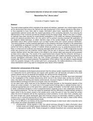
This test bench described in the Figure 2 was designed to reproduce realistic operation conditions by<br />
using a sample <strong>of</strong> real <strong>contact</strong> wire, by adding a tensile load on the <strong>contact</strong> wire to obtain the relevant<br />
mean stress and by applying a representative bending stress controlled by de<strong>for</strong>mation.<br />
Considering the test is per<strong>for</strong>med on a sample <strong>of</strong> a real <strong>contact</strong> wire, without any machining and thus<br />
with a constant section, a three bending point bench was chosen to <strong>for</strong>ce the fatigue failure to take<br />
place under the oscillating roller as described in Figure 2. In this way, it is easier to stick sensors<br />
close to the crack initiation point.<br />
Figure 2. RTRI test bench <strong>for</strong> OCL <strong>contact</strong> wire study [2].<br />
1 Railway Technical Research Institute<br />
2 OSCAR : Outil de Simulation du CAptage pour la Reconnaissance des défauts