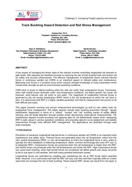
Track Buckling Hazard Detection and Rail Stress Management
Track Buckling Hazard Detection and Rail Stress Management
Track Buckling Hazard Detection and Rail Stress Management

You also want an ePaper? Increase the reach of your titles
YUMPU automatically turns print PDFs into web optimized ePapers that Google loves.
Challenge C: Increasing Freight capacity <strong>and</strong> services<br />
<strong>Track</strong> <strong>Buckling</strong> <strong>Hazard</strong> <strong>Detection</strong> <strong>and</strong> <strong>Rail</strong> <strong>Stress</strong> <strong>Management</strong><br />
Andrew Kish, Ph.D.<br />
President- K<strong>and</strong>rew Inc. Consulting Services<br />
Peabody, MA, USA<br />
Phone: 978-535-3342<br />
Email: k<strong>and</strong>rewinc@aol.com<br />
Ryan S. McWilliams<br />
Vice President-Technology & Business Development<br />
Salient Systems, Dublin, OH, USA<br />
Phone: 719-337-5852<br />
Email: rmcwilliams@salientsystems.com<br />
Harold Harrison<br />
Salient Systems - Technology Consultant<br />
Friday Harbor, WA, USA<br />
Phone: 360-317-8505<br />
Email: h_sqd@salientsystems.com<br />
ABSTRACT<br />
A key aspect of managing the stress state of the railroad involves controlling longitudinal rail stresses to<br />
safe levels. <strong>Rail</strong> networks are therefore focused on reducing the risk of both buckled track <strong>and</strong> broken rail<br />
for safety <strong>and</strong> security enhancement. The efficient management of longitudinal stress induced thermal<br />
forces in continuous welded rail (CWR) is an important aspect of railroad safety <strong>and</strong> maintenance.<br />
Balancing such forces is a complex issue which requires intimate knowledge of many parameters which<br />
include track strength as well as environmental operating conditions.<br />
CWR track is prone to lateral buckling when the rails are under high compressive forces. Conversely,<br />
when high tensile forces dominate under cold temperature conditions, rail defect growth can cause rail<br />
fractures, weld failures <strong>and</strong> rail joints to pull apart. The magnitude of longitudinal thermal forces is<br />
governed by the rail neutral temperature (RNT) which is the rail temperature at which the net force is<br />
zero. It is well known that RNT is a highly variable parameter <strong>and</strong> that its measurement has proven to be<br />
both difficult <strong>and</strong> costly.<br />
This paper presents evolving <strong>and</strong> proven measurement technologies as well as new safety tools for<br />
longitudinal force management. The safety aspects include track buckling prevention through hazard<br />
identification diagnostics in terms of a “yellow”, “orange” <strong>and</strong> “red” buckling margin of safety (BMS)<br />
warning, <strong>and</strong> rail break detection through sudden stress discontinuity (interruption) measurements. The<br />
maintenance aspects include providing <strong>and</strong> applying data for rail defect/break repairs when readjusting<br />
RNT to safe values in various operation conditions, <strong>and</strong> providing data for curve realignment <strong>and</strong> stability<br />
improvement through more efficient RNT management. The applications are illustrated through case<br />
study examples.<br />
1.0 Introduction<br />
Prevention of excessive longitudinal thermal forces in continuous welded rail (CWR) is an important track<br />
maintenance <strong>and</strong> safety issue. Thermal forces are generated when the rail temperature varies from the<br />
rail’s neutral temperature (RNT) i.e. the rail temperature at which the longitudinal force is zero, which is<br />
typically the rail’s installation or fastening temperature. (Note: common terminology also uses SFT <strong>and</strong> T N<br />
to designate RNT). Compressive forces are produced when the rail temperature is higher than the RNT,<br />
<strong>and</strong> tensile forces are produced when the rail temperatures are below the RNT. High compressive forces<br />
can cause track buckling, while high tensile forces can accelerate rail defect growth <strong>and</strong> cause rail joints<br />
to fail or pull apart in cold weather, with both being potential derailment causes.<br />
Longitudinal forces are controlled by installing <strong>and</strong> maintaining the rail at RNT levels within specified<br />
limits. However, it is a well known fact that the RNT will vary over time <strong>and</strong> that it typically shifts to a lower<br />
value that can increase the risk of track buckling. These lowered RNT values can result from rail repair or<br />
1
Challenge C: Increasing Freight capacity <strong>and</strong> services<br />
other maintenance work undertaken during cold weather <strong>and</strong> from excessive rail movement. A key<br />
impediment to knowing these low <strong>and</strong> potentially dangerous RNTs is a lack of adequate measurement<br />
capability which has eluded researchers for the past three decades. There have been several<br />
measurement concepts/techniques proposed <strong>and</strong> evaluated over the years with mixed results. These<br />
included techniques based on various physics concepts as illustrated in Figure 1.<br />
RNT Measurement Concepts/Issues<br />
Concepts Researched<br />
• Mechanical/electrical<br />
resistance strain gage<br />
• <strong>Rail</strong> uplift<br />
• <strong>Rail</strong> vibration<br />
• Vibrating wire/filament<br />
• Ultrasonic wave<br />
• Acoustic wave<br />
• Electromagnetic/acoustic<br />
wave (EMAT)<br />
• Magnetic permeability:<br />
(Barkhausen noise)<br />
(Magnetostriction)<br />
• X-ray diffraction<br />
Measurement Difficulties<br />
• Accuracy Issues:<br />
sensitivity to rail<br />
microstructure, residual<br />
stresses, track parameters;<br />
hard to get force/RNT from<br />
stress; “zeroes” required<br />
• Don’t provide real-time,<br />
continuous data output<br />
• Not nondestructive <strong>and</strong><br />
not easily deployable<br />
• No direct applicability<br />
to railroad maintenance<br />
<strong>and</strong> safety practices<br />
Figure 1 – Summary of RNT Measurement Concepts<br />
The key compromising aspects being (1) measurement accuracy, (2) ease of deployment, (3) providing<br />
continuous data on a real time basis, <strong>and</strong> (4) having direct applicability to railroad maintenance <strong>and</strong><br />
safety. Although several concepts partially fulfill these needs, the US Salient System’s <strong>Rail</strong> <strong>Stress</strong> Monitor<br />
(RSM) <strong>and</strong> its supportive <strong>Stress</strong>Net TM data base system have evolved to be the most responsive to the<br />
above needs. The RSM <strong>and</strong> its <strong>Stress</strong>Net TM technology have been developed <strong>and</strong> tested over twenty-five<br />
years of R&D, <strong>and</strong> have been recently exp<strong>and</strong>ed to support specific industry needs to not only measure<br />
RNT but interpret it for practical application to enhance overall CWR safety <strong>and</strong> performance. More<br />
specifically the RSM <strong>and</strong> <strong>Stress</strong>Net TM technology:<br />
<br />
<br />
<br />
<br />
<br />
Measures longitudinal force <strong>and</strong> RNT<br />
Detects rail breaks <strong>and</strong> track buckles<br />
Alerts on potential buckling hazards<br />
Enables more effective rail break/defect repairs<br />
Monitors rail joint condition<br />
In this paper several of these applications will be discussed with a particular emphasis on track buckling<br />
prevention through potential hazard identification diagnostics in terms of a “green”, “yellow”, “orange” or<br />
“red” buckling hazard warning.<br />
2.0 The RSM-<strong>Stress</strong>Net TM System (The RSM Technology)<br />
The rail-mounted hardware represents continuing evolving technology developments starting with a<br />
stress measurement circuit first developed at Battelle Columbus Laboratories in the early eighties [1, 2,<br />
2
Challenge C: Increasing Freight capacity <strong>and</strong> services<br />
3], <strong>and</strong> culminating in today’s expedient <strong>and</strong> railroad friendly iPod/iPhone based data acquisition system.<br />
The system is based on current radio technology <strong>and</strong> novel antenna designs that allow for a seamless<br />
collection process in a hardened design capable of surviving normal freight railroad operations <strong>and</strong><br />
maintenance with a power management system that allows 10+ year useful life, <strong>and</strong> the ability to collect<br />
the data with a variety of intermediate devices, including:<br />
<br />
<br />
<br />
<br />
H<strong>and</strong> held iPod/iPhone reader carried by a track inspector<br />
End of Train (EOT) device<br />
High rail inspection vehicle<br />
Wayside reader<br />
Figure 2 below shows the various uses <strong>and</strong> deployment options of the RSM-<strong>Stress</strong>Net TM system.<br />
RSM Deployment Options: When <strong>and</strong> Where?<br />
• When installing new rail<br />
• When making rail break/defect repairs<br />
• When destressing “hot” rail<br />
• In curves to manage lateral stability<br />
• At locations where fastener conditions are subst<strong>and</strong>ard<br />
• At locations of high stress build-up (approaches to<br />
bridges, special track work, tunnels, etc.)<br />
• In high tonnage lines to manage speed restrictions<br />
• In high-speed passenger lines for RNT safety monitoring<br />
• At joints for performance evaluation<br />
3.0 RNT Monitoring <strong>and</strong> <strong>Rail</strong> Break <strong>Detection</strong><br />
Figure 2 – Deployment Options for the RSM<br />
Figure 3 is an example of a <strong>Stress</strong>Net TM output of 5 years of RSM data at one location of Union Pacific test<br />
segment of newly laid CWR on a 2 degree (875 m radius) concrete tie track curve experiencing 230 MGTs<br />
of annual tonnage where both rails were instrumented with RSMs. The data show the RNT variation with<br />
time for the two rails (red for the low rail <strong>and</strong> green for the high rail) exhibiting the key features of: the overall<br />
RNT behavior trends, the daily variations (the shaded data <strong>and</strong> tooth-like spikes), the detection <strong>and</strong><br />
influences of three rail breaks on the high rail (as shown by the sudden drop in RNT as denoted by RB1,<br />
RB2 <strong>and</strong> RB3), <strong>and</strong> the influence of track maintenance involving surfacing <strong>and</strong> lining. To get a more detailed<br />
look at a rail break scenario, Figure 4 shows an exp<strong>and</strong>ed view of RB1 <strong>and</strong> RB2 data taken by the RSM<br />
closest to the breaks. Further inspection of Figure 4 shows that the low rail (red data) is relatively stable in<br />
terms of RNT variation (ignoring the daily changes - tooth-like spikes). The high rail (green) data, however,<br />
show the dramatic influences of rail breaks as indicated by the sudden discontinuity in RNT. The influence<br />
of interim joint repairs is also evident in terms of large daily RNT shifts due to joint-gap movement with<br />
temperature as shown by A <strong>and</strong> B. Finally, the green dashed arrow shows the effects of joint welding <strong>and</strong><br />
RNT restressing to the target RNT, <strong>and</strong> its effectiveness. Thus RNT knowledge <strong>and</strong> RNT monitoring during<br />
rail repair <strong>and</strong> readjustment is highly essential in CWR repair <strong>and</strong> maintenance, hence to more effectively<br />
managing the repair of broken <strong>and</strong> defective rail. Some inherent difficulties with these repair procedures are<br />
briefly outlined below in context of rail break mechanics.<br />
Daily RNT<br />
Variation<br />
2°(875m) Curve<br />
Low <strong>Rail</strong><br />
50<br />
Ne utra l Tempe ra ture (°F)<br />
3<br />
High <strong>Rail</strong><br />
Cell Phone Outage<br />
&<br />
RSM Refurbishment<br />
40<br />
30<br />
Ne utra l Temperature (
Challenge C: Increasing Freight capacity <strong>and</strong> services<br />
Figure 3 – Five Years of RSM Data on the Union Pacific<br />
50<br />
40<br />
Neutral Temperature (°F)<br />
RB1<br />
A<br />
RB2<br />
B<br />
30<br />
20<br />
Neutral Temperature (°C)<br />
2°(875m) Curve<br />
Low <strong>Rail</strong><br />
10<br />
High <strong>Rail</strong><br />
0<br />
Calendar Days<br />
Figure 4 – RNT Behavior in <strong>Rail</strong> Breaks<br />
4.0 <strong>Rail</strong> Break Mechanics, Repair <strong>and</strong> Restressing<br />
A major reason for the reduced <strong>and</strong> possibly unsafe neutral temperatures is the difficulty in resetting the<br />
RNT to the desired target value after a rail break or after a rail defect removal. The fundamentals of rail<br />
break mechanics are discussed in [4, 5], while Figure 5 illustrates the basics. It is a well known that when<br />
the rail is broken or cut for defect removal the RNT drops to the temperature of the rail when the break/cut<br />
occurs. For example, in Figure 5 when the rail breaks at 40°F(4°C) its RNT is 40°F (4°C) at that location.<br />
Additionally in this case, the rail break/cut influence is experienced for a track length exceeding 635 ft<br />
(194m) on either side of the break/cut as indicated by L d . As shown in [4, 5], these L d ’s can be on the<br />
4
Challenge C: Increasing Freight capacity <strong>and</strong> services<br />
order of 200–1200 ft (60–365 m) depending on the tensile force in the rail <strong>and</strong> on the rail/fastener’s<br />
longitudinal resistance.<br />
<strong>Rail</strong> Break/Cut RNT Profile<br />
T Break =40°F(4°C); SFT PreBreak =100°F (38°C); Gap=3in (7.6cm)<br />
RNT(°F)<br />
Pre-Break RNT = 100°F (38°C)<br />
RNT Locked in After<br />
Joint Closes<br />
100<br />
80<br />
Add<br />
3 in<br />
<strong>Rail</strong><br />
60<br />
T BR = 40°F<br />
3 in<br />
136#<strong>Rail</strong><br />
Timber Ties<br />
40<br />
20<br />
RNT Profile<br />
Just After<br />
The Break/Cut<br />
L d =635 ft (194m)<br />
900 800<br />
700<br />
600<br />
500<br />
400<br />
300<br />
200<br />
100<br />
0<br />
Distance from break (ft)<br />
100 200 300 400 500 600 700 800 900<br />
Figure 5 – <strong>Rail</strong> Break/Cut RNT Profiles<br />
The resulting rail gaps require closure by “adding rail” through a rail-plug insertion. Note that as shown in<br />
[4] closing the gap by pulling rail together is generally not an effective procedure since it might only<br />
restore the RNT to what it was in the rail prior to the break/cut, which may be much lower than the<br />
required target RNT. Adding rail through a plug insertion, however, does result in locking in the reduced<br />
RNT as indicated by the green RNT profile. It is this reduced RNT profile that is required to be readjusted<br />
before the onset of warm temperatures to avoid buckling prone conditions. The usual readjustment is<br />
made by cutting rail out <strong>and</strong> unfastening a prescribed length of rail at warmer temperatures. As indicated<br />
in [4, 5], the basic difficulty with this procedure is that the “correct” amount of rail to cut out <strong>and</strong> the<br />
“correct” unfastening lengths required are not known because the reduced RNT profile requiring<br />
adjustment is not known. The Salient RSM-<strong>Stress</strong>Net TM System can be applied to provide this knowledge,<br />
thus promoting a more effective management of rail break/defect removal repairs in terms of RNT<br />
readjustment. Specifically, the RSM-<strong>Stress</strong>Net TM System:<br />
<br />
<br />
<br />
<br />
Determines <strong>and</strong> monitors the RNT after plug/joint interim repair<br />
Alerts on when to return for the final repair/RNT readjustment to avoid a buckling prone condition<br />
(see <strong>Buckling</strong> <strong>Hazard</strong> description in next Section)<br />
Provides information on how to readjust to the desired RNT<br />
Provides information on effectiveness of the RNT readjustment<br />
One such application is shown in Figure 6 where the RSM data shows the specifics of rail break (RB3<br />
shown in Figure 3) repair on the Union Pacific test site. The RSM measured RNT data clearly shows the<br />
interim joint’s RNT of 60°F (16°C) to be readjusted. Without RSM/RNT measurement this would not be<br />
known, hence the amount of rail to cut out <strong>and</strong> unfasten would also be not known. RSM data also shows<br />
the effectiveness of the readjustment procedure <strong>and</strong> tracks the subsequent RNT condition.<br />
UP South Morrill Sub <strong>Rail</strong> Break on 2/8/06 , Joint Repair <strong>and</strong> RNT<br />
Readjustment As Monitored By <strong>Rail</strong> <strong>Stress</strong> Module (RSM)<br />
5<br />
RNT<br />
Readjustment<br />
50<br />
40<br />
<strong>Rail</strong> Break<br />
30<br />
emp (° F)<br />
Joint Repair RNT<br />
40°F (4°C)<br />
Joint RNT<br />
60°F (16°C)<br />
20<br />
RNT <strong>and</strong>
Challenge C: Increasing Freight capacity <strong>and</strong> services<br />
Figure 6 – RNT Monitoring <strong>and</strong> Readjustment during a <strong>Rail</strong> Break <strong>and</strong> Repair<br />
5.0 <strong>Track</strong> <strong>Buckling</strong> <strong>Hazard</strong> <strong>Detection</strong><br />
With the annual buckle derailments in the US ranging from 20 - 40 at a cost of over $10M per year, the<br />
prevention of track buckle caused derailments remains a key industry goal. <strong>Rail</strong>road efforts are<br />
continuing to focus on improving buckling prevention practices <strong>and</strong> on to better identifying buckling prone<br />
conditions. To assist in these efforts Salient Systems has recently developed a “<strong>Buckling</strong> <strong>Hazard</strong> Index”<br />
which provides a warning on potential buckles in terms of a yellow, orange, or red alert. The yelloworange-red<br />
alerts are based on the track having a prescribed buckling margin of safety (BMS). The BMS<br />
is determined by the <strong>Stress</strong>Net TM system <strong>and</strong> is based on the RSM measured rail <strong>and</strong> neutral<br />
temperature data coupled with the track’s buckling strength evaluations. The latter is based on the<br />
Volpe/FRA “CWR-SAFE” model [6], a part of which has been incorporated into the <strong>Stress</strong>Net TM system,<br />
referred to as BUCKLE. The BMS is a numerical temperature index on how close the track is to a “critical”<br />
condition in accordance with theoretical developments in [7, 8]. For completeness, a brief review of<br />
buckling safety concepts <strong>and</strong> BMS are provided below.<br />
5.1 <strong>Buckling</strong> Safety Concepts for BMS Applications<br />
Figure 7 shows the fundamental safety concept <strong>and</strong> criterion for buckling prevention as detailed in [9], as<br />
well as applied by the UIC in line with [10, 11].<br />
T Bmax T Bmin<br />
Temperature increase<br />
above neutral<br />
Buckle<br />
Temperature increase<br />
above neutral<br />
Step 1 Step 2<br />
Buckle<br />
o<br />
Deflection<br />
o<br />
Deflection<br />
6<br />
Temperature increase<br />
above neutral<br />
T Bmax T Bmin<br />
Step 3<br />
Buckle<br />
<strong>Buckling</strong><br />
regime<br />
Temperature increase<br />
above neutral<br />
T Bmax T Bmin<br />
Step 4<br />
Buckle<br />
<strong>Buckling</strong><br />
regime<br />
Safe temperature<br />
increase
Challenge C: Increasing Freight capacity <strong>and</strong> services<br />
Figure 7- <strong>Track</strong> <strong>Buckling</strong> Stability Response <strong>and</strong> Safe Temperature Concept<br />
Step 1 shows the track lateral deflection from an initial line defect with amplitude o with temperature<br />
increase. Step 2 exhibits the theoretically determined buckling equilibrium curve (shown in dashed)<br />
identifying the upper <strong>and</strong> lower critical temperatures ΔT Bmax <strong>and</strong> ΔT Bmin . Step 3 shows that the actual<br />
buckling occurs at a temperature in a buckling regime bounded by the upper <strong>and</strong> lower critical<br />
temperatures, <strong>and</strong> Step 4 identifies the lowest point on the buckling response curve as the safe allowable<br />
temperature increase. According to theoretical concepts [5], at temperatures below this value buckling<br />
should not occur, <strong>and</strong> the track’s deflections are confined to the growth of the initial line defects with<br />
temperature. The safety criterion on track buckling prevention is based on this safe temperature value i.e.<br />
on the ΔT Bmin on the buckling response curve.<br />
<strong>Buckling</strong> prevention safety criterion then requires that rail temperature increase above neutral to be<br />
confined to values less than ΔT Bmin. Since ΔT Bmin is an analytically determined quantity based on theory<br />
<strong>and</strong> on track condition/parameter inputs, for additional safety considerations it is customary to add a<br />
safety factor on ΔT Bmin . For most heavy-haul applications this safety factor is typically 10°F (6°C) less<br />
than ΔT Bmin [9]. For the European rail network’s safety factors refer to [10, 11]. It is important to note that<br />
the safe temperature increase value, ΔT Bmin , <strong>and</strong> the buckling regime’s upper bound, ΔT Bmax , are highly<br />
track parameter/type/condition dependent, <strong>and</strong> are referenced to the track’s neutral temperature. Hence<br />
for buckling hazard detection both the safe allowable temperature (as modified by any additional safety<br />
factors) <strong>and</strong> the track’s RNT are required in accordance with the safety criterion that: thermal load <<br />
buckling strength, where the thermal load is based on the RNT, <strong>and</strong> the track strength is based on the<br />
safe allowable temperature.<br />
In line with the above, the buckling margin of safety (BMS) is defined as the reserve “buckling strength” in<br />
terms of the additional temperature or thermal load required to produce a buckling prone condition i.e.<br />
reaching the track’s safety limit. This is graphically illustrated in Figure 8.<br />
T<br />
T Bmax T Bmin<br />
T ALL<br />
T actual<br />
Safety Factor<br />
BMS = (T ALL – T actual )<br />
Buckle Amplitude<br />
7
Challenge C: Increasing Freight capacity <strong>and</strong> services<br />
5.2 <strong>Buckling</strong> <strong>Hazard</strong> Index<br />
Figure 8- <strong>Buckling</strong> Margin of Safety (BMS) Definition<br />
Salient’s <strong>Stress</strong>Net TM System has been recently upgraded to provide a buckling hazard warning based on<br />
the RSM’s RNT output. The warning is based on a “<strong>Buckling</strong> <strong>Hazard</strong> Index” which provides a color<br />
indexed alert in terms of a green, yellow, orange, or red conditions. The green-yellow-orange-red alerts<br />
are based on having a prescribed buckling margin of safety (BMS) where the BMS is determined by the<br />
<strong>Stress</strong>Net TM . This determination is based on the RSM provided rail <strong>and</strong> neutral temperature data, <strong>and</strong> on<br />
the track’s buckling strength as computed by BUCKLE. The BUCKLE algorithm based on the Volpe/FRA<br />
“CWR-SAFE” model (3), <strong>and</strong> it is customized for easy railroad use by requiring only simple input<br />
parameters readily available to the railroad engineer. The program determines the “allowable<br />
temperature increase”, <strong>and</strong> based on the RSM measured rail temperature <strong>and</strong> RNT it computes a<br />
buckling margin of safety (BSM). Based on the calculated BMSs falling into prescribed “safe”, marginally<br />
safe” or “unsafe” regimes in accordance with Table 1, alerts can be issued on a potential for an incipient<br />
buckle. Note that in Table 1 the green-yellow-orange-red BMS regimes are illustrative <strong>and</strong> provisional in<br />
line with current US practice, <strong>and</strong> are based on the RSM’s real time output <strong>and</strong> <strong>Stress</strong>Net’s real time<br />
application for BMS determination. Automated “triggers” can be developed for specific railroad property or<br />
network needs.<br />
Table 1 - Provisional Criterion for BMS Application to <strong>Hazard</strong><br />
Identification <strong>and</strong> Advisories<br />
BMS<br />
BMS<br />
Larger than 25°F<br />
(14°C)<br />
ACTION<br />
ACTION<br />
OK; no action<br />
Between 10 <strong>and</strong> 25°F<br />
( 6 <strong>and</strong> 14°C)<br />
Caution; advisory<br />
Between 0 <strong>and</strong> 10°F<br />
(0 <strong>and</strong> 6°C) Slow order; readjust RNT<br />
Less than 0<br />
Red flag; immediate attention<br />
5.3 <strong>Buckling</strong> <strong>Hazard</strong> Warning Example <strong>and</strong> Case Study<br />
Based on RSM/<strong>Stress</strong>Net TM data as outlined in Figures 2 <strong>and</strong> 3, buckling hazard evaluations were<br />
conducted for the Union Pacific at two RNT conditions for a maximum summer rail temperature of 140°F<br />
(60°C) application in line the green yellow-orange-red index definition. The results are shown in Figure 9<br />
where the left-h<strong>and</strong> side shows the RNT profile, while the right-h<strong>and</strong> side the <strong>Stress</strong>Net’s BUCKLE output<br />
providing the BMS <strong>and</strong> the hazard index. At RNT avg=103°F(40°C) a high BMS=50°F (28°C) is calculated<br />
showing the “green” condition at a rail temperature of 140°F (60°C) i.e. that at the track is not buckling<br />
prone till 140 + 50 =190°F (88°C). At a lower RNT avg = 75°F (24°C) BUCKLE output indicates a BMS=22°F<br />
(12°C) or a “yellow” alert i.e. that the track is not vulnerable to buckling till 140 + 22 =162°F (72°C). Based<br />
on such outputs the railroad can determine <strong>and</strong> apply remedial action as needed. For the Union Pacific,<br />
this test provided information on not needing summer slow orders. For additional hot-weather speed<br />
restriction concepts <strong>and</strong> applications refer to [12].<br />
8<br />
Is there a buckling hazard at T RAIL = 140°F (60° C)?<br />
RNT avg =103°F(40°C)
Challenge C: Increasing Freight capacity <strong>and</strong> services<br />
Figure 9 – Example of <strong>Buckling</strong> <strong>Hazard</strong> Warning<br />
6.0 Conclusions<br />
<strong>Track</strong> buckling hazard detection <strong>and</strong> rail stress management largely depend on the track’s RNT condition.<br />
Although techniques to measure <strong>and</strong> monitor RNT with sufficient accuracy have been lacking, a<br />
promising evolving technology based on continuous <strong>and</strong> real time RNT measurement system has been<br />
developed. The applications of this system’s measurements have been extended to cover several rail<br />
longitudinal stress management aspects, including rail break detection, improved rail break/defect<br />
removal repairs, <strong>and</strong> to a track buckling hazard detection <strong>and</strong> warning capability, all aimed at providing for<br />
more efficient CWR safety <strong>and</strong> maintenance strategies.<br />
7.0 References<br />
[1] H. D. Harrison, “Evaluation of Methods for Measurement of Longitudinal <strong>Rail</strong> Force in Unloaded<br />
<strong>Track</strong>”, Battelle Columbus Laboratories, Technical Memo, Contract No. DOT-FRA-9162, Task 2, 1981<br />
[2] H. D. Harrison, “Strain Gage Based Longitudinal <strong>Rail</strong> <strong>Stress</strong> Measurements at FAST”, Battelle<br />
Columbus Laboratories, Technical Note, Contract No. DOT-FRA-9162, October 12, 1983<br />
[3] D. R. Ahlbeck, H. D. Harrison, “Monitoring <strong>Rail</strong> Neutral Temperature <strong>and</strong> the Long Term Stability<br />
of <strong>Track</strong>”, presented at the American Society of Mechanical Engineers, Annual Winter Meeting, San<br />
Francisco, California, 1989<br />
9
Challenge C: Increasing Freight capacity <strong>and</strong> services<br />
[4] A. Kish, “Destressing/Restressing for Improved CWR Neutral Temperature <strong>Management</strong>”, in<br />
“Guidelines to Best Practices for Heavy Haul <strong>Rail</strong>way Operations: <strong>Track</strong>”, International Heavy Haul<br />
Association publication, 2009, pp. 6-58 to 6-73<br />
[5] A. Kish, G. Samavedam, “Improvements in CWR Destressing for Better <strong>Management</strong> of <strong>Rail</strong><br />
Neutral Temperature”, Paper presented at 2005 Transportation Research Board Annual Conference -<br />
January 2005, <strong>and</strong> in Journal of the Transportation Research Board #1916, pp 56-65, 2005<br />
[6] A. Kish, W. Mui, “CWR-SAFE”, Software <strong>and</strong> User’s Guide, February 2001, US DOT/Volpe Center<br />
[7] A. Kish, “<strong>Track</strong> Lateral Stability”, in “Guidelines to Best Practices for Heavy Haul <strong>Rail</strong>way Operations:<br />
<strong>Track</strong>”, International Heavy Haul Association publication, 2009 pp. 1-71 to 1-84<br />
[8] A. Kish, G. Samavedam, “Dynamic <strong>Buckling</strong> of Continuous Welded <strong>Rail</strong> <strong>Track</strong>: Theory, Tests,<br />
<strong>and</strong> Safety Concepts,” Transportation Research Record No. 1289, “<strong>Rail</strong>: Lateral <strong>Track</strong> Stability 1991”<br />
[9] A. Kish, G. Samavedam, “<strong>Track</strong> <strong>Buckling</strong> Prevention: Theory, Safety Concepts <strong>and</strong> Applications”,<br />
DOT/FRA/ORD Final Report, October 2004, in FRA publication<br />
[10] A. Kish, et al, “Laying <strong>and</strong> Maintenance of CWR <strong>Track</strong>”, Union of International <strong>Rail</strong>ways (UIC) Code<br />
720, ERRI D202/RP#10, Chapter 6, April 1999, Utrecht, The Netherl<strong>and</strong>s<br />
[11] Union of International <strong>Rail</strong>ways (UIC) Code 720R, “Laying <strong>and</strong> Maintenance of CWR <strong>Track</strong>”, 2nd<br />
Edition, December 2002<br />
[12] A. Kish, D. Clark, “<strong>Track</strong> <strong>Buckling</strong> Derailment Prevention through Risk-Based Train Speed<br />
Reductions”, 2009 AREMA Annual Conference, Chicago, September 2009<br />
10