Genelec 1029A Bi-amplified Monitoring System - Eberle AV
Genelec 1029A Bi-amplified Monitoring System - Eberle AV
Genelec 1029A Bi-amplified Monitoring System - Eberle AV

You also want an ePaper? Increase the reach of your titles
YUMPU automatically turns print PDFs into web optimized ePapers that Google loves.
<strong>1029A</strong><br />
DATA SHEET<br />
<strong>Genelec</strong> <strong>1029A</strong><br />
<strong>Bi</strong>-<strong>amplified</strong> <strong>Monitoring</strong> <strong>System</strong>
<strong>1029A</strong> <strong>1029A</strong> <strong>Bi</strong>-<strong>amplified</strong> <strong>Bi</strong>-<strong>amplified</strong> Active Active <strong>Monitoring</strong> <strong>Monitoring</strong> <strong>System</strong><br />
<strong>System</strong><br />
SYSTEM<br />
SYSTEM<br />
The <strong>Genelec</strong> <strong>1029A</strong> is a very compact<br />
bi-<strong>amplified</strong> active monitor<br />
system, which has performance<br />
comparable to much larger systems.<br />
The vented speaker<br />
enclosure contains an amplification<br />
unit. This unit includes an<br />
active electronic crossover, overload<br />
protection circuitry and two<br />
power amplifiers, one for each<br />
driver. The system's excellent dispersion<br />
and precise imaging,<br />
together with its compact size,<br />
make it ideal for near field monitoring,<br />
mobile vans, home studios,<br />
multimedia and home theatres.<br />
The <strong>Genelec</strong> <strong>1029A</strong> has been specially<br />
designed to have a sufficient<br />
LF extension (-3dB at 68Hz) for<br />
most monitoring applications.<br />
However if greater SPL's and a<br />
lower cutoff frequency are required,<br />
it can be complemented<br />
with the 1091A subwoofer, which<br />
has a lower cutoff point of 38Hz.<br />
<strong>Genelec</strong>’s unique Directivity Con-<br />
trol Waveguide (DCW) technology<br />
is used to provide excellent<br />
stereo imaging and frequency<br />
balance, even in difficult acoustic<br />
environments. Versatile tone controls<br />
allow further matching of the<br />
system to its surroundings. A pair<br />
of <strong>1029A</strong>'s can produce peak<br />
acoustic levels of over 110 dB SPL<br />
at 1m. The speakers may be used<br />
in a vertical or horizontal orientation.<br />
INTEGRATED<br />
INTEGRATED<br />
INTEGRATED<br />
CONSTRUCTION<br />
CONSTRUCTION<br />
The <strong>1029A</strong> is very easy to set up<br />
and use, the only connections required<br />
are the mains supply and<br />
the line level input.<br />
The integrated design allows the<br />
amplifiers and the drivers to be<br />
calibrated as a single unit, eliminating<br />
the effects of component<br />
tolerances and ensuring consistent<br />
quality. The rugged cast<br />
aluminium cabinet has rounded<br />
corners and a hard-wearing<br />
painted outer surface.<br />
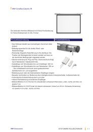
Figure 1: The <strong>1029A</strong> back panel, controls and connectors.<br />
Audio<br />
Input<br />
XLR<br />
1 2<br />
3<br />
1/ 4 "<br />
Jack<br />
INPUT AMPLIFIER<br />
Volume<br />
control<br />
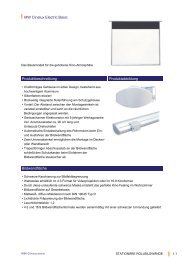
Figure 2: Block diagram showing active crossover filters, power<br />
amplifiers and driver units.<br />
CROSSOVER CROSSOVER FILTERS<br />
FILTERS<br />
APPLICATIONS<br />
APPLICATIONS<br />
Near Near Field Field <strong>Monitoring</strong><br />
<strong>Monitoring</strong><br />
The amplifier unit contains an active<br />
crossover, a feature more<br />
commonly used in large and expensive<br />
control room monitors.<br />
This is the ideal method for dividing<br />
the input signal between the<br />
driver units. The active crossover<br />
allows the overall response of the<br />
system to be optimized to an extent<br />
impossible with a passive<br />
system. To maintain uniform frequency<br />
balance in differing<br />
acoustic environments, special<br />
calibrated controls are included in<br />
the active crossover network.<br />
These controls include treble 'tilt',<br />
bass 'tilt' and bass 'roll-off'<br />
switches.<br />
Audio Audio Video Video Video Post Post Production<br />
Production<br />
Mobile Mobile Vans<br />
Vans<br />
Home Home Theaters<br />
Theaters<br />
Project Project / / Home Home Studios<br />
Studios<br />
Digital Digital Workstations<br />
Workstations<br />
Multimedia Multimedia Production Production / / Playback<br />
Playback<br />
CROSSOVER FILTER<br />
BASS<br />
ROLL-OFF<br />
Mains Input<br />
BASS TILT<br />
TREBLE TILT<br />
ON<br />
OFF<br />
Start/Stop<br />
Mute<br />
Power Supply<br />
circuits<br />
T-CAL<br />
B-CAL<br />
INPUT INPUT CONNECTORS<br />
CONNECTORS<br />
POWER AMPLIFIERS<br />
Treble<br />
Treble and Bass<br />
driver protection<br />
circuit<br />
Bass<br />
The input is made via a balanced<br />
XLR female or a balanced 1 /4" jack<br />
socket connector. The two input<br />
connectors offer great flexibility<br />
as they can be used in parallel.<br />
This offers the possibility of having<br />
two sources connected to the<br />
monitor at the same time. An<br />
additional configuration is using a<br />
single <strong>1029A</strong> to monitor a stereo<br />
output. See figures 3 and 4.<br />
The volume control is located on<br />
the front panel. This allows easy<br />
level matching with other audio<br />
equipment.
Figure 3: Using two sources.<br />
Figure 4: Using one monitor and a<br />
stereo source.<br />
AMPLIFIERS<br />
AMPLIFIERS<br />
The bass and treble amplifiers<br />
produce 40 W of output power<br />
each, with very low THD and IM<br />
distortion values. The amplifiers<br />
are designed to ensure the highest<br />
subjective sound quality<br />
currently possible. The amplifier<br />
unit also contains a protection circuit<br />
that monitors the output levels<br />
and prevents any damage to the<br />
drivers. This makes the system<br />
immune to overloads and spurious<br />
signals.<br />
DRIVERS<br />
DRIVERS<br />
A 19 mm ( 3 /4") metal dome tweeter<br />
is loaded by a DCW, and is used<br />
to reproduce the high frequencies.<br />
The DCW is integrated into<br />
the one piece cabinet front baffle.<br />
Figure 5: The reference axis lies<br />
between bass and treble drivers.<br />
The 130 mm (5") woofer is a bass<br />
cone driver mounted in a 4.5 litre<br />
vented cabinet. The -3 dB frequency<br />
is 68 Hz and the low<br />
frequency response extends<br />
down to 65 Hz (-6dB).<br />
Protective grills are positioned in<br />
front of both drivers. Magnetic<br />
shielding is standard on the <strong>1029A</strong>.<br />
Shielding is vital for applications<br />
such as video post production,<br />
where stray magnetic fields must<br />
be minimized.<br />
DCW DCW TECHNOLOGY<br />
TECHNOLOGY<br />
The revolutionary Directivity Control<br />
Waveguide (DCW) technology<br />
is a means of greatly improving<br />
the performance of a direct radiating<br />
multi-way loudspeaker<br />
under normal listening conditions.<br />
One of the basic aims is to match<br />
the performance of the drivers in<br />
terms of both frequency response<br />
and directivity. This results in a<br />
smoother overall frequency response<br />
on and off axis. In addition,<br />
the improved directivity control<br />
causes more direct sound and<br />
less reflected sound to be received<br />
at the listening position.<br />
This provides improved stereo<br />
imaging and ensures that the system<br />
is less sensitive to differing<br />
control room acoustics than conventional<br />
direct radiator design.<br />
The DCW Technology improves<br />
the drive unit sensitivity by +2 to<br />
+6 dB (depending on the particular<br />
application), thus also<br />
increasing the available system<br />
maximum sound pressure level.<br />
MOUNTING<br />
MOUNTING<br />
There are several possibilities for<br />
mounting the <strong>1029A</strong>. On the base<br />
of the monitor is a 3 /8" UNC threaded<br />
hole which can accommodate a<br />
standard microphone stand.<br />
There is a provision for an Omnimount®<br />
size 50 bracket,for which<br />
two M6x10mm screws are required.<br />
Alternatively the speaker<br />
can be hung on M4 screws with<br />
suitable heads by one of the three<br />
keyhole slots on the backpanel.<br />
The speaker can be hung in a<br />
horizontal or vertical position. Friction<br />
pads are provided for<br />
placement on a shelf or a stand.<br />
OPTIONS<br />
OPTIONS<br />
The <strong>1029A</strong> is available in three<br />
colours: black, grey and white.<br />
The driver's protective grilles,<br />
volume and power knobs and<br />
stickers on the back of the loudspeaker<br />
are black regardless of<br />
cabinet colour. Other options include<br />
wall and ceiling mounts,<br />
table stand and soft carrying bag.<br />
Ask your local <strong>Genelec</strong> dealer for<br />
more details.<br />
AUDIO PRECISION <strong>1029A</strong> LEVEL(dBr) vs FREQ(Hz)<br />
17 AUG 96 10:32:56<br />
100<br />
95<br />
90<br />
85<br />
80<br />
75<br />
70<br />
65<br />
60<br />
55<br />
100<br />
95<br />
90<br />
20 100 1k 10k 20k<br />
Figure 6: The upper curve group shows the horizontal directivity<br />
characteristics of <strong>1029A</strong> measured at 1 m. The lower curve is the total<br />
radiated power response. Uin=-20 dBu.<br />
AUDIO PRECISION <strong>1029A</strong> LEVEL(dBr) vs FREQ(Hz)<br />
23 SEP 96 10:24:33<br />
100<br />
95<br />
90<br />
85<br />
80<br />
75<br />
70<br />
65<br />
60<br />
55<br />
50<br />
BASS TILT<br />
2+3+4 OFF<br />
3 ON<br />
4 ON<br />
3+4 ON<br />
2+3+4 ON<br />
BASS ROLL-OFF<br />
Figure 7: The curves show the effect of the 'bass tilt', 'treble tilt' and 'bass<br />
roll-off' controls on the free field response.<br />
Figure 8: The <strong>1029A</strong>s and 1091A subwoofer.<br />
0 15<br />
30<br />
45<br />
TREBLE TILT<br />
1 OFF<br />
20 100 1k 10k 20k<br />
1 ON
SYSTEM<br />
SYSTEM<br />
SPECIFICATIONS<br />
SPECIFICATIONS<br />
Lower cut-off frequency, -3 dB: < 68 Hz<br />
Upper cut-off frequency, -3 dB: > 20 kHz<br />
Free field frequency response of system:<br />
70 Hz - 18 kHz (±2.5 dB)<br />
Maximum short term sine wave acoustic<br />
output on axis in half space, averaged<br />
from 100 Hz to 3 kHz:<br />
@ 1m > 100 dB SPL<br />
@ 0.5m > 106 dB SPL<br />
Maximum long term RMS acoustic output in<br />
same conditions with IEC weighted noise<br />
(limited by driver unit protection circuit):<br />
@ 1m > 98 dB SPL<br />
@ 0.5m > 104 dB SPL<br />
Maximum peak acoustic output per pair on<br />
top of console, @ 1 m from the engineer<br />
with music material:<br />
> 110 dB SPL<br />
Self generated noise level in free field<br />
@ 1 m on axis:<br />
< 10 dB (A)<br />
Harmonic distortion at 85 dB SPL @ 1m on<br />
axis:<br />
Freq: 75...150 Hz 150