HL670 - TAG Heuer Timing Systems
HL670 - TAG Heuer Timing Systems
HL670 - TAG Heuer Timing Systems

You also want an ePaper? Increase the reach of your titles
YUMPU automatically turns print PDFs into web optimized ePapers that Google loves.
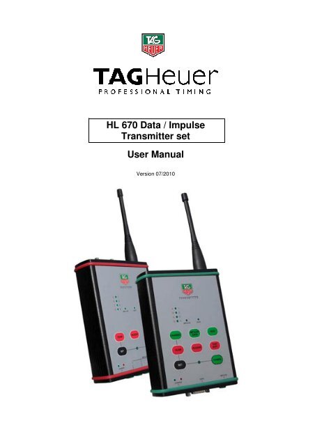
HL 670 Data / Impulse<br />
Transmitter set<br />
User Manual<br />
Version 07/2010
1. Global<br />
The Set <strong>HL670</strong> is ideal for transferring <strong>Timing</strong> Data and Impulses.<br />
Its 500mW emitting power and its licence free frequency range (869 Mhz) makes this<br />
device a powerful and simple to use system.<br />
<br />
<br />
Data / Impulse transmission system (500 Mw) which does not require a licence (free<br />
of use) in Europe (ISM Band 869 MHz – REC 70-03).<br />
Each Receiver can receive Impulses (simultaneously or not) from 4 Transmitters<br />
identified by the function "CHANNEL" (1 to 4).<br />
<br />
Up to 4 Teams can work (train) in the same area without disturbing each other thanks<br />
to the function "TEAM" which offers the possibility to code each system<br />
(A, B, C, D).<br />
It is also possible to use up to 16 transmitters with 4 receivers.<br />
<br />
When the receiver is switched on, it is possible that one or more green LED’s are on<br />
before that the transmitter(s) start to transmit. This detection system allows<br />
visualization of the quality of the received signal, but also the possible interferences<br />
coming from other radio transmission systems. If it is not possible to stop these<br />
interferences by moving the receiver, the transmission of Impulse cannot be<br />
guaranteed.<br />
Important Remark<br />
Don’t forget to register your product online at:<br />
http://www.tagheuer-timing.com/tools/product-register
1. Functions<br />
The Transmitter :<br />
9<br />
10<br />
6<br />
7<br />
5<br />
4<br />
8<br />
3<br />
2<br />
1<br />
11<br />
1. IMPULSE Input for timing Impulse (Start gate, photocell – working / closing contact). Respect the polarities.<br />
2. DATA Male Sub-D 9: RS232 input for DATA transfer<br />
3. POWER To switch on the receiver (press for 3 seconds on POWER). The green LED is on.<br />
To switch off the receiver, hold down SET and press POWER.<br />
4. SET To program the TEAM (A, B, C, D) and to switch off the receiver. Hold down SET during the changes.<br />
5. TEAM To check the programmed TEAM.<br />
To change the code, hold down SET and press TEAM.<br />
6. CHANNEL To check the programmed CHANNEL.<br />
To change the CHANNEL, hold down SET and press CHANNEL.<br />
7. TEST For testing the Impulse transmission only. The reception level will be displayed for 0.2 seconds on the<br />
receiver. You’ll also get an Impulse on the programmed output.<br />
8. TEST BATT To check the state of the battery. Press TEST BATT : The Battery level will be displayed with the 4 LED’s<br />
for 2 seconds.<br />
9. LED LED control panel which shows the programmed TEAM or CHANNEL. Also shows the transmitted Impulse.<br />
10. LED Shows the transmission mode : IMPULSE or DATA<br />
11. CHARGE Charging status Leds. The red led indicates that the Accu is charging. The charge is completed as soon as<br />
the green LED in on.
The Receiver<br />
9<br />
6<br />
7<br />
8<br />
1<br />
5 10<br />
4<br />
3<br />
2<br />
1. IMPULSE Output for timing Impulse (Start gate, photocell – working / closing contact). Respect the polarities.<br />
2. DATA Female Sub-D 9 : RS232 Output<br />
3. POWER To switch on the receiver (press for 3 seconds on POWER). The green LED is on. To switch off the<br />
receiver, hold down SET and press POWER.<br />
4. SET To program the TEAM (A, B, C, D) and to switch off the receiver. Hold down SET during the changes.<br />
5. TEAM To check the programmed TEAM. The green LED corresponding to the code A, B, C or D is on. To change<br />
the code, hold down SET and press TEAM.<br />
6. LED LED control panel which shows the programmed TEAM or CHANNEL. Also shows the Received Impulse.<br />
7. LED Shows the transmission mode : IMPULSE or DATA<br />
8. LED LED control panel which shows the Receiving Level and/or possible interferences created by other radio<br />
signals.<br />
9. BUZZER To enable or disable the Buzzer<br />
10. TEST BATT To check the Battery status. The Level will be displayed with the 4 LED’s for 4 seconds:<br />
- 4 LED’s on = 80-100%<br />
- 3 LED’s on = 60-80%<br />
- 2 LED’s on = 40-60%<br />
- 1 LED on = 20-40%<br />
- 1 LED on = 0-20% power remaining
2. Battery Charging<br />
Each device has a Lithium-Polymer battery with supply 2100 mAh. Those batteries<br />
may be charged with our charger HL540-10 or other 12V charger with a minimum of<br />
800 mA.<br />
For charging the battery we advise you to use our OEM <strong>TAG</strong> <strong>Heuer</strong> charger<br />
Using another model may cause some trouble or harm the device.<br />
- For charging, turn off the system.<br />
- Connect the charger on the mains<br />
- Plug the charger into the device<br />
- The red LED will be on during the charge<br />
IMPORTANT :<br />
Always charge the devices by temperature above 32°F (0°C) and below<br />
86°F (30°C)<br />
The red LED lights during the charging process, when fully charged, the red LED<br />
shuts down and the green LED will light on.<br />
For a fully charged Battery it may take approx. 5 hours (for a completely discharged<br />
battery)<br />
Never connect the terminals of the battery in short-circuit.<br />
To avoid keeping the battery pack fully loaded or completely discharged for a long<br />
period, which reduces the lifespan of the battery. In the case of prolonged nonutilization<br />
of the battery pack, it is necessary keep the system in a dry room, after<br />
a normal discharge<br />
In case of a reduced capacity of the battery pack, even after the load, leave the<br />
system ON a whole night to obtain a complete discharge, then recharge the<br />
battery pack completely.<br />
Renew the battery pack if the problem continues.
3. System utility : <strong>TAG</strong> <strong>Heuer</strong> <strong>HL670</strong> Configuration<br />
Connect your device with the HL605-10 (delivered with the set) to your computer, run<br />
the application. Turn on the system after pressing “Connect”.<br />
This application is a free download from our Website : www.tagheuer-timing.com, It<br />
enables you to configure the radio in different Baudrates:<br />
2400, 9600 (Set by default), 38400, 57600,<br />
115200 and 9600 bps with Flow control.
4. Software Update<br />
With the Firmware (already used with the Chronoprinter 540 and the Minitimer HL440)<br />
able you to change the transmission mode and Update your device.<br />
For this application you need :<br />
• The RS232 cable (HL605-10)<br />
• A computer fitted with a D-Sub9 RS232 Output<br />
• The software « Firmware.exe »<br />
How to proceed<br />
1. With the radio switched « OFF » connect the external power Connect the RS232<br />
between your computer and the <strong>HL670</strong><br />
2. Run «Firmware.exe »<br />
3. Select the correct COM Port<br />
4. Browse and select the correct file (Rx/Tx)<br />
5. Push START on the screen<br />
6. Turn on the <strong>HL670</strong> (hold down for 5 seconds « ON »<br />
The <strong>HL670</strong> will enter in a special setup mode<br />
7. Until the file downloaded then, validate with « OK »<br />
For each device, transmitter or receiver, two Software options are available :<br />
o <strong>TAG</strong> <strong>Heuer</strong> Software (TH_Tx_Vxx / TH_Rx_Vxx)<br />
This software is especially dedicated for the standard CP540 protocol and the<br />
Minitimer. The 9600 with flow control Baud rate ensure that the frames are<br />
correctly transmitted.<br />
o Chronelec Software (or transparent mode) (THbC_Tx_Vxx / THbC_Rx_Vxx)<br />
This mode is especially for devices which need a data transmission with different<br />
frame length. The data transfer is made until the device receives a blank<br />
message within 50ms with a maximum frame length of 127 characters.<br />
The transmission for 43 octets (standard CP540 frame) takes 125ms with 9600 bps.<br />
The timeline is composed<br />
- 35ms for the RF transmission. This time does not depend on the baud rate just<br />
on the number of octets.<br />
- 45ms for sending the frame<br />
- 45ms for receiving the frame on the receiver
We can reduce this transmission time by increasing the baud rate from the receiver<br />
and/or the transmitter. For example, the same frame length with 115200 bps (on both<br />
sides) will only take 42ms.<br />
Those devices may be used in a “Relay” configuration by plugging directly the<br />
Receiver on another Transmitter (through the banana socket or RS232 connection).<br />
Hands on: Reinitialize your devices<br />
If the systems are in a unknown mode, you can Initialise your system in the<br />
OEM configuration (Channel 1, Team A, Buzzer On, Baud Speed<br />
9600bps, Mode Impulse). Push simultaneously SET and TEST BATT for 3<br />
seconds. All LED’s will flash and the system will beep until it is reinitialized.<br />
5. Pinout<br />
Transmitter (male socket)<br />
1 NC<br />
2 Radio RxD (RS232)<br />
3 Radio TxD (RS232)<br />
4 RS485 Signal B<br />
5 GND<br />
6 NC<br />
7 RS485 Signal A<br />
8 NC<br />
9 NC<br />
Receiver (female socket)<br />
1 RS485 Signal A<br />
2 Radio TxD (RS232)<br />
3 Radio RxD (RS232)<br />
4 NC<br />
5 GND<br />
6 NC<br />
7 NC<br />
8 NC<br />
9 RS485 SIGNAL B
6. Technical Specification<br />
General<br />
o Impulse response precision: +/- 1/100'000 sec<br />
o Transmitting delay: 200ms<br />
o Frequency : 869 MHz REC 70-03<br />
o Power 500 mW<br />
o Autonomy (at +68°F / 20°C) 24 hours (1 Impulse per min.)<br />
8 hours (THbC data transm.)<br />
1 data string each 4 sec.<br />
o Impedance : 50 Ohms<br />
o Antenna 1/4 Wavelength 2.5dBi<br />
o Impulse Input Short-Circuit / Working contact<br />
Respect the polarity<br />
o Impulse Output 4 separated outputs<br />
Isolated by an opto-coupler<br />
Manages up to 4 simultaneous inputs<br />
o Channel : 4 different channels (1,2,3,4)<br />
o TEAM function : 4 different codings (A,B,C,D)<br />
o Normal use temperature between - 4°F (-20°C) and +131°F (+55°C)<br />
o Charging temperature between +32°F (0°C) and +86°F (+30°C)<br />
o Size (without antenna) 152 x 108 x 34 mm<br />
o Weight : 470g / radio<br />
o Power supply : 12 V DC / 800 mA min<br />
Lithium-Polymer Battery<br />
o Type<br />
o Charging current<br />
12V Li-Pol 2000mAh<br />
800mA minimum (~ 5 hours)<br />
Charger HL540-10<br />
o Primary<br />
o Secondary<br />
230V - 50Hz - 125mA<br />
12V – 1250 mA
CAUTION :<br />
Never power up the device during the RS232 or RS484 data transfer.<br />
Powering the device during data transfer may cause the radio to freeze for<br />
which the device will require a complete initialisation.<br />
Connection protocol for <strong>TAG</strong> <strong>Heuer</strong> by Chronelec devices :<br />
- Connect all devices together (all should be turned off)<br />
- Turn on the Radio (Rx and Tx)<br />
- Turn on the Elite decoder and wait 4 to 5 seconds for the power on self test<br />
to complete.<br />
- Turn on the Distant decoder<br />
- Wait until the Elite decoder discovers the Distant decoder (the BXX led will<br />
flash twice)<br />
- Finally you can start the Elite Decoder<br />
Warranty :<br />
One year after delivery of your purchase<br />
The warranty is null and void under the following conditions:<br />
- if the battery is out of order<br />
- Poor maintenance and obvious physical damage<br />
- Input or Outputs damaged by poor connection<br />
- If the device was opened without factory authorization<br />
THE INSTALLATION INCLUDES:<br />
<br />
<br />
<br />
<br />
<br />
<br />
<br />
1 Plastic case which can store up to 5 Devices<br />
1 to 4 Transmitters<br />
1 Receiver<br />
2 to 5 antennas<br />
1 Charger 100-240 VAC / 9VDC<br />
1 User manual<br />
1 Velcro strap per transmitter
Special pinout for Displays HL 980 and HL 960 / 990<br />
HL 670<br />
to Display HL980<br />
Special Pinout for TX activating<br />
Our radios are equipped with a PNP Transistor on their output.<br />
This is an IT Standard which also allows us to ensure good autonomy.<br />
Some devices only work with an RX pin and Ground. In order to activate this transistor and<br />
initiate the external data from the radio you need to energise the Transistor with an external<br />
power supply or a charged condenser.<br />
GND<br />
+1.5V mini<br />
<strong>TAG</strong> <strong>Heuer</strong> by Chronelec Pinout (Distant Decoder to Elite)<br />
SubD9 (<strong>HL670</strong>) SubD15 (Decoder)<br />
Receiver<br />
1 (RS485 signal A) 6 + 14<br />
SubD9 female 9 (RS485 signal B) 15<br />
Transmitter<br />
7 (RS485 signal A) 6 + 14<br />
SubD9 male 4 (RS485 signal B) 15
<strong>TAG</strong> <strong>Heuer</strong><br />
PROFESSIONAL TIMING<br />
6A Louis-Joseph Chevrolet<br />
2300 la Chaux-de-Fonds<br />
Switzerland<br />
Tel : 032 919 8000<br />
Fax : 032 919 9026<br />
E-mail: info@tagheuer-timing.com<br />
Http: //www.tagheuer-timing.com