

VXR-9000 - The Repeater Builder's Technical Information Page
VXR-9000 - The Repeater Builder's Technical Information Page
VXR-9000 - The Repeater Builder's Technical Information Page

Create successful ePaper yourself
Turn your PDF publications into a flip-book with our unique Google optimized e-Paper software.
DB-25 CONNECTOR PORT<br />
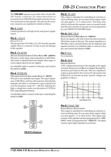
<strong>The</strong> <strong>VXR</strong>-<strong>9000</strong> repeater is provided with a 25-pin DB-<br />
25F female connector for interconnections to<br />
accessories.Use a DB-25M 25-pin male connector to connect<br />
accessories to the repeater. <strong>The</strong> pins on the accessory<br />
connector are explained in detail as follows:<br />
Pin 1: GND<br />
Chassis ground for all logic levels and power supply<br />
return.<br />
Pin 2: +13.6 V<br />
[POWER SUPPLY]<br />
This pin provides 13.6 Volts, 2.0 A, DC from the repeater<br />
supply. <strong>The</strong>re is a internal 3 A fuse to prevent damage<br />
to the repeater.<br />
Pin 3: TX AF IN<br />
[ANALOG TRANSMITTER INPUT] (VOICE BAND: 300 ~ 3,000 HZ)<br />
This pin is audio input. Input impedance is 600 Ohms.<br />
This audio is injected before the splatter filter stage, so<br />
excess signal input levels are clipped.<br />
Use shielded cable to connect to this pin, and connect<br />
the shield to GND.<br />
Pin 4: TONE IN<br />
[TRANSMITTER INPUT] (SUB-AUDIBLE BAND: 5 ~ 250 HZ)<br />
This pin is sub-audiable tone input. <strong>The</strong> input impedance<br />
is 600 Ohms, and has a flat response characteristic<br />
(repeater deviation is constant for a given signal level<br />
over the frequency range of 5 ~ 250 Hz). Injecting too<br />
high a voltage here causes over-deviation of CTCSS or<br />
DCS, degrading performance.<br />
Use shielded cable to connect to this pin, connecting the<br />
shield to GND.<br />
Pin 5: TX ATT<br />
This output is intended for controlling an external coaxial<br />
switching relay. It is an open drain output which<br />
can sink approx. 1.5 A when active. <strong>The</strong> delay time<br />
which is between the repeater cause to transmit mode<br />
and this port switches to ground can be programmed<br />
by your VERTEX STANDARD dealer.<br />
Pin 6: DISC OUT<br />
[ANALOG OUTPUT] (WIDE-BAND: 0 ~ 3,000 HZ)<br />
Received signals with full system deviation produce<br />
350 mVrms audio at this pin. <strong>The</strong> output impedance is<br />
600 Ohm, and is extracted before the de-emphasis and<br />
squelch circuitry. Use shielded cable to connect to this<br />
pin, and connect the shield to GND.<br />
Pin 7: N.C.<br />
No connection.<br />
Pin 8: RSSI<br />
[ANALOG OUTPUT]<br />
A DC voltage proportional to the strength of the signal<br />
currently being received (Receiver Signal Strength Indicator)<br />
is provided on this pin. This low impedance<br />
output is generated by the receiver IF sub-system and<br />
buffered by an internal op-amp. Typical voltages are<br />
graphed as follows:<br />
(DC V)<br />
RSSI Output Voltage<br />
2.5<br />
2.0<br />
1.5<br />
1.0<br />
0.5<br />
0<br />
–60 –70 –80 –90 –100 –110 –120 (dBm)<br />
Input Signal Level<br />
Pin 9: COAX. SW<br />
[LOGIC OUTPUT (ACTIVE LOW)]<br />
This output is intended for controlling an external coaxial<br />
switching relay. It is an open drain output which<br />
can sink approx. 1.5 A when active. This signal only<br />
switches if the repeater has been programmed for “SIM-<br />
PLEX” mode. If programmed for “DUPLEX,” the signal<br />
remains open (high impedance) at all time.<br />
DB-25 PIN NUMBERING<br />
<strong>VXR</strong>-<strong>9000</strong> FM REPEATER OPERATING MANUAL<br />
7


