Installation Guide: SwitchBlade x3112 (Rev. E) [PDF ... - Allied Telesis
Installation Guide: SwitchBlade x3112 (Rev. E) [PDF ... - Allied Telesis
Installation Guide: SwitchBlade x3112 (Rev. E) [PDF ... - Allied Telesis

You also want an ePaper? Increase the reach of your titles
YUMPU automatically turns print PDFs into web optimized ePapers that Google loves.
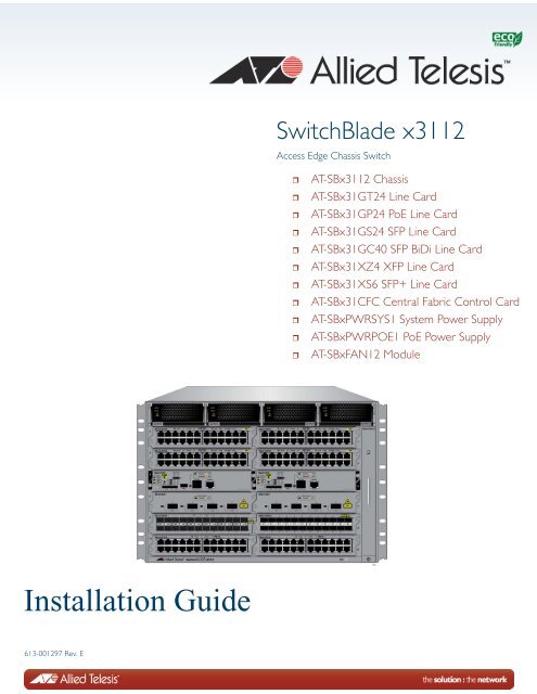
<strong>SwitchBlade</strong> <strong>x3112</strong><br />
Access Edge Chassis Switch<br />
<br />
<br />
<br />
<br />
<br />
<br />
<br />
<br />
<br />
<br />
<br />
AT-SB<strong>x3112</strong> Chassis<br />
AT-SBx31GT24 Line Card<br />
AT-SBx31GP24 PoE Line Card<br />
AT-SBx31GS24 SFP Line Card<br />
AT-SBx31GC40 SFP BiDi Line Card<br />
AT-SBx31XZ4 XFP Line Card<br />
AT-SBx31XS6 SFP+ Line Card<br />
AT-SBx31CFC Central Fabric Control Card<br />
AT-SBxPWRSYS1 System Power Supply<br />
AT-SBxPWRPOE1 PoE Power Supply<br />
AT-SBxFAN12 Module<br />
<strong>Installation</strong> <strong>Guide</strong><br />
613-001297 <strong>Rev</strong>. E
Copyright 2012 <strong>Allied</strong> <strong>Telesis</strong>, Inc.<br />
All rights reserved. No part of this publication may be reproduced without prior written permission from <strong>Allied</strong> <strong>Telesis</strong>,<br />
Inc.<br />
<strong>Allied</strong> <strong>Telesis</strong> and the <strong>Allied</strong> <strong>Telesis</strong> logo are trademarks of <strong>Allied</strong> <strong>Telesis</strong>, Incorporated. All other product names,<br />
company names, logos or other designations mentioned herein are trademarks or registered trademarks of their respective<br />
owners.<br />
<strong>Allied</strong> <strong>Telesis</strong>, Inc. reserves the right to make changes in specifications and other information contained in this document<br />
without prior written notice. The information provided herein is subject to change without notice. In no event shall <strong>Allied</strong><br />
<strong>Telesis</strong>, Inc. be liable for any incidental, special, indirect, or consequential damages whatsoever, including but not limited<br />
to lost profits, arising out of or related to this manual or the information contained herein, even if <strong>Allied</strong> <strong>Telesis</strong>, Inc. has<br />
been advised of, known, or should have known, the possibility of such damages.
Electrical Safety and Emissions Standards<br />
This product meets the following standards.<br />
Radiated Energy<br />
U.S. Federal Communications Commission<br />
Note: This equipment has been tested and found to comply with the limits for a Class A digital device pursuant to Part 15<br />
of FCC Rules. These limits are designed to provide reasonable protection against harmful interference when the<br />
equipment is operated in a commercial environment. This equipment generates, uses, and can radiate radio frequency<br />
energy and, if not installed and used in accordance with this instruction manual, may cause harmful interference to radio<br />
communications. Operation of this equipment in a residential area is likely to cause harmful interference in which case<br />
the user will be required to correct the interference at his own expense.<br />
Note: Modifications or changes not expressly approved of by the manufacturer or the FCC, can void your right to operate<br />
this equipment.<br />
Industry Canada<br />
This Class A digital apparatus complies with Canadian ICES-003.<br />
Cet appareil numérique de la classe A est conforme à la norme NMB-003 du Canada.<br />
European Union Restriction of the Use of Certain Hazardous Substances<br />
(RoHS) in Electrical and Electronic Equipment<br />
This <strong>Allied</strong> <strong>Telesis</strong> RoHS-compliant product conforms to the European Union Restriction of the Use of Certain Hazardous<br />
Substances (RoHS) in Electrical and Electronic Equipment. <strong>Allied</strong> <strong>Telesis</strong> ensures RoHS conformance by requiring<br />
supplier Declarations of Conformity, monitoring incoming materials, and maintaining manufacturing process controls.<br />
EMI/RFI Emissions: FCC Class A, EN55022 Class A, EN61000-3-2, EN61000-3-3, CISPR Class A,<br />
VCCI Class A, AS/NZS Class A<br />
Warning: In a domestic environment this product may cause radio interference in<br />
which case the user may be required to take adequate measures.<br />
Immunity: EN55024<br />
Electrical Safety: EN60950-1 (TUV), UL 60950-1 ( C UL US ), EN60825<br />
Safety Agency Approvals: C UL US , TUV, C-TICK, CE<br />
Laser Safety<br />
EN60825<br />
3
Translated Safety Statements<br />
Important: The indicates that a translation of the safety statement is available in a <strong>PDF</strong><br />
document titled “Translated Safety Statements” on our web site at<br />
http://www.alliedtelesis.com/support.<br />
4
Contents<br />
Preface ............................................................................................................................................................15<br />
Safety Symbols Used in this Document ...........................................................................................................16<br />
Contacting <strong>Allied</strong> <strong>Telesis</strong> ..................................................................................................................................17<br />
Chapter 1: Overview ......................................................................................................................................19<br />
Introduction.......................................................................................................................................................20<br />
AT-SB<strong>x3112</strong> Chassis .......................................................................................................................................23<br />
Ethernet Line and Control Cards Slots.......................................................................................................25<br />
Power Supply Slots....................................................................................................................................25<br />
AT-SBx31GT24 Line Card................................................................................................................................27<br />
AT-SBx31GP24 PoE Line Card........................................................................................................................28<br />
AT-SBx31GS24 SFP Line Card .......................................................................................................................29<br />
AT-SBx31GC40 Line Card ...............................................................................................................................30<br />
AT-SBx31XZ4 XFP Line Card ..........................................................................................................................32<br />
AT-SBx31XS6 SFP+ Line Card........................................................................................................................33<br />
10/100/1000Base-T Twisted Pair Ports............................................................................................................34<br />
Connector Type..........................................................................................................................................34<br />
Speed.........................................................................................................................................................34<br />
Duplex Mode..............................................................................................................................................34<br />
Maximum Distance.....................................................................................................................................34<br />
Cable Requirements ..................................................................................................................................35<br />
Automatic MDIX Detection.........................................................................................................................36<br />
Straight-through or Crossover Cabling.......................................................................................................36<br />
Port Pinouts................................................................................................................................................37<br />
Power over Ethernet on the AT-SBx31GP24 Line Card...................................................................................38<br />
Powered Device Classes ...........................................................................................................................38<br />
Power Budgeting........................................................................................................................................39<br />
PoE Wiring .................................................................................................................................................39<br />
Port Numbers on the AT-SBx31GC40 Line Card .............................................................................................41<br />
Port LEDs on the Ethernet Line Cards .............................................................................................................43<br />
AT-SBx31GT24 Line Card .........................................................................................................................43<br />
AT-SBx31GP24 Line Card.........................................................................................................................44<br />
AT-SBx31GS24 Line Card.........................................................................................................................45<br />
AT-SBx31GC40 Line Card.........................................................................................................................46<br />
AT-SBx31XZ4 Line Card............................................................................................................................48<br />
AT-SBx31XS6 Line Card ...........................................................................................................................49<br />
AT-SBx31CFC Central Fabric Controller Card.................................................................................................50<br />
SYS Status LEDs.......................................................................................................................................51<br />
SBx STATUS LEDs....................................................................................................................................52<br />
eco-friendly Button .....................................................................................................................................53<br />
Reset Button ..............................................................................................................................................53<br />
NET MGMT Port ........................................................................................................................................55<br />
NET MGMT LED........................................................................................................................................57<br />
Console (RS-232) Port...............................................................................................................................57<br />
SD Card Slot ..............................................................................................................................................57<br />
5
Contents<br />
SD Status LED .......................................................................................................................................... 58<br />
USB Port.................................................................................................................................................... 58<br />
Power Supplies ................................................................................................................................................ 59<br />
LEDs.......................................................................................................................................................... 60<br />
AT-SBxFAN12 Module..................................................................................................................................... 62<br />
LED............................................................................................................................................................ 62<br />
Power Supply Interfaces (Opto-couplers) ........................................................................................................ 63<br />
LED............................................................................................................................................................ 63<br />
Module Names in the Management Software.................................................................................................. 64<br />
Management Software Releases for the Hardware Components.................................................................... 65<br />
Chapter 2: Safety Precautions and Site Preparation ................................................................................. 67<br />
<strong>Rev</strong>iewing Safety Precautions ......................................................................................................................... 68<br />
Selecting a Site for the <strong>SwitchBlade</strong> <strong>x3112</strong> ..................................................................................................... 72<br />
Chapter 3: Installing the Chassis in an Equipment Rack .......................................................................... 75<br />
Required Tools and Material............................................................................................................................ 76<br />
Preparing the Equipment Rack ........................................................................................................................ 77<br />
Unpacking the AT-SB<strong>x3112</strong> Chassis............................................................................................................... 80<br />
Adjusting the Equipment Rack Brackets.......................................................................................................... 82<br />
Installing the AT-SB<strong>x3112</strong> Chassis in the Equipment Rack............................................................................. 84<br />
Removing the Shipping Brace ......................................................................................................................... 87<br />
Installing the Chassis Grounding Lug .............................................................................................................. 88<br />
Chapter 4: Installing the Power Supplies ................................................................................................... 91<br />
Protecting Against Electrostatic Discharge (ESD) ........................................................................................... 92<br />
Installing the AT-SBxPWRSYS1 AC System Power Supply............................................................................ 93<br />
Installing the AT-SBxPWRPOE1 AC Power Supply ........................................................................................ 99<br />
Installing the AT-SBxPWRSYS1 DC Power Supply....................................................................................... 105<br />
Chapter 5: Installing the AT-SBx31CFC Card and Ethernet Line Cards ................................................ 111<br />
Installing the AT-SBx31CFC Central Fabric Controller Card ......................................................................... 112<br />
Installing the Ethernet Line Cards.................................................................................................................. 118<br />
Installing the Blank Slot Covers ..................................................................................................................... 122<br />
Chapter 6: Installing the Transceivers and Cabling the Ports ................................................................ 125<br />
<strong>Guide</strong>lines to Cabling the Twisted Pair Ports on the AT-SBx31GP24 and AT-SBx31GT24 Line Cards ....... 126<br />
<strong>Guide</strong>lines to Installing SFP, SFP+, CSFP, and XFP Transceivers............................................................... 128<br />
Installing SFP Transceivers in the AT-SBx31GS24 Line Card ...................................................................... 129<br />
Installing SFP and CSFP Transceivers in the AT-SBx31GC40 Line Card..................................................... 133<br />
Installing SFP+ Transceivers in the AT-SBx31XS6 Line Card.......................................................................137<br />
Installing AT-SP10TW Cables in the AT-SBx31XS6 Line Card..................................................................... 141<br />
Installing XFP Transceivers in the AT-SBx31XZ4 Line Card......................................................................... 144<br />
Cabling the NET MGMT Port on the AT-SBx31CFC Card............................................................................. 148<br />
Chapter 7: Powering On the Chassis ........................................................................................................ 151<br />
Verifying the <strong>Installation</strong>................................................................................................................................. 152<br />
Powering On the AT-SBxPWRSYS1 AC Power Supply ................................................................................ 153<br />
Powering on the AT-SBxPWRPOE1 AC Power Supply................................................................................. 156<br />
Powering On the AT-SBxPWRSYS1 DC System Power Supply................................................................... 159<br />
Choosing a Method for Attaching the Grounding Wire ............................................................................ 161<br />
Connecting the Grounding Wire with the Grounding Terminal ................................................................ 161<br />
Connecting the Grounding Wire with Bare Wire...................................................................................... 164<br />
Choosing a Method for Attaching the Power Wires.................................................................................165<br />
Connecting the DC Power Wires with the Straight Terminals ................................................................. 166<br />
Connecting the DC Power Wires with the Right Angle Terminals ........................................................... 173<br />
Connecting Bare DC Power Wires .......................................................................................................... 178<br />
6
<strong>SwitchBlade</strong> <strong>x3112</strong> <strong>Installation</strong> <strong>Guide</strong><br />
Monitoring the Initialization Process ...............................................................................................................182<br />
Using the LEDs to Monitor the Initialization Process ...............................................................................183<br />
Using the Console Port to Monitor the Initialization Process ...................................................................184<br />
Chapter 8: Verifying the Hardware Operations of the Chassis ...............................................................187<br />
Using the LEDs to Verify the Chassis.............................................................................................................188<br />
Using Local Management to Verify the Chassis.............................................................................................190<br />
Starting a Local Management Session ....................................................................................................190<br />
Entering the Management Software Commands .....................................................................................191<br />
Chapter 9: Troubleshooting .......................................................................................................................195<br />
AT-SBxPWRSYS1 and AT-SBxPWRPOE1 AC Power Supplies ...................................................................196<br />
AT-SBxPWRSYS1 DC Power Supply ............................................................................................................197<br />
Ethernet Line Cards........................................................................................................................................199<br />
Twisted Pair Ports ..........................................................................................................................................201<br />
Power Over Ethernet ......................................................................................................................................203<br />
Fiber Optic Transceivers ................................................................................................................................205<br />
AT-SBx31CFC Central Fabric Controller Card...............................................................................................207<br />
AT-SBxFAN12 Fan Module ............................................................................................................................208<br />
Local (Out-of-Band) Management Session ....................................................................................................209<br />
Power Supply Interfaces (Opto-couplers).......................................................................................................210<br />
Appendix A: Technical Specifications ......................................................................................................211<br />
Physical Specifications ...................................................................................................................................211<br />
Environmental Specifications .........................................................................................................................213<br />
Power Specifications ......................................................................................................................................214<br />
Safety and Electromagnetic Emissions Certifications ....................................................................................217<br />
Connectors and Port Pinouts..........................................................................................................................218<br />
7
Contents<br />
8
Figures<br />
Figure 1: AT-SB<strong>x3112</strong> Chassis ....................................................................................................................... 20<br />
Figure 2: Ethernet Line Cards and AT-SBx31CFC Central Fabric Controller Card......................................... 20<br />
Figure 3: Ethernet Line Cards and AT-SBx31CFC Central Fabric Controller Card (Continued)..................... 21<br />
Figure 4: Power Supply Units .......................................................................................................................... 21<br />
Figure 5: Fan Module ...................................................................................................................................... 22<br />
Figure 6: Front View of the AT-SB<strong>x3112</strong> Chassis ........................................................................................... 23<br />
Figure 7: Rear View of the AT-SB<strong>x3112</strong> Chassis............................................................................................ 24<br />
Figure 8: AT-SB<strong>x3112</strong> Chassis with Line Cards, Control Cards, and Power Supplies ................................... 24<br />
Figure 9: Slots for the Ethernet Line and Control Cards.................................................................................. 25<br />
Figure 10: Power Supply Slots ........................................................................................................................ 25<br />
Figure 11: AT-SBx31GT24 Line Card ............................................................................................................. 27<br />
Figure 12: AT-SBx31GP24 PoE Line Card ..................................................................................................... 28<br />
Figure 13: AT-SBx31GS24 SFP Line Card ..................................................................................................... 29<br />
Figure 14: AT-SBx31GC40 Line Card ............................................................................................................. 30<br />
Figure 15: AT-SBx31XZ4 XFP Line Card........................................................................................................ 32<br />
Figure 16: AT-SBx31XS6 Line Card................................................................................................................ 33<br />
Figure 17: Port Numbers for Slots with CSFP Transceivers ........................................................................... 41<br />
Figure 18: Port Numbers for Slots with Standard SFP Transceivers .............................................................. 42<br />
Figure 19: Port LEDs on the AT-SBx31GT24 Line Card ................................................................................. 43<br />
Figure 20: Port LEDs on the AT-SBx31GP24 PoE Line Card ......................................................................... 44<br />
Figure 21: Port LEDs on the AT-SBx31GS24 SFP Line Card......................................................................... 45<br />
Figure 22: LEDs for the AT-SBx31GC40 Line Card ........................................................................................ 46<br />
Figure 23: LEDs for the AT-SBx31GC40 Line Card, with CSFP Transceivers ............................................... 47<br />
Figure 24: LEDs for the AT-SBx31GC40 Line Card, with SFP Transceivers .................................................. 47<br />
Figure 25: Transceiver Slot LEDs on the AT-SBx31XZ4 XFP Line Card ........................................................ 48<br />
Figure 26: SFP+ Slot LEDs on the AT-SBx31XS6 Line Card.......................................................................... 49<br />
Figure 27: AT-SBx31CFC Central Fabric Controller Card............................................................................... 51<br />
Figure 28: AT-SBxFAN12 Module ................................................................................................................... 62<br />
Figure 29: Power Supply Interfaces (Opto-couplers) ...................................................................................... 63<br />
Figure 30: 100 - 125 VAC 125 V NEMA 5-20 Plug and Receptacle................................................................ 73<br />
Figure 31: Reserving Vertical Rack Space...................................................................................................... 78<br />
Figure 32: Rack Mounting Hole Locations....................................................................................................... 79<br />
Figure 33: AT-SB<strong>x3112</strong> Chassis Items ........................................................................................................... 80<br />
Figure 34: AT-SB<strong>x3112</strong> Chassis Items (Continued)........................................................................................ 81<br />
Figure 35: Rack Mounting Bracket Locations.................................................................................................. 83<br />
Figure 36: Rack Bracket Locations for <strong>Rev</strong>erse Position of Chassis .............................................................. 83<br />
Figure 37: Lifting the AT-SB<strong>x3112</strong> Chassis into the Equipment Rack ............................................................ 85<br />
Figure 38: Installing the Rack Mount Screws .................................................................................................. 86<br />
Figure 39: Removing the Shipping Brace........................................................................................................ 87<br />
Figure 40: Stripping the Grounding Wire ......................................................................................................... 88<br />
Figure 41: Removing the Grounding Lug ........................................................................................................ 88<br />
Figure 42: Attaching the Grounding Wire to the Grounding Lug ..................................................................... 89<br />
Figure 43: Installing the Grounding Lug and Wire ........................................................................................... 89<br />
Figure 44: ESD Socket .................................................................................................................................... 92<br />
Figure 45: Power Supply Slots ........................................................................................................................ 93<br />
9
List of Figures<br />
Figure 46: Removing the Blank Slot Cover from Power Supply Slot C............................................................ 94<br />
Figure 47: Items Included with the AT-SBxPWRSYS1 Power Supply Module ................................................ 95<br />
Figure 48: Verifying the AT-SBxPWRSYS1 AC Power Supply........................................................................ 96<br />
Figure 49: Raising the Handle on the AT-SBxPWRSYS1 AC Power Supply .................................................. 96<br />
Figure 50: Inserting the AT-SBxPWRSYS1 AC Power Supply........................................................................ 97<br />
Figure 51: Lowering the Handle on the AT-SBxPWRSYS1 AC Power Supply................................................ 98<br />
Figure 52: Power Supply Slots......................................................................................................................... 99<br />
Figure 53: Removing the Blank Slot Cover from Power Supply Slot A.......................................................... 100<br />
Figure 54: Items Included with the AT-SBxPWRPOE1 Power Supply Module.............................................. 101<br />
Figure 55: Verifying the AT-SBxPWRPOE1 AC Power Supply ..................................................................... 102<br />
Figure 56: Raising the Handle on the AT-SBxPWRPOE1 AC Power Supply................................................ 102<br />
Figure 57: Inserting the AT-SBxPWRPOE1 AC Power Supply...................................................................... 103<br />
Figure 58: Locking the Handle on the AT-SBxPWRPOE1 AC Power Supply................................................ 104<br />
Figure 59: Power Supply Slots....................................................................................................................... 105<br />
Figure 60: Removing the Blank Slot Cover from Power Supply Slot C.......................................................... 106<br />
Figure 61: Items Included with the AT-SBxPWRSYS1 DC Power Supply Module........................................ 107<br />
Figure 62: Loosening the Handle locking Screw on the AT-SBxPWRPOE1 DC Power Supply.................... 108<br />
Figure 63: Raising the Handle on the AT-SBxPWRPOE1 DC Power Supply................................................ 108<br />
Figure 64: Inserting the AT-SBxPWRSYS1 DC Power Supply...................................................................... 109<br />
Figure 65: Locking the Handle on the AT-SBxPWRSYS1 Power Supply...................................................... 110<br />
Figure 66: Slots 4 and 5 for the AT-SBx31CFC Card .................................................................................... 112<br />
Figure 67: Items Included with the AT-SBx31CFC Central Fabric Controller Card ....................................... 113<br />
Figure 68: Opening the Locking Handles on the AT-SBx31CFC Central Fabric Controller Card.................. 113<br />
Figure 69: Removing the Battery Insulator .................................................................................................... 114<br />
Figure 70: Aligning the AT-SBx31CFC Card in the Chassis Slot................................................................... 114<br />
Figure 71: Inserting the AT-SBx31CFC Card in the Chassis Slot.................................................................. 115<br />
Figure 72: Closing the Locking Levers on the AT-SBx31CFC Central Fabric Controller Card...................... 116<br />
Figure 73: Tightening the Thumb Screws on the AT-SBx31CFC Card.......................................................... 117<br />
Figure 74: Slots 0 to 3 and 6 to 11 for the Ethernet Line Cards..................................................................... 118<br />
Figure 75: Aligning an Ethernet Line Card in a Chassis Slot ......................................................................... 119<br />
Figure 76: Inserting an Ethernet Line Card.................................................................................................... 120<br />
Figure 77: Tightening the Thumb Screws on an Ethernet Line Card............................................................. 121<br />
Figure 78: Installing a Blank Slot Cover......................................................................................................... 122<br />
Figure 79: Tightening the Thumbscrews on a Blank Slot Cover.................................................................... 123<br />
Figure 80: Removing the Dust Cover from an SFP Slot in the AT-SBx31GS24 Line Card ........................... 129<br />
Figure 81: Handle on SFP Transceiver.......................................................................................................... 130<br />
Figure 82: Inserting the SFP Transceiver in the AT-SBx31GS24 Line Card ................................................. 130<br />
Figure 83: Removing the Dust Cover from the SFP Transceiver in the AT-SBx31GS24 Line Card.............. 131<br />
Figure 84: Attaching a Fiber Optic Cable to an SFP Transceiver in the AT-SBx31GS24 Line Card ............. 132<br />
Figure 85: Removing the Dust Cover from a Transceiver Slot....................................................................... 133<br />
Figure 86: Labels on SFP and CSFP Transceivers ....................................................................................... 134<br />
Figure 87: Inserting an SFP or a CSFP Transceiver...................................................................................... 134<br />
Figure 88: Removing the Dust Cover from an SFP or a CSFP Transceiver.................................................. 135<br />
Figure 89: Attaching a Fiber Optic Cable....................................................................................................... 136<br />
Figure 90: Removing a Dust Cover From an SFP+ Slot in the AT-SBx31XS6 Line Card ............................. 137<br />
Figure 91: Handle on SFP+ Transceiver........................................................................................................ 138<br />
Figure 92: Installing an SFP+ Transceiver in the AT-SBx31XS6 Line Card .................................................. 138<br />
Figure 93: Removing the Dust Cover from an SFP+ Transceiver in the AT-SBx31XS6 Line Card ............... 139<br />
Figure 94: Attaching a Fiber Optic Cable to an SFP+ Transceiver in the AT-SBx31XS6 Line Card ............. 140<br />
Figure 95: Removing the Dust Cover From an SFP+ Slot in the AT-SBx31XS6 Line Card .......................... 141<br />
Figure 96: Release Tab on the AT-SBx31XS6 Line Card.............................................................................. 142<br />
Figure 97: Installing the AT-SP10TW Cable in the AT-SBx31XS6 Line Card................................................ 142<br />
Figure 98: Removing the Dust Cover From an XFP Slot on the AT-SBx31XZ4 Line Card............................ 144<br />
Figure 99: Handle on the XFP Transceiver.................................................................................................... 145<br />
Figure 100: Installing an XFP Transceiver in the AT-SBx31XZ4 Line Card................................................... 145<br />
10
<strong>SwitchBlade</strong> <strong>x3112</strong> <strong>Installation</strong> <strong>Guide</strong><br />
Figure 101: Removing the Protective Cover from an XFP Transceiver in the AT-SBx31XZ4 Line Card ...... 146<br />
Figure 102: Attaching a Fiber Optic Cable to an XFP Transceiver in the AT-SBx31XZ4 Line Card ............. 147<br />
Figure 103: AC Sockets on the AT-SB<strong>x3112</strong> Chassis Rear Panel ............................................................... 153<br />
Figure 104: Connecting the AC Power Cord for the AT-SBxPWRSYS1 Power Supply................................ 154<br />
Figure 105: Securing the Power Cord for the AT-SBxPWRSYS1 Power Supply to an Anchor .................... 155<br />
Figure 106: Connecting the AC Power Cord for the AT-SBxPWRPOE1 Power Supply ............................... 156<br />
Figure 107: Securing the Power Cord for the AT-SBxPWRPOE1 Power Supply to an Anchor .................... 157<br />
Figure 108: Dress and Secure AC Power Cords........................................................................................... 158<br />
Figure 109: Components of the AT-SBxPWRSYS1 DC Power Supply......................................................... 160<br />
Figure 110: Grounding Wire Terminal ........................................................................................................... 161<br />
Figure 111: Stripping the Stranded Grounding Wire ..................................................................................... 161<br />
Figure 112: Attaching the Stranded Grounding Wire to the Grounding Terminal.......................................... 161<br />
Figure 113: Removing the Nut and Washer from the Grounding Post .......................................................... 162<br />
Figure 114: Installing the Grounding Wire ..................................................................................................... 163<br />
Figure 115: Stripping the solid or Stranded Grounding Wire......................................................................... 164<br />
Figure 116: Attaching the Bare Grounding Wire to the Grounding Post........................................................ 164<br />
Figure 117: Securing the Bare Grounding Wire to the Grounding Post ........................................................ 165<br />
Figure 118: Power Wire Terminals ................................................................................................................ 165<br />
Figure 119: Stripping the Power Wires.......................................................................................................... 166<br />
Figure 120: Attaching the Power Wires to the Power Terminal Lugs ............................................................ 167<br />
Figure 121: Opening the Plastic Cover.......................................................................................................... 167<br />
Figure 122: Removing the Terminal Screws ................................................................................................. 168<br />
Figure 123: Connecting the Power Wires...................................................................................................... 169<br />
Figure 124: Closing the Plastic Cover over the Terminal Connectors........................................................... 170<br />
Figure 125: Tightening the Handle Locking Screw........................................................................................ 171<br />
Figure 126: Turning On the Power Supply .................................................................................................... 172<br />
Figure 127: Stripping the Power Wires.......................................................................................................... 173<br />
Figure 128: Attaching the Power Wires to the Right Angle Terminals........................................................... 173<br />
Figure 129: Removing the Plastic Cover ....................................................................................................... 174<br />
Figure 130: Removing the Terminal Screws ................................................................................................. 175<br />
Figure 131: Connecting the Power Wires...................................................................................................... 176<br />
Figure 132: Tightening the Handle Locking Screw........................................................................................ 177<br />
Figure 133: Turning On the Power Supply .................................................................................................... 178<br />
Figure 134: Stripping Solid or Stranded DC Power Wires............................................................................. 178<br />
Figure 135: Connecting the Positive Wire ..................................................................................................... 179<br />
Figure 136: Connecting the Negative Lead Wire........................................................................................... 180<br />
Figure 137: Switch Initialization Messages.................................................................................................... 184<br />
Figure 138: Switch Initialization Messages (Continued)................................................................................ 185<br />
Figure 139: Connecting the Management Cable to the Console RS-232 Port.............................................. 190<br />
Figure 140: SHOW SYSTEM Command....................................................................................................... 191<br />
Figure 141: SHOW PSU Command .............................................................................................................. 192<br />
Figure 142: SHOW FANMODULE Command ............................................................................................... 193<br />
Figure 143: SHOW CARD Command ........................................................................................................... 193<br />
Figure 144: RJ-45 Connector and Port Pin Layout........................................................................................ 218<br />
11
List of Figures<br />
12
Tables<br />
Table 1. Twisted Pair Cable for the AT-SBx31GT24 Line Card ..................................................................... 35<br />
Table 2. Twisted Pair Cable for the AT-SBx31GP24 Line Card ..................................................................... 35<br />
Table 3. IEEE802.3af and IEEE802.3at Powered Device Classes ................................................................ 38<br />
Table 4. Maximum Number of Powered Devices ........................................................................................... 39<br />
Table 5. Port LEDs on the AT-SBx31GT24 Line Card ................................................................................... 43<br />
Table 6. Port LEDs on the AT-SBx31GP24 PoE Line Card ........................................................................... 44<br />
Table 7. Port LEDs on the AT-SBx31GS24 SFP Line Card ........................................................................... 45<br />
Table 8. Transceiver Slot LEDs on the AT-SBx31GC40 Line Card ............................................................... 48<br />
Table 9. Transceiver Slot LEDs on the AT-SBx31XZ4 XFP Line Card .......................................................... 48<br />
Table 10. SFP+ Slot LEDs on the AT-SBx31XS6 Line Card .......................................................................... 49<br />
Table 11. SYS (System) Status LEDs ............................................................................................................ 51<br />
Table 12. SBx STATUS LEDs ........................................................................................................................ 52<br />
Table 13. Features that Use the NET MGMT Port ......................................................................................... 55<br />
Table 14. NET MGMT Port LED ..................................................................................................................... 57<br />
Table 15. SD Status LED ............................................................................................................................... 58<br />
Table 16. LEDs on the AT-SBxPWRSYS1 AC Power Supply ........................................................................ 60<br />
Table 17. LEDs on the AT-SBxPWRSYS1 DC Power Supply ....................................................................... 61<br />
Table 18. LEDs on the AT-SBxPWRPOE1 AC Power Supply ....................................................................... 61<br />
Table 19. AT-SBxFAN12 Module LED ........................................................................................................... 62<br />
Table 20. Power Supply Interface LED .......................................................................................................... 63<br />
Table 21. Card Types in the Management Software ...................................................................................... 64<br />
Table 22. Management Software Releases for the Hardware Components .................................................. 65<br />
Table 23. Front Panel to Rack Rail Dimensions ............................................................................................. 82<br />
Table 24. Switch Initialization Phases .......................................................................................................... 183<br />
Table 25. Product Dimensions ..................................................................................................................... 211<br />
Table 26. Product Weights ........................................................................................................................... 211<br />
Table 27. Environmental Specifications ....................................................................................................... 213<br />
Table 28. Acoustic Noise Test Components ................................................................................................ 213<br />
Table 29. AC Voltage and Frequency Requirements ................................................................................... 214<br />
Table 30. DC Voltage Requirement .............................................................................................................. 214<br />
Table 31. Typical Power Savings in eco-friendly Mode ................................................................................ 214<br />
Table 32. Maximum Power Consumption ..................................................................................................... 214<br />
Table 33. Maximum Power Efficiency .......................................................................................................... 215<br />
Table 34. Heat Dissipation ........................................................................................................................... 215<br />
Table 35. Available Power Over Ethernet with One PoE Power Supply ...................................................... 216<br />
Table 36. Available Power Over Ethernet with Two PoE Power Supplies ................................................... 216<br />
Table 37. PoE Mode ..................................................................................................................................... 216<br />
Table 38. Safety and Electromagnetic Emissions ........................................................................................ 217<br />
Table 39. Quality and Reliability ................................................................................................................... 217<br />
Table 40. MDI Pin Signals (10Base-T or 100Base-TX) ................................................................................ 218<br />
Table 41. MDI-X Pin Signals (10Base-T or 100Base-TX) ............................................................................ 218<br />
Table 42. RJ-45 1000Base-T Connector Pinouts ......................................................................................... 219<br />
13
List of Tables<br />
14
Preface<br />
This guide contains the hardware installation instructions for the<br />
<strong>SwitchBlade</strong> <strong>x3112</strong> switch. This preface contains the following sections:<br />
“Safety Symbols Used in this Document” on page 16<br />
“Contacting <strong>Allied</strong> <strong>Telesis</strong>” on page 17<br />
Note<br />
This version of the installation guide applies to release 16.0 of the<br />
<strong>SwitchBlade</strong> <strong>x3112</strong> Management Software. The latest release of the<br />
management software is available from the Restricted Software<br />
Downloads web page on the <strong>Allied</strong> <strong>Telesis</strong> web site, at<br />
www.alliedtelesis.com/support/software/restricted.<br />
15
Preface<br />
Safety Symbols Used in this Document<br />
This document uses the following conventions.<br />
Note<br />
Notes provide additional information.<br />
Caution<br />
Cautions inform you that performing or omitting a specific action<br />
may result in equipment damage or loss of data.<br />
Warning<br />
Warnings inform you that performing or omitting a specific action<br />
may result in bodily injury.<br />
Warning<br />
Laser warnings inform you that an eye or skin hazard exists due to<br />
the presence of a Class 1 laser device.<br />
16
<strong>SwitchBlade</strong> <strong>x3112</strong> <strong>Installation</strong> <strong>Guide</strong><br />
Contacting <strong>Allied</strong> <strong>Telesis</strong><br />
If you need assistance with this product, you may contact <strong>Allied</strong> <strong>Telesis</strong><br />
technical support by going to the Support & Services section of the <strong>Allied</strong><br />
<strong>Telesis</strong> web site at www.alliedtelesis.com/support. You can find links for<br />
the following services on this page:<br />
<br />
<br />
<br />
<br />
<br />
<br />
24/7 Online Support — Enter our interactive support center to<br />
search for answers to your product questions in our knowledge<br />
database, to check support tickets, to learn about RMAs, and to<br />
contact <strong>Allied</strong> <strong>Telesis</strong> technical experts.<br />
USA and EMEA phone support — Select the phone number that<br />
best fits your location and customer type.<br />
Hardware warranty information — Learn about <strong>Allied</strong> <strong>Telesis</strong><br />
warranties and register your product online.<br />
Replacement Services — Submit a Return Merchandise<br />
Authorization (RMA) request via our interactive support center.<br />
Documentation — View the most recent installation and user<br />
guides, software release notes, white papers, and data sheets for<br />
your products.<br />
Software Downloads — Download the latest software releases for<br />
your managed products.<br />
For sales or corporate information, go to www.alliedtelesis.com/<br />
purchase and select your region.<br />
17
Preface<br />
18
Chapter 1<br />
Overview<br />
This chapter describes the <strong>SwitchBlade</strong> <strong>x3112</strong> product in the following<br />
sections:<br />
“Introduction” on page 20<br />
“AT-SB<strong>x3112</strong> Chassis” on page 23<br />
“AT-SBx31GT24 Line Card” on page 27<br />
“AT-SBx31GP24 PoE Line Card” on page 28<br />
“AT-SBx31GS24 SFP Line Card” on page 29<br />
“AT-SBx31GC40 Line Card” on page 30<br />
“AT-SBx31XZ4 XFP Line Card” on page 32<br />
“AT-SBx31XS6 SFP+ Line Card” on page 33<br />
“10/100/1000Base-T Twisted Pair Ports” on page 34<br />
“Power over Ethernet on the AT-SBx31GP24 Line Card” on page 38<br />
“Port Numbers on the AT-SBx31GC40 Line Card” on page 41<br />
“Port LEDs on the Ethernet Line Cards” on page 43<br />
“AT-SBx31CFC Central Fabric Controller Card” on page 50<br />
“Power Supplies” on page 59<br />
“AT-SBxFAN12 Module” on page 62<br />
“Power Supply Interfaces (Opto-couplers)” on page 63<br />
“Module Names in the Management Software” on page 64<br />
“Management Software Releases for the Hardware Components” on<br />
page 65<br />
Note<br />
This version of the installation guide applies to release 16.0 of the<br />
<strong>SwitchBlade</strong> <strong>x3112</strong> Management Software. The latest release of the<br />
management software is available from the Restricted Software<br />
Downloads web page on the <strong>Allied</strong> <strong>Telesis</strong> web site, at<br />
www.alliedtelesis.com/support/software/restricted.<br />
19
Chapter 1: Overview<br />
Introduction<br />
The <strong>SwitchBlade</strong> <strong>x3112</strong> product is a modular Gigabit and 10 Gigabit<br />
Ethernet switch. The main components are the AT-SB<strong>x3112</strong> Chassis, six<br />
Ethernet line cards, a control card, a system power supply, a Power over<br />
Ethernet Plus (PoE+) power supply, and a fan module. The AT-SB<strong>x3112</strong><br />
Chassis is shown in Figure 1.<br />
Slots for ten Ethernet line cards, two control<br />
cards, two system power supplies, and two<br />
Power over Ethernet Plus (PoE+) power<br />
supplies.<br />
Figure 1. AT-SB<strong>x3112</strong> Chassis<br />
The Ethernet line cards and AT-SBx31CFC Central Fabric Controller card<br />
are shown in Figure 2 here and Figure 3 on page 21.<br />
AT-SBx31GT24 Ethernet Line Card with 24<br />
10/100/1000Base-T twisted pair ports.<br />
AT-SBx31GP24 Ethernet Line Card with 24<br />
10/100/1000Base-T twisted pair ports, with<br />
PoE+.<br />
AT-SBx31GS24 Ethernet Line Card with 24<br />
slots for 100 or 1000Mbps, fiber optic or<br />
twisted pair SFP transceivers.<br />
AT-SBx31GC40 Ethernet Line Card with 20<br />
slots for 1000Mbps standard SFP or<br />
compact SFP (CSFP) BiDi transceivers.<br />
Figure 2. Ethernet Line Cards and AT-SBx31CFC Central Fabric<br />
Controller Card<br />
20
<strong>SwitchBlade</strong> <strong>x3112</strong> <strong>Installation</strong> <strong>Guide</strong><br />
AT-SBx31XZ4 Ethernet Line Card with four<br />
slots for 10Gbps, fiber optic XFP<br />
transceivers.<br />
AT-SBx31XS6 Ethernet Line Card with six<br />
slots for 10Gbps, fiber optic SFP+<br />
transceivers or Twinax direct connect<br />
cables.<br />
AT-SBx31CFC Central Fabric Controller<br />
card<br />
Figure 3. Ethernet Line Cards and AT-SBx31CFC Central Fabric<br />
Controller Card (Continued)<br />
The three power supplies are shown in Figure 4.<br />
AT-SBxPWRSYS1 AC Power Supply for the<br />
Ethernet line cards, controller modules, and<br />
fan module.<br />
AT-SBxPWRPOE1 AC Power Supply with<br />
1200 W PoE budget for the ports on the AT-<br />
SBx31GP24 PoE Ethernet Line Card.<br />
AT-SBxPWRSYS1 DC Power Supply for the<br />
Ethernet line cards, controller modules, and<br />
fan module.<br />
Figure 4. Power Supply Units<br />
21
Chapter 1: Overview<br />
The fan module is shown in Figure 5.<br />
AT-SBxFAN12 Module, the cooling unit for<br />
the chassis<br />
Figure 5. Fan Module<br />
22
<strong>SwitchBlade</strong> <strong>x3112</strong> <strong>Installation</strong> <strong>Guide</strong><br />
AT-SB<strong>x3112</strong> Chassis<br />
The AT-SB<strong>x3112</strong> Chassis is a 7RU unit. It has slots for ten Ethernet line<br />
cards, two control cards, two system power supply modules, and two PoE<br />
power supply modules. The chassis components are identified in Figure 6<br />
here and Figure 7 on page 24.<br />
Figure 6. Front View of the AT-SB<strong>x3112</strong> Chassis<br />
Note<br />
Do not remove the shipping brace from the front of the chassis until<br />
after the unit is installed in the equipment rack. You might bend the<br />
chassis and cause misalignment of the slots and card guides if you<br />
lift the chassis into the equipment rack without the shipping brace.<br />
23
Chapter 1: Overview<br />
Figure 7. Rear View of the AT-SB<strong>x3112</strong> Chassis<br />
Figure 8 is an example of a fully populated chassis.<br />
Figure 8. AT-SB<strong>x3112</strong> Chassis with Line Cards, Control Cards, and Power<br />
Supplies<br />
24
<strong>SwitchBlade</strong> <strong>x3112</strong> <strong>Installation</strong> <strong>Guide</strong><br />
Ethernet Line<br />
and Control<br />
Cards Slots<br />
The chassis has slots for ten Ethernet line cards and two AT-SBx31CFC<br />
Central Fabric Controller cards. The slot definitions are predefined and<br />
may not be changed. Figure 9 identifies the slots, which are numbered<br />
starting with 0.<br />
Slot 0 - Line Card<br />
Slot 2 - Line Card<br />
Slot 4 - Control Card<br />
Slot 6 - Line Card<br />
Slot 8 - Line Card<br />
Slot 10 - Line Card<br />
Slot 1 - Line Card<br />
Slot 3 - Line Card<br />
Slot 5 - Control Card<br />
Slot 7 - Line Card<br />
Slot 9 - Line Card<br />
Slot 11 - Line Card<br />
Figure 9. Slots for the Ethernet Line and Control Cards<br />
Slots 0 to 3 and 6 to 11 are for the Ethernet line cards. The cards may be<br />
installed in any order or variety in the slots.<br />
Slots 4 and 5 are for the AT-SBx31CFC Central Fabric Controller card, of<br />
which there must be at least one in the chassis. You may add a second<br />
controller to add redundancy or to increase the available traffic bandwidth<br />
of the chassis.<br />
Power Supply<br />
Slots<br />
The chassis has four power supply slots, labelled A to D, across the top of<br />
the front of the chassis.<br />
Slot A<br />
AT-SBxPWRPOE1<br />
Power Supply<br />
Slot B<br />
AT-SBxPWRPOE1<br />
Power Supply<br />
Slot C<br />
AT-SBxPWRSYS1<br />
Power Supply<br />
Slot D<br />
AT-SBxPWRSYS1<br />
Power Supply<br />
Figure 10. Power Supply Slots<br />
25
Chapter 1: Overview<br />
The two right hand slots are for the AT-SBxPWRSYS1 Power Supply,<br />
which supplies power to the Ethernet line cards, control modules, and fan<br />
module. The only chassis component not powered by the module is the<br />
PoE feature on the twisted pair ports of the AT-SBx31GP24 PoE Line<br />
Card.<br />
There are AC and DC versions of the AT-SBxPWRSYS1 Power Supply.<br />
Refer to Figure 4 on page 21 for illustrations of the modules.<br />
A single AT-SBxPWRSYS1 Power Supply can support a fully populated<br />
chassis. However, you may install two power supplies to add power<br />
redundancy to the unit.<br />
The two left hand slots are for the AT-SBxPWRPOE1 Power Supply. This<br />
unit provides PoE for the ports on the AT-SBx31GP24 Line Card. (It<br />
should be noted that the line card also needs the AT-SBxPWRSYS1<br />
Power Supply to operate its switching functions.) You may install two AT-<br />
SBxPWRPOE1 Power Supplies in the chassis to increase the amount of<br />
available PoE power.<br />
Note<br />
The AT-SBxPWRSYS1 DC Power Supply is not compatible with the<br />
AT-SBxPWRSYS1 AC or AT-SBxPWRPOE1 AC Power Supply.<br />
You should not operate the chassis with both AC and DC power<br />
supplies. You may, however, operate the chassis for a short period<br />
of time with AC and DC power supplies if you are converting it from<br />
one type of power supply to another, such as from AC to DC. This<br />
allows you to transition the chassis without having to power it off.<br />
26
<strong>SwitchBlade</strong> <strong>x3112</strong> <strong>Installation</strong> <strong>Guide</strong><br />
AT-SBx31GT24 Line Card<br />
The AT-SBx31GT24 Line Card, shown in Figure 11, is a Gigabit Ethernet<br />
switch.<br />
Figure 11. AT-SBx31GT24 Line Card<br />
Here are the main features of the line card:<br />
<br />
<br />
<br />
<br />
<br />
<br />
<br />
<br />
<br />
<br />
<br />
24 10/100/1000Base-T ports<br />
RJ-45 connectors<br />
100 meters (328 feet) maximum operating distance per port<br />
Auto-Negotiation for speed and duplex mode<br />
Automatic MDIX detection for ports operating at 10/100Base-TX,<br />
(Automatic MDIX detection does not apply to 1000Base-T<br />
operation.)<br />
Port Link/Activity (L/A) LEDs<br />
16K entry MAC address table<br />
12 Mb buffer memory<br />
Jumbo frame support:<br />
– 10240 octets for tagged and untagged traffic<br />
between ports on the same line card<br />
– 10232 octets for untagged traffic between ports on<br />
different line cards<br />
– 10236 octets for tagged traffic between ports on<br />
different line cards<br />
Non-blocking full-wire speed switching on all packet sizes, with two<br />
AT-SBx31CFC Central Fabric Controller cards<br />
Hot swappable<br />
The cable requirements for the ports on the AT-SBx31GT24 Line Card are<br />
listed in Table 1 on page 35.<br />
27
Chapter 1: Overview<br />
AT-SBx31GP24 PoE Line Card<br />
The AT-SBx31GP24 PoE Line Card, shown in Figure 12, is a Gigabit<br />
Ethernet switch with Power over Ethernet Plus (PoE+) on all the ports.<br />
Figure 12. AT-SBx31GP24 PoE Line Card<br />
Here are the main features of the line card:<br />
24 10/100/1000Base-T ports<br />
RJ-45 connectors<br />
100 meters (328 feet) maximum operating distance per port<br />
Auto-Negotiation for speed and duplex mode<br />
Automatic MDIX detection for ports operating at 10/100Base-TX,<br />
(Automatic MDIX detection does not apply to 1000Base-T<br />
operation.)<br />
Port Link/Activity (L/A) and PoE+ LEDs<br />
16K entry MAC address table<br />
12 Mb buffer memory<br />
PoE+ on all of the ports<br />
Up to 30W per port for PoE+<br />
PoE device classes 0 to 4<br />
Jumbo frame support:<br />
– 10240 octets for tagged and untagged traffic<br />
between ports on the same line card<br />
– 10232 octets for untagged traffic between ports on<br />
different line cards<br />
– 10236 octets for tagged traffic between ports on<br />
different line cards<br />
Non-blocking full-wire speed switching on all packet sizes, with two<br />
AT-SBx31CFC Central Fabric Controller cards<br />
Hot swappable<br />
The cable requirements of the PoE ports on the AT-SBx31GP24 Ethernet<br />
Line Card are given in Table 2 on page 35.<br />
28
<strong>SwitchBlade</strong> <strong>x3112</strong> <strong>Installation</strong> <strong>Guide</strong><br />
AT-SBx31GS24 SFP Line Card<br />
The AT-SBx31GS24 SFP Line Card, shown in Figure 13, is a Gigabit<br />
Ethernet switch.<br />
Figure 13. AT-SBx31GS24 SFP Line Card<br />
Here are the main features of the line card:<br />
<br />
<br />
<br />
<br />
<br />
<br />
<br />
<br />
<br />
<br />
24 slots for small form-factor pluggable (SFP) transceivers<br />
Supports 100Base-FX or 1000Base-SX/LX fiber optic transceivers<br />
Supports 100Base-BX or 1000Base-LX bidirectional (BiDi) fiber<br />
optic transceivers<br />
Supports 10/100/1000Base-T or 1000Base-T twisted pair<br />
transceivers<br />
Port Link/Activity (L/A) LEDs<br />
32K entry MAC address table<br />
16 Mb buffer memory<br />
Jumbo frame support:<br />
– 10240 octets for tagged and untagged traffic<br />
between ports on the same line card<br />
– 10232 octets for untagged traffic between ports on<br />
different line cards<br />
– 10236 octets for tagged traffic between ports on<br />
different line cards<br />
Non-blocking full-wire speed switching on all packet sizes, with two<br />
AT-SBx31CFC Central Fabric Controller cards.<br />
Hot swappable<br />
Contact your <strong>Allied</strong> <strong>Telesis</strong> sales representative for a list of supported<br />
transceivers.<br />
29
Chapter 1: Overview<br />
AT-SBx31GC40 Line Card<br />
The AT-SBx31GC40 Line Card, shown in Figure 14, is a Gigabit Ethernet<br />
switch.<br />
Figure 14. AT-SBx31GC40 Line Card<br />
Here are the main features of the line card:<br />
<br />
<br />
<br />
<br />
<br />
Twenty slots for 1000 Mbps, standard SFP or compact SFP<br />
(CSFP) bidirectional (BiDi) transceivers<br />
Adheres to the CSFP Multi-Source Agreement (MSA) standard,<br />
Option 2, which defines support for both SFP and CSFP<br />
transceivers<br />
Supports 1000Base-LX, BiDi compact SFP (CSFP), transceivers<br />
Supports 1000Base-SX/LX, fiber optic SFP transceivers<br />
Supports 10/100/1000Base-T twisted pair SFP transceivers<br />
Note<br />
Standard 10/100/1000Base-T twisted pair SFP transceivers are only<br />
supported at 1000 Mbps.<br />
<br />
<br />
<br />
<br />
<br />
<br />
Port Link/Activity (L/A) LEDs<br />
32K entry MAC address table<br />
32 Mb buffer memory<br />
Jumbo frame support:<br />
– 10240 octets for tagged and untagged traffic<br />
between ports on the same line card<br />
– 10232 octets for untagged traffic between ports on<br />
different line cards<br />
– 10236 octets for tagged traffic between ports on<br />
different line cards<br />
Non-blocking full-wire speed switching on all packet sizes, with two<br />
AT-SBx31CFC Central Fabric Controller cards<br />
Hot swappable<br />
30
<strong>SwitchBlade</strong> <strong>x3112</strong> <strong>Installation</strong> <strong>Guide</strong><br />
Note<br />
The AT-SBx31GC40 Line Card does not support 10 or 100 Mbps<br />
transceivers.<br />
The AT-SBx31GC40 Line Card has twenty slots for standard SFP or<br />
CSFP transceivers, and supports twenty or forty networking ports,<br />
depending on the types of transceivers. The line card has twenty ports<br />
when the slots have standard SFP transceivers, because each SFP<br />
transceiver functions as one port. In contrast, the line card has forty ports<br />
when the twenty slots have CSFP transceivers, because the two fiber<br />
connectors on a CSFP transceiver function as independent, bidirectional<br />
networking ports that can be connected to different network devices.<br />
You do not have to install the same type of transceiver into all twenty slots<br />
in the line card. You may install a combination of SFP and CSFP<br />
transceivers.<br />
Contact your <strong>Allied</strong> <strong>Telesis</strong> sales representative for a list of supported<br />
transceivers.<br />
31
Chapter 1: Overview<br />
AT-SBx31XZ4 XFP Line Card<br />
The AT-SBx31XZ4 XFP Line Card, shown in Figure 15, is a 10 Gigabit<br />
Ethernet switch.<br />
Figure 15. AT-SBx31XZ4 XFP Line Card<br />
Here are the main features of the line card:<br />
<br />
<br />
<br />
<br />
<br />
<br />
<br />
<br />
Four slots for 10Gbps XFP transceivers<br />
Supports 10GBase-SR/LR/ER fiber optic transceivers<br />
Port Link/Activity (L/A) LEDs<br />
32K entry MAC address table<br />
16 Mb buffer memory<br />
Jumbo frame support:<br />
– 10240 octets for tagged and untagged traffic<br />
between ports on the same line card<br />
– 10232 octets for untagged traffic between ports on<br />
different line cards<br />
– 10236 octets for tagged traffic between ports on<br />
different line cards<br />
Non-blocking full-wire speed switching on all packet sizes, with two<br />
AT-SBx31CFC Control Cards<br />
Hot swappable<br />
Contact your <strong>Allied</strong> <strong>Telesis</strong> sales representative for a list of supported<br />
transceivers.<br />
32
<strong>SwitchBlade</strong> <strong>x3112</strong> <strong>Installation</strong> <strong>Guide</strong><br />
AT-SBx31XS6 SFP+ Line Card<br />
The AT-SBx31XS6 Line Card, shown in Figure 16, is a 10 Gigabit Ethernet<br />
switch.<br />
Figure 16. AT-SBx31XS6 Line Card<br />
Here are the main features of the line card:<br />
<br />
<br />
<br />
<br />
<br />
<br />
<br />
<br />
Six slots for 10Gbps SFP+ transceivers<br />
Supports 10GBase-SR/LR fiber optic transceivers<br />
Supports AT-SP10TW direct connect twisted pair cables with<br />
SFP+ transceiver-style connectors<br />
Port Link/Activity (L/A) LEDs<br />
32K entry MAC address table<br />
16 Mb buffer memory<br />
Jumbo frame support:<br />
– 10240 octets for tagged and untagged traffic<br />
between ports on the same line card<br />
– 10232 octets for untagged traffic between ports on<br />
different line cards<br />
– 10236 octets for tagged traffic between ports on<br />
different line cards<br />
Hot swappable<br />
Contact your <strong>Allied</strong> <strong>Telesis</strong> sales representative for a list of supported<br />
transceivers.<br />
33
Chapter 1: Overview<br />
10/100/1000Base-T Twisted Pair Ports<br />
This section applies to the 10/100/1000Base-T ports on the AT-<br />
SBx31GT24 and AT-SBx31GP24 PoE Ethernet Line Cards.<br />
Connector Type<br />
Speed<br />
The ports have 8-pin RJ-45 connectors. The ports use four pins at 10 or<br />
100 Mbps and all eight pins at 1000 Mbps. The pin assignments are listed<br />
in “Connectors and Port Pinouts” on page 218.<br />
The ports can operate at 10, 100, or 1000 Mbps. The speeds can be set<br />
automatically through Auto-Negotiation, the default setting, or manually<br />
with the <strong>SwitchBlade</strong> <strong>x3112</strong> Management Software.<br />
Note<br />
Twisted-pair ports have to be set to Auto -negotiation to operate at<br />
1000 Mbps. You cannot manually set twisted-pair ports to 1000<br />
Mbps.<br />
Duplex Mode The twisted-pair ports can operate in either half- or full-duplex mode at 10<br />
or 100 Mbps. Ports operating at 1000 Mbps can only operate in full-duplex<br />
mode. The twisted-pair ports are IEEE 802.3u-compliant and Auto-<br />
Negotiate the duplex mode setting.<br />
You can disable Auto-Negotiation on the ports and set the duplex mode<br />
manually.<br />
Note<br />
Switch ports that are connected to 10 or 100 Mbps end nodes that<br />
are not using Auto-Negotiation should not use Auto-Negotiation to<br />
set their speed and duplex mode settings, because duplex mode<br />
mismatches might occur. You should disable Auto-Negotiation and<br />
set the speed and duplex mode settings manually with the<br />
<strong>SwitchBlade</strong> <strong>x3112</strong> Management Software.<br />
Maximum<br />
Distance<br />
The ports have a maximum operating distance of 100 meters (328 feet).<br />
34
<strong>SwitchBlade</strong> <strong>x3112</strong> <strong>Installation</strong> <strong>Guide</strong><br />
Cable<br />
Requirements<br />
The cable requirements for the ports on the AT-SBx31GT24 Line Card are<br />
listed in Table 1.<br />
Table 1. Twisted Pair Cable for the AT-SBx31GT24 Line Card<br />
Cable Type 10Mbps 100Mbps 1000Mbps<br />
Standard TIA/EIA 568-Bcompliant<br />
Category 3 shielded<br />
or unshielded cabling with 100<br />
ohm impedance and a<br />
frequency of 16 MHz.<br />
Standard TIA/EIA 568-Acompliant<br />
Category 5 or TIA/<br />
EIA 568-B-compliant Enhanced<br />
Category 5 (Cat 5e) shielded or<br />
unshielded cabling with 100<br />
ohm impedance and a<br />
frequency of 100 MHz.<br />
Standard TIA/EIA 568-Bcompliant<br />
Category 6 or 6a<br />
shielded cabling.<br />
Yes Yes No<br />
Yes Yes Yes<br />
Yes Yes Yes<br />
The cable requirements for the PoE ports on the AT-SBx31GP24 Ethernet<br />
Line Card are given in Table 2.<br />
Table 2. Twisted Pair Cable for the AT-SBx31GP24 Line Card<br />
Cable Type<br />
Non-<br />
PoE<br />
10Mbps 100Mbps 1000Mbps<br />
PoE<br />
PoE+<br />
Non-<br />
PoE<br />
PoE<br />
PoE+<br />
Non-<br />
PoE<br />
PoE<br />
PoE+<br />
Standard TIA/EIA 568-<br />
B-compliant Category 3<br />
shielded or unshielded<br />
cabling with 100 ohm<br />
impedance and a<br />
frequency of 16 MHz.<br />
Standard TIA/EIA 568-<br />
A-compliant Category 5<br />
shielded or unshielded<br />
cabling with 100 ohm<br />
impedance and a<br />
frequency of 100 MHz.<br />
Yes No No Yes No No No No No<br />
Yes Yes No Yes Yes No Yes No No<br />
35
Chapter 1: Overview<br />
Table 2. Twisted Pair Cable for the AT-SBx31GP24 Line Card (Continued)<br />
Cable Type<br />
Non-<br />
PoE<br />
10Mbps 100Mbps 1000Mbps<br />
PoE<br />
PoE+<br />
Non-<br />
PoE<br />
PoE<br />
PoE+<br />
Non-<br />
PoE<br />
PoE<br />
PoE+<br />
Standard TIA/EIA 568-<br />
B-compliant Enhanced<br />
Category 5 (Cat 5e)<br />
shielded or unshielded<br />
cabling with 100 ohm<br />
impedance and a<br />
frequency of 100 MHz.<br />
Standard TIA/EIA 568-<br />
B-compliant Category 6<br />
or 6a shielded cabling.<br />
Yes Yes Yes Yes Yes Yes Yes Yes Yes<br />
Yes Yes Yes Yes Yes Yes Yes Yes Yes<br />
Automatic MDIX<br />
Detection<br />
The 10/100/1000 Mbps twisted-pair ports on the AT-SBx31GT24 and AT-<br />
SBx31GP24 Line Cards are IEEE 802.3ab compliant and feature<br />
automatic MDIX detection when operating at 10 or 100 Mbps. (Automatic<br />
MDIX detection does not apply to 1000 Mbps.) This feature automatically<br />
configures the ports to MDI or MDI-X depending on the wiring<br />
configurations of the end nodes.<br />
You may not disable automatic MDIX detection on the ports. For<br />
automatic MDIX detection to work properly, it must also be present on the<br />
network devices. Ports connected to network devices that do not support<br />
automatic MDIX detection default to MDIX.<br />
Straight-through<br />
or Crossover<br />
Cabling<br />
Here are the guidelines on whether to use straight-through or crossover<br />
cables to connect network devices to the line cards:<br />
<br />
<br />
<br />
<br />
You may use straight-through cables on ports that are connected<br />
to network devices that operate at 1000 Mbps.<br />
You may use straight-through or crossover cables on ports that are<br />
connected to network devices that support automatic MDIX<br />
detection and that operate at 10 or 100 Mbps.<br />
You must use straight-through cables on ports that are connected<br />
to network devices that have a fixed wiring configuration of MDI<br />
and that operate at 10 or 100 Mbps.<br />
You must use crossover cables on ports that are connected to<br />
network devices that have a fixed wiring configuration of MDIX and<br />
that operate at 10 or 100 Mbps.<br />
36
<strong>SwitchBlade</strong> <strong>x3112</strong> <strong>Installation</strong> <strong>Guide</strong><br />
Port Pinouts<br />
Refer to Table 40 on page 218 for the port pinouts of twisted-pair ports<br />
that operate at 10 or 100 Mbps in the MDI configuration and Table 41 on<br />
page 218 for the MDI-X configuration. For port pinouts when a twisted-pair<br />
port operates at 1000 Mbps, refer to Table 42 on page 219.<br />
37
Chapter 1: Overview<br />
Power over Ethernet on the AT-SBx31GP24 Line Card<br />
This section applies only to the AT-SBx31GP24 PoE Line Card. The<br />
twisted-pair ports on the line card support Power over Ethernet (PoE).<br />
PoE is a mechanism by which the ports supply power to network devices<br />
over the twisted pair cables that carry the network traffic. This feature can<br />
simplify network installation and maintenance because it allows you to use<br />
the switch as a central power source for other network devices.<br />
Devices that receive their power over Ethernet cables are called powered<br />
devices (PD), examples of which include wireless access points, IP<br />
telephones, web cams, and even other Ethernet switches. A PD<br />
connected to a port on the switch receives both network traffic and power<br />
over the same twisted-pair cable.<br />
The AT-SBx31GP24 Line Card automatically determines whether a device<br />
connected to a port is a PD. A PD has a signature resistor or signature<br />
capacitor that the line card can detect over the Ethernet cabling. If the<br />
resistor or capacitor is present, the switch assumes that the device is a<br />
PD.<br />
A port connected to a network node that is not a PD (that is, a device that<br />
receives its power from another power source) functions as a regular<br />
Ethernet port, without PoE. The PoE feature remains enabled on the port<br />
but no power is delivered to the device.<br />
Powered Device<br />
Classes<br />
The IEEE 802.3af and 802.3at standards define five powered device<br />
classes. The classes are defined by the power requirements of the<br />
powered devices. The classes are shown in Table 3. The AT-SBx31GP24<br />
Line Card supports all five classes.<br />
Table 3. IEEE802.3af and IEEE802.3at Powered Device Classes<br />
Class<br />
Usage<br />
Maximum<br />
Power Output<br />
on the PoE<br />
Port<br />
PD Power<br />
Range<br />
0 Default 15.4W 0.44W to<br />
12.95W<br />
1 Optional 4.0W 0.44W to 3.84W<br />
2 Optional 7.0W 3.84W to 6.49W<br />
3 Optional 15.4W 6.49W to<br />
12.95W<br />
4 Optional 30.0W 12.95W to<br />
25.9W<br />
38
<strong>SwitchBlade</strong> <strong>x3112</strong> <strong>Installation</strong> <strong>Guide</strong><br />
Power Budgeting<br />
The power for PoE is provided on the ports of the AT-SBx31GP24 Line<br />
Cards is provided by the AT-SBxPWRPOE1 Power Supply. It can provide<br />
up to 1200 watts of power for powered devices. You may install up to two<br />
power supplies in the chassis for a total of 2400 watts for the powered<br />
devices that are connected.<br />
The number of powered devices the chassis can support at one time<br />
depends on the number of AT-SBxPWRPOE1 Power Supplies in the<br />
chassis and the power requirements of the powered devices in your<br />
network. Table 4 lists the maximum number of powered devices by class,<br />
for one or two power supplies. The numbers assume that the powered<br />
devices require the maximum amount of power for their classes.<br />
Note<br />
The maximum number of PoE ports in the <strong>SwitchBlade</strong> <strong>x3112</strong><br />
Switch is 240 ports.<br />
Table 4. Maximum Number of Powered Devices<br />
Class<br />
Maximum Number of<br />
Ports with<br />
One PoE PSU<br />
(1200 W)<br />
Maximum Number of<br />
Ports with<br />
Two PoE PSU’s<br />
(2400 W)<br />
0 77 155<br />
1 240 240<br />
2 171 240<br />
3 77 155<br />
4 40 80<br />
PoE Wiring<br />
The IEEE 802.3af and 802.3at standards define two methods for<br />
delivering power to powered devices over the four pairs of strands that<br />
comprise a standard Ethernet twisted-pair cable. The methods are called<br />
Alternatives A and B. In Alternative A, power is supplied to powered<br />
devices on strands 1, 2, 3, and 6, which are the same strands that carry<br />
the 10/100Base-TX network traffic. In Alternative B, power is delivered on<br />
strands 4, 5, 7, and 8. These are the unused strands.<br />
Note<br />
1000BASE-T cables carry the network traffic on all eight strands of<br />
the Ethernet cable.<br />
39
Chapter 1: Overview<br />
The PoE implementation on the AT-SBx31GP24 Line Card is Alternative<br />
A, in which power is transmitted over strands 1, 2, 3, and 6.<br />
PDs that comply with the IEEE 802.3af and 802.3at standards typically<br />
support both power delivery methods. However, some legacy PDs support<br />
only one power delivery method. Legacy devices that only support<br />
Alternative B will not work with the AT-SBx31GP24 PoE Line Card.<br />
Legacy devices are nodes manufactured before the IEEE 802.3af and<br />
802.3at standards were completed and, consequently, may not adhere to<br />
the standards.<br />
40
<strong>SwitchBlade</strong> <strong>x3112</strong> <strong>Installation</strong> <strong>Guide</strong><br />
Port Numbers on the AT-SBx31GC40 Line Card<br />
The AT-SBx31GC40 Line Card has two port numbers for each transceiver<br />
slot. The numbers are displayed on the front panel alongside and above<br />
the slots in the top row and alongside and below the slots in the bottom<br />
row. For instance, the first transceiver slot in the top row has the port<br />
numbers 0 and 2 and the slot beneath it has the port numbers 1 and 3.<br />
(The port numbers 2 and 4 are omitted from the first two slots in the top<br />
row on the faceplate to allow for the model name.)<br />
A transceiver uses either one or both port numbers of a slot, depending on<br />
whether its a SFP or an CSFP transceiver. A CSFP transceiver is<br />
assigned two port numbers because its two connectors function as<br />
independent network connections. You may use the two port numbers of a<br />
transceiver to configure the ports independently. The left-hand fiber<br />
connector is assigned the lower number of a slot and the right-hand<br />
connector is given the higher port number. For example, the left-hand fiber<br />
connector of an CSFP transceiver in the first top slot is assigned the port<br />
number 0 and the right-hand connector is given the port number 2.<br />
Figure 17 illustrates the port numbers for the first two slots when they<br />
contain CSFP transceivers.<br />
Port 0 Port 2<br />
Port 1 Port 3<br />
Figure 17. Port Numbers for Slots with CSFP Transceivers<br />
In contrast, the two connectors on an SFP transceiver function as a single<br />
port, not as individual ports. Consequently, the switch assigns that type of<br />
module one port number instead of two.<br />
The port number of an SFP module depends on whether the module is<br />
installed in a slot in the top or bottom row of the line card. An SFP module<br />
in a slot in the top row is assigned the lower of the two port numbers of a<br />
41
Chapter 1: Overview<br />
slot. For example, the port number of an SFP module installed in the first<br />
slot in the top row is port number 0 because it is the lower of the two port<br />
numbers of the slot. To configure the transceiver, you have to specify port<br />
0 in the management software. The switch marks the unused port number<br />
of the slot, in this case port number 2, as masked or eclipsed to prevent<br />
you from using it to manage the transceiver.<br />
In contrast, an SFP module in a slot in the bottom row is assigned the<br />
higher number of the slot’s two numbers. For instance, an SFP transceiver<br />
installed in the first slot in the bottom row is assigned the port number 3 by<br />
the switch. Port 1, the unused port number of the slot, is marked as<br />
masked by the switch and cannot be used to configure the device.<br />
Figure 18 illustrates the port numbers for the first four slots when they<br />
contain standard SFP transceivers.<br />
Port 0 Port 4<br />
Port 3 Port 7<br />
Figure 18. Port Numbers for Slots with Standard SFP Transceivers<br />
42
<strong>SwitchBlade</strong> <strong>x3112</strong> <strong>Installation</strong> <strong>Guide</strong><br />
Port LEDs on the Ethernet Line Cards<br />
The following sections define the port LEDs on the Ethernet line cards.<br />
AT-SBx31GT24<br />
Line Card<br />
Each port on the AT-SBx31GT24 Line Card has two LEDs, but only one of<br />
them is used. The LEDs are shown in Figure 19 and described in Table 5.<br />
Figure 19. Port LEDs on the AT-SBx31GT24 Line Card<br />
Table 5. Port LEDs on the AT-SBx31GT24 Line Card<br />
LED State Description<br />
L/A<br />
Solid Green<br />
Flashing<br />
Green<br />
Solid Amber<br />
Flashing<br />
Amber<br />
Off<br />
The port has established an 1000 Mbps link<br />
to a network device.<br />
The port is transmitting or receiving data at<br />
1000 Mbps.<br />
The port has established a 10 or 100 Mbps<br />
link to a network device.<br />
The port is transmitting or receiving data at<br />
10 or 100.<br />
The port has not established a link with<br />
another network device or the LEDs are<br />
turned off. To turn on the LEDs, use the<br />
eco-friendly button on the control card.<br />
Right LED - This LED is not used.<br />
43
Chapter 1: Overview<br />
AT-SBx31GP24<br />
Line Card<br />
Each port on the AT-SBx31GP24 PoE Line Card has two LEDs. The LEDs<br />
are shown in Figure 20 and described in Table 6.<br />
Figure 20. Port LEDs on the AT-SBx31GP24 PoE Line Card<br />
Table 6. Port LEDs on the AT-SBx31GP24 PoE Line Card<br />
LED State Description<br />
L/A<br />
PoE<br />
Solid Green<br />
Flashing<br />
Green<br />
Solid Amber<br />
Flashing<br />
Amber<br />
Off<br />
Green<br />
Solid Amber<br />
Flashing<br />
Amber<br />
The port has established an 1000 Mbps link to a<br />
network device.<br />
The port is transmitting or receiving data at 1000<br />
Mbps.<br />
The port has established a 10 or 100 Mbps link to<br />
a network device.<br />
The port is transmitting or receiving data at 10 or<br />
100 Mbps.<br />
The port has not established a link with another<br />
network device or the LEDs are turned off. To turn<br />
on the LEDs, use the eco-friendly button on the<br />
control card.<br />
The switch is detecting a powered device (PD) on<br />
the port and is delivering power to it.<br />
The switch has shutdown PoE+ on the port<br />
because of a fault condition.<br />
The switch is detecting a PD on the port but is not<br />
delivering power to it because the maximum power<br />
budget has been reached.<br />
44
<strong>SwitchBlade</strong> <strong>x3112</strong> <strong>Installation</strong> <strong>Guide</strong><br />
Table 6. Port LEDs on the AT-SBx31GP24 PoE Line Card (Continued)<br />
LED State Description<br />
PoE Off This LED state can result from the following<br />
conditions:<br />
The port is not connected to a PD.<br />
The PD is powered off.<br />
The port is disabled in the management<br />
software.<br />
PoE is disabled on the port.<br />
The LEDs on the Ethernet line cards are<br />
turned off. To turn on the LEDs, use the<br />
eco-friendly button.<br />
AT-SBx31GS24<br />
Line Card<br />
The SFP slots on the AT-SBx31GS24 SFP Line Card have one LED each,<br />
as shown in Figure 21 and described in Table 7.<br />
Figure 21. Port LEDs on the AT-SBx31GS24 SFP Line Card<br />
Table 7. Port LEDs on the AT-SBx31GS24 SFP Line Card<br />
LED State<br />
Solid Green<br />
Blinking Green<br />
Description<br />
The SFP transceiver in the slot has established a<br />
link to a network device.<br />
The SFP transceiver is transmitting and/or<br />
receiving data.<br />
45
Chapter 1: Overview<br />
Table 7. Port LEDs on the AT-SBx31GS24 SFP Line Card (Continued)<br />
Off<br />
This LED state can result from the following<br />
conditions:<br />
The transceiver slot is empty.<br />
The SFP transceiver has not established a<br />
link to a network device.<br />
The LEDs on the Ethernet line cards are<br />
turned off. To turn on the LEDs, use the<br />
eco-friendly button.<br />
AT-SBx31GC40<br />
Line Card<br />
The AT-SBx31GC40 Line Card has two LEDs for each slot. The LEDS,<br />
which display link and activity information, are located between the slots,<br />
in sets of four. The first and third LEDs of each set are for the bottom slot<br />
and the second and fourth LEDs are for the top slot, as shown in<br />
Figure 22.<br />
Second LED<br />
Top Slot<br />
Fourth LED<br />
Top Slot<br />
First LED<br />
Bottom Slot<br />
Third LED<br />
Bottom Slot<br />
Figure 22. LEDs for the AT-SBx31GC40 Line Card<br />
When a slot contains a CSFP transceiver, both slot LEDS are active. Each<br />
LED displays link and activity status information for its respective BiDi<br />
connector on a module. As an example, if the first top and bottom slots of<br />
the line card contain CSFP transceivers, the first LED between the slots<br />
displays link and activity status for port 1, which is the left-hand fiber<br />
connector on the bottom transceiver. The second LED displays the same<br />
information for port 0, the left-hand fiber connector on the top transceiver.<br />
The third and fourth LEDs display the same information for ports 3 and 4,<br />
the right-hand connectors on the bottom and top transceivers,<br />
respectively. See Figure 23 on page 47.<br />
46
<strong>SwitchBlade</strong> <strong>x3112</strong> <strong>Installation</strong> <strong>Guide</strong><br />
Port 0<br />
L/A LED<br />
Port 2<br />
L/A LED<br />
Port 1<br />
L/A LED<br />
Port 3<br />
L/A LED<br />
Figure 23. LEDs for the AT-SBx31GC40 Line Card, with CSFP<br />
Transceivers<br />
When a slot has a standard SFP, only one LED of a pair is active. The<br />
other LED is not used. The active LED is different depending on whether<br />
the slot containing the transceiver is in the top or bottom row. When an<br />
SFP transceiver is installed in a slot in the top row, the first LED is active<br />
and the second inactive. When an SFP transceiver is installed in a slot in<br />
the bottom row, the first LED is inactive and the second active. See<br />
Figure 24.<br />
Port 0<br />
L/A LED<br />
Not used<br />
Not Used<br />
Port 3<br />
L/A LED<br />
Figure 24. LEDs for the AT-SBx31GC40 Line Card, with SFP Transceivers<br />
The LED states are described in Table 8 on page 48.<br />
47
Chapter 1: Overview<br />
Table 8. Transceiver Slot LEDs on the AT-SBx31GC40 Line Card<br />
LED State Description<br />
L/A<br />
Solid Green<br />
Flashing<br />
Green<br />
Off<br />
The SFP transceiver or CSFP transceiver fiber<br />
port has established a link with a network device.<br />
The SFP transceiver or CSFP transceiver fiber<br />
port is transmitting or receiving data.<br />
This LED state can result from the following<br />
conditions:<br />
The transceiver slot is empty.<br />
The SFP transceiver or CSFP fiber port<br />
has not established a link to a network<br />
device.<br />
The LEDs on the Ethernet line cards are<br />
turned off. To turn on the LEDs, use the<br />
eco-friendly button.<br />
AT-SBx31XZ4<br />
Line Card<br />
Each XFP slot on the AT-SBx31XZ4 XFP Line Card has one LED. The<br />
LED is shown in Figure 25 and described in Table 9.<br />
Figure 25. Transceiver Slot LEDs on the AT-SBx31XZ4 XFP Line Card<br />
Table 9. Transceiver Slot LEDs on the AT-SBx31XZ4 XFP Line Card<br />
LED State Description<br />
L/A<br />
Solid Green<br />
Flashing<br />
Green<br />
Off<br />
The XFP module has established a link with a<br />
network device.<br />
The XFP module is transmitting or receiving data<br />
at 10 Gbps.<br />
The slot is empty or the XFP module has not<br />
established a link with a network device.<br />
48
<strong>SwitchBlade</strong> <strong>x3112</strong> <strong>Installation</strong> <strong>Guide</strong><br />
AT-SBx31XS6<br />
Line Card<br />
The AT-SBx31XS6 Line Card has one LED for each SFP+ slot. The LED<br />
is shown in Figure 26 and described in Table 10 on page 49.<br />
Figure 26. SFP+ Slot LEDs on the AT-SBx31XS6 Line Card<br />
Table 10. SFP+ Slot LEDs on the AT-SBx31XS6 Line Card<br />
LED State Description<br />
L/A<br />
Solid Green<br />
Flashing<br />
Green<br />
Off<br />
The transceiver has established a link with a<br />
network device.<br />
The transceiver is transmitting or receiving data at<br />
10 Gbps.<br />
The slot is empty or the transceiver has not<br />
established a link with a network device.<br />
49
Chapter 1: Overview<br />
AT-SBx31CFC Central Fabric Controller Card<br />
The AT-SBx31CFC Central Fabric Controller card has three primary<br />
functions:<br />
<br />
<br />
<br />
Chassis Management — The control card is used to monitor and<br />
configure the Ethernet line cards in the chassis. You may manage<br />
the chassis locally through the Console RS-232 port on the control<br />
card or remotely using Telnet, Secure Shell (SSH), and SNMP<br />
clients from workstations on your network.<br />
Configuration Settings — The control card stores the configuration<br />
settings of the Ethernet line cards and downloads the settings to<br />
the cards when the chassis is powered on or new line cards are<br />
installed. The settings are stored in a database file in nonvolatile<br />
memory so that they are retained even when the chassis is reset or<br />
powered off.<br />
Backplane Control — The control card manages the backplane of<br />
the chassis. The backplane is used by line cards to forward traffic<br />
to each other, which occurs when the ingress and egress ports of<br />
packets are located on different cards.<br />
A single control card provides 200 Gbps of backplane bandwidth.<br />
You may install a second control card for a total of 400 Gbps of<br />
backplane bandwidth.<br />
Here are the guidelines to the control card:<br />
<br />
<br />
<br />
<br />
The chassis must have at least one control card. The line cards do<br />
not forward traffic without a control card in the chassis.<br />
The chassis may have either one or two control cards.<br />
Two control cards are recommended for redundancy and to<br />
increase the backplane bandwidth from 200 to 400 Gbps.<br />
The control cards must be installed in slots 4 and 5 in the chassis.<br />
Here are other features of the AT-SBx31CFC Central Fabric Controller<br />
card:<br />
<br />
<br />
<br />
<br />
<br />
<br />
LEDs for monitoring the status of the Ethernet line cards.<br />
Power-saving eco-friendly button for turning the port and status<br />
LEDs on and off on the line cards and control cards.<br />
Reset switch for resetting the chassis.<br />
SD card slot for data storage and retrieval.<br />
Console RS-232 for local management.<br />
NET MGMT port and inband interface for remote Telnet, SSH, and<br />
SNMP management.<br />
50
<strong>SwitchBlade</strong> <strong>x3112</strong> <strong>Installation</strong> <strong>Guide</strong><br />
<br />
Hot swappable.<br />
The components on the card are identified in Figure 27.<br />
Figure 27. AT-SBx31CFC Central Fabric Controller Card<br />
SYS Status LEDs<br />
The SYS (System) Status LEDs on the AT-SBx31CFC Central Fabric<br />
Controller card display general status information about the control card,<br />
power supplies, and fan module. The LEDs are defined in Table 11.<br />
Table 11. SYS (System) Status LEDs<br />
LED State Description<br />
M/S<br />
Solid Green<br />
Solid Amber<br />
Flashing<br />
Amber<br />
Indicates that the AT-SBx31CFC Central Fabric<br />
Controller card is the active master control card<br />
in the chassis.<br />
Indicates that the control card is the inactive<br />
master card or was disabled with the<br />
management software.<br />
Indicates that the control card is initializing its<br />
management software or synchronizing its<br />
database with the active master card.<br />
51
Chapter 1: Overview<br />
Table 11. SYS (System) Status LEDs (Continued)<br />
LED State Description<br />
PSU<br />
FAN<br />
Solid Green<br />
Flashing<br />
Amber<br />
Solid Green<br />
Flashing<br />
Amber<br />
Indicates that the power supplies are operating<br />
properly.<br />
Indicates that a power supply is experiencing a<br />
problem. Possible causes are:<br />
The input AC voltage from a power source is<br />
not within the normal operating range of a<br />
power supply module.<br />
The output DC voltage from a power supply<br />
module to the line cards is not within the<br />
normal operating range.<br />
A power supply is experiencing high<br />
temperature.<br />
A power supply has failed.<br />
Check the status LEDs on the individual power<br />
supply modules to determine which module has a<br />
fault condition.<br />
Indicates that the fan module is operating<br />
properly.<br />
Indicates that the fan module has a problem. One<br />
or more of the fans is operating below the normal<br />
operating range or has stopped.<br />
SBx STATUS<br />
LEDs<br />
The SBx STATUS LEDs display general status information about the<br />
Ethernet line cards and control cards. There is one LED for each slot. If<br />
the chassis has two control cards, the SBx Status LEDs on both cards are<br />
active.<br />
Table 12. SBx STATUS LEDs<br />
LEDs State Description<br />
0 to 11<br />
Off<br />
Solid Green<br />
Flashing Green<br />
Indicates that the slot is empty.<br />
Indicates that the Ethernet line or control<br />
card is operating normally.<br />
Indicates that the card is booting up, in test<br />
mode, or loading the configuration settings.<br />
52
<strong>SwitchBlade</strong> <strong>x3112</strong> <strong>Installation</strong> <strong>Guide</strong><br />
Table 12. SBx STATUS LEDs (Continued)<br />
LEDs State Description<br />
0 to 11<br />
Solid Amber<br />
Flashing Amber<br />
Indicates that the card is in an off-line,<br />
reset, or disabled state. You may remove<br />
the card from the chassis when it is in this<br />
state. If the LED is solid amber for an<br />
Ethernet line card, it may indicate that the<br />
card cannot boot up because the control<br />
card does not have the appropriate load file<br />
and needs to be updated to the most recent<br />
release of management software.<br />
Indicates that the card is reporting a fault<br />
condition. Use the management commands<br />
to determine the specific problem.<br />
eco-friendly<br />
Button<br />
You use the eco-friendly button on the control card to turn the LEDs on or<br />
off and test the LEDs. You may turn off the LEDs when you are not using<br />
them to monitor the control and Ethernet line cards, to conserve electricity.<br />
When the LEDs are off, the overall power consumption of the chassis is<br />
slightly reduced, approximately 3 watts in a system with 240 active copper<br />
ports.<br />
The button controls all of the port LEDs on the Ethernet line cards and all<br />
of the LEDs on the control card, except for the M/S (Master/Slave) LED,<br />
which is always on. The button does not control the LEDs on the fan<br />
module and the power supply systems.<br />
The eco-friendly button is also used to test the LEDs. The LEDs perform a<br />
lamp test, flashing in alternating colors for three seconds, when you press<br />
the button.<br />
Reset Button<br />
You may use the Reset button to reset either the control card or all of the<br />
cards in the chassis. The action depends on the number of AT-SBx31CFC<br />
Central Fabric Controller cards in the chassis and, if the chassis has two<br />
control cards, whether you press the button on the active or inactive<br />
master card.<br />
The possible actions are described here:<br />
<br />
If the chassis has only one control card, pressing the Reset button<br />
resets the control card and all of the Ethernet line cards in the<br />
chassis. You may perform this function if the chassis and line cards<br />
are experiencing a problem.<br />
53
Chapter 1: Overview<br />
Caution<br />
The control and Ethernet line cards do not forward network traffic for<br />
a minimum of two minutes while they initialize their management<br />
software and configure their parameter settings. Some network<br />
traffic may be lost.<br />
<br />
If the chassis has two control cards, pressing the Reset button on<br />
the active master card resets the control card, but not the Ethernet<br />
line cards. The inactive master control card immediately becomes<br />
the new active master card and the Ethernet line cards continue to<br />
forward traffic. The reset control card is unavailable for about two<br />
minutes while it initializes its management software, after which it<br />
becomes the inactive master card in the chassis.<br />
Note<br />
The available bandwidth across the backplane of the chassis is<br />
reduced from 400 to 200 Gbps for about two minutes while the reset<br />
control card initializes its management software. This may reduce<br />
network performance.<br />
If you want the active and inactive master control cards to<br />
exchange roles without having to reset the active card, use the<br />
SWAP ACTIVITY command in the management software. Refer to<br />
the Software Reference for <strong>SwitchBlade</strong> x3100 Series Switches for<br />
information.<br />
<br />
If the chassis has two control cards, pressing the Reset button on<br />
the inactive master control card resets that card, but not the active<br />
master control card or the Ethernet line cards.<br />
Note<br />
The available bandwidth across the backplane of the chassis is<br />
reduced from 400 to 200 Gbps for about two minutes while the<br />
inactive master control card initializes its management software and<br />
synchronizes its database with the active master control card. This<br />
may reduce network performance.<br />
Note<br />
To reset individual line cards in the chassis, use the RESTART<br />
CARD command in the management software.<br />
54
<strong>SwitchBlade</strong> <strong>x3112</strong> <strong>Installation</strong> <strong>Guide</strong><br />
NET MGMT<br />
Port<br />
The NET MGMT port is used by the control card to perform the features in<br />
Table 13. The control card uses the port to access your network to<br />
communicate with network devices, such as TFTP servers and Telnet and<br />
SSH client workstations.<br />
An alternative to using the NET MGMT port is to configure the inband<br />
interface on the control card. The inband interface allows the card to<br />
communicate with your network over the backplane and line cards in the<br />
chassis.<br />
You may use either the NET MGMT port or inband interface to give the<br />
control card access to your network, but you may not use both. For<br />
instructions on how to configure the NET MGMT port and inband interface,<br />
refer to the Software Reference for <strong>SwitchBlade</strong> x3100 Series Switches.<br />
Table 13. Features that Use the NET MGMT Port<br />
Feature<br />
Description<br />
Ping<br />
FTP client<br />
RADIUS client<br />
RMON with SNMP<br />
Secure Shell server<br />
SNMPv1 and v2c<br />
SNTP client<br />
Syslog client<br />
Used to test the NET MGMT port<br />
for network connectivity.<br />
Used with an FTP server on your<br />
network to download files to or<br />
upload files from the control card.<br />
Used for remote management<br />
authentication and 802.1x portbased<br />
network access control.<br />
Used with the RMON portion of<br />
the MIB tree on an SNMP<br />
workstation to remotely monitor<br />
the switch.<br />
Used to remotely manage the<br />
chassis with a Secure Shell client.<br />
Used to remotely manage the<br />
chassis with SNMP.<br />
Used to set the date and time on<br />
the control card, from an NTP or<br />
SNTP server on your network or<br />
the Internet.<br />
Used to send the event messages<br />
from the control card to syslog<br />
servers on your network for<br />
storage.<br />
55
Chapter 1: Overview<br />
Table 13. Features that Use the NET MGMT Port (Continued)<br />
Feature<br />
TACACS+ client<br />
Telnet server<br />
TFTP client<br />
TRACEROUTE<br />
Description<br />
Used with a TACACS+ server on<br />
your network for remote<br />
management authentication.<br />
Used to remotely manage the<br />
chassis with a Telnet client.<br />
Used with a TFTP server on your<br />
network to download files to or<br />
upload files from the control card.<br />
Used to determine the<br />
intermediate nodes (or hops) of<br />
network paths.<br />
The NET MGMT port has a standard RJ-45 8-pin connector and operates<br />
at 10, 100, or 1000 Mbps in either half- or full-duplex mode. The cable<br />
requirements for this port are the same as the ports on the AT-<br />
SBx31GT24 Line Card, given in Table 1 on page 35. For the port pinouts,<br />
refer to “Connectors and Port Pinouts” on page 218.<br />
The port uses Auto-Negotiation to set its speed. You may not disable<br />
Auto-Negotiation. To avoid a speed or duplex mode mismatch, you should<br />
connect the port only to a device that also uses Auto-Negotiation. If<br />
connected to a network device that does not support Auto-Negotiation, it<br />
defaults to 10 Mbps, half-duplex mode.<br />
The wiring configuration of the NET MGMT port is set automatically with<br />
automatic MDIX detection. You may not disable automatic MDIX<br />
detection. For automatic MDIX detection to work successfully, the network<br />
device you connect to the port must also support the feature. If it does not,<br />
the NET MGMT port defaults to MDIX. This may entail the use of a<br />
crossover cable. Here are the guidelines to choosing straight-through or<br />
crossover cabling for the port:<br />
<br />
<br />
<br />
<br />
You may use a straight-through cable to connect the port to a<br />
network device that operates at 1000 Mbps.<br />
You may use a straight-through or crossover cable to connect the<br />
port to a network device that supports automatic MDIX detection<br />
and that operates at 10 or 100 Mbps.<br />
You must use a straight-through cable to connect the port to a<br />
network device that operates at 10 or 100 Mbps and has a fixed<br />
wiring configuration of MDI.<br />
You must use a crossover cable to connect the port to a network<br />
device that operates at 10 or 100 Mbps and has a fixed wiring<br />
configuration of MDIX.<br />
56
<strong>SwitchBlade</strong> <strong>x3112</strong> <strong>Installation</strong> <strong>Guide</strong><br />
NET MGMT<br />
LED<br />
The Network Management (NET MGMT) port on the AT-SBx31CFC<br />
Central Fabric Controller card has one Status LED. The states of the LED<br />
are described in Table 14.<br />
Table 14. NET MGMT Port LED<br />
LED State Description<br />
L/A<br />
Solid Green<br />
Flashing<br />
Green<br />
Solid Amber<br />
Flashing<br />
Amber<br />
The port has a valid 1000 Mbps link.<br />
The port is transmitting or receiving data at<br />
1000 Mbps.<br />
The port has a valid 10 or 100 Mbps link.<br />
The port is transmitting or receiving data at<br />
10 or 100 Mbps.<br />
Console (RS-232)<br />
Port<br />
The Console Port is used to conduct local management sessions with the<br />
switch. Local management sessions are established with a terminal or PC<br />
with a terminal emulation program, and the management cable that comes<br />
with the card.<br />
Local management is referred to as out-of-band management because it<br />
is not conducted over a network. Consequently, the AT-SBx31CFC<br />
Central Fabric Controller card does not need an Internet Protocol (IP)<br />
address for this type of management.<br />
Your initial management session with the switch must be a local<br />
management session. For instructions on how to start a local management<br />
session, refer to “Using Local Management to Verify the Chassis” on<br />
page 190 or the Software Reference for <strong>SwitchBlade</strong> x3100 Series<br />
Switches.<br />
SD Card Slot<br />
The secure digital (SD) memory slot is used for the following management<br />
functions:<br />
<br />
<br />
<br />
<br />
Store backup copies of the master configuration and database files<br />
on the AT-SBx31CFC Central Fabric Controller card to an SD card<br />
so that you can restore the current configuration or a previous<br />
configuration, if needed.<br />
Transfer master configuration files between control cards in<br />
different chassis that are to have similar configurations.<br />
Transfer application load files between control cards.<br />
Store streaming log files.<br />
An SD card is optional. The AT-SBx31CFC Central Fabric Controller card<br />
can operate without a memory card.<br />
57
Chapter 1: Overview<br />
The following SD flash memory cards are officially supported in this<br />
release.<br />
<br />
<br />
SanDisk 2GB Flash card<br />
SanDisk 4GB SDHC Flash card<br />
Note<br />
Other brands can be used but are not guaranteed to work.<br />
For ordering information, contact your <strong>Allied</strong> <strong>Telesis</strong> sales representative<br />
or visit our web site.<br />
SD Status LED<br />
The SD Status LED on the AT-SBx31CFC Central Fabric Controller card<br />
is described in Table 15.<br />
Table 15. SD Status LED<br />
LEDs State Description<br />
SD<br />
Off<br />
Solid Green<br />
Flashing Green<br />
Flashing Amber<br />
The SD slot is empty, the SD card is<br />
improperly installed, or the SD slot was<br />
deactivated in the <strong>SwitchBlade</strong> <strong>x3112</strong><br />
Management Software.<br />
The SD card is properly installed in the<br />
slot and ready to transfer data.<br />
The AT-SBx31CFC Central Fabric<br />
Controller card is retrieving or storing data<br />
on the SD card.<br />
The control card is detecting a problem<br />
with the SD card. The card may be<br />
installed improperly in the slot or there<br />
may be a problem with the card itself.<br />
Caution<br />
To avoid losing data, do not remove an SD card when the SD status<br />
LED is flashing green. Use the DEACTIVATE MEDIA command in<br />
the <strong>SwitchBlade</strong> <strong>x3112</strong> Management Software to disable the SD<br />
card slot and wait for the SD status LED to turn off before removing<br />
an SD card.<br />
USB Port<br />
The USB port is not supported at this time.<br />
58
<strong>SwitchBlade</strong> <strong>x3112</strong> <strong>Installation</strong> <strong>Guide</strong><br />
Power Supplies<br />
There are three power supplies:<br />
<br />
<br />
<br />
AT-SBxPWRSYS1 AC Power Supply: This module supports all the<br />
hardware components in the chassis, except for the PoE feature<br />
on the ports on the AT-SBx31GP24 Line Cards. A single power<br />
supply can support a fully populated chassis, but you may install<br />
two power supplies for power redundancy.<br />
AT-SBxPWRSYS1 DC Power Supply: This module has the same<br />
function as the AC version, but is intended for DC power<br />
applications.<br />
AT-SBxPWRPOE1 Power Supply: This module provides the PoE<br />
power for the ports on the AT-SBx31GP24 PoE Line Cards. The<br />
module provides 1200 watts of power for PoE. You may install two<br />
PoE power supplies in the chassis, for a total of 2,400 watts of<br />
power.<br />
See Figure 4, “Power Supply Units” on page 21 for illustrations of the<br />
power supplies.<br />
Here are the power supply guidelines:<br />
Power supply modules are not included with the chassis and must<br />
be purchased separately.<br />
The AT-SBxPWRSYS1 AC and DC Power Supplies are hot<br />
swappable. If the chassis has two power supplies and one of them<br />
fails, you do not have to power off the operational module to<br />
replace the failed unit.<br />
The AT-SBxPWRPOE1 AC Power Supply is also hot swappable.<br />
The AT-SBxPWRSYS1 AC and DC Power Supplies are installed in<br />
slots C and D on the front panel. If you are installing just one power<br />
supply, you may install it in either slot. See Figure 4 on page 21.<br />
AT-SBxPWRPOE1 Power Supplies are installed in slots A and B.<br />
The total number of powered devices the chassis can support on<br />
the ports on AT-SBx31GP24 PoE Line Cards depends on the<br />
number of AT-SBxPWRPOE1 Power Supplies in the chassis and<br />
the power requirements of the devices. For instance, a chassis can<br />
support 40 ports of Class 4, PoE+ (IEEE 802.3at) powered devices<br />
with one power supply or 80 ports with two power supplies. For<br />
further information, refer to Table 4 on page 39.<br />
59
Chapter 1: Overview<br />
Note<br />
The AT-SBxPWRSYS1 DC Power Supply is not compatible with the<br />
AT-SBxPWRSYS1 AC and AT-SBxPWRPOE1 AC Power Supplies.<br />
Consequently, the chassis should not contain both AC and DC<br />
power supplies. You may, however, operate the chassis for a short<br />
period of time with AC and DC power supplies if you are converting<br />
it from one type of power supply to another, such as from AC to DC.<br />
This allows you to transition the chassis without having to power it<br />
off.<br />
Note<br />
Given that the AT-SBxPWRSYS1 DC Power Supply is not<br />
compatible with the AT-SBxPWRPOE1 AC Power Supply, a chassis<br />
that contains one or more AT-SBx31GP24 PoE Line Cards should<br />
use the AT-SBxPWRSYS1 AC Power Supply, and not the DC<br />
module, as the system power unit.<br />
LEDs<br />
The LEDs on the AT-SBxPWRSYS1 Power Supply are described in<br />
Table 16.<br />
Table 16. LEDs on the AT-SBxPWRSYS1 AC Power Supply<br />
LED State Description<br />
AC<br />
DC<br />
Fault<br />
Solid Green<br />
Off<br />
Solid Green<br />
Off<br />
Solid Amber<br />
Off<br />
The power supply is receiving AC power that is<br />
within the normal operating range.<br />
The power supply is not receiving power from the<br />
AC power source.<br />
The DC power that the module is providing to the<br />
chassis components is within the normal<br />
operating range.<br />
The power supply is not generating DC power or<br />
the power is outside the normal operating range.<br />
The power supply has detected a fault condition,<br />
such as an under-voltage, or over-temperature<br />
condition.<br />
The power supply is operating normally or is<br />
powered off.<br />
The LEDs on the AT-SBxPWRSYS1 DC Power Supply are described in<br />
Table 17 on page 61.<br />
60
<strong>SwitchBlade</strong> <strong>x3112</strong> <strong>Installation</strong> <strong>Guide</strong><br />
Table 17. LEDs on the AT-SBxPWRSYS1 DC Power Supply<br />
LED State Description<br />
DC<br />
IN<br />
DC<br />
OUT<br />
Fault<br />
Solid Green<br />
Off<br />
Solid Green<br />
Off<br />
Solid Amber<br />
Off<br />
The power supply is receiving DC power that is<br />
within the normal operating range.<br />
The power supply is not receiving power from the<br />
DC power source.<br />
The DC power that the module is providing to the<br />
chassis components is within the normal<br />
operating range.<br />
The power supply is not generating DC power or<br />
the power is outside the normal operating range.<br />
The power supply has detected a fault condition,<br />
such as an under-voltage, or over-temperature<br />
condition.<br />
The power supply is operating normally or is<br />
powered off.<br />
The LEDs on the AT-SBxPWRPOE1 AC Power Supply are described in<br />
Table 18.<br />
Table 18. LEDs on the AT-SBxPWRPOE1 AC Power Supply<br />
LED State Description<br />
AC<br />
DC<br />
Fault<br />
Solid Green<br />
Off<br />
Solid Green<br />
Off<br />
Solid Amber<br />
Off<br />
The power supply is receiving AC power that is<br />
within the normal operating range.<br />
The power supply is not receiving power from the<br />
AC power source.<br />
The DC power provided by the module over the<br />
backplane to the AT-SBx31GP24 PoE Line Cards<br />
and the powered devices is within the normal<br />
operating range.<br />
The power supply is not providing any DC power<br />
or the power is not within the normal operating<br />
range.<br />
The power supply has detected a fault condition,<br />
such as an under-voltage or over-temperature<br />
condition.<br />
The power supply is operating normally or is<br />
powered off.<br />
61
Chapter 1: Overview<br />
AT-SBxFAN12 Module<br />
The AT-SBxFAN12 Module is the cooling unit for the chassis. It is a fieldreplaceable<br />
assembly that is factory installed and shipped with the AT-<br />
SB<strong>x3112</strong> Chassis.<br />
The module is controlled by the AT-SBx31CFC Central Fabric Controller<br />
card. The fan speeds are automatically adjusted according to the internal<br />
operating temperature of the switch. The fans are at their lowest speed<br />
when the ambient temperature coming into the fan is approximately 20° C.<br />
The fan speeds increase to provide additional cooling as the ambient<br />
temperature rises.<br />
Figure 28. AT-SBxFAN12 Module<br />
LED The POWER LED on the AT-SBxFAN12 Module is described in Table 19.<br />
Table 19. AT-SBxFAN12 Module LED<br />
LED State Description<br />
Power<br />
Solid Green<br />
OFF<br />
The AT-SBxFAN12 Module is receiving<br />
power.<br />
The AT-SBxFAN12 Module is not receiving<br />
power or has failed.<br />
62
<strong>SwitchBlade</strong> <strong>x3112</strong> <strong>Installation</strong> <strong>Guide</strong><br />
Power Supply Interfaces (Opto-couplers)<br />
The chassis has two power supply interfaces, also referred to as optocouplers,<br />
in the lower right corner of the rear panel. The interfaces, labeled<br />
Power Supply Interface, are used by the active master control card to<br />
obtain status information from the power supplies. The interfaces are<br />
shown in Figure 29.<br />
Figure 29. Power Supply Interfaces (Opto-couplers)<br />
The control card uses the top interface to communicate with the power<br />
supplies in slots A and C, and the bottom interface to communicate with<br />
the power supplies in slots B and D.<br />
The power supply interfaces are not hot swappable and should only be<br />
serviced by an authorized service technician.<br />
LED<br />
Each interface has one LED, labeled Power. The LED is described in<br />
Table 20.<br />
Table 20. Power Supply Interface LED<br />
LED State Description<br />
Power<br />
Solid Green<br />
Off<br />
The interface is operating normally.<br />
Here are the possible conditions of this LED<br />
state:<br />
The corresponding power supply<br />
slots of the interface are empty.<br />
The power supplies in the power<br />
supply slots are powered off or have<br />
failed.<br />
The power supplies in the power<br />
supply slots are powered on and<br />
functioning normally, but the power<br />
supply interface has failed.<br />
63
Chapter 1: Overview<br />
Module Names in the Management Software<br />
The line cards, control card, and fan module are referred to in the<br />
management software by the card types in Table 21.<br />
Table 21. Card Types in the Management Software<br />
Model Number<br />
Card Type<br />
AT-SBx31GT24<br />
AT-SBx31GP24<br />
AT-SBx31GS24<br />
AT-SBx31GC40<br />
AT-SBx31XZ4<br />
AT-SBx31XS6<br />
AT-SBx31CFC<br />
AT-SBxFAN12<br />
GE24RJ<br />
GE24POE<br />
GE24SFP<br />
GE40CSFP<br />
XE4<br />
XE6SFP<br />
CFC200<br />
FM4<br />
64
<strong>SwitchBlade</strong> <strong>x3112</strong> <strong>Installation</strong> <strong>Guide</strong><br />
Management Software Releases for the Hardware Components<br />
Table 22 lists the management software releases for the hardware<br />
components of the <strong>SwitchBlade</strong> <strong>x3112</strong> product.<br />
Table 22. Management Software Releases for the Hardware<br />
Components<br />
Model Number<br />
Initial Release<br />
AT-SBx31GT24 14.1<br />
AT-SBx31GP24 14.1<br />
AT-SBx31GS24 14.2<br />
AT-SBx31GC40 16.0<br />
AT-SBx31XZ4 14.1<br />
AT-SBx31XS6 15.1<br />
AT-SBx31CFC 14.1<br />
AT-SBxPWRSYS1 AC 14.1<br />
AT-SBxPWRPOE1 AC 14.1<br />
AT-SBxPWRSYS1 DC 16.0<br />
AT-SBxFAN12 14.1<br />
65
Chapter 1: Overview<br />
66
Chapter 2<br />
Safety Precautions and Site Preparation<br />
This chapter contains the safety precautions and guidelines for selecting a<br />
site for the chassis. The chapter contains the following sections:<br />
“<strong>Rev</strong>iewing Safety Precautions” on page 68<br />
“Selecting a Site for the <strong>SwitchBlade</strong> <strong>x3112</strong>” on page 72<br />
67
Chapter 2: Safety Precautions and Site Preparation<br />
<strong>Rev</strong>iewing Safety Precautions<br />
Please review the following safety precautions before you begin to install<br />
the switch.<br />
Note<br />
The indicates that a translation of the safety statement is<br />
available for viewing in the “Translated Safety Statements”<br />
document on our web site at<br />
http://www.alliedtelesis.com/support.<br />
Warning<br />
Class 1 Laser product. L1<br />
Warning<br />
Do not stare into the laser beam. L2<br />
Warning<br />
To prevent electric shock, do not remove the cover. No userserviceable<br />
parts inside. This unit contains hazardous voltages and<br />
should only be opened by a trained and qualified technician. To<br />
avoid the possibility of electric shock, disconnect electric power to<br />
the product before connecting or disconnecting the LAN cables. <br />
E1<br />
Warning<br />
Do not work on equipment or cables during periods of lightning<br />
activity. E2<br />
Warning<br />
Power cord is used as a disconnection device. To de-energize<br />
equipment, disconnect the power cord. E3<br />
Warning<br />
Class I Equipment. This equipment must be earthed. The power<br />
plug must be connected to a properly wired earth ground socket<br />
outlet. An improperly wired socket outlet could place hazardous<br />
voltages on accessible metal parts. E4<br />
68
<strong>SwitchBlade</strong> <strong>x3112</strong> <strong>Installation</strong> <strong>Guide</strong><br />
Note<br />
Pluggable Equipment. The socket outlet shall be installed near the<br />
equipment and shall be easily accessible. E5<br />
Caution<br />
Air vents must not be blocked and must have free access to the<br />
room ambient air for cooling. E6<br />
Warning<br />
Operating Temperature. This product is designed for a maximum<br />
ambient temperature of 40° degrees C. E7<br />
Note<br />
All Countries: Install product in accordance with local and National<br />
Electrical Codes. E8<br />
Warning<br />
When installing this equipment, always ensure that the frame ground<br />
connection is installed first and disconnected last. E11<br />
Caution<br />
Circuit Overloading: Consideration should be given to the<br />
connection of the equipment to the supply circuit and the effect that<br />
overloading of circuits might have on over current protection and<br />
supply wiring. Appropriate consideration of equipment nameplate<br />
ratings should be used when addressing this concern. E21<br />
Caution<br />
Risk of explosion if battery is replaced by an incorrect type. Replace<br />
only with the same or equivalent type recommended by the<br />
manufacturer. Dispose of used batteries according to the<br />
manufacturer’s instructions.<br />
Attention: Le remplacement de la batterie par une batterie de type<br />
incorrect peut provoquer un danger d’explosion. La remplacer<br />
uniquement par une batterie du même type ou de type équivalent<br />
recommandée par le constructeur. Les batteries doivent être<br />
éliminées conformément aux instructions du constructeur. E22<br />
69
Chapter 2: Safety Precautions and Site Preparation<br />
Warning<br />
Mounting of the equipment in the rack should be such that a<br />
hazardous condition is not created due to uneven mechanical<br />
loading. E25<br />
Warning<br />
Remove all metal jewelry, such as rings and watches, before<br />
installing or removing a line card from a powered-on chassis. <br />
E26<br />
Warning<br />
The chassis may be heavy and awkward to lift. <strong>Allied</strong> <strong>Telesis</strong><br />
recommends that you get assistance when mounting the chassis in<br />
an equipment rack. E28<br />
Warning<br />
This unit might have more than one power cord. To reduce the risk<br />
of electric shock, disconnect all power cords before servicing the<br />
unit. E30<br />
Note<br />
If installed in a closed or multi-unit rack assembly, the operating<br />
ambient temperature of the rack environment may be greater than<br />
the room ambient temperature. Therefore, consideration should be<br />
given to installing the equipment in an environment compatible with<br />
the manufacturer’s maximum rated ambient temperature (Tmra). <br />
E35<br />
Caution<br />
<strong>Installation</strong> of the equipment in a rack should be such that the<br />
amount of air flow required for safe operation of the equipment is not<br />
compromised. E36<br />
Warning<br />
Reliable earthing of rack-mounted equipment should be maintained.<br />
Particular attention should be given to supply connections other than<br />
direct connections to the branch circuits (e.g., use of power strips).<br />
E37<br />
70
<strong>SwitchBlade</strong> <strong>x3112</strong> <strong>Installation</strong> <strong>Guide</strong><br />
Warning<br />
To reduce the risk of electric shock, the PoE ports on this product<br />
must not connect to cabling that is routed outside the building where<br />
this device is located. E40<br />
Warning<br />
This product may have multiple AC power cords installed. To deenergize<br />
this equipment, disconnect all power cords from the device.<br />
E43<br />
Caution<br />
An Energy Hazard exists inside this equipment. Do not insert hands<br />
or tools into open chassis slots or sockets. E44<br />
Warning<br />
This equipment shall be installed in a Restricted Access location. <br />
E45<br />
Warning<br />
High Leakage Current exists in this chassis. Connect external<br />
ground wire before connecting AC power supply(s). E46<br />
71
Chapter 2: Safety Precautions and Site Preparation<br />
Selecting a Site for the <strong>SwitchBlade</strong> <strong>x3112</strong><br />
Please observe the following site requirements for the switch:<br />
<br />
<br />
<br />
<br />
<br />
<br />
<br />
<br />
<br />
<br />
<br />
<br />
<br />
The equipment rack must be safely secured so that it will not tip<br />
over. Devices in a rack should be installed starting at the bottom,<br />
with the heavier devices near the bottom of the rack.<br />
The power outlet for the switch should be located near the unit and<br />
should be easily accessible.<br />
The power sources for multiple power supplies of the same type<br />
should be on different A/C circuits to protect the unit from a power<br />
circuit failure.<br />
Use dedicated power circuits or power conditioners to supply<br />
reliable electrical power to the network devices.<br />
The site should provide easy access to the ports on the front of the<br />
chassis so that you can easily connect and disconnect the network<br />
cables, as well as view the unit’s LEDs.<br />
Air flow around the unit and through the side and rear vents should<br />
be unrestricted.<br />
The site should provide a reliable and earth (grounded) power<br />
supply source, preferably dedicated and filtered.<br />
Twisted pair cabling must not be exposed to sources of electrical<br />
noise, such as radio transmitters, broadband amplifiers, power<br />
lines, electric motors, and fluorescent fixtures.<br />
Switch ports are suitable for intra-building connections, or where<br />
non-exposed cabling is required.<br />
Do not place objects on top of the switch.<br />
Do not expose the switch to moisture or water.<br />
The site should be a dust-free environment.<br />
The power cords provided with the AT-SBxPWRSYS1 and AT-<br />
SBxPWRPOE1 Power Supplies for 100-125 VAC installations<br />
have 20 Amp, 125 V NEMA 5-20P plugs. The plug is only<br />
compatible with a NEMA 5-20R receptacle. See Figure 30 on page<br />
73.<br />
72
<strong>SwitchBlade</strong> <strong>x3112</strong> <strong>Installation</strong> <strong>Guide</strong><br />
Figure 30. 100 - 125 VAC 125 V NEMA 5-20 Plug and Receptacle<br />
73
Chapter 2: Safety Precautions and Site Preparation<br />
74
Chapter 3<br />
Installing the Chassis in an Equipment<br />
Rack<br />
This chapter describes how to install the AT-SB<strong>x3112</strong> Chassis in an<br />
equipment rack. This chapter contains the following sections:<br />
“Required Tools and Material” on page 76<br />
“Preparing the Equipment Rack” on page 77<br />
“Unpacking the AT-SB<strong>x3112</strong> Chassis” on page 80<br />
“Adjusting the Equipment Rack Brackets” on page 82<br />
“Installing the AT-SB<strong>x3112</strong> Chassis in the Equipment Rack” on<br />
page 84<br />
“Removing the Shipping Brace” on page 87<br />
“Installing the Chassis Grounding Lug” on page 88<br />
75
Chapter 3: Installing the Chassis in an Equipment Rack<br />
Required Tools and Material<br />
Here is a list of the tools and material you need to install the product:<br />
<br />
<br />
<br />
<br />
<br />
<br />
#2 Phillips-head screwdriver<br />
Crimping tool<br />
Eight equipment rack screws<br />
One 10 AWG stranded grounding wire<br />
#2 Phillips-head 5 inch-lbs torque screwdriver (optional)<br />
#2 Phillips-head 10 inch-lbs torque screwdriver (optional)<br />
Warning<br />
The chassis may be heavy and awkward to lift. <strong>Allied</strong> <strong>Telesis</strong><br />
recommends that you get assistance when mounting the chassis in<br />
an equipment rack. E30<br />
If you purchased the AT-SBxPWRSYS1 DC Power Supply, you also need<br />
these items:<br />
<br />
<br />
<br />
<br />
<br />
<br />
Two 8 AWG power wires<br />
One 10 AWG grounding wire<br />
8 mm wrench<br />
#1 Phillips-head screwdriver<br />
#3 Phillips-head screwdriver<br />
#3 Phillips-head 30 to 40 inch-lbs torque screwdriver (optional)<br />
76
<strong>SwitchBlade</strong> <strong>x3112</strong> <strong>Installation</strong> <strong>Guide</strong><br />
Preparing the Equipment Rack<br />
This section explains how to prepare the equipment rack for the<br />
installation of the chassis. The procedure requires the following items:<br />
<br />
<br />
#2 Phillips-head screwdriver (not provided)<br />
Two equipment rack screws (not provided)<br />
To prepare the equipment rack for the installation of the AT-SB<strong>x3112</strong><br />
Chassis, perform the following procedure:<br />
Caution<br />
The chassis is heavy and should be mounted as low as possible in<br />
the equipment rack to maximize vertical stability.<br />
1. Reserve 311.1 mm (12.25“) of vertical rack space for the installation of<br />
the AT-SB<strong>x3112</strong> Chassis, as shown in Figure 31 on page 78.<br />
2. Do not mount any other equipment within 152.4 mm (6”) above this<br />
space during installation. This additional vertical space is temporary<br />
and allows you enough room to lift and tilt the chassis into its position<br />
in the equipment rack without hitting other equipment, as shown in<br />
Figure 37 on page 85. You may use this additional space for other<br />
network equipment after the chassis is installed.<br />
77
Chapter 3: Installing the Chassis in an Equipment Rack<br />
463.5 mm (18.25”)<br />
311.1 mm (12.25“)<br />
152.4 mm (6”0)<br />
Figure 31. Reserving Vertical Rack Space<br />
3. Identify the lowest 1/2” screw hole pattern on the rack mounting rails<br />
within the space reserved for the AT-SB<strong>x3112</strong> Chassis.<br />
4. Install one rack mount screw in each vertical rail, at the same height in<br />
the top screw hole of the lowest 1/2” hole pattern, as shown in Figure<br />
32 on page 79. The screws are used to support the chassis while you<br />
secure it to the rack. Do not fully tighten these two screws at this time.<br />
The screw heads should protrude from the rack approximately 6.4 mm<br />
(.25 in).<br />
78
<strong>SwitchBlade</strong> <strong>x3112</strong> <strong>Installation</strong> <strong>Guide</strong><br />
Screw head<br />
6.4 mm (.25 in)<br />
away from rack<br />
Top screw hole of the lowest 1/2” hole pattern<br />
Figure 32. Rack Mounting Hole Locations<br />
5. After installing the two screws in the equipment rack, go to “Unpacking<br />
the AT-SB<strong>x3112</strong> Chassis” on page 80.<br />
79
Chapter 3: Installing the Chassis in an Equipment Rack<br />
Unpacking the AT-SB<strong>x3112</strong> Chassis<br />
To unpack the AT-SB<strong>x3112</strong> Chassis, perform the following procedure:<br />
1. Remove all components from the shipping package.<br />
2. Verify the contents of the shipping container by referring to Figure 33<br />
here and Figure 34 on page 81. If any item is missing or damaged,<br />
contact your <strong>Allied</strong> <strong>Telesis</strong> sales representative for assistance.<br />
One AT-SB<strong>x3112</strong> Chassis<br />
One AT-SBxFAN12 Module preinstalled<br />
in the vertical slot on<br />
the right side of the front panel<br />
Ten blank line card slot covers<br />
Three blank power supply slot<br />
covers pre-installed in power<br />
supply slots A to C on the front<br />
panel<br />
One grounding lug pre-installed<br />
in the lower left corner on the<br />
back panel<br />
Figure 33. AT-SB<strong>x3112</strong> Chassis Items<br />
80
<strong>SwitchBlade</strong> <strong>x3112</strong> <strong>Installation</strong> <strong>Guide</strong><br />
Two equipment rack brackets<br />
pre-installed on the sides of the<br />
chassis<br />
One shipping brace pre-installed<br />
diagonally across the line card<br />
slots on the front panel<br />
Figure 34. AT-SB<strong>x3112</strong> Chassis Items (Continued)<br />
81
Chapter 3: Installing the Chassis in an Equipment Rack<br />
Adjusting the Equipment Rack Brackets<br />
You may change the positions of the two pre-installed equipment rack<br />
brackets so that the front of the chassis is flush with, extends beyond, or is<br />
recessed behind the front of the equipment rack. You may also install the<br />
chassis so that the rear panel is flush with the front of the equipment rack.<br />
The different bracket positions are listed in Table 23 and illustrated in<br />
Figure 35 on page 83 and Figure 36 on page 83. Please review the<br />
following information before moving the brackets:<br />
<br />
<br />
<br />
<br />
<br />
<br />
Position A, the default position, positions the chassis so that the<br />
front of the unit is flush with the front of the equipment rack.<br />
Position B recesses the front of the chassis by 27.39 mm (1.1 in).<br />
Positions C to E extend the front of the chassis beyond the front of<br />
the rack from 27.39 mm (1.1 in) to 140.85 mm (5.545 in).<br />
Position F installs the chassis with the rear panel flush with the<br />
front of the equipment rack.<br />
To install the rack mount brackets in position “E,” you have to<br />
remove the two chassis screws from the bottom-middle section of<br />
the chassis and re-install them in front where the rack mount<br />
bracket screws were originally, as shown in Figure 35.<br />
The dimension (X) between the front panel and the rack rails is<br />
given for each rack mounting bracket position in Table 23.<br />
Table 23. Front Panel to Rack Rail Dimensions<br />
Figure #<br />
Front Panel Position<br />
Dimension X<br />
Front Panel to Rack Rail<br />
35 A<br />
(Factory Installed - Flush)<br />
35 B<br />
(Recessed)<br />
3.69 mm (0.145 in)<br />
-27.39 mm (-1.078 in)<br />
35 C 27.39 mm (1.078 in)<br />
35 D 47.71 mm (1.878 in)<br />
35 E 140.85 mm (5.545 in)<br />
36 F<br />
(<strong>Rev</strong>erse Position)<br />
374.16 mm (14.731 in)<br />
82
<strong>SwitchBlade</strong> <strong>x3112</strong> <strong>Installation</strong> <strong>Guide</strong><br />
A<br />
B<br />
Factory Installed - Flush with Rack Rails<br />
“Dim X”<br />
C D E<br />
“Dim X” “Dim X”<br />
“Dim X”<br />
Figure 35. Rack Mounting Bracket Locations<br />
Front panel facing<br />
towards the rear<br />
of the rack<br />
F<br />
Figure 36. Rack Bracket Locations for <strong>Rev</strong>erse Position of Chassis<br />
83
Chapter 3: Installing the Chassis in an Equipment Rack<br />
Installing the AT-SB<strong>x3112</strong> Chassis in the Equipment Rack<br />
The procedure in this section explains how to install the chassis in the<br />
equipment rack. The procedure requires the following items:<br />
<br />
<br />
<br />
#2 Phillips-head screwdriver (not provided)<br />
Six equipment rack screws (not provided)<br />
#2 Phillips-head 10 inch-lbs torque screwdriver (optional — not<br />
provided)<br />
Caution<br />
Do not remove the shipping brace from the front of the AT-SB<strong>x3112</strong><br />
Chassis until after the unit is securely mounted in the rack. The plate<br />
prevents twisting of the chassis frame and mechanical misalignment<br />
of the line card slots during shipping and installation.<br />
Warning<br />
The chassis may be heavy and awkward to lift. <strong>Allied</strong> <strong>Telesis</strong><br />
recommends that you get assistance when mounting the chassis in<br />
an equipment rack. E30<br />
Warning<br />
<strong>Allied</strong> <strong>Telesis</strong> recommends having a minimum of three people lift<br />
and secure the chassis in the equipment rack.<br />
Before installing the chassis in the rack, review the following checklist:<br />
<br />
<br />
Did you reserve sufficient space in the equipment rack for the<br />
chassis and install two screws in the rack on which to rest the<br />
chassis while securing it to the rack? If not, then perform<br />
“Preparing the Equipment Rack” on page 77.<br />
Did you adjust the brackets so that the front of the chassis is<br />
positioned correctly for your installation? If not, then perform<br />
“Adjusting the Equipment Rack Brackets” on page 82.<br />
To install the AT-SB<strong>x3112</strong> Chassis in the equipment rack, perform the<br />
following procedure:<br />
1. While facing the front of the chassis, tilt the top of the chassis toward<br />
you, as shown in Figure 37 on page 85.<br />
84
<strong>SwitchBlade</strong> <strong>x3112</strong> <strong>Installation</strong> <strong>Guide</strong><br />
2. Lift the AT-SB<strong>x3112</strong> Chassis into the equipment rack and set the<br />
bottom of the equipment rack brackets firmly on the two equipment<br />
rack screws you installed in “Preparing the Equipment Rack” on<br />
page 77.<br />
Figure 37. Lifting the AT-SB<strong>x3112</strong> Chassis into the Equipment Rack<br />
3. With the bottom of the rack mount ears resting on the two rack mount<br />
screws, tilt the top of the chassis back until both rackmount brackets<br />
are flush and parallel with the vertical rack rails.<br />
4. Install six rack mount screws (not provided) to secure the chassis to<br />
the equipment rack, as shown in Table 38 on page 86.<br />
85
Chapter 3: Installing the Chassis in an Equipment Rack<br />
Top Screw Slot<br />
Center Screw Slot<br />
Top Screw<br />
Slot<br />
Bottom Screw Slot<br />
Center Screw<br />
Slot<br />
Bottom Screw Slot<br />
First 2 screws installed<br />
Figure 38. Installing the Rack Mount Screws<br />
5. Tighten all eight screws to secure the chassis to the equipment rack,<br />
<strong>Allied</strong> <strong>Telesis</strong> recommends tightening the screws to 10 inch-lbs.<br />
6. Go to “Removing the Shipping Brace” on page 87.<br />
86
<strong>SwitchBlade</strong> <strong>x3112</strong> <strong>Installation</strong> <strong>Guide</strong><br />
Removing the Shipping Brace<br />
Now that the chassis is installed in the equipment rack, you may remove<br />
the shipping brace from the front of the unit. To remove the shipping brace,<br />
remove the six mounting screws with a #2 Phillips-head screwdriver (not<br />
provided).<br />
Shipping Brace Screws<br />
Figure 39. Removing the Shipping Brace<br />
After removing the shipping plate, go to “Installing the Chassis Grounding<br />
Lug” on page 88.<br />
87
Chapter 3: Installing the Chassis in an Equipment Rack<br />
Installing the Chassis Grounding Lug<br />
This procedure explains how to connect a ground wire to the chassis. The<br />
chassis requires a permanent connection for the line cards and power<br />
supplies to a good earth ground. The procedure requires the following<br />
items:<br />
<br />
<br />
<br />
<br />
<br />
Grounding lug (pre-installed on the rear panel of the chassis)<br />
#2 Phillips-head screwdriver (not provided)<br />
Crimping tool (not provided)<br />
10 AWG stranded grounding wire (not provided)<br />
#2 Phillips-head 20 inch-lbs torque screwdriver (optional — not<br />
provided)<br />
To connect the chassis to an earth ground, perform the following<br />
procedure:<br />
1. Prepare an adequate length of stranded grounding wire (10 AWG) for<br />
the ground connection by stripping it as shown in Figure 40.<br />
Figure 40. Stripping the Grounding Wire<br />
2. Remove the two screws that secure the grounding lug to the rear<br />
panel of the chassis, as shown in Figure 41.<br />
Figure 41. Removing the Grounding Lug<br />
88
<strong>SwitchBlade</strong> <strong>x3112</strong> <strong>Installation</strong> <strong>Guide</strong><br />
3. Insert one end of the grounding wire into the grounding lug, as shown<br />
in Figure 42, and use a crimping tool to secure the wire to the<br />
grounding lug.<br />
Figure 42. Attaching the Grounding Wire to the Grounding Lug<br />
4. Install the grounding lug on the chassis, as shown in Figure 43. <strong>Allied</strong><br />
<strong>Telesis</strong> recommends tightening the screws to 20 inch-lbs.<br />
Figure 43. Installing the Grounding Lug and Wire<br />
5. Connect the other end of the grounding wire to the building protective<br />
earth.<br />
6. Go to Chapter 4, “Installing the Power Supplies” on page 91.<br />
89
Chapter 3: Installing the Chassis in an Equipment Rack<br />
90
Chapter 4<br />
Installing the Power Supplies<br />
This chapter explains how to install the power supplies. It has the following<br />
sections:<br />
“Protecting Against Electrostatic Discharge (ESD)” on page 92<br />
“Installing the AT-SBxPWRSYS1 AC System Power Supply” on<br />
page 93<br />
“Installing the AT-SBxPWRPOE1 AC Power Supply” on page 99<br />
“Installing the AT-SBxPWRSYS1 DC Power Supply” on page 105<br />
91
Chapter 4: Installing the Power Supplies<br />
Protecting Against Electrostatic Discharge (ESD)<br />
To protect the equipment from damage by Electrostatic Discharge (ESD)<br />
during the installation procedure, observe proper ESD protection when<br />
handling the <strong>SwitchBlade</strong> <strong>x3112</strong> line cards and power supplies. You<br />
should be properly grounded with a wrist or foot strap.<br />
Caution<br />
Electrostatic Discharge (ESD) can damage the components on the<br />
<strong>SwitchBlade</strong> <strong>x3112</strong> line cards and power supplies. Be sure to follow<br />
proper ESD procedures during the installation.<br />
To guard against ESD, perform this procedure:<br />
1. Verify that the chassis is electrically connected to earth ground.<br />
2. Wear an ESD-preventive device such as a foot strap or wrist strap,<br />
ensuring that it makes good contact with the user’s skin.<br />
If a foot strap is used, the floor must be ESD conductive.<br />
3. Connect the clip from the ESD-preventative device to the ESD socket<br />
on the lower right side of the AT-SB<strong>x3112</strong> Chassis front panel, as<br />
shown in Figure 44, or an unpainted surface of the frame or rack. This<br />
ensures that ESD voltages safely flow to ground.<br />
Figure 44. ESD Socket<br />
92
<strong>SwitchBlade</strong> <strong>x3112</strong> <strong>Installation</strong> <strong>Guide</strong><br />
Installing the AT-SBxPWRSYS1 AC System Power Supply<br />
For background information on the AT-SBxPWRSYS1 AC Power Supply,<br />
refer to “Power Supplies” on page 59. The chassis must have at least one<br />
AT-SBxPWRSYS1 AC or DC Power Supply.<br />
Warning<br />
The electronic components in the AT-SBxPWRSYS1 AC Power<br />
Supply can be damaged by electro-static discharges (ESD). Follow<br />
the procedure in “Protecting Against Electrostatic Discharge (ESD)”<br />
on page 92 to guard against ESD damage when unpacking and<br />
installing the power supply.<br />
To install the AT-SBxPWRSYS1 AC Power Supply, perform the following<br />
procedure:<br />
1. Choose a slot for the AT-SBxPWRSYS1 AC Power Supply in the<br />
chassis.<br />
You may install it in either slot C and D, shown in Figure 45. The first<br />
AT-SBxPWRSYS1 AC Power Supply should be installed in slot D,<br />
because the slot does not have a blank power supply panel.<br />
Figure 45. Power Supply Slots<br />
Caution<br />
The AT-SBxPWRSYS1 AC Power Supply will not work in slot A or B.<br />
2. If the chassis already has a power supply in slot D, remove the blank<br />
power supply panel from slot C by lifting the blank panel handle and<br />
sliding it out of the slot, as shown in Figure 46 on page 94.<br />
93
Chapter 4: Installing the Power Supplies<br />
Figure 46. Removing the Blank Slot Cover from Power Supply Slot C<br />
3. Remove the new AT-SBxPWRSYS1 AC Power Supply from the<br />
shipping package and verify the package contents, listed in Figure 47<br />
on page 95.<br />
If any item is missing or damaged, contact your <strong>Allied</strong> <strong>Telesis</strong> sales<br />
representative for assistance.<br />
94
<strong>SwitchBlade</strong> <strong>x3112</strong> <strong>Installation</strong> <strong>Guide</strong><br />
One AT-SBxPWRSYS1 AC<br />
Power Supply Module<br />
One regional AC power cord<br />
One tie wrap<br />
Figure 47. Items Included with the AT-SBxPWRSYS1 Power Supply<br />
Module<br />
Note<br />
Store the packaging material in a safe location. You must use the<br />
original shipping material if you need to return the unit to <strong>Allied</strong><br />
<strong>Telesis</strong>.<br />
Note<br />
The tie wrap is used to secure the power cord to the chassis, as<br />
explained in “Powering On the AT-SBxPWRSYS1 AC Power<br />
Supply” on page 153.<br />
4. Check the power supply for its model name, shown in Figure 48 on<br />
page 96, to verify the module.<br />
If you received the AT-SBxPWRPOE1 PoE Power Supply instead, do<br />
not continue with this procedure. Instead, perform “Installing the AT-<br />
SBxPWRPOE1 AC Power Supply” on page 99.<br />
95
Chapter 4: Installing the Power Supplies<br />
Figure 48. Verifying the AT-SBxPWRSYS1 AC Power Supply<br />
5. Move the locking handle on the AT-SBxPWRSYS1 AC Power Supply<br />
to the unlocked or up position. See Figure 49.<br />
Figure 49. Raising the Handle on the AT-SBxPWRSYS1 AC Power<br />
Supply<br />
6. Align and insert the AT-SBxPWRSYS1 AC Power Supply into the<br />
power supply slot. Figure 50 on page 97 shows the power supply<br />
being installed in slot D.<br />
96
<strong>SwitchBlade</strong> <strong>x3112</strong> <strong>Installation</strong> <strong>Guide</strong><br />
Figure 50. Inserting the AT-SBxPWRSYS1 AC Power Supply<br />
7. Lower the power supply locking handle to secure the power supply to<br />
the chassis, as shown in Figure 51 on page 98.<br />
97
Chapter 4: Installing the Power Supplies<br />
Figure 51. Lowering the Handle on the AT-SBxPWRSYS1 AC Power<br />
Supply<br />
8. To install a second AT-SBxPWRSYS1 AC Power Supply, repeat this<br />
procedure.<br />
After installing the AT-SBxPWRSYS1 AC Power Supples, do one of the<br />
following:<br />
<br />
<br />
If you purchased the AT-SBxPWRPOE1 AC Power Supply for the<br />
PoE+ ports on the AT-SBx31GP24 PoE Line Cards, go to<br />
“Installing the AT-SBxPWRPOE1 AC Power Supply” on page 99.<br />
Otherwise, go to Chapter 5, “Installing the AT-SBx31CFC Card<br />
and Ethernet Line Cards” on page 111.<br />
Note<br />
Retain the tie wrap that comes with the power supply. You will use it<br />
to secure the power cord to the chassis when you power on the unit<br />
in “Powering On the AT-SBxPWRSYS1 AC Power Supply” on<br />
page 153.<br />
98
<strong>SwitchBlade</strong> <strong>x3112</strong> <strong>Installation</strong> <strong>Guide</strong><br />
Installing the AT-SBxPWRPOE1 AC Power Supply<br />
This section contains the installation procedure for the AT-SBxPWRPOE1<br />
AC Power Supply, for the PoE+ ports on the AT-SBx31GP24 PoE Line<br />
Card. For background information, refer to “Power Supplies” on page 59.<br />
Caution<br />
The electronic components in the AT-SBxPWRPOE1 AC Power<br />
Supply can be damaged by electro-static discharges (ESD). Follow<br />
the procedure in “Protecting Against Electrostatic Discharge (ESD)”<br />
on page 92 to guard against ESD damage when unpacking and<br />
installing the power supply.<br />
To install the power supply, perform the following procedure:<br />
1. Choose a slot for the AT-AT-SBxPWRPOE1 AC Power Supply in the<br />
chassis.<br />
You may install it in either slot A or B, shown in Figure 52.<br />
Figure 52. Power Supply Slots<br />
2. Raise the handle on the blank panel covering the selected slot and<br />
slide the panel from the chassis, as shown in Figure 53 on page 100.<br />
99
Chapter 4: Installing the Power Supplies<br />
Figure 53. Removing the Blank Slot Cover from Power Supply Slot A<br />
3. Remove the power supply from the shipping package and verify that<br />
the shipping package contains the items listed in Figure 54 on page<br />
101.<br />
If any item is missing or damaged, contact your <strong>Allied</strong> <strong>Telesis</strong> sales<br />
representative for assistance.<br />
100
<strong>SwitchBlade</strong> <strong>x3112</strong> <strong>Installation</strong> <strong>Guide</strong><br />
One AT-SBxPWRPOE1 AC<br />
Power Supply Module<br />
One regional AC power cord<br />
One tie wrap<br />
Figure 54. Items Included with the AT-SBxPWRPOE1 Power Supply<br />
Module<br />
Note<br />
Store the packaging material in a safe location. You must use the<br />
original shipping material if you need to return the unit to <strong>Allied</strong><br />
<strong>Telesis</strong>.<br />
Note<br />
The tie wrap is used to secure the power cord to the chassis, as<br />
explained in “Powering on the AT-SBxPWRPOE1 AC Power Supply”<br />
on page 156.<br />
4. Check the model name, shown in Figure 55 on page 102, to verify the<br />
module.<br />
If you have the AT-SBxPWRSYS1 AC System Power Supply, do not<br />
continue with this procedure. Instead, perform “Installing the AT-<br />
SBxPWRSYS1 AC System Power Supply” on page 93.<br />
101
Chapter 4: Installing the Power Supplies<br />
Figure 55. Verifying the AT-SBxPWRPOE1 AC Power Supply<br />
5. Raise the locking handle on the AT-SBxPWRPOE1 AC Power Supply,<br />
as shown Figure 56.<br />
Figure 56. Raising the Handle on the AT-SBxPWRPOE1 AC Power<br />
Supply<br />
6. Align and insert the AT-SBxPWRPOE1 Module into slot A or B. See<br />
Figure 57 on page 103.<br />
Caution<br />
The AT-SBxPWRPOE1 AC Power Supply will not work in slot C or<br />
D.<br />
102
<strong>SwitchBlade</strong> <strong>x3112</strong> <strong>Installation</strong> <strong>Guide</strong><br />
Figure 57. Inserting the AT-SBxPWRPOE1 AC Power Supply<br />
103
Chapter 4: Installing the Power Supplies<br />
7. Lower the locking handle of the power supply module to secure the<br />
module in the slot, as shown in Figure 58.<br />
Figure 58. Locking the Handle on the AT-SBxPWRPOE1 AC Power<br />
Supply<br />
8. To install a second AT-SBxPWRPOE1 AC Power Supply, repeat this<br />
procedure.<br />
9. After installing the AT-SBxPWRPOE1 Power Supplies, go to Chapter<br />
5, “Installing the AT-SBx31CFC Card and Ethernet Line Cards” on<br />
page 111.<br />
Note<br />
Retain the tie wrap that comes with the power supply. You will use it<br />
to secure the power cord to the chassis when you power on the unit<br />
in “Powering on the AT-SBxPWRPOE1 AC Power Supply” on<br />
page 156.<br />
104
<strong>SwitchBlade</strong> <strong>x3112</strong> <strong>Installation</strong> <strong>Guide</strong><br />
Installing the AT-SBxPWRSYS1 DC Power Supply<br />
This section contains the installation procedure for the AT-SBxPWRSYS1<br />
DC Power Supply. For background information, refer to “Power Supplies”<br />
on page 59.<br />
Caution<br />
The electronic components in the AT-SBxPWRSYS1 DC Power<br />
Supply can be damaged by electro-static discharges (ESD). Follow<br />
the procedure in “Protecting Against Electrostatic Discharge (ESD)”<br />
on page 92 to guard against ESD damage when unpacking and<br />
installing the power supply.<br />
To install the power supply, perform the following procedure:<br />
1. Choose a slot in the chassis for the AT-AT-SBxPWRSYS1 DC System<br />
Power Supply.<br />
You may install it in slot C or D, shown in Figure 59. The first AT-<br />
SBxPWRSYS1 Power Supply should be installed in slot D, because<br />
the slot does not have a blank power supply panel.<br />
Figure 59. Power Supply Slots<br />
Caution<br />
The AT-SBxPWRSYS1 DC Power Supply will not work in slot A or B.<br />
2. If the chassis already has a power supply in slot D, remove the blank<br />
power supply panel from slot C by lifting the blank panel handle and<br />
sliding it out of the slot, as shown in Figure 60 on page 106.<br />
105
Chapter 4: Installing the Power Supplies<br />
Figure 60. Removing the Blank Slot Cover from Power Supply Slot C<br />
3. Remove the power supply from the shipping package and verify that<br />
the shipping package contains the items listed in Figure 61 on page<br />
107.<br />
If any item is missing or damaged, contact your <strong>Allied</strong> <strong>Telesis</strong> sales<br />
representative for assistance.<br />
106
<strong>SwitchBlade</strong> <strong>x3112</strong> <strong>Installation</strong> <strong>Guide</strong><br />
One AT-SBxPWRSYS1 DC<br />
Power Supply Module<br />
Two straight power wire ring<br />
lugs<br />
One grounding wire ring lug<br />
Two right angle power wire<br />
ring lugs<br />
Figure 61. Items Included with the AT-SBxPWRSYS1 DC Power Supply<br />
Module<br />
Note<br />
Store the packaging material in a safe location. You must use the<br />
original shipping material if you need to return the unit to <strong>Allied</strong><br />
<strong>Telesis</strong>.<br />
4. With a #2 Phillips-head screwdriver, loosen the handle locking screw<br />
on the power supply, as shown in Figure 62 on page 108.<br />
107
Chapter 4: Installing the Power Supplies<br />
Figure 62. Loosening the Handle locking Screw on the AT-SBxPWRPOE1<br />
DC Power Supply<br />
5. Raise the locking handle on the AT-SBxPWRPOE1 DC Power Supply,<br />
as shown Figure 63.<br />
Figure 63. Raising the Handle on the AT-SBxPWRPOE1 DC Power<br />
Supply<br />
6. Align and insert the AT-SBxPWRSYS1 Module into slot C or D. Figure<br />
64 on page 109 shows the power supply installed in slot D.<br />
Caution<br />
The AT-SBxPWRSYS1 DC Power Supply will not work in slot A or<br />
B.<br />
108
<strong>SwitchBlade</strong> <strong>x3112</strong> <strong>Installation</strong> <strong>Guide</strong><br />
Figure 64. Inserting the AT-SBxPWRSYS1 DC Power Supply<br />
109
Chapter 4: Installing the Power Supplies<br />
7. Lower the locking handle of the power supply module to secure the<br />
module in the slot, as shown in Figure 65.<br />
Figure 65. Locking the Handle on the AT-SBxPWRSYS1 Power Supply<br />
Note<br />
Do not tighten the handle locking screw yet. You may need to<br />
slightly lift the handle to move the plastic guard panel when you wire<br />
the positive and negative wires in “Powering On the AT-<br />
SBxPWRSYS1 DC System Power Supply” on page 159.<br />
8. To install a second AT-SBxPWRSYS1 DC Power Supply, repeat this<br />
procedure.<br />
9. After installing the AT-SBxPWRSYS1 DC Power Supplies, go to<br />
Chapter 5, “Installing the AT-SBx31CFC Card and Ethernet Line<br />
Cards” on page 111.<br />
Note<br />
Retain the five wire ring lugs that come with the power supply. You<br />
use them to wire the power supply in “Powering On the AT-<br />
SBxPWRSYS1 DC System Power Supply” on page 159.<br />
110
Chapter 5<br />
Installing the AT-SBx31CFC Card and<br />
Ethernet Line Cards<br />
This chapter describes how to install the control and Ethernet line cards.<br />
The chapter has the following sections:<br />
“Installing the AT-SBx31CFC Central Fabric Controller Card” on<br />
page 112<br />
“Installing the Ethernet Line Cards” on page 118<br />
“Installing the Blank Slot Covers” on page 122<br />
111
Chapter 5: Installing the AT-SBx31CFC Card and Ethernet Line Cards<br />
Installing the AT-SBx31CFC Central Fabric Controller Card<br />
This section contains the installation procedure for the AT-SBx31CFC<br />
Central Fabric Controller card. You may install either one or two control<br />
cards in the unit. The chassis must have at least one control card. The<br />
cards must be installed in slots 4 and 5 in the chassis.<br />
Caution<br />
The electronic components on the AT-SBx31CFC Card can be<br />
damaged by electro-static discharge (ESD). Follow the procedure in<br />
“Protecting Against Electrostatic Discharge (ESD)” on page 92 to<br />
guard against ESD damage when unpacking and installing the card.<br />
This procedure requires the following tools:<br />
<br />
<br />
#2 Phillips-head screwdriver (not provided)<br />
#2 Phillips-head, 5 inch-lbs torque screwdriver (optional — not<br />
provided))<br />
To install the AT-SBx31CFC Card, perform the following procedure:<br />
1. Choose a slot in the chassis for the AT-SBx31CFC Central Fabric<br />
Controller card.<br />
The card must be installed in slot 4 or 5. If you are installing only one<br />
control card, you may install it in either slot.<br />
Figure 66. Slots 4 and 5 for the AT-SBx31CFC Card<br />
2. Remove the new AT-SBx31CFC Card from the shipping package and<br />
verify the package contents, listed in Figure 67 on page 113.<br />
If any item is missing or damaged, contact your <strong>Allied</strong> <strong>Telesis</strong> sales<br />
representative for assistance.<br />
112
<strong>SwitchBlade</strong> <strong>x3112</strong> <strong>Installation</strong> <strong>Guide</strong><br />
One AT-SBx31CFC<br />
Central Fabric Controller<br />
Card<br />
One 2 m (6.6 ft) local<br />
management cable with<br />
RJ-45 (8P8C) and DB-9<br />
(D-sub 9-pin) connectors.<br />
Figure 67. Items Included with the AT-SBx31CFC Central Fabric<br />
Controller Card<br />
Note<br />
Store the packaging material in a safe location. You should use the<br />
original shipping material if you need to return the unit to <strong>Allied</strong><br />
<strong>Telesis</strong>.<br />
3. Move the locking handles on the front panel to the open position, as<br />
shown in Figure 68.<br />
Figure 68. Opening the Locking Handles on the AT-SBx31CFC Central<br />
Fabric Controller Card<br />
4. Remove the battery insulator tab on the control card by sliding it out<br />
from between the battery and battery clip, as shown in Figure 69 on<br />
page 114.<br />
113
Chapter 5: Installing the AT-SBx31CFC Card and Ethernet Line Cards<br />
Figure 69. Removing the Battery Insulator<br />
5. Align the edges of the AT-SBx31CFC Management Fabric Card with<br />
the internal chassis card guides in slot 4 or 5 of the AT-SB<strong>x3112</strong><br />
Chassis. Figure 70 shows the AT-SBx31CFC Card aligned in slot 4.<br />
Figure 70. Aligning the AT-SBx31CFC Card in the Chassis Slot<br />
6. Insert the card into the slot until you feel it make contact with the<br />
connector on the chassis backplane, as shown in Figure 71 on page<br />
115.<br />
114
<strong>SwitchBlade</strong> <strong>x3112</strong> <strong>Installation</strong> <strong>Guide</strong><br />
Figure 71. Inserting the AT-SBx31CFC Card in the Chassis Slot<br />
Caution<br />
Forcing the AT-SBx31CFC Card into its chassis slot when it is not<br />
properly aligned with the card guides may damage the backplane<br />
connector pins inside the chassis. If there is undue resistance,<br />
remove the card. Check to be sure that it is properly aligned with the<br />
card guides when sliding it into the chassis.<br />
7. Secure the control card to the chassis by closing the two locking levers<br />
on the front panel of the card, as shown in Figure 72 on page 116.<br />
115
Chapter 5: Installing the AT-SBx31CFC Card and Ethernet Line Cards<br />
Figure 72. Closing the Locking Levers on the AT-SBx31CFC Central<br />
Fabric Controller Card<br />
8. Finger tighten the two thumbscrews on the card to secure the card to<br />
the chassis, as shown in Figure 73 on page 117.<br />
116
<strong>SwitchBlade</strong> <strong>x3112</strong> <strong>Installation</strong> <strong>Guide</strong><br />
Figure 73. Tightening the Thumb Screws on the AT-SBx31CFC Card<br />
9. Tighten the screws with a # 2 Phillips-head screwdriver to secure the<br />
control card to the chassis.<br />
<strong>Allied</strong> <strong>Telesis</strong> recommends tightening the screws to 5 inch-lbs.<br />
10. if you have a second AT-SBx31CFC Central Fabric Controller card,<br />
repeat steps 1 to 9 to install it in the chassis.<br />
11. Go to “Installing the Ethernet Line Cards” on page 118.<br />
117
Chapter 5: Installing the AT-SBx31CFC Card and Ethernet Line Cards<br />
Installing the Ethernet Line Cards<br />
This section contains the installation procedure for the Ethernet line cards.<br />
The illustrations show the AT-SBx31GP24 Line Card, but the procedure is<br />
the same for all the cards.<br />
Caution<br />
The electronic components on the line cards can be damaged by<br />
electro-static discharges (ESD). Follow the procedure in “Protecting<br />
Against Electrostatic Discharge (ESD)” on page 92 to guard against<br />
ESD damage when unpacking and installing the line cards.<br />
This procedure requires the following tools:<br />
<br />
<br />
#2 Phillips-head screwdriver (not provided)<br />
#2 Phillips-head, 5 inch-lbs torque screwdriver (optional — not<br />
provided)<br />
To install the Ethernet line cards, perform the following procedure:<br />
1. Choose a slot in the chassis for the Ethernet line card. The Ethernet<br />
line cards may be installed in slots 0 to 3 and 6 to 11. The slots are<br />
shown in Figure 74.<br />
Figure 74. Slots 0 to 3 and 6 to 11 for the Ethernet Line Cards<br />
2. Remove the line card from the shipping package. If it is missing or<br />
damaged, contact your <strong>Allied</strong> <strong>Telesis</strong> sales representative for<br />
assistance.<br />
Note<br />
Store the packaging material in a safe location. You should use the<br />
original shipping material if you need to return the unit to <strong>Allied</strong><br />
<strong>Telesis</strong>.<br />
118
<strong>SwitchBlade</strong> <strong>x3112</strong> <strong>Installation</strong> <strong>Guide</strong><br />
3. Align the line card with the internal chassis card guides in the selected<br />
slot of the AT-SB<strong>x3112</strong> Chassis.<br />
Figure 75 shows an Ethernet line card aligned with slot 0.<br />
Figure 75. Aligning an Ethernet Line Card in a Chassis Slot<br />
4. Insert the line card into the slot, as shown in Figure 76 on page 120,<br />
until the faceplate is firmly seated against the chassis front panel.<br />
Caution<br />
Forcing the line card into its chassis slot when it is not properly<br />
aligned with the card guides may damage the backplane connector<br />
pins inside the chassis. If there is undue resistance, remove the line<br />
card. Check to insure that it is properly aligned with the card guides.<br />
119
Chapter 5: Installing the AT-SBx31CFC Card and Ethernet Line Cards<br />
Figure 76. Inserting an Ethernet Line Card<br />
5. Finger tighten the two thumbscrews on each side of the line card to<br />
secure it to the chassis, as shown in Figure 77 on page 121.<br />
120
<strong>SwitchBlade</strong> <strong>x3112</strong> <strong>Installation</strong> <strong>Guide</strong><br />
Figure 77. Tightening the Thumb Screws on an Ethernet Line Card<br />
6. Tighten the two screws with a # 2 Phillips-head screwdriver to secure<br />
the line card to the chassis.<br />
<strong>Allied</strong> <strong>Telesis</strong> recommends tightening the screws to 5 inch-lbs.<br />
7. Repeat this procedure to install the remaining Ethernet line cards.<br />
8. After installing the line cards. go to “Installing the Blank Slot Covers” on<br />
page 122.<br />
121
Chapter 5: Installing the AT-SBx31CFC Card and Ethernet Line Cards<br />
Installing the Blank Slot Covers<br />
After installing the AT-SBx31CFC Control Cards and Ethernet line cards,<br />
check the front panel for any unused slots and cover them with the blank<br />
slot covers included with the chassis, as explained in this procedure. The<br />
fan module may not be able to maintain adequate airflow across the<br />
control and line cards if the chassis is not completely enclosed. If there are<br />
no unused slots, go to Chapter 6, “Installing the Transceivers and Cabling<br />
the Ports” on page 125.<br />
To install the blank panels on the unused slots, perform the following<br />
procedure:<br />
1. Position a blank slot cover over an unused slot, as shown in Figure 78.<br />
Figure 78. Installing a Blank Slot Cover<br />
2. Finger tighten the two thumbscrews to attach the blank panel to the<br />
chassis, as shown in Figure 79 on page 123.<br />
122
<strong>SwitchBlade</strong> <strong>x3112</strong> <strong>Installation</strong> <strong>Guide</strong><br />
Figure 79. Tightening the Thumbscrews on a Blank Slot Cover<br />
3. Tighten the two screws with a # 2 Phillips-head screwdriver to secure<br />
the blank slot cover to the chassis.<br />
<strong>Allied</strong> <strong>Telesis</strong> recommends tightening the screws to 5 inch-lbs.<br />
4. Repeat this procedure to cover the remaining empty slots with blank<br />
slot covers.<br />
5. Store any unused blank panels in a secure place for future use.<br />
6. Go to Chapter 6, “Installing the Transceivers and Cabling the Ports” on<br />
page 125.<br />
123
Chapter 5: Installing the AT-SBx31CFC Card and Ethernet Line Cards<br />
124
Chapter 6<br />
Installing the Transceivers and Cabling<br />
the Ports<br />
This chapter describes how to install the fiber optic transceivers and attach<br />
the cables to the ports on the line cards. The chapter has the following<br />
sections:<br />
<br />
<br />
<br />
<br />
<br />
<br />
<br />
<br />
“<strong>Guide</strong>lines to Cabling the Twisted Pair Ports on the AT-SBx31GP24<br />
and AT-SBx31GT24 Line Cards” on page 126<br />
“<strong>Guide</strong>lines to Installing SFP, SFP+, CSFP, and XFP Transceivers” on<br />
page 128<br />
“Installing SFP Transceivers in the AT-SBx31GS24 Line Card” on<br />
page 129<br />
“Installing SFP and CSFP Transceivers in the AT-SBx31GC40 Line<br />
Card” on page 133<br />
“Installing SFP+ Transceivers in the AT-SBx31XS6 Line Card” on<br />
page 137<br />
“Installing AT-SP10TW Cables in the AT-SBx31XS6 Line Card” on<br />
page 141<br />
“Installing XFP Transceivers in the AT-SBx31XZ4 Line Card” on<br />
page 144<br />
“Cabling the NET MGMT Port on the AT-SBx31CFC Card” on<br />
page 148<br />
125
Chapter 6: Installing the Transceivers and Cabling the Ports<br />
<strong>Guide</strong>lines to Cabling the Twisted Pair Ports on the AT-SBx31GP24<br />
and AT-SBx31GT24 Line Cards<br />
Here are the guidelines to cabling the 10/100/1000Base-T twisted pair<br />
ports on the AT-SBx31GT24 and AT-SBx31GP24 Line Cards:<br />
<br />
<br />
<br />
<br />
<br />
<br />
<br />
<br />
<br />
The cable specifications for the 10/100/1000Base-T twisted pair<br />
ports on the AT-SBx31GT24 Line Card are listed in Table 1 on<br />
page 35.<br />
The cable specifications for the 10/100/1000Base-T twisted pair<br />
ports on the AT-SBx31GP24 Line Card are listed in Figure 2 on<br />
page 35.<br />
The connectors on the cables should fit snugly into the ports, and<br />
the tabs should lock the connectors into place.<br />
The default setting for PoE on the ports on the AT-SBx31GP24<br />
Line Card is enabled.<br />
The default speed setting for the ports is Auto-Negotiation. This<br />
setting is appropriate for ports connected to network devices that<br />
also support Auto-Negotiation.<br />
The default speed setting of Auto-Negotiation is not appropriate for<br />
ports connected to network devices that do not support Auto-<br />
Negotiation and have fixed speeds or 10 or 100 Mbps. For those<br />
switch ports, disable Auto-Negotiation and set the port’s speed<br />
manually to match the speeds of the network devices.<br />
The 10/100/1000Base-T ports must be set to Auto-Negotiation, the<br />
default setting, to operate at 1000Mbps.<br />
The default duplex mode setting for the ports is Auto-Negotiation.<br />
This setting is appropriate for ports connected to network devices<br />
that also support Auto-Negotiation for duplex modes.<br />
The default duplex mode setting of Auto-Negotiation is not<br />
appropriate for ports connected to network devices that do not<br />
support Auto-Negotiation and have a fixed duplex mode. Disable<br />
Auto-Negotiation on those ports and set their duplex modes<br />
manually to avoid the possibility of duplex mode mismatches. A<br />
switch port using Auto-Negotiation defaults to half-duplex if it<br />
detects that the end node is not using Auto-Negotiation. This can<br />
result in a mismatch if the end node is operating at a fixed duplex<br />
mode of full-duplex.<br />
The MDI/MDIX wiring configuration of the ports is set automatically with<br />
automatic MDIX detection. You may not disable this feature on the ports.<br />
For automatic MDIX detection to work successfully, the remote device<br />
connected to a port must also support the feature. If it does not, a port on<br />
a line card defaults to MDIX. This may require the use of a crossover<br />
cable.<br />
126
<strong>SwitchBlade</strong> <strong>x3112</strong> <strong>Installation</strong> <strong>Guide</strong><br />
Here are the guidelines to choosing straight-through or crossover cabling<br />
for the ports:<br />
<br />
<br />
<br />
<br />
You may use straight-through cables on ports that are connected<br />
to network devices that operate at 1000 Mbps.<br />
You may use straight-through or crossover cables on ports that are<br />
connected to network devices that support automatic MDIX<br />
detection and that operate at 10 or 100 Mbps.<br />
You must use straight-through cables on ports that are connected<br />
to network devices that have a fixed wiring configuration of MDI<br />
and that operate at 10 or 100 Mbps.<br />
You must use crossover cables on ports that are connected to<br />
network devices that have a fixed wiring configuration of MDIX and<br />
that operate at 10 or 100 Mbps.<br />
127
Chapter 6: Installing the Transceivers and Cabling the Ports<br />
<strong>Guide</strong>lines to Installing SFP, SFP+, CSFP, and XFP Transceivers<br />
Please review the following guidelines before installing fiber optic<br />
transceivers in the AT-SBx31GS24, AT-SBx31GC40, AT-SBx31XS6, and<br />
AT-SBx31XZ4 Line Cards:<br />
<br />
<br />
<br />
<br />
<br />
<br />
You should install a transceiver in a line card before connecting its<br />
network cable.<br />
A fiber optic transceiver is dust sensitive. Always keep the<br />
protective cover in the optical bores when a fiber optic cable is not<br />
installed, or when you store the transceiver. When you do remove<br />
this cover, retain it for future use.<br />
Your <strong>Allied</strong> <strong>Telesis</strong> sales representative can provide you with a list<br />
of supported transceivers for the line cards.<br />
The operational specifications and fiber optic cable requirements<br />
of the transceivers are provided in the documents included with the<br />
devices.<br />
The SFP, SFP+, CSFP, and XFP transceivers and AT-SP10TW<br />
cables are hot-swappable. You may install them while the chassis<br />
is powered on.<br />
Unnecessary removal or insertion of transceivers can lead to<br />
premature failures.<br />
Warning<br />
Transceivers can be damaged by static electricity. Follow the<br />
procedure in “Protecting Against Electrostatic Discharge (ESD)” on<br />
page 92 to guard against ESD damage when unpacking and<br />
installing the devices.<br />
Caution<br />
The temperature of an operational transceiver may exceed 70 C<br />
(158 F). Exercise caution when removing or handling a transceiver<br />
with unprotected hands.<br />
128
<strong>SwitchBlade</strong> <strong>x3112</strong> <strong>Installation</strong> <strong>Guide</strong><br />
Installing SFP Transceivers in the AT-SBx31GS24 Line Card<br />
Please review the information in “<strong>Guide</strong>lines to Installing SFP, SFP+,<br />
CSFP, and XFP Transceivers” on page 128 before performing this<br />
procedure.<br />
To install SFP transceivers in the AT-SBx31GS24 Line Card, perform the<br />
following procedure:<br />
1. Remove the transceiver from its shipping container and store the<br />
packaging material in a safe location.<br />
2. Remove the dust cover from the SFP slot chosen for the transceiver,<br />
as shown in Figure 80.<br />
Figure 80. Removing the Dust Cover from an SFP Slot in the AT-<br />
SBx31GS24 Line Card<br />
129
Chapter 6: Installing the Transceivers and Cabling the Ports<br />
3. To install the transceiver in an SFP slot on the top row of the line card,<br />
orient the transceiver with the handle on top, as shown in Figure 81.<br />
To install it into a slot on the bottom row of the line card, orient it with<br />
the handle on the bottom.<br />
Handle<br />
Figure 81. Handle on SFP Transceiver<br />
4. Slide the transceiver into the slot until it clicks into place, as shown in<br />
Figure 82.<br />
Figure 82. Inserting the SFP Transceiver in the AT-SBx31GS24 Line Card<br />
130
<strong>SwitchBlade</strong> <strong>x3112</strong> <strong>Installation</strong> <strong>Guide</strong><br />
Note<br />
If you are ready to attach the fiber optic cable to the transceiver,<br />
continue with the next step. Otherwise, repeat steps 1 to 4 to install<br />
the remaining SFP transceivers in the line cards.<br />
5. Remove the protective cover from the SFP transceiver, as shown in<br />
Figure 83.<br />
Figure 83. Removing the Dust Cover from the SFP Transceiver in the AT-<br />
SBx31GS24 Line Card<br />
Note<br />
The dust cover protects the fiber optic port on the SFP transceiver<br />
from dust contamination. It should not be removed until you are<br />
ready to connect the fiber optic cable.<br />
131
Chapter 6: Installing the Transceivers and Cabling the Ports<br />
6. Connect the fiber optic cable to the port on the transceiver, as shown<br />
in Figure 84. The connector should snap into the port.<br />
Figure 84. Attaching a Fiber Optic Cable to an SFP Transceiver in the AT-<br />
SBx31GS24 Line Card<br />
7. Repeat this procedure to install additional SFP transceivers.<br />
After installing and cabling the SFP transceivers, do one of the following:<br />
To install and cable additional transceivers, go to the appropriate<br />
section in this chapter for instructions.<br />
After cabling all the ports in the chassis, go to Chapter 7,<br />
“Powering On the Chassis” on page 151.<br />
132
<strong>SwitchBlade</strong> <strong>x3112</strong> <strong>Installation</strong> <strong>Guide</strong><br />
Installing SFP and CSFP Transceivers in the AT-SBx31GC40 Line<br />
Card<br />
Please review the information in “<strong>Guide</strong>lines to Installing SFP, SFP+,<br />
CSFP, and XFP Transceivers” on page 128 before performing this<br />
procedure.<br />
To install SFP and CSFP transceivers in AT-SBx31GS24 Line Cards,<br />
perform the following procedure:<br />
1. Remove the transceiver from its shipping container and store the<br />
packaging material in a safe location.<br />
2. Remove the dust cover from the slot chosen for the transceiver.<br />
Figure 85 shows the dust cover being removed from the first slot.<br />
Figure 85. Removing the Dust Cover from a Transceiver Slot<br />
133
Chapter 6: Installing the Transceivers and Cabling the Ports<br />
3. To install an SFP or a CSFP transceiver in a slot on the top row of the<br />
line card, orient it with the label on top, as shown in Figure 86. To<br />
install it into a slot on the bottom row of the line card, orient it with the<br />
label on the bottom.<br />
Label<br />
Figure 86. Labels on SFP and CSFP Transceivers<br />
4. Slide the transceiver into the slot until it clicks into place, as shown in<br />
Figure 87.<br />
Figure 87. Inserting an SFP or a CSFP Transceiver<br />
134
<strong>SwitchBlade</strong> <strong>x3112</strong> <strong>Installation</strong> <strong>Guide</strong><br />
Note<br />
If you are ready to attach the fiber optic cable to the transceiver,<br />
continue with the next step. Otherwise, repeat steps 1 to 4 to install<br />
the remaining SFP or CSFP transceivers in the line cards.<br />
5. Remove the protective cover from the ports on the transceiver, as<br />
shown in Figure 88.<br />
Figure 88. Removing the Dust Cover from an SFP or a CSFP Transceiver<br />
Note<br />
The dust cover protects the fiber optic ports on the transceiver from<br />
dust contamination. It should not be removed until you are ready to<br />
connect the fiber optic cable.<br />
135
Chapter 6: Installing the Transceivers and Cabling the Ports<br />
6. Connect the fiber optic cables to the port on the transceiver, as shown<br />
in Figure 89. The connectors should snap into the ports. If you are<br />
connecting only one cable to a CSFP transceiver, you may connect it<br />
to either port.<br />
SFP Transceiver<br />
CSFP Transceiver<br />
Figure 89. Attaching a Fiber Optic Cable<br />
7. Repeat this procedure to install additional SFP and CSFP<br />
transceivers.<br />
After installing and cabling the SFP and CSFP transceivers, do one of the<br />
following:<br />
To install and cable additional transceivers, go to the appropriate<br />
section in this chapter for instructions.<br />
After cabling all the ports in the chassis, go to Chapter 7,<br />
“Powering On the Chassis” on page 151.<br />
136
<strong>SwitchBlade</strong> <strong>x3112</strong> <strong>Installation</strong> <strong>Guide</strong><br />
Installing SFP+ Transceivers in the AT-SBx31XS6 Line Card<br />
Please review the information in “<strong>Guide</strong>lines to Installing SFP, SFP+,<br />
CSFP, and XFP Transceivers” on page 128 before performing this<br />
procedure.<br />
To install 10 Gbps SFP+ transceivers in the AT-SBx31XS6 Line Card,<br />
perform the following procedure:<br />
1. Remove the dust plug from the slot chosen for the SFP+ transceiver,<br />
as shown in Figure 90.<br />
Figure 90. Removing a Dust Cover From an SFP+ Slot in the AT-<br />
SBx31XS6 Line Card<br />
Note<br />
Slots 2 and 3 share backplane connectors with slots 4 and 5 on the<br />
line card, respectively. If you are installing from one to four<br />
transceivers, <strong>Allied</strong> <strong>Telesis</strong> recommends using slots 0 to 3 so that<br />
each transceiver has its own dedicated backplane connector. This<br />
can improve network performance.<br />
137
Chapter 6: Installing the Transceivers and Cabling the Ports<br />
Note<br />
Do not remove a dust plug from an SFP+ slot if you are not installing<br />
a transceiver. A dust plug protects the line card from dust<br />
contamination.<br />
2. Orient the SFP+ transceiver with the handle on top, as shown in<br />
Figure 91.<br />
Handle<br />
Figure 91. Handle on SFP+ Transceiver<br />
3. Slide the transceiver into the slot until it clicks into place, as shown in<br />
Figure 92.<br />
Figure 92. Installing an SFP+ Transceiver in the AT-SBx31XS6 Line Card<br />
138
<strong>SwitchBlade</strong> <strong>x3112</strong> <strong>Installation</strong> <strong>Guide</strong><br />
Note<br />
If you are ready to attach the fiber optic cable to the transceiver,<br />
continue with the next step. Otherwise, repeat steps 1 to 3 to install<br />
the remaining SFP transceivers in the line cards.<br />
4. Remove the protective cover from the SFP transceiver, as shown in<br />
Figure 93.<br />
Figure 93. Removing the Dust Cover from an SFP+ Transceiver in the AT-<br />
SBx31XS6 Line Card<br />
Note<br />
The dust cover protects the fiber optic port on the SFP transceiver<br />
from dust contamination. It should not be removed until you are<br />
ready to connect the fiber optic cable.<br />
139
Chapter 6: Installing the Transceivers and Cabling the Ports<br />
5. Connect the fiber optic cable to the port on the transceiver, as shown<br />
in Figure 94. The connector should snap into the port.<br />
Figure 94. Attaching a Fiber Optic Cable to an SFP+ Transceiver in the<br />
AT-SBx31XS6 Line Card<br />
6. Repeat this procedure to install additional SFP plus transceivers in the<br />
AT-SBx31XS6 Line Cards.<br />
After installing and cabling the SFP+ transceivers, do one of the following:<br />
To install and cable additional transceivers, go to the appropriate<br />
section in this chapter for instructions.<br />
After cabling all the ports in the chassis, go to Chapter 7,<br />
“Powering On the Chassis” on page 151.<br />
140
<strong>SwitchBlade</strong> <strong>x3112</strong> <strong>Installation</strong> <strong>Guide</strong><br />
Installing AT-SP10TW Cables in the AT-SBx31XS6 Line Card<br />
This procedure explains how to connect AT-SP10TW Cables to the AT-<br />
SBx31XS6 Line Card. The cables may be used in place of fiber optic<br />
cables and transceivers for 10 Gbps links of up to 7 meters.<br />
Note<br />
The AT-SP10TW Cable is only supported in the AT-SBx31XS6 Line<br />
Card.<br />
To install the AT-SP10TW Cable, perform the following procedure:<br />
1. Remove the dust plug from the SFP+ slot chosen for the cable, as<br />
shown in Figure 95.<br />
Figure 95. Removing the Dust Cover From an SFP+ Slot in the AT-<br />
SBx31XS6 Line Card<br />
141
Chapter 6: Installing the Transceivers and Cabling the Ports<br />
Note<br />
Do not remove the dust plug from a SFP+ slot if you are not<br />
installing the transceiver at this time. The dust plug protects the line<br />
card from dust contamination.<br />
2. Orient the connector on the AT-SP10TW cable so that the release tab<br />
is on top, as shown in Figure 96.<br />
Release Tab<br />
Figure 96. Release Tab on the AT-SBx31XS6 Line Card<br />
3. Slide the connector into the slot until it clicks into place, as shown in<br />
Figure 97.<br />
Figure 97. Installing the AT-SP10TW Cable in the AT-SBx31XS6 Line<br />
Card<br />
142
<strong>SwitchBlade</strong> <strong>x3112</strong> <strong>Installation</strong> <strong>Guide</strong><br />
4. Install the other end of the cable into an SFP+ slot on another network<br />
device.<br />
5. Repeat this procedure to install additional AT-SP10TW Cables.<br />
Note<br />
To remove the connector and cable from the SFP+ slot, gently push<br />
on the connector, pull on the release tab, and then slide the<br />
connector from the slot.<br />
After installing the AT-SP10TW Cables in the AT-SBx31XS6 Line Card, do<br />
one of the following:<br />
To install and cable additional transceivers, go to the appropriate<br />
section in this chapter for instructions.<br />
After cabling all the ports in the chassis, go to Chapter 7,<br />
“Powering On the Chassis” on page 151.<br />
143
Chapter 6: Installing the Transceivers and Cabling the Ports<br />
Installing XFP Transceivers in the AT-SBx31XZ4 Line Card<br />
Please review the information in “<strong>Guide</strong>lines to Installing SFP, SFP+,<br />
CSFP, and XFP Transceivers” on page 128 before performing this<br />
procedure.<br />
To install XFP transceivers in the AT-SBx31XZ4 Line Card, perform the<br />
following procedure:<br />
1. Remove the dust plug from the slot chosen for the transceiver, as<br />
shown in Figure 98.<br />
Figure 98. Removing the Dust Cover From an XFP Slot on the AT-<br />
SBx31XZ4 Line Card<br />
Note<br />
Do not remove the dust plug from the XFP slot if you are not<br />
installing the transceiver at this time. The dust plug protects the line<br />
card from dust contamination.<br />
2. Remove the transceiver from its shipping container.<br />
144
<strong>SwitchBlade</strong> <strong>x3112</strong> <strong>Installation</strong> <strong>Guide</strong><br />
3. Orient the transceiver with the handle on top, as shown in Figure 99.<br />
Handle<br />
Figure 99. Handle on the XFP Transceiver<br />
4. Slide it into the slot until it clicks into place, as shown in Figure 100.<br />
Figure 100. Installing an XFP Transceiver in the AT-SBx31XZ4 Line Card<br />
Note<br />
If you are ready to attach the fiber optic cable to the transceiver,<br />
continue with the next step. Otherwise, repeat steps 1 to 4 to install<br />
the remaining XFP transceivers.<br />
145
Chapter 6: Installing the Transceivers and Cabling the Ports<br />
5. Remove the protective cover from the fiber optic port on the XFP<br />
transceiver, as shown in Figure 101.<br />
Figure 101. Removing the Protective Cover from an XFP Transceiver in<br />
the AT-SBx31XZ4 Line Card<br />
Note<br />
The dust cover protects the fiber optic port on the XFP transceiver<br />
from dust contamination and should not be removed until you are<br />
ready to connect the fiber optic cable.<br />
146
<strong>SwitchBlade</strong> <strong>x3112</strong> <strong>Installation</strong> <strong>Guide</strong><br />
6. Connect the fiber optic cable to the port on the transceiver, as shown<br />
in Figure 102. The connector should snap into the port.<br />
Figure 102. Attaching a Fiber Optic Cable to an XFP Transceiver in the<br />
AT-SBx31XZ4 Line Card<br />
7. Repeat this procedure to install additional XFP transceivers.<br />
After installing and cabling the XFP transceivers in the AT-SBx31XZ4 Line<br />
Cards, do one of the following:<br />
To install and cable additional transceivers, go to the appropriate<br />
section in this chapter for instructions.<br />
After cabling all the ports in the chassis, go to Chapter 7,<br />
“Powering On the Chassis” on page 151.<br />
147
Chapter 6: Installing the Transceivers and Cabling the Ports<br />
Cabling the NET MGMT Port on the AT-SBx31CFC Card<br />
To use the management features in Table 13 on page 55, you need to<br />
give the control card access to your network. To do this, you can either<br />
configure the Inband Interface, which enables the card to use the<br />
backplane and line cards to communicate with your network, or connect<br />
the NET MGMT port to a network device, such as a switch, router, or<br />
workstation. (For instructions on how to configure the Inband Interface,<br />
refer to the Software Reference for <strong>SwitchBlade</strong> x3100 Series Switches.)<br />
Here are the guidelines to using the NET MGMT port:<br />
<br />
<br />
<br />
<br />
The cabling requirements of the port are the same as the ports on<br />
the AT-SBx31GT24 Line Card, in Table 1 on page 35.<br />
If the chassis has two AT-SBx31CFC Line Cards, connect the NET<br />
MGMT ports on both cards to network devices so that the inactive<br />
card can perform the management functions if it becomes the<br />
active card.<br />
The port uses Auto-Negotiation to set its speed and duplex. You<br />
may not disable Auto-Negotiation. If you connect the port to a<br />
network device that does not support Auto-Negotiation, it defaults<br />
to 10 Mbps, half-duplex mode. To avoid a speed or duplex mode<br />
mismatch, connect the port only to a device that also uses Auto-<br />
Negotiation.<br />
You may connect the NET MGMT port to a port on one of the<br />
Ethernet line cards in the chassis so that the control card<br />
communicates with your network through the line cards. However,<br />
you can achieve the same result by configuring the Inband<br />
Interface instead, as explained in the Software Reference for<br />
<strong>SwitchBlade</strong> x3100 Series Switches.<br />
The wiring configuration of the port is set automatically with automatic<br />
MDIX detection. You may not disable automatic MDIX detection. For<br />
automatic MDIX detection to work successfully, the network device you<br />
connect to the port must also support the feature. If it does not, the NET<br />
MGMT port defaults to MDIX. This may entail the use of a crossover<br />
cable. Here are the guidelines to choosing a straight-through or crossover<br />
cable for the port:<br />
<br />
<br />
<br />
You may use a straight-through cable to connect the port to a<br />
network device that operates at 1000 Mbps.<br />
You may use a straight-through or crossover cable to connect the<br />
port to a network device that supports automatic MDIX detection<br />
and that operates at 10 or 100 Mbps.<br />
You must use a straight-through cable to connect the port to a<br />
network device that operates at 10 or 100 Mbps and has a fixed<br />
wiring configuration of MDI.<br />
148
<strong>SwitchBlade</strong> <strong>x3112</strong> <strong>Installation</strong> <strong>Guide</strong><br />
<br />
You must use a crossover cable to connect the port to a network<br />
device that operates at 10 or 100 Mbps and has a fixed wiring<br />
configuration of MDIX.<br />
After cabling the ports in the chassis, go to Chapter 7, “Powering On the<br />
Chassis” on page 151.<br />
149
Chapter 6: Installing the Transceivers and Cabling the Ports<br />
150
Chapter 7<br />
Powering On the Chassis<br />
This chapter describes how to power on the chassis, monitor the<br />
initialization process, and confirm the operational status of the<br />
components. The chapter contains the following sections:<br />
“Verifying the <strong>Installation</strong>” on page 152<br />
“Powering On the AT-SBxPWRSYS1 AC Power Supply” on page 153<br />
“Powering on the AT-SBxPWRPOE1 AC Power Supply” on page 156<br />
“Powering On the AT-SBxPWRSYS1 DC System Power Supply” on<br />
page 159<br />
“Monitoring the Initialization Process” on page 182<br />
151
Chapter 7: Powering On the Chassis<br />
Verifying the <strong>Installation</strong><br />
Please perform the following procedure before powering on the chassis:<br />
1. Verify that the grounding lug on the back panel of the chassis is<br />
properly grounded. For instructions, refer to “Installing the Chassis<br />
Grounding Lug” on page 88.<br />
2. Verify that all empty slots on the front panel of the chassis are covered<br />
with slot covers. To cover open slots, perform the procedure “Installing<br />
the Blank Slot Covers” on page 122.<br />
3. Verify that dust plugs are installed in all empty SFP, SFP+, CSFP, and<br />
XFP slots on the Ethernet line cards.<br />
4. Verify that dust covers are installed on all SFP, SFP+, CSFP, and XFP<br />
transceivers that do not have cables.<br />
5. Verify that the chassis has at least one AT-SBx31CFC Control Card<br />
installed in slot 4 or 5.<br />
6. Verify that the chassis has at least one AT-SBxPWRSYS1 Power<br />
Supply in slot C or D.<br />
7. If the chassis has AT-SBx31GP24 Line Cards, verify that the chassis<br />
has at least one AT-SBxPWRPOE1 Power Supply in slot A or B.<br />
8. When you installed the AT-SBx31CFC Control Card, did you remove<br />
the battery insulator, shown in Figure 69 on page 114? If not, remove<br />
the control card from the chassis, remove the insulator from the<br />
battery, and reinstall the card.<br />
You may now power on the chassis. For instructions, refer to the<br />
appropriate procedure:<br />
“Powering On the AT-SBxPWRSYS1 AC Power Supply” on page 153<br />
“Powering on the AT-SBxPWRPOE1 AC Power Supply” on page 156<br />
“Powering On the AT-SBxPWRSYS1 DC System Power Supply” on<br />
page 159<br />
Note<br />
If the chassis has both AT-SBxPWRSYS1 and AT-SBxPWRPOE1<br />
Power Supplies, you may power on the power supplies in any order.<br />
The power supplies may also be powered on simultaneously.<br />
152
<strong>SwitchBlade</strong> <strong>x3112</strong> <strong>Installation</strong> <strong>Guide</strong><br />
Powering On the AT-SBxPWRSYS1 AC Power Supply<br />
The procedure in this section explains how to power on the AT-<br />
SBxPWRSYS1 AC Power Supply. For installation instructions, refer to<br />
“Installing the AT-SBxPWRSYS1 AC System Power Supply” on page 93.<br />
Note<br />
If the chassis has both AT-SBxPWRSYS1 and AT-SBxPWRPOE1<br />
Power Supplies, you may power on the power supplies in any order.<br />
The power supplies may also be powered on simultaneously.<br />
To power on the chassis, perform the following procedure:<br />
1. Identify AC sockets C and D in the recessed panel on the back panel<br />
of the chassis, shown in Figure 103. The sockets are for the AT-<br />
SBxPWRSYS1 System Power Supplies in slots C and D on the front<br />
panel of the chassis.<br />
C<br />
A<br />
D<br />
B<br />
Figure 103. AC Sockets on the AT-SB<strong>x3112</strong> Chassis Rear Panel<br />
2. Plug the AC power cord that comes with the power supply into a plug<br />
whose corresponding slot on the front panel has a system power<br />
supply.<br />
153
Chapter 7: Powering On the Chassis<br />
If there are two system power supplies, you may power on either<br />
supply first. The illustration in Figure 104 shows the connection of an<br />
AC power cord to connector D.<br />
Figure 104. Connecting the AC Power Cord for the AT-SBxPWRSYS1<br />
Power Supply<br />
3. Use the twist tie included with the power supply to secure the cord to<br />
an anchor on the chassis to protect it from being accidentally pulled<br />
out, as shown in Figure 105 on page 155.<br />
154
<strong>SwitchBlade</strong> <strong>x3112</strong> <strong>Installation</strong> <strong>Guide</strong><br />
Anchor<br />
Figure 105. Securing the Power Cord for the AT-SBxPWRSYS1 Power<br />
Supply to an Anchor<br />
4. Connect the power cord to an appropriate AC power source to power<br />
on the power supply.<br />
5. If the chassis has two AT-SBxPWRSYS1 System Power Supplies,<br />
repeat steps 1 to 4 to power on the second power supply.<br />
After powering on the AT-SBxPWRSYS1 System Power Supplies, do one<br />
of the follow:<br />
<br />
<br />
If the chassis has AT-SBxPWRPOE1 PoE Power Supplies,<br />
perform the procedure in “Powering on the AT-SBxPWRPOE1 AC<br />
Power Supply” on page 156.<br />
Otherwise, go to “Monitoring the Initialization Process” on<br />
page 182.<br />
155
Chapter 7: Powering On the Chassis<br />
Powering on the AT-SBxPWRPOE1 AC Power Supply<br />
This section contains instructions on how to power on the AT-<br />
SBxPWRPOE1 AC Power Supply. For installation instructions, refer to<br />
“Installing the AT-SBxPWRPOE1 AC Power Supply” on page 99. To<br />
power on the power supply, perform the following procedure:<br />
1. Identify AC sockets A and B in the recessed panel on the back panel<br />
of the chassis, shown in Figure 103 on page 153. The sockets are for<br />
the AT-SBxPWRPOE1 Power Supplies in slots A and B on the front<br />
panel of the chassis.<br />
2. Plug the AC power cord that comes with the power supply into one of<br />
the plugs, as shown in Figure 106.<br />
The plug should have a power supply in the corresponding slot in the<br />
front panel. If the chassis has two AT-SBxPWRPOE1 Power Supplies,<br />
you may power on either supply first.<br />
Figure 106. Connecting the AC Power Cord for the AT-SBxPWRPOE1<br />
Power Supply<br />
156
<strong>SwitchBlade</strong> <strong>x3112</strong> <strong>Installation</strong> <strong>Guide</strong><br />
3. Use the twist tie that comes with the power supply to secure the cord to<br />
an anchor on the chassis, as shown in Figure 107.<br />
Anchor<br />
Figure 107. Securing the Power Cord for the AT-SBxPWRPOE1 Power<br />
Supply to an Anchor<br />
4. Connect the power cord to an appropriate AC power source to power<br />
on the power supply.<br />
5. If the chassis has two AT-SBxPWRPOE1 Power Supplies, repeat this<br />
procedure to power on the second power supply.<br />
Figure 108 on page 158 is an illustration of the power cords for a<br />
chassis with four power supplies.<br />
157
Chapter 7: Powering On the Chassis<br />
Figure 108. Dress and Secure AC Power Cords<br />
6. Go to “Monitoring the Initialization Process” on page 182.<br />
158
<strong>SwitchBlade</strong> <strong>x3112</strong> <strong>Installation</strong> <strong>Guide</strong><br />
Powering On the AT-SBxPWRSYS1 DC System Power Supply<br />
This section contains instructions on how to power on the AT-<br />
SBxPWRSYS1 DC Power Supply. For installation instructions, refer to<br />
“Installing the AT-SBxPWRSYS1 DC Power Supply” on page 105.<br />
The power supply unit has a ground connection and positive and negative<br />
DC terminals. You may install the ground and power lead wires using the<br />
terminal lugs that come with the unit. You may also use bare wire<br />
installation. The wire requirements are slightly different for terminal<br />
installation versus bare wire installation. Here are the wire requirements if<br />
you are using the terminals that come with the power supply:<br />
<br />
<br />
Two 8 AWG stranded power wires (not provided)<br />
One 10 AWG stranded grounding wire (not provided)<br />
Here are the wire requirements for bare wire installation:<br />
<br />
<br />
Two 8 AWG solid or stranded power wires (not provided)<br />
One 10 AWG solid or stranded grounding wire (not provided)<br />
Here is a list of the required tools:<br />
<br />
<br />
<br />
<br />
Crimping tool (not provided)<br />
8 mm wrench (not provided)<br />
#1, #2, and #3 Phillips-head screwdrivers (not provided)<br />
#3 Phillips-head 30 to 40 inch-lbs Phillips-head torque screwdriver<br />
(optional - not provided)<br />
Here are the procedures for powering on the AT-SBxPWRSYS1 DC<br />
Power Supply:<br />
“Choosing a Method for Attaching the Grounding Wire” on page 161<br />
“Connecting the Grounding Wire with the Grounding Terminal” on<br />
page 161<br />
“Connecting the Grounding Wire with Bare Wire” on page 164<br />
“Choosing a Method for Attaching the Power Wires” on page 165<br />
“Connecting the DC Power Wires with the Straight Terminals” on<br />
page 166<br />
“Connecting the DC Power Wires with the Right Angle Terminals” on<br />
page 173<br />
“Connecting Bare DC Power Wires” on page 178<br />
The components of the power supply are identified in Figure 109 on page<br />
160.<br />
159
Chapter 7: Powering On the Chassis<br />
Positive (+)<br />
Terminal<br />
Negative (-)<br />
Terminal<br />
On/Off<br />
Switch<br />
Plastic<br />
Cover<br />
Locking<br />
Handle<br />
Screw<br />
Locking<br />
Handle<br />
Ground Post<br />
with Nut and<br />
Washer<br />
Figure 109. Components of the AT-SBxPWRSYS1 DC Power Supply<br />
Warning<br />
As a safety precaution, install a circuit breaker with a minimum value<br />
of 50 Amps between the equipment and the DC power source.<br />
Always connect the wires to the LAN equipment first before you<br />
connect the wires to the circuit breaker. Do not work with HOT feeds<br />
to avoid the danger of physical injury from electrical shock. Always<br />
be sure that the circuit breaker is in the OFF position before<br />
connecting the wires to the breaker. E9<br />
Warning<br />
For centralized DC power connection, install only in a restricted<br />
access area. E23<br />
Note<br />
A tray cable is required to connect the power source if the unit is<br />
powered by centralized DC power. The tray cable must be a UL<br />
listed Type TC tray cable and rated at 600 V and 90 degrees C, with<br />
two conductors, 8 AWG. E24<br />
160
<strong>SwitchBlade</strong> <strong>x3112</strong> <strong>Installation</strong> <strong>Guide</strong><br />
Choosing a<br />
Method for<br />
Attaching the<br />
Grounding Wire<br />
You may attach the grounding wire to the power supply using the supplied<br />
terminal, shown in Figure 110, or bare wire.<br />
Figure 110. Grounding Wire Terminal<br />
The two methods are described in the following sections:<br />
“Connecting the Grounding Wire with the Grounding Terminal” next<br />
“Connecting the Grounding Wire with Bare Wire” on page 164<br />
Connecting the<br />
Grounding Wire<br />
with the<br />
Grounding<br />
Terminal<br />
To attach a grounding wire to the power supply, perform the following<br />
procedure:<br />
1. Prepare an adequate length of stranded 10 AWG grounding wire by<br />
stripping it as shown in Figure 111.<br />
Figure 111. Stripping the Stranded Grounding Wire<br />
Note<br />
You must use stranded wire when using the terminal to connect the<br />
ground wire to the grounding post. You may not use solid wire.<br />
2. Insert the grounding wire into the grounding terminal provided with the<br />
power supply and use a crimping tool to secure it to the grounding<br />
terminal. See Figure 112,<br />
Figure 112. Attaching the Stranded Grounding Wire to the Grounding<br />
Terminal<br />
161
Chapter 7: Powering On the Chassis<br />
3. Use an 8 mm wrench to remove the grounding post nut and washer,<br />
shown in Figure 113, from the power supply.<br />
Grounding<br />
post<br />
Figure 113. Removing the Nut and Washer from the Grounding Post<br />
4. Attach the grounding lug and wire to the ground post and secure them<br />
with the nut and washer removed in the previous step, and an 8 mm<br />
wrench.<br />
<strong>Rev</strong>iew the following before installing the grounding wire:<br />
<br />
<br />
You should angle the wire to the right so that you can open the<br />
plastic window to access the positive and negative terminals on the<br />
terminal block.<br />
You may route the cable either above or below the locking handle.<br />
The grounding wire is illustrated in Figure 114 on page 163.<br />
162
<strong>SwitchBlade</strong> <strong>x3112</strong> <strong>Installation</strong> <strong>Guide</strong><br />
Grounding<br />
wire<br />
Figure 114. Installing the Grounding Wire<br />
5. Connect the other end of the grounding wire to the building protective<br />
earth.<br />
Warning<br />
When installing this equipment, always ensure that the power supply<br />
ground connection is installed first and disconnected last. E11<br />
Note<br />
This system will work with a positive grounded or negative grounded<br />
DC system. E13<br />
163
Chapter 7: Powering On the Chassis<br />
Connecting the<br />
Grounding Wire<br />
with Bare Wire<br />
To attach the grounding wire to the power supply with bare wire, perform<br />
the following procedure:<br />
1. Prepare an adequate length of solid or stranded 10 AWG grounding<br />
wire by stripping it as shown in Figure 115.<br />
Figure 115. Stripping the solid or Stranded Grounding Wire<br />
2. Use an 8 mm wrench to remove the grounding post nut and washer,<br />
shown in Figure 113 on page 162, from the grounding post on the<br />
power supply.<br />
3. Wrap the grounding wire clockwise around the base of the grounding<br />
post, as shown in Figure 116.<br />
Figure 116. Attaching the Bare Grounding Wire to the Grounding Post<br />
164
<strong>SwitchBlade</strong> <strong>x3112</strong> <strong>Installation</strong> <strong>Guide</strong><br />
4. Secure the wire with the nut and washer removed in step 2, and an 8<br />
mm wrench, as shown in Figure 117.<br />
Figure 117. Securing the Bare Grounding Wire to the Grounding Post<br />
Choosing a<br />
Method for<br />
Attaching the<br />
Power Wires<br />
The AT-SBxPWRSYS1 DC Power Supply comes with two sets of power<br />
wire terminals. The terminals are shown in Figure 118. You may use either<br />
set to connect the positive (+) and negative (-) wires to the terminal block<br />
on the power supply. The straight terminals may be used to route the wires<br />
above or below the terminal block. The right angle terminals may be used<br />
to route the power wires directly away from the terminal block.<br />
Straight Terminals<br />
Right Angle Terminals<br />
Figure 118. Power Wire Terminals<br />
165
Chapter 7: Powering On the Chassis<br />
Note<br />
The right angle terminals require the removal of the plastic cover<br />
from the terminal block.<br />
You may also install the wires using bare wires.<br />
Here are the procedures to wiring the positive and negative terminal block<br />
on the power supply:<br />
“Connecting the DC Power Wires with the Straight Terminals” next<br />
“Connecting the DC Power Wires with the Right Angle Terminals” on<br />
page 173<br />
“Connecting Bare DC Power Wires” on page 178<br />
Connecting the<br />
DC Power Wires<br />
with the Straight<br />
Terminals<br />
To use the straight terminals to connect the DC power wires to the positive<br />
and negative terminals on the power supply, perform the following<br />
procedure:<br />
1. Prepare adequate lengths of two stranded 8 AWG power wires by<br />
stripping them as shown in Figure 119.<br />
Warning<br />
Do not strip more than the recommended amount of wire. Stripping<br />
more than the recommended amount can create a safety hazard by<br />
leaving exposed wire on the terminal block after installation. E10<br />
Figure 119. Stripping the Power Wires<br />
Note<br />
You must use stranded wires with the terminal lugs. You may not<br />
use solid wires.<br />
2. Insert the power wires into the terminals included with the power<br />
supply and use a crimping tool to secure the wires to the terminals.<br />
See Figure 120 on page 167.<br />
166
<strong>SwitchBlade</strong> <strong>x3112</strong> <strong>Installation</strong> <strong>Guide</strong><br />
Figure 120. Attaching the Power Wires to the Power Terminal Lugs<br />
3. Use a #1 Phillips-head screwdriver to loosen the two screws on the<br />
plastic cover over the positive and negative terminals on the power<br />
supply and slide the cover to the right, as shown in Figure 121. You<br />
may need to lift the locking handle slightly to access the bottom screw.<br />
Figure 121. Opening the Plastic Cover<br />
4. Use a #3 Phillips-head screwdriver to remove the two screws from the<br />
positive and negative terminals, as shown in Figure 122 on page 168.<br />
167
Chapter 7: Powering On the Chassis<br />
Figure 122. Removing the Terminal Screws<br />
5. With a #3 Phillips-head screwdriver, connect the power lead wires to<br />
the positive and negative terminals on the power supply, with the<br />
terminal screws removed in step 4. The positive terminal is on the left<br />
and the negative terminal is on the right. You may attach the terminals<br />
with the wires either above or below the terminal block. Figure 123 on<br />
page 169 shows the wires above the terminal block.<br />
<strong>Allied</strong> <strong>Telesis</strong> recommends tightening the screws to 30 to 40 inch-lbs.<br />
168
<strong>SwitchBlade</strong> <strong>x3112</strong> <strong>Installation</strong> <strong>Guide</strong><br />
Figure 123. Connecting the Power Wires<br />
Warning<br />
Check to see if there are any exposed copper strands coming from<br />
the installed wires. When this installation is done correctly there<br />
should be no exposed copper wire strands extending from the<br />
terminal block. Any exposed wiring can conduct harmful levels of<br />
electricity to persons touching the wires. E12<br />
6. Slide the plastic cover to the left and lightly tighten the two screws with<br />
a #1 Phillips-head screwdriver to secure the cover. See Figure 124 on<br />
page 170. You might need to lift the locking handle slightly to access<br />
the bottom screw.<br />
169
Chapter 7: Powering On the Chassis<br />
Figure 124. Closing the Plastic Cover over the Terminal Connectors<br />
Caution<br />
Do not over tighten the screws or you may crack or break the plastic<br />
cover.<br />
7. With a #2 Phillips-head screwdriver, tighten the handle locking screw<br />
to secure the power supply to the chassis. See Figure 125 on page<br />
171.<br />
170
<strong>SwitchBlade</strong> <strong>x3112</strong> <strong>Installation</strong> <strong>Guide</strong><br />
Handle locking<br />
screw<br />
Figure 125. Tightening the Handle Locking Screw<br />
8. Before attaching the power wires from the power supply to the circuit<br />
breaker in the wiring closet, check that the circuit breaker is off.<br />
9. Connect the power wires to the circuit breaker.<br />
10. Turn the circuit breaker on.<br />
11. Turn the On/Off switch on the power supply to the On position. See<br />
Figure 126 on page 172.<br />
171
Chapter 7: Powering On the Chassis<br />
On/Off Switch<br />
12. Do one of the following:<br />
Figure 126. Turning On the Power Supply<br />
<br />
<br />
If the chassis has two AT-SBxPWRSYS1 DC Power Supplies,<br />
repeat this procedure to power on the second power supply.<br />
Otherwise, go to “Monitoring the Initialization Process” on<br />
page 182.<br />
172
<strong>SwitchBlade</strong> <strong>x3112</strong> <strong>Installation</strong> <strong>Guide</strong><br />
Connecting the<br />
DC Power Wires<br />
with the Right<br />
Angle Terminals<br />
To connect the DC power wires to the positive and negative terminals on<br />
the power supply with the right angle terminals, perform the following<br />
procedure:<br />
1. Prepare adequate lengths of two stranded 8 AWG power wires by<br />
stripping them as shown in Figure 119.<br />
Warning<br />
Do not strip more than the recommended amount of wire. Stripping<br />
more than the recommended amount can create a safety hazard by<br />
leaving exposed wire on the terminal block after installation. E10<br />
Figure 127. Stripping the Power Wires<br />
Note<br />
You must use stranded wires with the terminal lugs. You may not<br />
use solid wires.<br />
2. Insert the power wires into the right angle terminals included with the<br />
power supply and use a crimping tool to secure the wires to the<br />
terminals. See Figure 128,<br />
Figure 128. Attaching the Power Wires to the Right Angle Terminals<br />
173
Chapter 7: Powering On the Chassis<br />
3. Using a #1 Phillips-head screwdriver, remove the two screws that<br />
secure the plastic cover over the positive and negative terminals and<br />
remove the plastic cover from the power supply, as shown in<br />
Figure 129. You may need to lift the locking handle slightly to access<br />
the bottom screw.<br />
Figure 129. Removing the Plastic Cover<br />
Note<br />
The plastic cover is not used with the right angle terminals.<br />
4. Use a #3 Phillips-head screwdriver to remove the two screws from the<br />
positive and negative terminals, as shown in Figure 130 on page 175.<br />
174
<strong>SwitchBlade</strong> <strong>x3112</strong> <strong>Installation</strong> <strong>Guide</strong><br />
Figure 130. Removing the Terminal Screws<br />
5. Position the power wires over the terminals and secure them to the<br />
terminal block, with the terminal screws removed in step 4 and a #3<br />
Phillips-head screwdriver. The positive terminal is on the left and the<br />
negative terminal is on the right. Refer to Figure 131 on page 176.<br />
<strong>Allied</strong> <strong>Telesis</strong> recommends tightening the screws to 30 to 40 inch-lbs.<br />
175
Chapter 7: Powering On the Chassis<br />
Figure 131. Connecting the Power Wires<br />
176
<strong>SwitchBlade</strong> <strong>x3112</strong> <strong>Installation</strong> <strong>Guide</strong><br />
Warning<br />
Check to see if there are any exposed copper strands coming from<br />
the installed wires. When this installation is done correctly there<br />
should be no exposed copper wire strands extending from the<br />
terminal block. Any exposed wiring can conduct harmful levels of<br />
electricity to persons touching the wires. E12<br />
6. With a #2 Phillips-head screwdriver, tighten the handle locking screw<br />
to secure the power supply to the chassis. See Figure 132.<br />
Handle locking<br />
screw<br />
Figure 132. Tightening the Handle Locking Screw<br />
7. Before attaching the power wires from the power supply to the circuit<br />
breaker in the wiring closet, check that the circuit breaker is off.<br />
8. Connect the power wires to the circuit breaker.<br />
9. Turn the circuit breaker on.<br />
10. Turn the On/Off switch on the power supply to the On position. See<br />
Figure 133 on page 178.<br />
177
Chapter 7: Powering On the Chassis<br />
On/Off Switch<br />
11. Do one of the following:<br />
Figure 133. Turning On the Power Supply<br />
<br />
<br />
If the chassis has two AT-SBxPWRSYS1 DC Power Supplies,<br />
repeat this procedure to power on the second power supply.<br />
Otherwise, go to “Monitoring the Initialization Process” on<br />
page 182.<br />
Connecting Bare<br />
DC Power Wires<br />
To attach bare lead wires to the positive and negative terminals on the<br />
power supply, perform the following procedure:<br />
1. Prepare adequate lengths of two solid or stranded 8 AWG DC power<br />
wires by stripping them as shown in Figure 134.<br />
Figure 134. Stripping Solid or Stranded DC Power Wires<br />
178
<strong>SwitchBlade</strong> <strong>x3112</strong> <strong>Installation</strong> <strong>Guide</strong><br />
2. Use a #1 Phillips-head screwdriver to loosen the two screws on the<br />
plastic cover over the positive and negative terminals on the power<br />
supply and slide the cover to the right, as shown in Figure 121 on page<br />
167. You may need to lift the locking handle slightly to access the<br />
bottom screw.<br />
3. Use a #3 Phillips-head screwdriver to remove the two screws from the<br />
positive and negative terminals, as shown in Figure 122 on page 168.<br />
4. Wrap the positive lead wire clockwise around one of the terminal<br />
screws and secure the screw and wire to the positive terminal<br />
connection on the terminal block with a #3 Phillips-head screwdriver.<br />
The positive terminal is on the left. You may attach the wire to the<br />
terminal so that it extends either above or below the terminal block.<br />
Figure 135 shows the wire above the terminal block. <strong>Allied</strong> <strong>Telesis</strong><br />
recommends tightening the screw to 30 to 40 inch-lbs.<br />
Figure 135. Connecting the Positive Wire<br />
5. Wrap the negative lead wire clockwise around the remaining terminal<br />
screw and secure the screw and wire to the negative terminal<br />
connection on the terminal block with a #3 Phillips-head screwdriver,<br />
as shown in Figure 136 on page 180. The negative terminal is on the<br />
right.<br />
179
Chapter 7: Powering On the Chassis<br />
Figure 136. Connecting the Negative Lead Wire<br />
<strong>Allied</strong> <strong>Telesis</strong> recommends tightening the screw to 30 to 40 inch-lbs.<br />
Warning<br />
Check to see if there are any exposed copper strands coming from<br />
the installed wires. When this installation is done correctly there<br />
should be no exposed copper wire strands extending from the<br />
terminal block. Any exposed wiring can conduct harmful levels of<br />
electricity to persons touching the wires. E12<br />
6. Slide the plastic cover to the left and lightly tighten the two screws with<br />
a #1 Phillips-head screwdriver to secure the cover. See Figure 124 on<br />
page 170. You might need to lift the locking handle slightly to access<br />
the bottom screw.<br />
Caution<br />
Do not over tighten the screws or you may crack or break the plastic<br />
cover.<br />
180
<strong>SwitchBlade</strong> <strong>x3112</strong> <strong>Installation</strong> <strong>Guide</strong><br />
7. With a #2 Phillips-head screwdriver, tighten the handle locking screw<br />
to secure the power supply to the chassis. See Figure 125 on page<br />
171.<br />
8. Before attaching the power wires from the power supply to the circuit<br />
breaker in the wiring closet, check that the circuit breaker is off.<br />
9. Connect the power wires to the circuit breaker.<br />
10. Turn the circuit breaker on.<br />
11. Turn the On/Off switch on the power supply to the On position. See<br />
Figure 126 on page 172.<br />
12. Do one of the following:<br />
<br />
<br />
If the chassis has two AT-SBxPWRSYS1 DC Power Supplies,<br />
repeat this procedure to power on the second power supply.<br />
Otherwise, go to “Monitoring the Initialization Process” on<br />
page 182.<br />
181
Chapter 7: Powering On the Chassis<br />
Monitoring the Initialization Process<br />
The control and line cards perform an initialization process when you<br />
power on or reset the chassis. The process may have up to three phases.<br />
The number of phases and their durations depend on the number of<br />
control cards in the chassis. There are three possible configurations:<br />
<br />
Configuration 1: Chassis with one control card.<br />
The initialization process for a chassis that has only one control<br />
card has two phases. The entire process takes approximately two<br />
minutes. In the first phase the control card initializes its<br />
management software. In the second phase the line cards initialize<br />
their management software and receive their configuration settings<br />
from the control card. The control and line cards begin forwarding<br />
network traffic at the completion of the initialization process.<br />
<br />
Configuration 2: Chassis with two control cards that have identical<br />
configuration databases and load files.<br />
The initialization process for a chassis with two control cards has<br />
three phases. The first two phases are the same as in configuration<br />
1. At their completion, the Ethernet line cards begin to forward<br />
traffic from their ports and the active control card starts to forward<br />
traffic across the backplane. At this point, the available bandwidth<br />
across the backplane is 200Mbps.<br />
In the third phase the inactive control card synchronizes its<br />
database and load files with the active card. If the databases and<br />
files are already the same, the third phase requires about thirty<br />
seconds, after which the inactive control card joins with the active<br />
card in forwarding packets across the backplane, to provide the full<br />
400Mbps of backplane bandwidth.<br />
<br />
Configuration 3: Chassis with two control cards that have different<br />
configuration databases and load files.<br />
The initialization process for a chassis with two control cards has<br />
three phases. At the completion of the first two phases, which are<br />
the same as in configuration 1, the Ethernet line cards begin to<br />
forward traffic from their ports and the active control card starts to<br />
forward traffic across the backplane. At this point, the available<br />
bandwidth across the backplane is 200Mbps.<br />
During the third phase, the inactive control card synchronizes its<br />
configuration database and load files with the active control card.<br />
The length of the third phase depends on the differences in the<br />
files, and may take several minutes to complete. During the<br />
synchronization, the inactive control card does not forward traffic<br />
across the backplane. Only after it has fully synchronized its files<br />
182
<strong>SwitchBlade</strong> <strong>x3112</strong> <strong>Installation</strong> <strong>Guide</strong><br />
with the active card does the inactive card begin to forward packets<br />
across the backplane.<br />
The phases of the initialization processes and their approximate times are<br />
shown in Table 24.<br />
Table 24. Switch Initialization Phases<br />
Phase Description Config 1 Config 2 Config 3<br />
1 The control card initializes its management<br />
software.<br />
2 The line cards reset, initialize their<br />
management software, and receive their<br />
configuration settings from the active<br />
control card. At the completion of this<br />
phase, the Ethernet line cards begin to<br />
forward traffic from their ports and the active<br />
control card forwards packets across the<br />
backplane. If the chassis has two control<br />
cards, the inactive card does not begin to<br />
forward traffic across the backplane until the<br />
completion of phase 3.<br />
3 The inactive control card matches its<br />
database and load files with the active<br />
control card. After completing this phase,<br />
the inactive card joins with the active card in<br />
forwarding traffic across the backplane, to<br />
provide the full 400Mbps of bandwidth.<br />
1 minute 1 minute 1 minute<br />
1 minute 1 minute 1 minute<br />
NA 30 seconds 30 seconds<br />
to 3 minutes<br />
Using the LEDs<br />
to Monitor the<br />
Initialization<br />
Process<br />
There are two ways to monitor the phases of the initialization process. One<br />
way is to use the LEDs on the control card. For phase 1, examine the M/S<br />
LED in the System Status LEDs on the control card. It flashes amber while<br />
the card initializes its management software and changes to solid green at<br />
the completion of the phase. If the chassis has two control cards, the M/S<br />
LED continues to flash amber on the inactive card until the card has<br />
synchronized its database with the active control card.<br />
To monitor phase 2, watch the SBx Status LEDs. There are twelve LEDs<br />
(numbered 0 to 11), one for each slot. The LED for a slot flashes green<br />
while the card initializes its management software and configures its<br />
settings in accordance with the settings from the active control card. The<br />
LED changes to solid green when the corresponding line card completes<br />
the initialization process and begins forwarding traffic.<br />
If there are two control cards, you can monitor phase 3 by viewing the M/S<br />
LEDs on the control cards. The LED on the active control card turns solid<br />
green when the card is finished initializing its management software. The<br />
same LED on the inactive LED continues to flash amber until it has<br />
183
Chapter 7: Powering On the Chassis<br />
synchronized its database with the active control card, at which point it<br />
turns solid amber to indicate the inactive state of the card. However, the<br />
inactive card is forwarding traffic over the backplane.<br />
Using the Console<br />
Port to Monitor<br />
the Initialization<br />
Process<br />
Another way to monitor the initialization process of the chassis is to<br />
connect a terminal or PC with a terminal emulator program to the Console<br />
port on the control card and watch the status messages. (The settings for<br />
the terminal or terminal emulator program are found in “Using Local<br />
Management to Verify the Chassis” on page 190.) Figure 137 here and<br />
Figure 138 on page 185 illustrate the messages. The chassis has<br />
completed phase 1 when it displays the “Username” prompt. To monitor<br />
phases 2 and 3, log in to the switch and use the SHOW CARD command.<br />
For instructions, refer to the Software Reference for <strong>SwitchBlade</strong> x3100<br />
Series Switches.<br />
@@@@@@@@@@@@@@@@@@@@@@@@@@@@@@@@@@@@@@@@@@@@@@@@@@@@@@@@@@@@@@@@@@@@<br />
ATI 200G Central Fabric Controller Boot Loader<br />
Version 15.0.g.03<br />
Created on Fri 01/14/2011 at 11:11 AM<br />
Copyright <strong>Allied</strong> <strong>Telesis</strong> Inc., 2009<br />
VxWorks Version 5.5.1 for MV78100 CFC200 LE MMU ARCH 5<br />
BSP version 1.2/1.3.5_000<br />
Copyright Wind River Systems, Inc., 1984-2002<br />
@@@@@@@@@@@@@@@@@@@@@@@@@@@@@@@@@@@@@@@@@@@@@@@@@@@@@@@@@@@@@@@@@@@@<br />
********************************************************************<br />
* Warning: The password for the bootrom is the system default.<br />
* The password should be changed to avoid a security risk.<br />
********************************************************************<br />
Press ^b to stop automatic loading of software image...<br />
0<br />
Automatically loading software image...<br />
FPGA Version 16.0<br />
Starting Application Software Loading<br />
Attaching to Flash File System ... done.<br />
/tffs/ - Volume is OK<br />
Boot album is (current, attempt 1): 'cfc200_15.1.0.tar'<br />
Checking Album's integrity...done<br />
Figure 137. Switch Initialization Messages<br />
184
<strong>SwitchBlade</strong> <strong>x3112</strong> <strong>Installation</strong> <strong>Guide</strong><br />
Loading vxWorks.bin.gz...(10152360 bytes)<br />
Starting at 0x10000...<br />
Attaching interface lo0...done<br />
Adding 49667 symbols for standalone.<br />
@@@@@@@@@@@@@@@@@@@@@@@@@@@@@@@@@@@@@@@@@@@@@@@@@@@@@@@@@@@@@@@@@@@@@@@@@@@<br />
;@ @@@@@@@@@@@@@@@@@ ====<br />
,;@@@@ @@@@@@@@@@@@@@" ========<br />
;@@@@@@@@ @@@@@@@@" ,@ ========<br />
,;@@@@@@@@@@@ @@@@@@@" ,@@@ ========<br />
;@@@@@@@@@@@@@@@ @@@@;" ,@@@@@@ ====,<br />
,;@@@@@@@@@@" ;@@@@@ @@" @@@@@@@@@@@@"<br />
@@@@@@@@@@@" "@@@@@ " @@@@@@@@@@@@@"<br />
<strong>Allied</strong> <strong>Telesis</strong>, Inc.<br />
ATI 200G Central Fabric Controller<br />
Version 15.1.0.GAMMA.20111109 (Customer-Release Build)<br />
Created on Wed 11/09/2011 at 06:19 PM<br />
Copyright <strong>Allied</strong> <strong>Telesis</strong> Inc., 2009<br />
VxWorks Version 5.5.1 for MV78100 CFC200 LE MMU ARCH 5<br />
BSP version 1.2/1.3.5_000<br />
Copyright Wind River Systems, Inc., 1984-2002<br />
Memory Size: 511 MB<br />
@@@@@@@@@@@@@@@@@@@@@@@@@@@@@@@@@@@@@@@@@@@@@@@@@@@@@@@@@@@@@@@@@@@@@@@@@@@<br />
System Time is 2012-02-14 13:13:36.429<br />
Last reset occurred due to a power interruption.<br />
System initializing...<br />
/tffs/ - Volume is OK<br />
User Access Verification<br />
Username:<br />
Figure 138. Switch Initialization Messages (Continued)<br />
185
Chapter 7: Powering On the Chassis<br />
186
Chapter 8<br />
Verifying the Hardware Operations of<br />
the Chassis<br />
This chapter describes how to verify the operations of the chassis. The<br />
chapter contains the following sections:<br />
“Using the LEDs to Verify the Chassis” on page 188<br />
“Using Local Management to Verify the Chassis” on page 190<br />
Note<br />
<strong>Allied</strong> <strong>Telesis</strong> recommends using both methods to confirm the<br />
operations of the chassis, control cards, and line cards.<br />
187
Chapter 8: Verifying the Hardware Operations of the Chassis<br />
Using the LEDs to Verify the Chassis<br />
After powering on the chassis for the first time and waiting a minimum of<br />
two minutes for the line and control cards to complete the initialization<br />
process, check the operational status of the various hardware<br />
components by examining the LEDs, as explained in this procedure:<br />
1. Check the LEDs on the power supplies:<br />
<br />
<br />
AT-SBxPWRSYS1 and AT-SBxPWRPOE1 AC Power Supplies:<br />
The power supplies are operating properly when the AC and DC<br />
LEDs are solid green and Fault LEDs are off. If there is a problem<br />
with a power supply, refer to “AT-SBxPWRSYS1 and AT-<br />
SBxPWRPOE1 AC Power Supplies” on page 196 for<br />
troubleshooting suggestions.<br />
AT-SBxPWRSYS1 DC Power Supply: The power supply is<br />
operating properly when the DC IN and DC OUT LEDs are solid<br />
green and Fault LED is off. If there is a problem, refer to “AT-<br />
SBxPWRSYS1 DC Power Supply” on page 197 for<br />
troubleshooting suggestions.<br />
2. Check the Power LED on the AT-SBxFAN12 module. The module is<br />
operating normally when the LED is solid green. If the LED is off, the<br />
fan module has a problem or failed. Power off the chassis and contact<br />
your <strong>Allied</strong> <strong>Telesis</strong> representative for assistance. Do not operate the<br />
chassis without a fully operational fan unit.<br />
3. If the chassis has one control card, check its M/S LED. It should be<br />
solid green. If the LED is flashing amber, the card is still initializing its<br />
management software. If the LED is still flashing amber after another<br />
minute, the card may have encountered a problem completing the<br />
initialization process. Power off the chassis and replace the control<br />
card.<br />
Note<br />
If all the LEDs on the control card are off, they may have been<br />
turned off. Try pressing the eco-friendly button on the card to turn<br />
them on.<br />
4. If the chassis has two control cards, check the M/S LEDs on both<br />
cards. The cards are operating correctly when the LEDs are green on<br />
one card and amber or flashing amber on the other. If both LEDs are<br />
flashing amber, the control cards are still completing phase 1 of the<br />
initialization process. If neither LED changes to green after another<br />
minute, the cards have encountered a problem that prevents them<br />
from completing the initialization phase. Power off the chassis and<br />
replace the cards.<br />
188
<strong>SwitchBlade</strong> <strong>x3112</strong> <strong>Installation</strong> <strong>Guide</strong><br />
5. To check the status of the Ethernet line cards, inspect the SBx Status<br />
LEDs on the control card. (If the chassis has two control cards, you<br />
may use the LEDs on either the active or inactive card.) A line card is<br />
operating normally when it corresponding LED is solid green. The LED<br />
flashes green as the card initializes its management software. If an<br />
LED is flashing green after two minutes, the corresponding line card<br />
may have a problem. For example, the line card in slot 8 of the chassis<br />
is operating normally when the SBx Status 8 LED is solid green. For<br />
troubleshooting suggestions, refer to “Ethernet Line Cards” on<br />
page 199.<br />
6. To check the status of the links of the individual ports on the line cards,<br />
inspect the L/A LEDs on the cards. The LEDs should be solid or<br />
flashing green on ports that are connected to active network devices. If<br />
there is a problem with a link, refer to “Twisted Pair Ports” on page 201<br />
and “Fiber Optic Transceivers” on page 205 for troubleshooting<br />
suggestions.<br />
7. To check the status of PoE on the ports of the AT-SBx31GP24 Line<br />
Card, use the PoE LEDs, shown in Figure 20 on page 44. The LEDs<br />
are solid green when ports are delivering power to powered devices on<br />
your network. If there is a problem, refer to “Power Over Ethernet” on<br />
page 203 for troubleshooting suggestions.<br />
189
Chapter 8: Verifying the Hardware Operations of the Chassis<br />
Using Local Management to Verify the Chassis<br />
This section explains how to confirm the operations of the chassis with the<br />
commands in the management software on the control card. The section<br />
has the following procedure:<br />
“Starting a Local Management Session” on page 190<br />
“Entering the Management Software Commands” on page 191<br />
The initial management session must be a local management session. For<br />
instructions on how to configure the chassis for remote management with<br />
Telnet and Secure Shell clients, refer to Software Reference for<br />
<strong>SwitchBlade</strong> x3100 Series Switches.<br />
Starting a Local<br />
Management<br />
Session<br />
To start a local management session, perform the following procedure:<br />
1. Connect the RJ-45 end of the management card included with the AT-<br />
SBx31CFC Controller Fabric Card to the Console RS-232 port on the<br />
front panel of the AT-SBx31CFC Card, as shown in Figure 139. If the<br />
chassis has two control cards, you must connect the cable to the<br />
Console RS-232 port on the active card. To determine which card is<br />
the active card, examine the M/S LEDs. The LEDs are green on the<br />
active card and amber on the standby card.<br />
Figure 139. Connecting the Management Cable to the Console RS-232<br />
Port<br />
190
<strong>SwitchBlade</strong> <strong>x3112</strong> <strong>Installation</strong> <strong>Guide</strong><br />
2. Connect the other end of the cable to an RS-232 port on a terminal or<br />
personal computer with a terminal emulation program.<br />
3. Configure the VT-100 terminal or terminal emulation program as<br />
follows:<br />
Baud rate: 115,200 bps<br />
Data bits: 8<br />
Parity: None<br />
Stop bits: 1<br />
Flow control: None<br />
Note<br />
The port settings are for a DEC VT100 or ANSI terminal, or an<br />
equivalent terminal emulator program.<br />
4. Press Enter. You are prompted for a user name and password.<br />
5. Enter the default user name and password. They are “manager” and<br />
“friend” (without the quotes), respectively<br />
Note<br />
User names and passwords are case sensitive.<br />
The local management session starts and the command line interface<br />
(CLI) prompt is displayed.<br />
Entering the<br />
Management<br />
Software<br />
Commands<br />
To confirm the operations of the chassis with the commands in the<br />
management software, perform the following procedure:<br />
1. Enter the SHOW SYSTEM command to display the software version<br />
number of the management software on the control card, as shown in<br />
Figure 140.<br />
SHOW SYSTEM<br />
--- System Information ----------------------------------------------<br />
System Date.................. 2012-08-21<br />
System Uptime................ 2 days, 14 hours, 27 minutes, 18 seconds<br />
Software<br />
Version.................. 16.0.0<br />
Options ................. Customer-Release Build<br />
Created ................. Tue 07/21/2012 at 1:25 PM<br />
Boot From ................... preferred<br />
Software Version<br />
Number<br />
Figure 140. SHOW SYSTEM Command<br />
191
Chapter 8: Verifying the Hardware Operations of the Chassis<br />
2. Compare the version number displayed by the SHOW SYSTEM<br />
command with the information in Table 22 on page 65 to confirm that<br />
the management software on the control card supports all the<br />
hardware components in the chassis. If necessary, update the<br />
management software on the control card. For example, if the control<br />
card has release 14.2 and the chassis has one or more AT-SBx31XS6<br />
Line Cards, which require release 15.1 or later, the line cards do not<br />
forward network packets until you update the firmware on the control<br />
card. For instructions, refer to the Software Reference for <strong>SwitchBlade</strong><br />
x3100 Series Switches.<br />
3. To display the status of the power supplies, enter the SHOW PSU<br />
command.<br />
An example of the status information is shown in Figure 141. The<br />
power supplies are operating normally when the states are UP-UP. If<br />
there is a problem with a power supply, refer to “AT-SBxPWRSYS1<br />
and AT-SBxPWRPOE1 AC Power Supplies” on page 196 or “AT-<br />
SBxPWRSYS1 DC Power Supply” on page 197 for troubleshooting<br />
suggestions.<br />
SHOW PSU<br />
--- Power Supply Units ---<br />
Slot Type State Temp (C)<br />
A POE UP-UP 38<br />
B POE UP-UP 38<br />
C System UP-UP 38<br />
D System UP-UP 38<br />
Figure 141. SHOW PSU Command<br />
4. To display the state of the fan module, enter the SHOW FANMODULE<br />
command.<br />
The module is operating normally when its state is UP-UP-ONLINE, as<br />
shown in Figure 142 on page 193. If the state of the fan module is<br />
something other than UP-UP-ONLINE, power off the chassis and<br />
contact your <strong>Allied</strong> <strong>Telesis</strong> representative for assistance. Do not<br />
operate the chassis without a fully operational fan unit.<br />
192
<strong>SwitchBlade</strong> <strong>x3112</strong> <strong>Installation</strong> <strong>Guide</strong><br />
SHOW FANMODULE<br />
--- Fan Module ---<br />
Fan Module..................... FM4<br />
Module Number.................. AT-SBxFAN12<br />
Serial Number.................. 102<br />
State.......................... UP-UP-Online<br />
Actual<br />
Fan Speed<br />
Fan 1.................. 2685 rpm<br />
Fan 2.................. 2724 rpm<br />
Fan 4.................. 2702 rpm<br />
Fan 4.................. 2690 rpm<br />
Cold Temperature Shutdown... Off<br />
Figure 142. SHOW FANMODULE Command<br />
5. To view the states of the control and line cards in the chassis, use the<br />
SHOW CARD command.<br />
An example of the status information is shown in Figure 143. A card is<br />
operating normally when its state is UP-UP-ONLINE. If there is a<br />
problem with a card, refer to “Ethernet Line Cards” on page 199 or “AT-<br />
SBx31CFC Central Fabric Controller Card” on page 207 for<br />
troubleshooting suggestions.<br />
SHOW CARD<br />
--- Card Information ---<br />
Prov<br />
Slot Card Type State Faults<br />
---- --------- ------------------- ------<br />
0 GE24RJ UP-UP-Online -<br />
1 GE24RJ UP-UP-Online -<br />
2 GE24RJ UP-UP-Online -<br />
3 GE24RJ UP-UP-Online -<br />
Figure 143. SHOW CARD Command<br />
6. To check the status of PoE on the ports of the AT-SBx31GP24 Line<br />
Card, use the SHOW POE INTERFACE=ALL command.<br />
Ports that are delivering power to powered devices have the value<br />
Powered in the Power Status column of the display. If there is a<br />
problem, refer to “Power Over Ethernet” on page 203 for<br />
troubleshooting suggestions.<br />
For information about the command line interface, refer to the Software<br />
Reference for <strong>SwitchBlade</strong> x3100 Series Switches on the <strong>Allied</strong><br />
<strong>Telesis</strong> web site.<br />
193
Chapter 8: Verifying the Hardware Operations of the Chassis<br />
194
Chapter 9<br />
Troubleshooting<br />
This chapter contains information on how to troubleshoot the <strong>SwitchBlade</strong><br />
<strong>x3112</strong> product.<br />
Note<br />
If you are unable to resolve a hardware problem after following the<br />
instructions in this chapter, contact <strong>Allied</strong> <strong>Telesis</strong> Technical Support<br />
for further assistance. Refer to “Contacting <strong>Allied</strong> <strong>Telesis</strong>” on<br />
page 17 for contact information.<br />
The following troubleshooting information is available:<br />
“AT-SBxPWRSYS1 and AT-SBxPWRPOE1 AC Power Supplies” on<br />
page 196<br />
“AT-SBxPWRSYS1 DC Power Supply” on page 197<br />
“Ethernet Line Cards” on page 199<br />
“Twisted Pair Ports” on page 201<br />
“Power Over Ethernet” on page 203<br />
“Fiber Optic Transceivers” on page 205<br />
“AT-SBx31CFC Central Fabric Controller Card” on page 207<br />
“AT-SBxFAN12 Fan Module” on page 208<br />
“Local (Out-of-Band) Management Session” on page 209<br />
“Power Supply Interfaces (Opto-couplers)” on page 210<br />
195
Chapter 9: Troubleshooting<br />
AT-SBxPWRSYS1 and AT-SBxPWRPOE1 AC Power Supplies<br />
A power supply is operating normally when its AC and DC LEDs are solid<br />
green and the Fault LED is off. Possible fault conditions and their solutions<br />
are described here:<br />
Fault Condition 1: If the AC LED is off, the power supply is not receiving<br />
power, has overheated and been disabled, or has failed and needs to be<br />
replaced. Try the following:<br />
<br />
<br />
<br />
<br />
<br />
Verify that there is a power cord connected to the power supply’s<br />
connector on the back panel of the chassis. For example, if a<br />
power supply in slot C does not have power, check for a power<br />
cord on connector C on the back panel.<br />
Verify that the power cord is securely connected to the chassis and<br />
the AC power source.<br />
Verify that the AC power has power by connecting another device<br />
to it.<br />
Verify that the power from the AC power source is within the<br />
required levels for your region.<br />
If the chassis is still operating, use the SHOW PSU or SHOW PSU<br />
ALL command from a local or remote management session to<br />
determine if the power supply has overheated and shutdown.<br />
Fault Condition 2: If the AC LED is solid green and the DC LED is off, the<br />
power unit is generating insufficient DC power. Replace the power supply.<br />
Fault Condition 3: If the Fault LED is solid amber, try the solutions in Fault<br />
Condition 1. If they do not resolve the problem, replace the power supply.<br />
Note<br />
The power supplies are hot swappable in a redundant configuration.<br />
This allows the AT-SB<strong>x3112</strong> Chassis to continue operating while<br />
you exchange power supplies.<br />
Fault Condition 4: If the LEDs on the power supply indicate normal<br />
operations but the PSU LED on the active master control card is showing<br />
a fault condition, the problem may be with one of the two power supply<br />
interfaces (opto-couplers) on the rear panel of the chassis. For<br />
troubleshooting suggestions, refer to “Power Supply Interfaces (Optocouplers)”<br />
on page 210.<br />
Caution<br />
The power supply interfaces are not hot swappable and should only<br />
be serviced by an authorized service technician.<br />
196
<strong>SwitchBlade</strong> <strong>x3112</strong> <strong>Installation</strong> <strong>Guide</strong><br />
AT-SBxPWRSYS1 DC Power Supply<br />
If you suspect a problem with the DC power supply, examine its LEDs. The<br />
power supply is operating normally when the DC IN and DC OUT LEDs<br />
are solid green and the Fault LED is off. Possible fault conditions and their<br />
solutions are described here:<br />
Fault Condition 1: If the DC IN LED is off, the power supply is not receiving<br />
power, has overheated and been disabled, or has failed and needs to be<br />
replaced. Try the following:<br />
<br />
<br />
<br />
<br />
<br />
<br />
Verify that the On/Off switch on the power supply is in the On<br />
position.<br />
Verify that the DC circuit breaker is on.<br />
Verify that the positive and negative power wires are correctly and<br />
securely connected to the terminal block on the power supply and<br />
circuit breaker.<br />
Verify that the DC circuit break has power by attaching another<br />
device to it.<br />
Verify that the power from the DC circuit break is within the<br />
required levels of the power supply. Refer to “Power<br />
Specifications” on page 214.<br />
If the chassis is still operating, use the SHOW PSU or SHOW PSU<br />
ALL command from a local or remote management session to<br />
determine if the power supply has overheated and shutdown.<br />
Fault Condition 2: If the DC IN LED is solid green but the DC OUT LED is<br />
off, the power unit is generating insufficient DC power. Replace the power<br />
supply.<br />
Fault Condition 3: If the Fault LED is solid amber, try the solutions in Fault<br />
Condition 1. If they do not resolve the problem, replace the power supply.<br />
Note<br />
The power supply is hot swappable. If the chassis has two power<br />
supplies and one of them fails, you do not have to power off the<br />
operational power supply to replace the failed unit.<br />
Fault Condition 4: If the LEDs on the power supply indicate normal<br />
operations but the PSU LED on the active master control card is off or is<br />
showing a fault condition, try the following suggestions:<br />
<br />
The control card may not be able to detect the DC power supply<br />
because it is not running the most recent version of the<br />
management software. For instructions on how to verify the<br />
197
Chapter 9: Troubleshooting<br />
<br />
software version on the control card, refer to “Using Local<br />
Management to Verify the Chassis” on page 190 and<br />
“Management Software Releases for the Hardware Components”<br />
on page 65.<br />
The problem may be with one of the two power supply interfaces<br />
(opto-couplers) on the rear panel of the chassis. For<br />
troubleshooting suggestions, refer to “Power Supply Interfaces<br />
(Opto-couplers)” on page 210.<br />
Caution<br />
The power supply interfaces are not hot swappable and should only<br />
be serviced by an authorized service technician.<br />
198
<strong>SwitchBlade</strong> <strong>x3112</strong> <strong>Installation</strong> <strong>Guide</strong><br />
Ethernet Line Cards<br />
A quick and easy way to check the overall heath of the Ethernet line cards<br />
in the chassis is by examining the SBx STATUS LEDs on the control card.<br />
(If the chassis has two control cards, you may use the LEDs on either<br />
card.) There are twelve LEDs, one for each slot. The LEDs are numbered<br />
0 to 11, just like the slots. The cards in the slots are operating normally<br />
when the LEDs are green. The Ethernet line card in slot 8 of the chassis,<br />
for example, is operating properly when the SBx STATUS LED 8 on the<br />
control card is solid green.<br />
If you suspect a problem with an Ethernet line card or control card, try the<br />
following:<br />
<br />
<br />
<br />
<br />
If all of the L/A LEDs on the card are off, try pressing the ecofriendly<br />
button on the active master control card to verify that the<br />
LEDs on the line cards are on.<br />
Check the card’s status LED in the SBx STATUS LEDs on the<br />
control card. If the LED is flashing amber, the card is initializing its<br />
management software. Wait one to two minutes for the card to<br />
complete the process. If the LED does not change to green, try<br />
installing the line card in a different slot. If the problem remains, the<br />
card cannot complete the initialization process. Try installing the<br />
card in another chassis with a different control card.<br />
If the card’s status LED in the SBx STATUS LEDs on the control<br />
card is solid amber, the card might not be able to boot up because<br />
the control card does not have its load file. For example, you would<br />
see this problem if you installed the AT-SBx31XS6 Line Card,<br />
which requires release 15.1 or later, in a chassis with a control card<br />
that has release 14.2. To correct the problem, update the<br />
management software on the control card to the latest release.<br />
A line card may not boot properly if the load file has not be set<br />
correctly with the SET CARD PREFLOAD command on the active<br />
master control card.<br />
Here are some other steps to try:<br />
<br />
<br />
Check that the card is completely installed in the slot and that the<br />
front plate is flush with the front of the chassis.<br />
Try resetting the card with the RESTART CARD command. The<br />
example of the command restarts the card in slot 2:<br />
officer SEC>> restart card 2<br />
You will be prompted as follows - enter y for YES:<br />
Do you really want to restart card 2 (Y/N)? y<br />
199
Chapter 9: Troubleshooting<br />
Command has been submitted<br />
officer SEC>><br />
<br />
<br />
<br />
Try installing the card in a different slot. If it works in the new slot,<br />
the problem is with the previous slot.<br />
Try installing the card in a different chassis. If it works in the new<br />
chassis, the problem is with the previous chassis. If the problem<br />
persists, the problem is with the card.<br />
You can obtain card status information with the Switchblade <strong>x3112</strong><br />
Management Software and the SHOW CARD command, as<br />
follows:<br />
officer SEC>> show card<br />
200
<strong>SwitchBlade</strong> <strong>x3112</strong> <strong>Installation</strong> <strong>Guide</strong><br />
Twisted Pair Ports<br />
The ports on the AT-SBx31GT24 and AT-SBx31GP24 Line Cards have<br />
L/A LEDs that are solid or flashing green when the ports are operating at<br />
1000 Mbps, and solid or flashing amber at 10 or 100 Mbps. If a port is<br />
cabled to a network device but the L/A LED is off, try the following:<br />
If all of the L/A LEDs on the card are off, try pressing the ecofriendly<br />
button on the active master control card to verify that the<br />
LEDs on the line cards are on.<br />
Verify that the end node connected to the port is powered on and<br />
operating properly.<br />
Check that the twisted pair cable is securely connected to the ports<br />
on the line card and the end node.<br />
Make sure that the twisted pair cable does not exceed 100 m (328<br />
ft).<br />
Refer to Table 1 on page 35 and Table 2 on page 35 to verify the<br />
appropriate categories of twisted-pair cables for the AT-<br />
SBx31GT24 and AT-SBx31GP24 Line Cards, respectively.<br />
Verify that the twisted-pair cable is not faulty by replacing it with a<br />
known good cable.<br />
Make sure that the operating parameters of the port on the line<br />
card and the parameters of the end node are compatible.<br />
Use the SHOW INTERFACE and ENABLE INTERFACE<br />
commands to be sure that the port is enabled.<br />
If the L/A LED for a port is green, signalling a link to the network device,<br />
but link performance is poor or intermittent, the problem may be from a<br />
bad cable. Try replacing the cable, as explained in “<strong>Guide</strong>lines to Cabling<br />
the Twisted Pair Ports on the AT-SBx31GP24 and AT-SBx31GT24 Line<br />
Cards” on page 126.<br />
Another source of poor or intermittent performance on a link can be a<br />
speed, duplex mode, or wiring configuration mismatch between a port and<br />
network device. Here are some items to consider when resolving this type<br />
of problem:<br />
<br />
<br />
The default speed setting for the ports on the AT-SBx31GT24 and<br />
AT-SBx31GP24 Line Cards is Auto-Negotiation. This setting is<br />
appropriate for ports connected to network devices that also<br />
support Aut-Negotiation.<br />
The default speed setting of Auto-Negotiation is not appropriate for<br />
ports connected to network devices that do not support Auto-<br />
Negotiation and have fixed speeds or 10 or 100 Mbps. For those<br />
switch ports, you should disable Auto-Negotiation and set the<br />
port’s speed manually to match the speeds of the network devices.<br />
201
Chapter 9: Troubleshooting<br />
<br />
<br />
<br />
The ports must be set to Auto-Negotiation, the default setting, to<br />
operate at 1000Mbps.<br />
The default duplex mode setting for the ports is Auto-Negotiation.<br />
This setting is appropriate for ports connected to network devices<br />
that also support Auto-Negotiation for duplex modes.<br />
The default duplex mode setting of Auto-Negotiation is not<br />
appropriate for ports connected to network devices that do not<br />
support Auto-Negotiation and have a fixed duplex mode. Disable<br />
Auto-Negotiation on those ports and set the duplex modes<br />
manually to avoid the possibility of duplex mode mismatches. A<br />
switch port using Auto-Negotiation defaults to half-duplex if it<br />
detects that the end node is not using Auto-Negotiation, which can<br />
result in a mismatch if the end node is operating at a fixed duplex<br />
mode of full-duplex.<br />
The MDI/MDIX wiring configurations of the ports on the AT-SBx31GT24<br />
and AT-SBx31GP24 Line Cards are set automatically with automatic<br />
MDIX detection when the ports are operating at 10 or 100 Mbps.<br />
(Automatic MDIX detection does not apply to the ports when they are<br />
operating at 1000 Mbps.) You may not disable this feature on the ports.<br />
For automatic MDIX detection to work successfully, the network device<br />
connected to a port must also support the feature. If it does not, a port<br />
defaults to MDIX. This may require the use of a crossover cable. Here are<br />
the guidelines to choosing straight-through or crossover cables for the<br />
ports:<br />
<br />
<br />
<br />
<br />
You may use straight-through cables on ports that are connected<br />
to network devices that operate at 1000 Mbps.<br />
You may use straight-through or crossover cables on ports that are<br />
connected to network devices that support automatic MDIX<br />
detection and that operate at 10 or 100 Mbps.<br />
You must use straight-through cables on ports that are connected<br />
to network devices that have a fixed wiring configuration of MDI<br />
and that operate at 10 or 100 Mbps.<br />
You must use crossover cables on ports that are connected to<br />
network devices that have a fixed wiring configuration of MDIX and<br />
that operate at 10 or 100 Mbps.<br />
202
<strong>SwitchBlade</strong> <strong>x3112</strong> <strong>Installation</strong> <strong>Guide</strong><br />
Power Over Ethernet<br />
This section applies only to the AT-SBx31GP24 Line Card. The ports on<br />
the line card have two LEDs each. The left LED provides port link and<br />
activity status and the right LED provides PoE status information. The PoE<br />
LED is solid green when a port is delivering power to a powered device<br />
(PD). The PoE LED of a port that is not delivering power will be flashing<br />
amber, steady amber, or off. If a powered device is not receiving power<br />
from a port on the line card, try the following:<br />
If all the L/A LEDs on the line cards in the chassis are off, try<br />
pressing the eco-friendly button on the active master control card<br />
to turn on the LEDs.<br />
Check to be sure that the chassis has at least one AT-<br />
SBxPWRPOE1 Power Supply and that the unit is operating<br />
properly. The AC and DC LEDs should be solid green and the<br />
Fault LED should be off. For troubleshooting suggestions, refer to<br />
“AT-SBxPWRSYS1 and AT-SBxPWRPOE1 AC Power Supplies”<br />
on page 196.<br />
<strong>Rev</strong>iew the PD’s documentation to confirm that it supports Mode A<br />
of the IEEE 802.3at standard. Mode A is one of two modes that<br />
define the connector pins that deliver the power from the port on<br />
the line card to the PD. In Mode A, the power is carried on pins 1,<br />
2, 3, and 6 on the RJ-45 port, the same pins that carry the network<br />
traffic. The second mode, Mode B, defines pins 4, 5, 7, and 8 as<br />
the power carriers. The AT-SBx31GP24 Line Card does not<br />
support Mode B. Most powered devices are designed to accept<br />
power by either mode, but some legacy devices may only support<br />
one mode. This can be verified by reviewing the device’s<br />
documentation or data sheet. Legacy devices that only support<br />
Mode B will not work with this line card.<br />
Check that the device’s power requirements do not exceed 30 W.<br />
This can be verified by reviewing the device’s documentation or<br />
data sheet.<br />
Verify that you are using the appropriate category of twisted-pair<br />
cable by referring to Table 2 on page 35.<br />
Try replacing the twisted-pair cable, as explained in “<strong>Guide</strong>lines to<br />
Cabling the Twisted Pair Ports on the AT-SBx31GP24 and AT-<br />
SBx31GT24 Line Cards” on page 126.<br />
Use the SHOW POE INTERFACE command in the management<br />
software to determine whether PoE is enabled on the port. The<br />
default setting for PoE is enabled.<br />
Use the SHOW POE INTERFACE command to determine whether<br />
the PoE power setting for the port has been reduced to a value<br />
below the power requirements of the device.<br />
203
Chapter 9: Troubleshooting<br />
<br />
<br />
Use the SHOW POE CARD command to determine whether the<br />
switch has reach its maximum power budget.<br />
Try connecting the PD to a port on a different AT-SBx31GP24 Line<br />
Card.<br />
204
<strong>SwitchBlade</strong> <strong>x3112</strong> <strong>Installation</strong> <strong>Guide</strong><br />
Fiber Optic Transceivers<br />
The L/A LEDs on the AT-SBx31GS24, AT-SBx31GC40, AT-SBx31XS6,<br />
and AT-SBx31XZ4 Line Cards are solid or flashing green when ports on<br />
fiber optic transceivers have links to end nodes. If a transceiver is cabled<br />
to an end node but the L/A LED is off, try the following:<br />
<br />
<br />
<br />
<br />
<br />
<br />
<br />
<br />
<br />
<br />
<br />
<br />
If all of the L/A LEDs on the line cards in the chassis are off, try<br />
pressing the eco-friendly button on the active master control card<br />
to turn on the LEDs.<br />
Check that the fiber optic transceiver is firmly inserted into the slot<br />
on the line card.<br />
Check that both ends of the fiber optic cable are securely<br />
connected to the ports on the transceiver and end node.<br />
Verify that the end node is powered on and operating properly.<br />
<strong>Rev</strong>iew the operating specifications of the fiber optic transceiver<br />
and end node to verify that the devices have the same speed and<br />
duplex mode.<br />
Check that the operating specifications, including wavelength and<br />
maximum operating distance, of the transceiver are compatible<br />
with the fiber optic port on the end node.<br />
Make sure that you are using the appropriate type of fiber optic<br />
cable and that the cable length does not exceed the allowed<br />
maximum distance. The cable specifications for the transceivers<br />
are provided in the installation instructions that ship with the<br />
modules.<br />
Use a fiber optic tester to test the whether the optical signal is too<br />
weak (i.e., sensitivity) or too strong (i.e., maximum input power).<br />
The operating specifications of the fiber optic transceivers are<br />
shipped with the units.<br />
If the problem is with an XFP transceiver in the AT-SBx31XZ4 Line<br />
Card, be sure that the transceiver and end node are IEEE 802.3ae<br />
(10G Ethernet) and XFP MSA compliant. An XFP transceiver or<br />
port that meets a “Fiber Channel” standard may not link up properly<br />
with its counterpart device.<br />
Try replacing the fiber optic cable.<br />
For SFP and XFP transceivers, check the two strands of the fiber<br />
optic cable to be sure that the receive fiber connector is connected<br />
to the transmit connector on the remote end node, and that the<br />
transmit fiber connector is connected to the receive connector on<br />
the end node.<br />
If a fiber port on a CSFP transceiver in the AT-SBx31GC40 Line<br />
Card cannot establish a link with a remote network device,<br />
compare the transmit and receive wavelengths of the transceiver<br />
205
Chapter 9: Troubleshooting<br />
and network device. The devices must be transmitting and<br />
receiving on opposite wavelengths. For example, if the fiber port<br />
on the CSFP transceiver transmits at 1550 nm and receives at<br />
1310 nm, than the port on the remote network device must<br />
transmit at 1310 nm and receive at 1550 nm.<br />
206
<strong>SwitchBlade</strong> <strong>x3112</strong> <strong>Installation</strong> <strong>Guide</strong><br />
AT-SBx31CFC Central Fabric Controller Card<br />
The consequences of a control card failure depend on the number of<br />
control cards in the chassis. If the chassis has one control card and it fails,<br />
all network operations stop. The Ethernet line cards stop forwarding all<br />
network traffic until the control card is replaced.<br />
If the chassis has two control cards and one fails, the Ethernet line cards<br />
continue to forward traffic, but the traffic bandwidth across the backplane<br />
is reduced from 400 to 200 Gbps, which, depending on the number of<br />
Ethernet line cards present and the amount of traffic traversing the<br />
backplane, may result in slower network operations.<br />
If the chassis has one control card, examine the M/S LED on the card. The<br />
LED should be solid green. If the LED is flashing amber, the card is<br />
initializing its management software. Wait one or two minutes for the card<br />
to complete the process and check the LED again. If it has not changed to<br />
solid green, the card cannot complete the initialization process. Try<br />
moving the control card to the other control card slot, slot 4 or 5, to see if it<br />
will work in the new slot. You might also try connecting a terminal or PC<br />
with a terminal emulator program to the Console RS232 port to watch for<br />
any error messages.<br />
If the chassis has two control cards, check the M/S LEDs on both cards.<br />
The LEDs should be solid green on one card and solid or flashing amber<br />
on the other card. If the LEDs are both flashing amber, they are initializing<br />
their management software. Wait one or two minutes for the cards to<br />
complete the process and check the LEDs again. If both LEDs are still<br />
flashing amber, the cards cannot complete the initialization process. Try<br />
replacing the cards.<br />
The control card has an onboard battery to maintain the date and time<br />
when the chassis is powered off or reset. If you manually set the date and<br />
time but the card loses the information after you power off or reset the unit,<br />
you may have forgotten to remove the battery insulator when you installed<br />
the card in the chassis. The insulator is shown in Figure 69 on page 114.<br />
The only way to remedy the problem is to remove the control card from the<br />
chassis and remove the battery insulator. If the chassis has only one<br />
control card, removing the card causes the Ethernet line cards to stop<br />
forwarding traffic.<br />
207
Chapter 9: Troubleshooting<br />
AT-SBxFAN12 Fan Module<br />
The AT-SBxFAN12 Fan Module is operating correctly when the POWER<br />
LED on the module is solid green. If the LED on the fan module is off,<br />
check the FAN LED in the SYS STATUS section on the active master<br />
control card. The LED should be green. If the FAN LED is off or flashing<br />
amber, one or more fans in the module are no longer operating properly.<br />
You may also view the status of the unit with the SHOW FANMODULE<br />
command in the management software.<br />
You may notice changes in the fan speeds. This is normal. The active<br />
master control card automatically adjusts the fan speeds according to the<br />
internal temperature of the chassis.<br />
Note<br />
The AT-SBxFAN12 Fan Module is hot swappable. You do not have<br />
to power off the AT-SB<strong>x3112</strong> Chassis to replace the module.<br />
208
<strong>SwitchBlade</strong> <strong>x3112</strong> <strong>Installation</strong> <strong>Guide</strong><br />
Local (Out-of-Band) Management Session<br />
If you are unable to establish a local (out-of-band) management session<br />
with the switch through the Console RS-232 port on the front panel, do the<br />
following:<br />
<br />
<br />
<br />
<br />
Check to be sure that the RJ-45 serial management cable is<br />
securely connected to the Console RS-232 port on the active<br />
master control card and the RS-232 port on the terminal or<br />
personal computer.<br />
If the chassis has two control cards, verify that the management<br />
cable is connected to the active master control card. You can<br />
discern the active master card by examining the M/S LED. The<br />
LED is solid green on the active master control card and solid or<br />
flashing amber on the inactive master card.<br />
Check to be sure that the operating parameters on the terminal or<br />
the terminal emulation program, if you are using a personal<br />
computer, have been set correctly. The default settings for the RJ-<br />
45 serial terminal port are located in “Using Local Management to<br />
Verify the Chassis” on page 190.<br />
Check to be sure that the terminal emulator application is<br />
compatible with a VT-100 terminal.<br />
209
Chapter 9: Troubleshooting<br />
Power Supply Interfaces (Opto-couplers)<br />
The two power supply interfaces in the lower right corner of the rear panel<br />
are used by the active master control card to obtain status information<br />
from the power supplies. The interfaces are shown in Figure 29 on page<br />
63.<br />
Each power supply interface supports two power units. The top interface<br />
supports the power supplies in slots A and C. The bottom interface<br />
supports the supplies in slots B and D.<br />
An interface is operating normally when its Power LED is solid green. The<br />
LED of an interface is off if the two corresponding power supply slots are<br />
empty or the power supplies are not powered on. For example, the LED<br />
for the bottom interface will be off if power supply slots B and D are empty<br />
or if the power supplies are off.<br />
The network operations of the chassis are not affected If one or both of the<br />
interfaces fail. However. the active master control card changes the PSU<br />
LED to flashing amber to signal the loss of communications to the power<br />
supplies.<br />
Note<br />
The power supply interfaces are not hot swappable and can only be<br />
serviced by an authorized service technician.<br />
If the Power LED on a power supply interface is off, do the following:<br />
1. Check that there are power supplies in the corresponding slots in the<br />
front panel and that the power supplies are powered on. (The Power<br />
LED on an interface is off when the slots are empty or the power<br />
supplies are not powered on.)<br />
2. Inspect the LEDs on the power supplies to check for a fault condition,<br />
If there is a fault condition, go to “AT-SBxPWRSYS1 and AT-<br />
SBxPWRPOE1 AC Power Supplies” on page 196 for troubleshooting<br />
suggestions. If the LEDs indicate the power supplies are operating<br />
normally, go to step 3.<br />
3. Check the PSU LED on the active master control card. If the LED is<br />
solid green, the power supplies and interfaces are operating normally.<br />
No corrective steps are required. If the PSU LED is solid amber but the<br />
LEDs on the power supplies indicate normal operations, there may be<br />
a problem with a power supply interface. Contact your <strong>Allied</strong> <strong>Telesis</strong><br />
sales representative for assistance.<br />
210
Appendix A<br />
Technical Specifications<br />
Physical Specifications<br />
Dimensions (W x D x H)<br />
Table 25. Product Dimensions<br />
AT-SB<strong>x3112</strong> Chassis<br />
AT-SBxPWRSYS1 AC System<br />
Power Supply<br />
AT-SBxPWRPOE1 AC PoE Power<br />
Supply<br />
AT-SBxPWRSYS1 DC System<br />
Power Supply<br />
AT-SBxFAN12 Tray Module<br />
All Cards<br />
AT-SBx31GT24 Line Card<br />
AT-SBx31GP24 PoE Line Card<br />
AT-SBx31GS24 SFP Line Card<br />
AT-SBx31GC40 Line Card<br />
AT-SBx31XZ4 XFP Line Card<br />
AT-SBx31XS6 SFP+ Line Card<br />
AT-SBx31CFC Central Fabric<br />
Controller Card<br />
48.03 cm x 38.79 cm x 31.01 cm<br />
18.91 in x 15.27 in x 12.21 in)<br />
10.16 cm x 32.21 cm x 4.34 cm<br />
(4.00 in x 12.68 in x 1.71 in)<br />
10.16 cm x 32.21 cm x 4.34 cm<br />
(4.00 in x 12.68 in x 1.71 in)<br />
10.16 cm x 34.2 cm x 4.34 cm<br />
(4.00 in x 13.46 in x 1.71 in)<br />
2.74 cm x 33.35 cm x 26.04 cm<br />
(1.08 in x 13.13 in x 10.25 in)<br />
20.67 x 31.32 cm x 40.64 cm<br />
(8.14 in x 12.33 in x 1.6 in)<br />
Weight (Kilograms)<br />
Table 26. Product Weights<br />
AT-SB<strong>x3112</strong> Chassis<br />
AT-SBx31GT24 Line Card<br />
AT-SBx31GP24 PoE Line Card<br />
17.77 kg (39.10 lb) with 3 PSU and<br />
10 Line Card blank panels<br />
0.93 kg (2.05 lb)<br />
1.06 kg (2.34 lb)<br />
211
Appendix A: Technical Specifications<br />
Table 26. Product Weights (Continued)<br />
AT-SBx31GS24 SFP Line Card<br />
AT-SBx31GC40 Line Card<br />
AT-SBx31XZ4 XFP Line Card<br />
AT-SBx31XS6 SFP+ Line Card<br />
AT-SBx31CFC Central Fabric<br />
Controller card<br />
AT-SBxPWRSYS1 AC System<br />
Power Supply<br />
AT-SBxPWRPOE1 AC PoE Power<br />
Supply<br />
AT-SBxPWRSYS1 DC System<br />
Power Supply<br />
AT-SBxFAN12 Tray Module<br />
1.06 kg (2.34 lb)<br />
1.11 kg (2.45 lb)<br />
0.82 kg (1.80 lb)<br />
1.06 kg (2.34 lb)<br />
1.09 kg (2.40 lb)<br />
2.75 kg (6.05 lb) with power cord<br />
2.73 kg (6.00 lb) with power cord<br />
1.9 kg (4.2 lb)<br />
1.82 kg (4.00 lb)<br />
212
<strong>SwitchBlade</strong> <strong>x3112</strong> <strong>Installation</strong> <strong>Guide</strong><br />
Environmental Specifications<br />
Table 27. Environmental Specifications<br />
Operating Temperature -0° C to 40° C (32° F to 104° F)<br />
Storage Temperature -25° C to 70° C (-13° F to 158° F)<br />
Operating Humidity<br />
Storage Humidity<br />
Operating Altitude Range<br />
Acoustic Noise<br />
5% to 90% non-condensing<br />
5% to 95% non-condensing<br />
Up to 3,000 m (9,843 ft)<br />
75.7 dB<br />
Note<br />
The acoustic noise was measured at 40° C with the following<br />
products installed:<br />
Table 28. Acoustic Noise Test Components<br />
Product<br />
Quantity<br />
AT-SB<strong>x3112</strong> Chassis 1<br />
AT-SBx31CFC Central Fabric<br />
Controller Card<br />
2<br />
AT-SBx31GP24 PoE Line Card 5<br />
AT-SBx31XZ4 XFP Line Card 5<br />
AT-SBxPWRSYS1 System Power<br />
Supply<br />
AT-SBxPWRPOE1 PoE Power<br />
Supply<br />
2<br />
2<br />
AT-SBxFAN12 Tray Module 1<br />
213
Appendix A: Technical Specifications<br />
Power Specifications<br />
AC Voltage, Frequency Requirements (Volts, Hertz)<br />
Table 29. AC Voltage and Frequency Requirements<br />
AT-SBxPWRSYS1 AC Power<br />
Supply<br />
AT-SBxPWRPOE1 AC Power<br />
Supply<br />
100 - 120 / 200 - 240 VAC, 16/8A,<br />
50/60 Hz, (per input)<br />
100 - 120 / 200 - 240 VAC, 16/8A,<br />
50/60 Hz, (per input)<br />
DC Voltage Requirement<br />
Table 30. DC Voltage Requirement<br />
AT-SBxPWRSYS1 DC Power<br />
Supply<br />
40 - 60V dc (-0% - +20%), 25A<br />
(maximum per input)<br />
Typical power savings in eco-friendly mode (Watts)<br />
Table 31. Typical Power Savings in eco-friendly Mode<br />
AT-SBx31GT24<br />
AT-SBx31GP24<br />
AT-SBx31GS24<br />
AT-SBx31GC40<br />
AT-SBx31XZ4<br />
AT-SBx31XS6<br />
AT-SBx31CFC<br />
0.12 W<br />
0.24 W<br />
0.20 W<br />
0.42 W<br />
0.00 W<br />
0.10 W<br />
0.12 W<br />
Maximum power consumption (Watts)<br />
Table 32. Maximum Power Consumption<br />
AT-SBx31GT24<br />
AT-SBx31GP24<br />
AT-SBx31GS24<br />
AT-SBx31GC40<br />
34.4 W<br />
34.4 W<br />
56.3 W<br />
64.0 W<br />
214
<strong>SwitchBlade</strong> <strong>x3112</strong> <strong>Installation</strong> <strong>Guide</strong><br />
Table 32. Maximum Power Consumption (Continued)<br />
AT-SBx31XZ4<br />
AT-SBx31XS6<br />
AT-SBx31CFC<br />
48.3 W<br />
54.8 W<br />
48.3 W<br />
Maximum power supply efficiency (based on 100V input voltage)<br />
Table 33. Maximum Power Efficiency<br />
AT-SBxPWRSYS1 AC Up to 90%<br />
AT-SBxPWRPOE1 Up to 90%<br />
AT-SBxPWRSYS1 DC Up to 90%<br />
Heat dissipation (British Thermal Units/hour)<br />
Table 34. Heat Dissipation<br />
AT-SBx31GT24<br />
AT-SBx31GP24<br />
AT-SBx31GS24<br />
AT-SBx31GC40<br />
AT-SBx31XZ4<br />
AT-SBx31XS6<br />
AT-SBx31CFC<br />
AT-SBxPWRSYS1 AC<br />
AT-SBxPWRPOE1 AC<br />
AT-SBxPWRSYS1 DC<br />
146.72 BTU/hr<br />
146.72 BTU/hr<br />
240.13 BTU/hr<br />
272.8 BTU/hr<br />
206.01 BTU/hr<br />
233.73 BTU/hr<br />
206.01 BTU/hr<br />
5118.21 BTU/hr<br />
5118.21 BTU/hr<br />
5118.21 BTU/hr<br />
Heat dissipation of the power supplies is calculate at 80% power<br />
efficiency.<br />
215
Appendix A: Technical Specifications<br />
Available Power over Ethernet (Watts/port):<br />
Table 35. Available Power Over Ethernet with One PoE Power Supply<br />
One PoE Power Supply Installed<br />
IEEE 802.3at Class 4 (30 W /port)<br />
1200 W @ 56 VDC<br />
40 ports Maximum<br />
IEEE 802.3af Class 3 (15.4 W /port) 77 ports Maximum<br />
IEEE 802.3af Class 2 (7.3 W /port)<br />
IEEE 802.3af Class 1 (4.0 W /port)<br />
171 ports Maximum<br />
240 ports Maximum<br />
Table 36. Available Power Over Ethernet with Two PoE Power Supplies<br />
Two PoE Power Supply Installed<br />
IEEE 802.3at Class 4 (30 W /port)<br />
2400 W @ 56 VDC<br />
80 ports Maximum<br />
IEEE 802.3af Class 3 (15.4 W /port) 155 ports Maximum<br />
IEEE 802.3af Class 2 (7.3 W /port)<br />
IEEE 802.3af Class 1 (4.0 W /port)<br />
240 ports Maximum<br />
240 ports Maximum<br />
PoE Mode<br />
Table 37. PoE Mode<br />
IEEE 802.3af / IEEE 802.3at:<br />
Alternative Mode A<br />
216
<strong>SwitchBlade</strong> <strong>x3112</strong> <strong>Installation</strong> <strong>Guide</strong><br />
Safety and Electromagnetic Emissions Certifications<br />
Safety and Electromagnetic Emissions:<br />
Table 38. Safety and Electromagnetic Emissions<br />
EMI/RFI FCC Class A, EN55022 Class A,<br />
EN61000-3-2, EN61000-3-3,<br />
CISPR Class A, VCCI Class A,<br />
AS/NZS Class A<br />
Immunity<br />
Electrical Safety<br />
Safety Agency Approvals<br />
EN55024<br />
EN60950-1 (TUV), UL60950-1<br />
( c UL us ), EN60825<br />
c UL us , TUV, C-TICK, CE<br />
Quality and Reliability - MTBF @ 30 o C:<br />
Table 39. Quality and Reliability<br />
AT-SB<strong>x3112</strong> Chassis<br />
AT-SBx31GT24 Line Card<br />
AT-SBx31GP24 PoE Line Card<br />
AT-SBx31GS24 SFP Line Card<br />
AT-SBx31GC40 Line Card<br />
AT-SBx31XZ4 XFP Line Card<br />
AT-SBx31XS6 SFP+ Line Card<br />
AT-SBx31CFC Central Fabric<br />
Controller Card<br />
AT-SBxPWRSYS1 AC Power<br />
Supply<br />
AT-SBxPWRPOE1 AC Power<br />
Supply<br />
AT-SBxPWRSYS1 DC Power<br />
Supply<br />
AT-SBxFAN12 Tray Module<br />
260,000 Hours<br />
340,000 Hours<br />
300,000 Hours<br />
330,000 Hours<br />
380,000 Hours<br />
420,000 Hours<br />
390,000 Hours<br />
310,000 Hours<br />
460,000 Hours<br />
460,000 Hours<br />
170,000 hours<br />
460,000 Hours<br />
217
Appendix A: Technical Specifications<br />
Connectors and Port Pinouts<br />
This section lists the connectors and connector pinouts for the<br />
AT-SBx31GT24 and AT-SBx31GP24 Line Cards.<br />
Figure 144 illustrates the pin layout for an RJ-45 connector and port.<br />
Figure 144. RJ-45 Connector and Port Pin Layout<br />
Table 40 lists the RJ-45 pin signals when a twisted-pair port is operating in<br />
the MDI configuration.<br />
Table 40. MDI Pin Signals (10Base-T or 100Base-TX)<br />
Pin<br />
Signal<br />
1 TX+<br />
2 TX-<br />
3 RX+<br />
6 RX-<br />
Table 41 lists the RJ-45 port pin signals when a twisted-pair port is<br />
operating in the MDI-X configuration.<br />
Table 41. MDI-X Pin Signals (10Base-T or 100Base-TX)<br />
Pin<br />
Signal<br />
1 RX+<br />
2 RX-<br />
3 TX+<br />
6 TX-<br />
218
<strong>SwitchBlade</strong> <strong>x3112</strong> <strong>Installation</strong> <strong>Guide</strong><br />
Table 42 lists the RJ-45 connector pins and their signals when a 10/100/<br />
1000Base-T port is operating at 1000 Mbps.<br />
Table 42. RJ-45 1000Base-T Connector Pinouts<br />
Pin Pair Signal<br />
1 1 TX and RX+<br />
2 1 TX and RX-<br />
3 2 TX and RX+<br />
4 3 TX and RX+<br />
5 3 TX and RX-<br />
6 2 TX and RX-<br />
7 4 TX and RX+<br />
8 4 TX and RX-<br />
219
Appendix A: Technical Specifications<br />
220


![AT-8100L/8POE-E [Rev B] - Allied Telesis](https://img.yumpu.com/25714603/1/190x245/at-8100l-8poe-e-rev-b-allied-telesis.jpg?quality=85)