SwitchBlade x3112 Installation Guide - Allied Telesis
SwitchBlade x3112 Installation Guide - Allied Telesis
SwitchBlade x3112 Installation Guide - Allied Telesis

You also want an ePaper? Increase the reach of your titles
YUMPU automatically turns print PDFs into web optimized ePapers that Google loves.
M/S<br />
PSU<br />
FAN<br />
MASTER<br />
SLAVE<br />
NORMAL<br />
FAULT<br />
NORMAL<br />
FAULT<br />
M/S<br />
PSU<br />
FAN<br />
READY BUSY FAULT<br />
1000 LINK ACT 10/100 LINK ACT<br />
M/S<br />
PSU<br />
FAN<br />
MASTER<br />
SLAVE<br />
NORMAL<br />
FAULT<br />
NORMAL<br />
FAULT<br />
M/S<br />
PSU<br />
FAN<br />
READY BUSY FAULT<br />
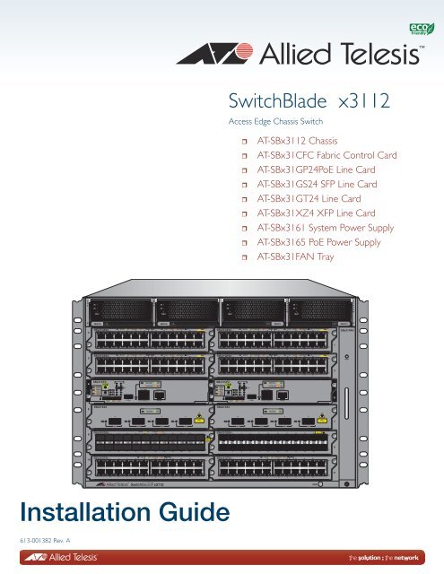
<strong>SwitchBlade</strong> <strong>x3112</strong><br />
Access Edge Chassis Switch<br />
<br />
<br />
<br />
<br />
<br />
<br />
<br />
<br />
<br />
AT-SB<strong>x3112</strong> Chassis<br />
AT-SBx31CFC Fabric Control Card<br />
AT-SBx31GP24PoE Line Card<br />
AT-SBx31GS24 SFP Line Card<br />
AT-SBx31GT24 Line Card<br />
AT-SBx31XZ4 XFP Line Card<br />
AT-SBx3161 System Power Supply<br />
AT-SBx3165 PoE Power Supply<br />
AT-SBx31FAN Tray<br />
P<br />
O<br />
E<br />
AC<br />
DC<br />
FAULT<br />
P<br />
O<br />
E<br />
AC<br />
DC<br />
FAULT<br />
AC<br />
DC<br />
FAULT<br />
S<br />
Y<br />
S<br />
T<br />
E<br />
M<br />
AC<br />
DC<br />
FAULT<br />
S<br />
Y<br />
S<br />
T<br />
E<br />
M<br />
SBx3165<br />
PoE<br />
POWER<br />
SBx3165<br />
PoE<br />
POWER<br />
SYSTEM<br />
POWER<br />
SBx3161<br />
SYSTEM<br />
POWER<br />
SBx3161<br />
0<br />
SBx31GP24<br />
0<br />
2 4 6 8 10 12 14 16 18 20<br />
plus<br />
22<br />
SBx31GP24<br />
0<br />
2 4 6 8 10 12 14 16 18 20<br />
plus<br />
22<br />
SBx31FAN<br />
1<br />
23<br />
1<br />
23<br />
1<br />
3 5 7 9 11<br />
13 15 17 19 21<br />
3 5 7 9 11<br />
13 15 17 19 21<br />
2<br />
SBx31GP24<br />
0<br />
2 4 6 8 10 12 14 16 18 20<br />
plus<br />
22<br />
SBx31GP24<br />
0<br />
2 4 6 8 10 12 14 16 18 20<br />
plus<br />
22<br />
POWER<br />
3<br />
1<br />
23<br />
1<br />
23<br />
3 5 7 9 11<br />
13 15 17 19 21<br />
3 5 7 9 11<br />
13 15 17 19 21<br />
4<br />
SBx31CFC<br />
SYS STATUS<br />
SYS STATUS<br />
RESET<br />
SD<br />
SBx STATUS<br />
0 1<br />
0 1<br />
2 3<br />
2 3<br />
4 5 CFC<br />
4 5 CFC<br />
6 7<br />
6 7<br />
8 9<br />
8 9<br />
10 11<br />
10 11<br />
L/A<br />
1000 LINK ACT<br />
10/100 LINK ACT<br />
NET MGMT<br />
CONSOLE<br />
SBx31CFC<br />
SYS STATUS<br />
RESET<br />
SD<br />
SBx STATUS<br />
0 1<br />
2 3<br />
4 5 CFC<br />
6 7<br />
8 9<br />
10 11<br />
L/A<br />
1000 LINK ACT<br />
10/100 LINK ACT<br />
NET MGMT<br />
CONSOLE<br />
5<br />
10/100/1000Base-T<br />
RS-232<br />
10/100/1000Base-T<br />
RS-232<br />
6<br />
SBx31XZ4<br />
PORT ACTIVITY<br />
10G LINK /<br />
ACT<br />
SBx31XZ4<br />
PORT ACTIVITY<br />
10G LINK /<br />
ACT<br />
0 1 2 3<br />
0 1 2 3<br />
7<br />
XFP XFP XFP XFP<br />
XFP XFP XFP XFP<br />
8<br />
SBx31GS24<br />
0<br />
2 4 6 8 10 12 14 16 18 20<br />
22<br />
SBx31GS24<br />
0<br />
2 4 6 8 10 12 14 16 18 20<br />
22<br />
9<br />
1<br />
23<br />
1<br />
23<br />
3 5 7 9 11<br />
13 15 17 19 21<br />
3 5 7 9 11<br />
13 15 17 19 21<br />
10<br />
SBx31GT24<br />
0<br />
2 4 6 8 10 12 14 16 18 20<br />
22<br />
SBx31GT24<br />
0<br />
2 4 6 8 10 12 14 16 18 20<br />
22<br />
11<br />
1<br />
23<br />
1<br />
23<br />
3 5 7 9 11<br />
13 15 17 19 21<br />
3 5 7 9 11<br />
13 15 17 19 21<br />
ESD<br />
<strong>Installation</strong> <strong>Guide</strong><br />
613-001382 Rev. A
Copyright © 2011 <strong>Allied</strong> <strong>Telesis</strong>, Inc.<br />
All rights reserved. No part of this publication may be reproduced without prior written permission from <strong>Allied</strong> <strong>Telesis</strong>,<br />
Inc.<br />
<strong>Allied</strong> <strong>Telesis</strong> and the <strong>Allied</strong> <strong>Telesis</strong> logo are trademarks of <strong>Allied</strong> <strong>Telesis</strong>, Incorporated. All other product names,<br />
company names, logos or other designations mentioned herein are trademarks or registered trademarks of their respective<br />
owners.<br />
<strong>Allied</strong> <strong>Telesis</strong>, Inc. reserves the right to make changes in specifications and other information contained in this document<br />
without prior written notice. The information provided herein is subject to change without notice. In no event shall <strong>Allied</strong><br />
<strong>Telesis</strong>, Inc. be liable for any incidental, special, indirect, or consequential damages whatsoever, including but not limited<br />
to lost profits, arising out of or related to this manual or the information contained herein, even if <strong>Allied</strong> <strong>Telesis</strong>, Inc. has<br />
been advised of, known, or should have known, the possibility of such damages.
Electrical Safety and Emissions Standards<br />
This product meets the following standards.<br />
Radiated Energy<br />
U.S. Federal Communications Commission<br />
Note: This equipment has been tested and found to comply with the limits for a Class A digital device pursuant to Part 15<br />
of FCC Rules. These limits are designed to provide reasonable protection against harmful interference when the<br />
equipment is operated in a commercial environment. This equipment generates, uses, and can radiate radio frequency<br />
energy and, if not installed and used in accordance with this instruction manual, may cause harmful interference to radio<br />
communications. Operation of this equipment in a residential area is likely to cause harmful interference in which case<br />
the user will be required to correct the interference at his own expense.<br />
Note: Modifications or changes not expressly approved of by the manufacturer or the FCC, can void your right to operate<br />
this equipment.<br />
Industry Canada<br />
This Class A digital apparatus complies with Canadian ICES-003.<br />
Cet appareil numérique de la classe A est conforme à la norme NMB-003 du Canada.<br />
European Union Restriction of the Use of Certain Hazardous Substances<br />
(RoHS) in Electrical and Electronic Equipment<br />
This <strong>Allied</strong> <strong>Telesis</strong> RoHS-compliant product conforms to the European Union Restriction of the Use of Certain Hazardous<br />
Substances (RoHS) in Electrical and Electronic Equipment. <strong>Allied</strong> <strong>Telesis</strong> ensures RoHS conformance by requiring<br />
supplier Declarations of Conformity, monitoring incoming materials, and maintaining manufacturing process controls.<br />
RFI Emissions<br />
FCC Class A, EN55022 Class A, EN61000-3-2, EN61000-3-3, VCCI<br />
Class A, C-TICK, CE<br />
Warning: In a domestic environment this product may cause radio interference in<br />
which case the user may be required to take adequate measures.<br />
Immunity<br />
EN55024<br />
Electrical Safety EN60950-1 (TUV), UL 60950-1 ( C UL US )<br />
Laser Safety<br />
EN60825<br />
3
Chapter :<br />
Translated Safety Statements<br />
Important: The indicates that a translation of the safety statement is available in a PDF<br />
document titled “Translated Safety Statements” on our web site at<br />
http://www.alliedtelesis.com/support.<br />
4
Contents<br />
Preface ............................................................................................................................................................ 11<br />
Safety Symbols Used in this Document..................................................................................................... 12<br />
Where to Find Web-based <strong>Guide</strong>s............................................................................................................. 13<br />
Contacting <strong>Allied</strong> <strong>Telesis</strong>............................................................................................................................ 14<br />
Online Support..................................................................................................................................... 14<br />
Email and Telephone Support ............................................................................................................. 14<br />
Warranty .............................................................................................................................................. 14<br />
Returning Products.............................................................................................................................. 14<br />
Sales or Corporate Information ........................................................................................................... 14<br />
Management Software Updates .......................................................................................................... 14<br />
Chapter 1: Overview ....................................................................................................................................... 15<br />
Introduction ................................................................................................................................................ 16<br />
AT-SB<strong>x3112</strong> Chassis................................................................................................................................. 17<br />
AT-SB<strong>x3112</strong> Chassis Slots ................................................................................................................. 18<br />
AT-SBx31CFC Fabric Control Card ........................................................................................................... 20<br />
AT-SBx31CFC Fabric Control Card Features ..................................................................................... 21<br />
Status LEDs......................................................................................................................................... 22<br />
eco-friendly Button............................................................................................................................... 24<br />
RESET Button ..................................................................................................................................... 24<br />
Network Management Port.................................................................................................................. 25<br />
Console (RS-232) Port ........................................................................................................................ 26<br />
USB Port.............................................................................................................................................. 27<br />
SD Card Slot........................................................................................................................................ 27<br />
SD Status LED .................................................................................................................................... 28<br />
AT-SBx31GT24 and AT-SBx31GP24 PoE Line Cards.............................................................................. 29<br />
Connector Type ................................................................................................................................... 30<br />
Speed .................................................................................................................................................. 30<br />
Duplex Mode ....................................................................................................................................... 30<br />
Maximum Distance .............................................................................................................................. 30<br />
Cable Type .......................................................................................................................................... 31<br />
Auto MDI/MDI-X .................................................................................................................................. 31<br />
Port Pinouts ......................................................................................................................................... 31<br />
AT-SBx31GT24 Port LEDs.................................................................................................................. 32<br />
AT-SBx31GP24 Port LEDs.................................................................................................................. 32<br />
AT-SBx31GP24 Power over Ethernet ................................................................................................. 34<br />
AT-SBx31GS24 SFP Line Card................................................................................................................. 37<br />
AT-SBx31GS24 LED ........................................................................................................................... 38<br />
AT-SBx31XZ4 XFP Line Card.................................................................................................................... 39<br />
AT-SBx31XZ4 LED.............................................................................................................................. 40<br />
AT-SBx3161 System Power Supply........................................................................................................... 41<br />
AT-SBx3161 Status LEDs ................................................................................................................... 41<br />
AT-SBx3165 PoE Power Supply................................................................................................................ 43<br />
AT-SBx3165 Status LEDs ................................................................................................................... 44<br />
AT-SBx31FAN Tray ................................................................................................................................... 45<br />
AT-SBx31FAN Tray POWER LED ......................................................................................................47<br />
5
Contents<br />
Chapter 2: <strong>Installation</strong> .....................................................................................................................................49<br />
Reviewing Safety Precautions....................................................................................................................50<br />
Selecting a Site for the <strong>SwitchBlade</strong> <strong>x3112</strong>................................................................................................53<br />
Installing the AT-SB<strong>x3112</strong> Chassis ............................................................................................................54<br />
Preparing the Equipment Rack ............................................................................................................55<br />
Unpacking the AT-SB<strong>x3112</strong> Chassis...................................................................................................56<br />
Adjusting the Brackets .........................................................................................................................57<br />
Installing the AT-SB<strong>x3112</strong> Chassis in Equipment Rack.......................................................................60<br />
Installing the Chassis Ground Lug .......................................................................................................62<br />
Protection Against Electrostatic Discharge (ESD)......................................................................................64<br />
Installing the AT-SBx3161 System Power Supply......................................................................................65<br />
Installing the AT-SBx3165 PoE Power Supply ...........................................................................................69<br />
Installing the AT-SBx31CFC Fabric Control Card ......................................................................................72<br />
Installing the Ethernet Line Cards ..............................................................................................................76<br />
Installing SFP Transceivers........................................................................................................................79<br />
Installing the XFP Transceivers..................................................................................................................82<br />
Replacing the AT-SBx31FAN Tray.............................................................................................................84<br />
Removing the Existing AT-SBx31FAN Tray.........................................................................................84<br />
Installing a New AT-SBx31FAN Tray ...................................................................................................85<br />
Cabling the Twisted-Pair or Fiber Optic Ports ............................................................................................87<br />
Installing the Chassis Blank Panels............................................................................................................88<br />
Applying A/C Power to the <strong>SwitchBlade</strong> <strong>x3112</strong> ..........................................................................................89<br />
Starting a Local Management Session.......................................................................................................93<br />
Chapter 3: Troubleshooting ............................................................................................................................95<br />
AT-SBx31CFC Fabric Control Card PSU Fault LED Flashing Amber........................................................96<br />
AT-SBx31CFC Fabric Control Card FAN Fault LED Flashing Amber ........................................................97<br />
AT-SBx31CFC Fabric Control Card SBx Status LEDs Flashing Amber.....................................................98<br />
AT-SBx31GP24 PoE Line Card Link LED is Off.........................................................................................99<br />
Power not Received on PoE Device.........................................................................................................100<br />
AT-SBx31GS24 SFP Line Card Fiber Optic Port Link LED is Off ............................................................101<br />
AT-SBx31XZ4 XFP Line Card Port LED is Off .........................................................................................102<br />
Cannot Establish a Local (Out-of-Band) Management Session ...............................................................104<br />
Appendix A: Technical Specifications ..........................................................................................................105<br />
Physical Specifications .............................................................................................................................105<br />
Environmental Specifications ...................................................................................................................106<br />
Power Specifications ................................................................................................................................107<br />
Safety and Electromagnetic Emissions Certifications ..............................................................................109<br />
Connectors and Port Pinouts....................................................................................................................110<br />
Cable Requirements.................................................................................................................................112<br />
6
List of Figures<br />
Figure 1: Front View of the AT-SB<strong>x3112</strong> Chassis ............................................................................................................... 17<br />
Figure 2: Rear View of the AT-SB<strong>x3112</strong> Chassis................................................................................................................ 18<br />
Figure 3: AT-SB<strong>x3112</strong> Chassis Slots .................................................................................................................................. 18<br />
Figure 4: AT-SBx31CFC Fabric Control Card ..................................................................................................................... 20<br />
Figure 5: System Status LEDs............................................................................................................................................. 22<br />
Figure 6: SBx STATUS LEDs.............................................................................................................................................. 23<br />
Figure 7: eco-friendly Button and Reset Button................................................................................................................... 24<br />
Figure 8: NET MGMT and CONSOLE Ports ....................................................................................................................... 25<br />
Figure 9: SD Card Slot and LED.......................................................................................................................................... 27<br />
Figure 10: AT-SBx31GT24 Line Card.................................................................................................................................. 29<br />
Figure 11: AT-SBx31GP24 PoE Line Card.......................................................................................................................... 29<br />
Figure 12: Port LEDs on the AT-SBx31GT24 Line Card ..................................................................................................... 32<br />
Figure 13: Port LEDs on the AT-SBx31GP24 PoE Line Card ............................................................................................. 32<br />
Figure 14: AT-SBx31GS24 SFP Line Card ......................................................................................................................... 37<br />
Figure 15: SFP Transceiver................................................................................................................................................. 37<br />
Figure 16: Port LED on the AT-SBx31GS24 SFP Line Card1............................................................................................. 38<br />
Figure 17: AT-SBx31XZ4 XFP Line Card............................................................................................................................ 39<br />
Figure 18: XFP Transceiver................................................................................................................................................. 39<br />
Figure 19: Port LED on the AT-SBx31XZ4 XFP Line Card ................................................................................................. 40<br />
Figure 20: AT-SBx3161 System Power Supply................................................................................................................... 41<br />
Figure 21: Status LEDs on the AT-SBx3161 System Power Supply................................................................................... 41<br />
Figure 22: AT-SBx3165 PoE Power Supply ........................................................................................................................ 43<br />
Figure 23: Status LEDs on the AT-SBx3165 PoE Power Supply ........................................................................................ 44<br />
Figure 24: AT-SBx31FAN Tray............................................................................................................................................ 45<br />
Figure 25: POWER LED on the AT-SBx31FAN Tray .......................................................................................................... 47<br />
Figure 26: 100 - 125 VAC 125 V NEMA 5-20 Plug and Receptacle.................................................................................... 53<br />
Figure 27: Reserving Vertical Rack Space.......................................................................................................................... 55<br />
Figure 28: Rack Mounting Hole Locations........................................................................................................................... 56<br />
Figure 29: Rack Mounting Bracket Locations...................................................................................................................... 58<br />
Figure 30: Rack Bracket Locations for Reverse Position of Chassis................................................................................... 59<br />
Figure 31: Lifting AT-SB<strong>x3112</strong> Chassis into Place.............................................................................................................. 60<br />
Figure 32: Installing the Rack Mount Screws ...................................................................................................................... 61<br />
Figure 33: Removing the Front Panel Shipping Brace Screws............................................................................................ 61<br />
Figure 34: Stripping the Grounding Wire ............................................................................................................................. 62<br />
Figure 35: Removing Ground Lug Screws........................................................................................................................... 62<br />
Figure 36: Attaching the Grounding Wire to the Grounding Lug.......................................................................................... 62<br />
Figure 37: Installing the Ground Lug and Wire.................................................................................................................... 63<br />
Figure 38: ESD Socket ........................................................................................................................................................ 64<br />
Figure 39: Slots A to D for System and PoE Power Supplies.............................................................................................. 65<br />
Figure 40: Unlocked Handle on the AT-SBx3161 System Power Supply............................................................................ 66<br />
Figure 41: Inserting the AT-SBx3161 System Power Supply .............................................................................................. 67<br />
Figure 42: Lock the Handle on the AT-SBx3161 System Power Supply............................................................................. 67<br />
Figure 43: Unlock the Handle on the AT-SBx3165 PoE Power Supply............................................................................... 70<br />
Figure 44: Inserting the AT-SBx3165 PoE Power Supply ................................................................................................... 70<br />
Figure 45: Locking the Handle on the AT-SBx3165 PoE Power Supply ............................................................................. 71<br />
Figure 46: Opening the Locking Handles of the AT-SBx31CFC Fabric Control Card ......................................................... 72<br />
Figure 47: Removing the Battery Insulator .......................................................................................................................... 73<br />
Figure 48: Aligning the AT-SBx31CFC Card in the Chassis Slot ........................................................................................ 73<br />
Figure 49: Inserting the AT-SBx31CFC Card in the Chassis Slot ....................................................................................... 74<br />
Figure 50: Closing the Locking Lever on the AT-SBx31CFC Fabric Control Card.............................................................. 74<br />
7
List of Figures<br />
Figure 51: Tightening Thumb Screws on the AT-SBx31CFC Card ..................................................................................... 75<br />
Figure 52: Aligning an Ethernet Line Card with a Chassis Slot ........................................................................................... 77<br />
Figure 53: Inserting an Ethernet Line Card.......................................................................................................................... 77<br />
Figure 54: Tightening Thumb Screws on an Ethernet Line Card......................................................................................... 78<br />
Figure 55: Remove SFP Slot Dust Cover ............................................................................................................................ 79<br />
Figure 56: Inserting the SFP Transceiver ............................................................................................................................ 80<br />
Figure 57: Removing the SFP Transceiver Protective Cover .............................................................................................. 80<br />
Figure 58: Removing the XFP Slot Dust Cover ................................................................................................................... 82<br />
Figure 59: Installing an XFP Transceiver............................................................................................................................. 82<br />
Figure 60: Removing the XFP Transceiver Protective Cover .............................................................................................. 83<br />
Figure 61: Loosening the AT-SBx31FAN Tray Thumb Screw ............................................................................................. 84<br />
Figure 62: Removing the AT-SBx31FAN Tray from the Chassis......................................................................................... 85<br />
Figure 63: Inserting the AT-SBx31FAN Tray into the Chassis............................................................................................. 86<br />
Figure 64: Tightening the AT-SBx31FAN Tray Thumb Screw............................................................................................. 86<br />
Figure 65: AC Sockets on the AT-SB<strong>x3112</strong> Chassis Rear Panel........................................................................................ 89<br />
Figure 66: Connecting AC Power Cord in rear of AT-SB<strong>x3112</strong> Chassis ............................................................................. 90<br />
Figure 67: Dress and Secure AC Power Cords ................................................................................................................... 91<br />
Figure 68: 100 - 125 VAC 125 V NEMA 5-20 Plug and Receptacle.................................................................................... 91<br />
Figure 69: Connecting the Management Cable to the Console RS-232 Port ...................................................................... 93<br />
Figure 70: Dual Ports of XFP Transceiver ......................................................................................................................... 102<br />
Figure 71: RJ-45 Connector and Port Pin Layout.............................................................................................................. 110<br />
8
List of Tables<br />
Table 1. Safety Symbols .....................................................................................................................................................12<br />
Table 2. <strong>SwitchBlade</strong> <strong>x3112</strong> Switch Components ..............................................................................................................16<br />
Table 3. AT-SB<strong>x3112</strong> Chassis Slots ...................................................................................................................................19<br />
Table 4. System Status LED Descriptions ..........................................................................................................................22<br />
Table 5. SBx STATUS LED Description on the Active AT-SBx31CFC Fabric Control Card ..............................................23<br />
Table 6. NET MGMT port LED Description ........................................................................................................................26<br />
Table 7. SD Status LED Descriptions .................................................................................................................................28<br />
Table 8. Port LED Descriptions on AT-SBx31GT24 Line Card ..........................................................................................32<br />
Table 9. Port LED Descriptions on AT-SBx31GP24 PoE Line Card ..................................................................................33<br />
Table 10. IEEE802.3at Classes versus AT-SBx31GP24 Power Levels .............................................................................35<br />
Table 11. Port LED Description on the AT-SBx31GP24 PoE Line Card ............................................................................38<br />
Table 12. Port LED Description on the AT-SBx31XZ4 XFP Line Card ...............................................................................40<br />
Table 13. Status LED Description on the AT-SBx3161 System Power Supply ..................................................................42<br />
Table 14. Status LED Description on the AT-SBx3165 PoE Power Supply .......................................................................44<br />
Table 15. POWER LED on the AT-SBx31FAN Tray ..........................................................................................................47<br />
Table 16. Front Panel to Rack Rail Dimensions .................................................................................................................57<br />
Table 17. MDI Pin Signals (10Base-T or 100Base-TX) ....................................................................................................110<br />
Table 18. MDI-X Pin Signals (10Base-T or 100Base-TX) ................................................................................................110<br />
Table 19. RJ-45 1000Base-T Connector Pinouts .............................................................................................................111<br />
Table 20. Cable Requirements for the 10/100/1000Base-T Management Port ................................................................112<br />
9
List of Tables<br />
10
Preface<br />
This guide provides the hardware installation instructions for your<br />
<strong>SwitchBlade</strong> <strong>x3112</strong> switch. This preface contains the following sections:<br />
“Safety Symbols Used in this Document” on page 12<br />
“Where to Find Web-based <strong>Guide</strong>s” on page 13<br />
“Contacting <strong>Allied</strong> <strong>Telesis</strong>” on page 14<br />
11
Preface<br />
Safety Symbols Used in this Document<br />
This document uses the safety symbols defined in Table 1.<br />
Table 1. Safety Symbols<br />
Symbol Meaning Description<br />
Caution<br />
Warning<br />
Performing or omitting a specific action may<br />
result in equipment damage or loss of data.<br />
Performing or omitting a specific action may<br />
result in electrical shock.<br />
12
<strong>SwitchBlade</strong> <strong>x3112</strong> <strong>Installation</strong> <strong>Guide</strong><br />
Where to Find Web-based <strong>Guide</strong>s<br />
The installation and user guides for all of the <strong>Allied</strong> <strong>Telesis</strong> products are<br />
available for viewing in portable document format (PDF) from our web site<br />
at www.alliedtelesis.com/support.<br />
13
Preface<br />
Contacting <strong>Allied</strong> <strong>Telesis</strong><br />
This section provides <strong>Allied</strong> <strong>Telesis</strong> contact information for technical<br />
support and for sales and corporate information.<br />
Online Support<br />
Email and<br />
Telephone<br />
Support<br />
Warranty<br />
Returning<br />
Products<br />
You may request technical support online by accessing the <strong>Allied</strong> <strong>Telesis</strong><br />
Knowledge Base: www.alliedtelesis.com/support. You may use the<br />
Knowledge Base to submit questions to our technical support staff and<br />
review answers to previously asked questions.<br />
For Technical Support via email or telephone, refer to the Support &<br />
Services section of the <strong>Allied</strong> <strong>Telesis</strong> web site:<br />
www.alliedtelesis.com/support. Select your country from the list<br />
displayed on the website and then select the appropriate menu tab.<br />
For hardware warranty information, refer to the <strong>Allied</strong> <strong>Telesis</strong> web site at<br />
www.alliedtelesis.com/support.<br />
Products for return or repair must first be assigned a return materials<br />
authorization (RMA) number. A product sent to <strong>Allied</strong> <strong>Telesis</strong> without an<br />
RMA number will be returned to the sender at the sender’s expense.<br />
To obtain an RMA number, contact the <strong>Allied</strong> <strong>Telesis</strong> Technical Support<br />
group at our web site: www.alliedtelesis.com/support. Select your<br />
country from the list displayed on the website. Then select the appropriate<br />
menu tab.<br />
Sales or<br />
Corporate<br />
Information<br />
Management<br />
Software Updates<br />
You can contact <strong>Allied</strong> <strong>Telesis</strong> for sales or corporate information through<br />
our web site at www.alliedtelesis.com. To find the contact information for<br />
your country, select Contact Us.<br />
New releases of management software for our managed products are<br />
available on our <strong>Allied</strong> <strong>Telesis</strong> web site at<br />
http://www.alliedtelesis.com/support.<br />
14
Chapter 1<br />
Overview<br />
This chapter provides descriptions of the <strong>SwitchBlade</strong> <strong>x3112</strong> chassis, line<br />
cards, power supplies and fan tray and contains the following sections:<br />
“Introduction” on page 16<br />
“AT-SB<strong>x3112</strong> Chassis” on page 17<br />
“AT-SBx31CFC Fabric Control Card” on page 20<br />
“AT-SBx31GT24 and AT-SBx31GP24 PoE Line Cards” on page 29<br />
“AT-SBx31GS24 SFP Line Card” on page 37<br />
“AT-SBx31XZ4 XFP Line Card” on page 39<br />
“AT-SBx3161 System Power Supply” on page 41<br />
“AT-SBx3165 PoE Power Supply” on page 43<br />
“AT-SBx31FAN Tray” on page 45<br />
15
Chapter 1: Overview<br />
Introduction<br />
The <strong>SwitchBlade</strong> <strong>x3112</strong> Switch is a modular enterprise access edge<br />
chassis scalable for GB and 10G Ethernet applications. It features<br />
redundant fabric switching architecture, copper and fiber line cards and<br />
system and PoE power supplies. The switch supports up to 240 GE ports<br />
or up to 40 10GE ports and can provide up to 2400W of PoE+ power; for<br />
example, 30W of Class 4 (IEEE 802.1at) PoE+ power can be provided for<br />
up to 80 ports.<br />
See Table 2 for the <strong>SwitchBlade</strong> <strong>x3112</strong> Switch components.<br />
Table 2. <strong>SwitchBlade</strong> <strong>x3112</strong> Switch Components<br />
Component Description Reference<br />
AT-SB<strong>x3112</strong> Chassis Rack mountable chassis with 12 line card slots, 2<br />
System power supply slots, 2 PoE power supply slots,<br />
and 1 fan tray slot<br />
page 17<br />
AT-SBx31CFC Fabric<br />
Control Card<br />
AT-SBx31GT24 and<br />
AT-SBx31GP24 PoE Line<br />
Card<br />
AT-SBx31XZ4 XFP Line<br />
Card<br />
Fabric switch controller page 20<br />
24 port 10/100/1000Base-T PoE Ethernet line card page 29<br />
4 port 10GE XFP Ethernet line card page 39<br />
AT-SBx3161 System<br />
Power Supply<br />
AT-SBx3165 PoE Power<br />
Supply<br />
AT-SBx31FAN Tray<br />
AC power input, with system output voltage of 12VDC<br />
and output power of 1200 W<br />
AC power input, with PoE output voltage of 56VDC and<br />
output power of 1200 W<br />
Contains 4 fans, 3 temperature sensors, and a<br />
controller board<br />
page 41<br />
page 43<br />
page 45<br />
16
POWER<br />
<strong>SwitchBlade</strong> <strong>x3112</strong> <strong>Installation</strong> <strong>Guide</strong><br />
AT-SB<strong>x3112</strong> Chassis<br />
The AT-SB<strong>x3112</strong> Chassis has a modular design that is seven Rack Units<br />
(RU’s) high. It contains a high-speed backplane which has the capacity for<br />
the following:<br />
Up to two switching fabric line cards<br />
Up to ten Ethernet line cards<br />
Up to two AC system power supplies<br />
Up to two PoE power supplies<br />
One fan tray<br />
Four individual A/C PSU plugs are provided on the rear panel for the<br />
power supply slot.<br />
The chassis provides high resiliency with a passive backplane, capacity for<br />
ten line cards, redundant controller cards and power supplies The chassis<br />
supports up to 40 ports at 10 Gbps of full-duplex data exchange or 400<br />
Gbps switching throughput capacity.<br />
All of the controllers, line cards, power supplies and the fan tray are hotswappable.<br />
Figure 1 and Figure 2 on page 18 show the front and rear views of the<br />
AT-SB<strong>x3112</strong> Chassis as shipped from the factory. The AT-SBx31FAN<br />
Tray is pre-installed in the chassis at the factory.<br />
P<br />
O<br />
E<br />
P<br />
O<br />
E<br />
S<br />
Y<br />
S<br />
T<br />
E<br />
M<br />
S<br />
Y<br />
S<br />
T<br />
E<br />
M<br />
0<br />
SBx31FAN<br />
1<br />
2<br />
3<br />
4<br />
5<br />
6<br />
7<br />
8<br />
9<br />
10<br />
11<br />
ESD<br />
1782<br />
Figure 1 Front View of the AT-SB<strong>x3112</strong> Chassis<br />
17
AC<br />
DC<br />
FAULT<br />
0<br />
1<br />
0<br />
1<br />
SYS STATUS<br />
SYS STATUS<br />
M/S MASTER<br />
SLAVE<br />
PSU NORMAL<br />
FAULT<br />
NORMAL<br />
FAN<br />
FAULT<br />
0<br />
1<br />
0<br />
1<br />
AC<br />
DC<br />
FAULT<br />
2 4 6 8 10 12 14 16 18 20<br />
3 5 7 9 11<br />
2 4 6 8 10 12 14 16 18 20<br />
3 5 7 9 11<br />
SBx STATUS<br />
0 1<br />
0 1<br />
2 3<br />
2 3<br />
4 5 CFC<br />
4 5 CFC<br />
6 7<br />
M/S 6 7<br />
8 9<br />
PSU 8 9<br />
10 11<br />
RESET FAN 10 11<br />
SD<br />
READY BUSY FAULT<br />
L/A<br />
10/100/1000Base-T<br />
13 15 17 19 21<br />
1000 LINK ACT 10/100 LINK ACT<br />
2 4 6 8 10 12 14 16 18 20<br />
3 5 7 9 11<br />
3 5 7 9 11<br />
1000 LINK ACT<br />
10/100 LINK ACT<br />
NET MGMT<br />
CONSOLE<br />
PORT ACTIVITY<br />
10G LINK /<br />
13 15 17 19 21<br />
RS-232<br />
0 1 2 3<br />
XFP XFP XFP XFP<br />
13 15 17 19 21<br />
2 4 6 8 10 12 14 16 18 20<br />
ACT<br />
13 15 17 19 21<br />
22<br />
23<br />
22<br />
23<br />
22<br />
23<br />
22<br />
23<br />
0<br />
1<br />
0<br />
1<br />
SYS STATUS<br />
M/S MASTER<br />
SLAVE<br />
PSU NORMAL<br />
FAULT<br />
NORMAL<br />
FAN<br />
FAULT<br />
0<br />
1<br />
0<br />
1<br />
AC<br />
DC<br />
FAULT<br />
3 5 7 9 11<br />
SBx STATUS<br />
0 1<br />
2 3<br />
4 5 CFC<br />
M/S 6 7<br />
PSU 8 9<br />
RESET FAN 10 11<br />
SD<br />
READY BUSY FAULT<br />
L/A<br />
10/100/1000Base-T<br />
1000 LINK ACT<br />
10/100 LINK ACT<br />
NET MGMT<br />
CONSOLE<br />
RS-232<br />
AC<br />
DC<br />
FAULT<br />
2 4 6 8 10 12 14 16 18 20<br />
13 15 17 19 21<br />
2 4 6 8 10 12 14 16 18 20<br />
3 5 7 9 11<br />
2 4 6 8 10 12 14 16 18 20<br />
3 5 7 9 11<br />
3 5 7 9 11<br />
PORT ACTIVITY<br />
10G LINK /<br />
13 15 17 19 21<br />
0 1 2 3<br />
XFP XFP XFP XFP<br />
13 15 17 19 21<br />
2 4 6 8 10 12 14 16 18 20<br />
ACT<br />
13 15 17 19 21<br />
22<br />
23<br />
22<br />
23<br />
22<br />
23<br />
22<br />
23<br />
POWER<br />
Chapter 1: Overview<br />
P<br />
O<br />
E<br />
AC INPUT 100-240VAC~<br />
C<br />
SYSTEM PSU<br />
A<br />
POE PSU<br />
D<br />
SYSTEM PSU<br />
B<br />
POE PSU<br />
POWER SUPPLY INTERFACE<br />
A and C PSU<br />
B and D PSU<br />
1783<br />
Figure 2 Rear View of the AT-SB<strong>x3112</strong> Chassis<br />
AT-SB<strong>x3112</strong><br />
Chassis Slots<br />
The AT-SB<strong>x3112</strong> Chassis has four power supply slots, 12 line card slots,<br />
and one fan tray slot. The slot configuration of the AT-SB<strong>x3112</strong> Chassis is<br />
displayed in Figure 3 and the components available for each slot are<br />
described in Table 3 on page 19.<br />
Power Supply Slots<br />
A B C D<br />
P<br />
O<br />
E<br />
P<br />
O<br />
E<br />
S<br />
Y<br />
S<br />
T<br />
E<br />
M<br />
S<br />
Y<br />
S<br />
T<br />
E<br />
M<br />
SBx3165<br />
PoE<br />
POWER<br />
SBx3165<br />
PoE<br />
POWER<br />
SYSTEM<br />
POWER<br />
SBx3161<br />
SYSTEM<br />
POWER<br />
SBx3161<br />
Slots 0 & 1<br />
0<br />
SBx31GP24<br />
plus<br />
SBx31GP24<br />
plus<br />
SBx31FAN<br />
1<br />
Slots 2 & 3<br />
2<br />
SBx31GP24<br />
plus<br />
SBx31GP24<br />
plus<br />
3<br />
Line Card Slots<br />
Slots 4 & 5<br />
Slots 6 & 7<br />
Slots 8 & 9<br />
4<br />
6<br />
8<br />
SBx31CFC<br />
SBx31XZ4<br />
SBx31GS24<br />
SBx31CFC<br />
SBx31XZ4<br />
SBx31GS24<br />
5<br />
7<br />
9<br />
FAN Tray Slot<br />
Slots 10 & 11<br />
10<br />
SBx31GT24<br />
SBx31GT24<br />
11<br />
ESD<br />
2035<br />
Figure 3 AT-SB<strong>x3112</strong> Chassis Slots<br />
18
<strong>SwitchBlade</strong> <strong>x3112</strong> <strong>Installation</strong> <strong>Guide</strong><br />
Table 3. AT-SB<strong>x3112</strong> Chassis Slots<br />
Slot<br />
A and B<br />
C and D<br />
Line Cards/Power Supplies<br />
These slots are reserved for the primary and redundant<br />
AT-SBx3165 PoE Power Supplies. Each slot can<br />
accommodate one power supply.<br />
These slots are reserved for the primary and redundant<br />
AT-SBx3161 System Power Supplies. Each slot can<br />
accommodate one power supply.<br />
4 and 5 These slots are reserved exclusively for the primary<br />
and redundant AT-SBx31CFC Fabric Control Cards.<br />
Each slot can accommodate one card.<br />
0 to 3,<br />
6 to 11<br />
These slots are designed for any combination of<br />
AT-SBx31GP24, AT-SBx31GS24, AT-SBx31GT24,<br />
and the AT-SBx31XZ4 Line Cards. Each slot can<br />
accommodate one card.<br />
19
Chapter 1: Overview<br />
AT-SBx31CFC Fabric Control Card<br />
The AT-SBx31CFC Fabric Control Card provides two functions: the<br />
central switching fabric between all the Ethernet line cards and the central<br />
controller for management and control of the chassis.<br />
Note<br />
One AT-SBx31CFC supports up to 200 Gbps of bidirectional<br />
Ethernet traffic. When two AT-SBx31CFC Fabric Control Cards are<br />
installed, the switching load of the network traffic is shared between<br />
the switching fabric circuitry on each of the line cards resulting in a<br />
potential system throughput of 400 Gbps.<br />
The Switchblade <strong>x3112</strong> Management Software resides on the<br />
AT-SBx31CFC Fabric Control Card which monitors and configures the line<br />
cards via the controller circuitry. Either one or two AT-SBx31CFC Fabric<br />
Control Cards may be installed yielding a non-redundant or redundant<br />
controller configuration respectively.<br />
SBx31CFC<br />
SBx STATUS<br />
0 1<br />
1000 LINK ACT<br />
SYS STATUS<br />
M/S MASTER<br />
SLAVE<br />
PSU NORMAL<br />
FAULT<br />
NORMAL<br />
FAN<br />
FAULT<br />
RESET<br />
M/S<br />
PSU<br />
FAN<br />
SD<br />
2<br />
4<br />
6<br />
8<br />
10<br />
3<br />
5 CFC<br />
7<br />
9<br />
11<br />
L/A<br />
10/100 LINK ACT<br />
NET MGMT<br />
CONSOLE<br />
READY BUSY FAULT<br />
10/100/1000Base-T<br />
RS-232<br />
Figure 4 AT-SBx31CFC Fabric Control Card<br />
Note<br />
The AT-SBx31CFC Fabric Control Card can only be installed in slots<br />
4 or 5 of the AT-SB<strong>x3112</strong> Chassis.<br />
Note<br />
The CLI mnemonic for the AT-SBx31CFC Fabric Control Card in the<br />
Switchblade <strong>x3112</strong> Management Software is “CFC200”.<br />
20
<strong>SwitchBlade</strong> <strong>x3112</strong> <strong>Installation</strong> <strong>Guide</strong><br />
AT-SBx31CFC<br />
Fabric Control<br />
Card Features<br />
The AT-SBx31CFC Fabric Control Card supports the following features:<br />
<br />
<br />
<br />
<br />
<br />
<br />
<br />
<br />
<br />
<br />
<br />
<br />
Supports up to 40 ports at 10 Gbps of full-duplex data exchange or<br />
400 Gbps switching throughput capacity with two AT-SBx31CFC<br />
Fabric Control Cards installed.<br />
Supports a non-redundant switching configuration with one<br />
AT-SBx31CFC Fabric Control Card installed. This configuration is<br />
non-blocking if the Ethernet traffic on each line card does not exceed a<br />
line rate of 20 Gbps.<br />
Supports a redundant, non-blocking switching configuration with two<br />
AT-SBx31CFC Fabric Control Cards installed.<br />
Centralized LED for status of all line cards installed in the AT-SB<strong>x3112</strong><br />
Chassis.<br />
Supports an eco-friendly button for enabling/disabling port and status<br />
LEDs on all line cards.<br />
Provides a system reset switch.<br />
Supports an SD Card slot for data storage and retrieval.<br />
Provides a USB port for data storage and retrieval on a USB device.<br />
Supports a remote management via a 10/100/1000 Base-T network<br />
management port.<br />
Supports local management via an RS-232 CONSOLE port.<br />
Front loading access is provided for servicing.<br />
Supports a hot swappable design for all modules.<br />
21
Chapter 1: Overview<br />
Status LEDs<br />
The AT-SBx31CFC Fabric Control Card has two types of status LEDs on<br />
the front panel:<br />
<br />
“System Status LEDs” , next<br />
“SBx STATUS LEDs” on page 23<br />
System Status LEDs<br />
The System Status LEDs on the AT-SBx31CFC Fabric Control Card<br />
display general status information about the management system status,<br />
the power supplies, and the Fan Tray. These LEDs are displayed in<br />
Figure 5 and described in Table 4 on page 22.<br />
M/S<br />
PSU<br />
FAN<br />
1816<br />
Figure 5 System Status LEDs<br />
Table 4. System Status LED Descriptions<br />
LED State Description<br />
M/S<br />
PSU<br />
FAN<br />
Solid Green<br />
Solid Amber<br />
Flashing<br />
Amber<br />
Solid Green<br />
Flashing<br />
Amber<br />
Solid Green<br />
Flashing<br />
Amber<br />
The AT-SBx31CFC Fabric Control Card is the<br />
active management controller.<br />
The AT-SBx31CFC Fabric Control Card is the<br />
inactive management controller or disabled.<br />
The AT-SBx31CFC Fabric Control Card is ‘Out of<br />
Sync’.<br />
All configured power supplies are operating<br />
properly.<br />
A FAULT condition has occurred where one or<br />
more of the configured power supplies are<br />
operating outside of the normal temperature or<br />
voltage ranges. Check the individual power<br />
supply LEDs to determine which power supply<br />
has a fault condition.<br />
The Fan Tray is operating properly.<br />
A FAULT condition has occurred where one or<br />
more fans are not operating at the proper speed.<br />
22
<strong>SwitchBlade</strong> <strong>x3112</strong> <strong>Installation</strong> <strong>Guide</strong><br />
SBx STATUS LEDs<br />
The SBx STATUS LEDs on the active AT-SBx31CFC Fabric Control Card<br />
display the general operating states of the Ethernet line cards and the<br />
management cards in slots 0 through 11 of the chassis. For the location of<br />
the slots, see Table 3 on page 18. There is one LED per slot. These LEDs<br />
are displayed in Figure 6 and described in Table 5.<br />
SBx STATUS<br />
0 1<br />
2 3<br />
4 5<br />
CFC<br />
6 7<br />
8 9<br />
10 11<br />
1817<br />
Figure 6 SBx STATUS LEDs<br />
Table 5. SBx STATUS LED Description on the Active AT-SBx31CFC<br />
Fabric Control Card<br />
LEDs State Description<br />
0 to 11<br />
Off<br />
Solid Green<br />
Flashing Green<br />
Solid Amber<br />
Flashing Amber<br />
Indicates that the slot is empty.<br />
Indicates that the line card is operating<br />
normally.<br />
Indicates that the line card is booting up, in<br />
test, or loading a configuration file.<br />
Indicates that the line card is in an off-line,<br />
reset, or disabled state. You can remove<br />
the line card from the chassis while it is in<br />
this state.<br />
Indicates that the line card is reporting a<br />
failure condition. Use the CLI commands to<br />
obtain the specific problem.<br />
23
Chapter 1: Overview<br />
eco-friendly<br />
Button<br />
The eco-friendly button on the AT-SBx31CFC Fabric Control Card front<br />
panel controls the activation of the status LEDs on all the chassis line<br />
cards and AT-SBx31CFC Fabric Control Card and to initiate a lamp test<br />
on all status LEDs. It is displayed in Figure 7.<br />
You may elect to turn off the LEDs when you are not using them to monitor<br />
the status on the line card ports or the overall system status. When the<br />
LEDs are turned off via the eco-friendly switch, all of the LEDs in the<br />
chassis are affected except for the M/S LED on the AT-SBx31CFC Fabric<br />
Control Card(s) which is always illuminated. Also, the overall power<br />
consumption of the chassis is slightly reduced – approximately 3 watts in a<br />
system with 240 active copper ports.<br />
Each time the eco-friendly button is pushed, a lamp test is initiated on all<br />
LEDs in the chassis. The lamp test consists of LEDs flashing in alternating<br />
colors for 3 seconds.<br />
RESET<br />
Figure 7 eco-friendly Button and Reset Button<br />
RESET Button<br />
You can use the RESET button to reset the controller and switch fabric<br />
circuitry on the AT-SBx31CFC Fabric Control Card.This button is<br />
displayed in Figure 7. Push the button only in the unlikely event that the<br />
Switchblade <strong>x3112</strong> Management Software is not responsive to CLI<br />
commands or status requests. Depending on your configuration, you may<br />
initiate a short interruption in the flow of network traffic through the switch<br />
when you press the button.<br />
If you press the RESET button with only one AT-SBx31CFC Fabric<br />
Control Card installed, which is the active controller, all of the Ethernet line<br />
cards are reset by the AT-SBx31CFC Fabric Control Card as part of its<br />
boot up process.<br />
Caution<br />
When the RESET button is pressed with only one AT-SBx31CFC<br />
Fabric Control Card installed, the Ethernet network traffic flow<br />
through the switch is interrupted for up to two minutes while the<br />
AT-SBx31CFC and Ethernet line cards reboot.<br />
24
<strong>SwitchBlade</strong> <strong>x3112</strong> <strong>Installation</strong> <strong>Guide</strong><br />
If you press the RESET button with two AT-SBx31CFC Fabric Control<br />
Cards installed, the role of the active controller is “swapped” with the<br />
inactive controller. This means that the inactive controller becomes the<br />
active controller and the active controller becomes the inactive or standby<br />
controller. During this process, the switch management function is<br />
swapped to the new active controller. In this case, the inactive<br />
AT-SBx31CFC becomes active immediately, and consequently, the<br />
Ethernet line cards are not affected or reset.<br />
Caution<br />
With two AT-SBx31CFC Fabric Control Cards installed, the<br />
switching fabric circuitry on each line card is shared. When you<br />
press the RESET button, the Ethernet network traffic flow through<br />
the switch is limited to 200 Gbps for up to two minutes. This is the<br />
time required for the inactive AT-SBx31CFC Fabric Control Card to<br />
reboot and for its switching fabric circuitry to become available again<br />
for switching network traffic.<br />
Note<br />
The RESET switch is specifically provided for resetting the<br />
AT-SBx31CFC Fabric Control Card. If you want to swap the<br />
controller function between the active and standby AT-SBx31CFC<br />
Fabric Control Cards, <strong>Allied</strong> <strong>Telesis</strong> recommends that you use the<br />
SWAP commands provided in the Switchblade <strong>x3112</strong> Management<br />
Software. Refer the to the Software Reference for <strong>SwitchBlade</strong><br />
x3100 Series Switches on the ATI web site for specific information.<br />
Network<br />
Management<br />
Port<br />
The Network Management (NET MGMT) port is an RJ-45, 10/100/1000<br />
Ethernet port. See Figure 8. This port provides an Ethernet interface for<br />
remote management of the <strong>SwitchBlade</strong> <strong>x3112</strong> Switch. Because this port<br />
is intended to be connected to the network, you can connect an Ethernet<br />
cable between the Network Management port and one of the Ethernet line<br />
cards in the chassis. This provides a connection to a remote management<br />
device or PC on the network via the AT-SB<strong>x3112</strong> line cards.<br />
1000 LINK ACT<br />
10/100 LINK ACT<br />
NET MGMT<br />
CONSOLE<br />
L/A<br />
10/100/1000Base-T<br />
RS-232<br />
Figure 8 NET MGMT and CONSOLE Ports<br />
1820<br />
25
Chapter 1: Overview<br />
The NET MGMT port is a standard RJ-45 8-pin connector and can operate<br />
at 10, 100, or 1000 Mbps in either half- or full-duplex mode. The cable<br />
requirements for this port can be found in the table “Cable Requirements<br />
for the 10/100/1000Base-T Management Port” on page 112. For the port<br />
pinouts, refer to “Connectors and Port Pinouts” on page 110.<br />
The default setting for the Management port is Auto-Negotiation with Auto<br />
MDI/MDI-X. At the default setting, the port, which is IEEE 802.3u<br />
compliant, sets its speed and duplex mode automatically with<br />
Auto-Negotiation. You can disable Auto-Negotiation and set the speed<br />
and duplex mode manually.<br />
The wiring configuration of the port is set automatically with<br />
Auto MDI/MDI-X to MDI or MDI-X, depending on the wiring configuration<br />
of the end node. This allows you to use a straight-through twisted-pair<br />
cable regardless of the wiring configuration of the port on the network<br />
device. The Auto MDI/MDI-X feature is only available when the port is<br />
using Auto-Negotiation. If the Auto-Negotiation feature is disabled with the<br />
Switchblade <strong>x3112</strong> Management Software, the port defaults to the MDI-X<br />
setting.<br />
NET MGMT LED<br />
The Network Management (NET MGMT) port on the AT-SBx31CFC<br />
Fabric Control Card has one Status LED as displayed in Figure 8 and<br />
described in Table 6.<br />
Table 6. NET MGMT port LED Description<br />
LED State Description<br />
L/A<br />
Solid Green<br />
Flashing<br />
Green<br />
Solid Amber<br />
Flashing<br />
Amber<br />
The port has a valid 1000 Mbps link.<br />
The port is transmitting or receiving data at<br />
1000 Mbps.<br />
The port has a valid 100 or 10 Mbps link.<br />
The port is transmitting or receiving data at<br />
100 or 10 Mbps.<br />
Console (RS-232)<br />
Port<br />
You use this port for local management with a console or a PC with a<br />
terminal emulation program. See Figure 8. This port does not require the<br />
AT-SBx31CFC Fabric Control Card to have an Internet Protocol (IP)<br />
address and is referred to as local or out-of-band management because it<br />
is not conducted over a network.<br />
When initially configuring your <strong>SwitchBlade</strong> <strong>x3112</strong> Switch, you first<br />
connect to this port with an RS-232 Serial Management cable. The cable<br />
is provided with the AT-SBx31CFC Fabric Control Card.<br />
26
<strong>SwitchBlade</strong> <strong>x3112</strong> <strong>Installation</strong> <strong>Guide</strong><br />
For instructions on how to start a local management session, refer to<br />
Chapter 2, “Starting a Local Management Session” on page 93 or refer to<br />
the Software Reference for <strong>SwitchBlade</strong> x3100 Series Switches on the<br />
ATI web site. Go to “Where to Find Web-based <strong>Guide</strong>s” on page 13 for<br />
information about how to navigate to this document.<br />
USB Port<br />
The USB slot is an interface designed for temporary storage of<br />
configuration files on a memory stick. This interface is presently<br />
unsupported by the Switchblade <strong>x3112</strong> Management Software and will be<br />
available in future software releases.<br />
SD Card Slot The SD slot for a secure digital memory (SD) card is displayed in Figure 9<br />
and is used in the following situations:<br />
<br />
<br />
Storing backup copies of the master configuration file on the<br />
AT-SBx31CFC Fabric Control Card. You can maintain a library of past<br />
configuration files of a chassis so that you can return a unit to a<br />
previous configuration.<br />
Transferring master configuration files between chassis - You can<br />
configure units that are to have similar configurations by transferring<br />
the master configuration file with a secure digital memory card.<br />
SD<br />
READY BUSY FAULT<br />
1818<br />
Figure 9 SD Card Slot and LED<br />
An SD card is optional. The AT-SBx31CFC Fabric Control Card can<br />
operate without a memory card.<br />
The following SD flash memory cards are officially supported in the first<br />
release.<br />
<br />
<br />
SanDisk 2GB Flash card<br />
SanDisk 4GB SDHC Flash card<br />
Note<br />
Other brands can be used but are not guaranteed to work.<br />
For ordering information, contact your <strong>Allied</strong> <strong>Telesis</strong> sales representative<br />
or visit our web site.<br />
27
Chapter 1: Overview<br />
SD Status LED<br />
The SD Status LED on the AT-SBx31CFC Fabric Control Card is<br />
displayed in Figure 9 on page 27 and described in Table 7.<br />
Table 7. SD Status LED Descriptions<br />
LEDs State Description<br />
SD<br />
Off<br />
Solid Green<br />
Flashing Green<br />
Flashing Amber<br />
The SD slot is empty or the SD card is improperly<br />
installed or the SD slot is deactivated through the<br />
Switchblade <strong>x3112</strong> Management Software.<br />
The SD Card is properly installed in the slot and is<br />
ready. You can safely remove the SC Card in this<br />
state.<br />
The AT-SBx31CFC Fabric Control Card is<br />
retrieving or storing data on the SD Card.<br />
The AT-SBx31CFC Fabric Control Card has<br />
detected a problem with the SD card. The line card<br />
may be installed improperly in the slot or there may<br />
be a problem with the line card itself.<br />
Caution<br />
A loss of data may occur if you remove your SD card when the SD<br />
status LED is flashing green.<br />
Before removing the card, use the DEACTIVATE MEDIA in the<br />
Switchblade <strong>x3112</strong> Management Software. Wait for the SD status<br />
LED to turn off before removing the card.<br />
28
<strong>SwitchBlade</strong> <strong>x3112</strong> <strong>Installation</strong> <strong>Guide</strong><br />
AT-SBx31GT24 and AT-SBx31GP24 PoE Line Cards<br />
The AT-SBx31GT24 Line Card provides 24 10/100/1000 Base-T Ethernet<br />
switching capability. All ports are RJ-45 connectors. See Figure 10.<br />
SBx31GT24<br />
0<br />
2 4 6 8 10 12 14 16 18 20<br />
22<br />
1<br />
3 5 7 9 11<br />
13 15 17 19 21<br />
23<br />
2022<br />
Figure 10 AT-SBx31GT24 Line Card<br />
The AT-SBx31GP24 PoE Line Card provides 24 10/100/1000 Base-T<br />
Ethernet switching capability with Power over Ethernet (PoE). All ports are<br />
RJ-45 connectors. See Figure 11.<br />
SBx31GP24<br />
0<br />
2 4 6 8 10 12 14 16 18 20<br />
plus<br />
22<br />
1<br />
3 5 7 9 11<br />
13 15 17 19 21<br />
23<br />
Figure 11 AT-SBx31GP24 PoE Line Card<br />
Both line cards have the following features except where noted:<br />
<br />
Store and Forward switching supports line rates of:<br />
– 1,480,000 pps (1000 Mbps)<br />
– 148,000 pps (100 Mbps)<br />
– 14,800 pps (10 Mbps)<br />
<br />
<br />
<br />
<br />
<br />
<br />
<br />
<br />
<br />
Jumbo frames supported up to 10 K<br />
Non-blocking full-wire speed switching on all packet sizes<br />
MAC address table capacity of up to 16K addresses with automatic<br />
aging<br />
Flow control in full-duplex operation<br />
Back pressure in half-duplex operation<br />
Auto MDI/MDI-X.<br />
Port status LEDs adjacent to each port<br />
Hot swappable<br />
AT-SBx31GP24 PoE Line Card only - Up to 30W of Class 4 (IEEE<br />
802.1at) PoE+ power for each port<br />
29
Chapter 1: Overview<br />
Note<br />
The AT-SBx31GP24 and AT-SBx31GT24 line cards can only be<br />
installed in slots 0 through 3 or 6 through 11 in the AT-SB<strong>x3112</strong><br />
Chassis.<br />
Note<br />
In the Switchblade <strong>x3112</strong> Management Software, the CLI mnemonic<br />
for these line cards are as follows:<br />
AT-SBx31GT24 Line Card - “GE24RJ”<br />
AT-SBx31GP24 PoE Line Card - “GE24POE”.<br />
Connector Type<br />
Speed<br />
The ports are 8-pin RJ-45 connectors that use four pins at 10 or 100 Mbps<br />
and all eight pins at 1000 Mbps. For the pin assignments, refer to<br />
“Connectors and Port Pinouts” on page 110.<br />
A port’s speed can be 10, 100, or 1000 Mbps. The speed can be set<br />
automatically through Auto-Negotiation, the default setting, or manually<br />
with the Switchblade <strong>x3112</strong> Management Software.<br />
Note<br />
To operate at 1000 Mbps, a twisted-pair port is set to Auto -<br />
Negotiation. You cannot set the speed of a twisted-pair port to<br />
1000 Mbps manually.<br />
Duplex Mode<br />
A twisted-pair port can operate in either half- or full-duplex mode. (Fullduplex<br />
mode is the only mode available when a port is operating at 1000<br />
Mbps.) The twisted-pair ports are IEEE 802.3u-compliant and Auto-<br />
Negotiate the duplex mode setting.<br />
You can disable Auto-Negotiation on one or all of the switch ports so that<br />
you can set the duplex mode manually through the Switchblade <strong>x3112</strong><br />
Management Software.<br />
Note<br />
If a switch port connected to a 10 or 100 Mbps end node that is not<br />
using Auto-Negotiation, you should not use Auto-Negotiation to set<br />
the speed and duplex mode, because a duplex mode mismatch<br />
might occur. You should disable Auto-Negotiation and set the port’s<br />
speed and duplex mode manually with the Switchblade <strong>x3112</strong><br />
Management Software.<br />
Maximum<br />
Distance<br />
The ports have a maximum operating distance of 100 meters (328 feet).<br />
30
<strong>SwitchBlade</strong> <strong>x3112</strong> <strong>Installation</strong> <strong>Guide</strong><br />
Cable Type<br />
The cabling requirements for a 10/100/1000Base-T port are:<br />
For 10 Mbps operation: Standard TIA/EIA 568-B-compliant Category 3<br />
or better shielded or unshielded cabling with 100 ohm impedance and<br />
a frequency of 16 MHz.<br />
For 100 Mbps operation: Standard TIA/EIA 568-A-compliant Category<br />
5 or TIA/EIA 568-B-compliant Enhanced Category 5 (Cat 5e) shielded<br />
or unshielded cabling with 100 ohm impedance and a frequency of 100<br />
MHz.<br />
For 1000 Mbps operation: Standard TIA/EIA 568-A-compliant<br />
Category 5 or TIA/EIA 568-B-compliant Enhanced Category 5 (Cat 5e)<br />
shielded or unshielded cabling with 100 ohm impedance and a<br />
frequency of 100 MHz.<br />
Auto MDI/<br />
MDI-X<br />
The twisted-pair ports on the switch are IEEE 802.3ab compliant and<br />
feature Auto MDI/MDI-X. This feature, available when a port’s speed and<br />
duplex mode are set through Auto-Negotiation, automatically configures a<br />
switch port to MDI or MDI-X depending on the wiring configuration of the<br />
port on the end node. This allows you to connect any network device to a<br />
port on the switch using a straight-through twisted-pair cable.<br />
If Auto-Negotiation is disabled on a port and the speed and duplex mode<br />
are set manually, the Auto MDI/MDI-X feature is also disabled and the<br />
port’s wiring configuration defaults to the MDI-X setting.<br />
Port Pinouts<br />
Refer to Table 17 on page 110 for the port pinouts when a twisted-pair port<br />
operates at 10 or 100 Mbps in the MDI configuration and Table 18 on<br />
page 110 for the MDI-X configuration. For port pinouts when a twisted-pair<br />
port operates at 1000 Mbps, refer to Table 19 on page 111.<br />
31
Chapter 1: Overview<br />
AT-SBx31GT24<br />
Port LEDs<br />
Each port on the AT-SBx31GT24 Line Card has two status LED as<br />
displayed in Figure 12 and described in Table 8.<br />
L/A<br />
Not Used<br />
2 4<br />
3 5<br />
Figure 12 Port LEDs on the AT-SBx31GT24 Line Card<br />
Table 8. Port LED Descriptions on AT-SBx31GT24 Line Card<br />
LED State Description<br />
L/A<br />
Solid Green<br />
Flashing<br />
Green<br />
Solid Amber<br />
Flashing<br />
Amber<br />
The port has a valid 1000 Mbps link.<br />
The port is transmitting or receiving data at 1000<br />
Mbps.<br />
The port has a valid 100 or 10 Mbps link.<br />
The port is transmitting or receiving data at 100 or<br />
10 Mbps.<br />
Right LED - The LED on the right side of each port is not used.<br />
AT-SBx31GP24<br />
Port LEDs<br />
Each port on the AT-SBx31GP24 PoE Line Card has two status LED as<br />
displayed in Figure 13 and described in Table 9.<br />
L/A<br />
PoE<br />
2 4<br />
3 5<br />
Figure 13 Port LEDs on the AT-SBx31GP24 PoE Line Card<br />
32
<strong>SwitchBlade</strong> <strong>x3112</strong> <strong>Installation</strong> <strong>Guide</strong><br />
Table 9. Port LED Descriptions on AT-SBx31GP24 PoE Line Card<br />
LED State Description<br />
L/A<br />
PoE<br />
Solid Green<br />
Flashing<br />
Green<br />
Solid Amber<br />
Flashing<br />
Amber<br />
Green<br />
Solid Amber<br />
Flashing<br />
Amber<br />
Off<br />
The port has a valid 1000 Mbps link.<br />
The port is transmitting or receiving data at 1000<br />
Mbps.<br />
The port has a valid 100 or 10 Mbps link.<br />
The port is transmitting or receiving data at 100 or<br />
10 Mbps.<br />
The port detects a Power Device (PD) which is a<br />
normal load.<br />
The port detects a fault in the PD or PSE. The<br />
port’s PoE power is shut down.<br />
The overall power budget for the switch is<br />
exceeded with the powered device connected to<br />
this port.<br />
A valid Power Device (PD) is not detected and<br />
Power over Ethernet (PoE) power is not being<br />
supplied on the port.<br />
33
Chapter 1: Overview<br />
AT-SBx31GP24<br />
Power over<br />
Ethernet<br />
The twisted-pair ports on the AT-SBx31GP24 PoE Line Card feature<br />
Power over Ethernet (PoE). PoE is a mechanism for supplying power to<br />
network devices over the same twisted-pair cables used to carry network<br />
traffic. This feature can simplify network installation and maintenance by<br />
allowing you to use the switch as a central power source for other network<br />
devices.<br />
A device that receives its power over an Ethernet cable is called a<br />
powered device (PD). Examples of such devices are wireless access<br />
points, IP telephones, web cams, and even other Ethernet switches. A PD<br />
connected to a port on the switch receives both network traffic and power<br />
over the same twisted-pair cable.<br />
The AT-SBx31GP24 automatically determines whether a device<br />
connected to a port is a PD or not. A PD has a signature resistor or<br />
signature capacitor that the switch can detect over the Ethernet cabling. If<br />
the resistor or capacitor is present, the switch assumes that the device is a<br />
PD.<br />
A port connected to a network node that is not a PD (that is, a device that<br />
receives its power from another power source) functions as a regular<br />
Ethernet port, without PoE. The PoE feature remains enabled on the port<br />
but no power is delivered to the device.<br />
Power Budgeting<br />
The AT-SBx31GP24 PoE Line Card is capable of providing a maximum of<br />
30W of power per port on all 24 ports for a total power consumption of 720<br />
W, while at the same time furnishing standard 10/100/1000 Mbps Ethernet<br />
functionality. See Table 10 on page 35 for the matrix of Class versus<br />
power level output and the maximum number of ports.<br />
Note<br />
The maximum number of PoE ports in the <strong>SwitchBlade</strong> <strong>x3112</strong><br />
Switch is 240 ports.<br />
34
<strong>SwitchBlade</strong> <strong>x3112</strong> <strong>Installation</strong> <strong>Guide</strong><br />
Table 10. IEEE802.3at Classes versus AT-SBx31GP24 Power Levels<br />
Class<br />
Usage<br />
Maximum<br />
Power Output<br />
at the PoE<br />
port<br />
Range of<br />
Power<br />
Available at the<br />
PD Input<br />
Maximum # of<br />
Ports with<br />
1 PoE PSU<br />
(1200 W)<br />
Maximum # of<br />
Ports with<br />
2 PoE PSU’s<br />
(2400 W)<br />
0 Default 15.4W .044W to<br />
12.95W<br />
77 155<br />
1 Optional 4.0W 0.44W to 3.84W 240 240<br />
2 Optional 7.0W 3.84W to 6.49W 171 240<br />
3 Optional 15.4W 6.49W to<br />
12.95W<br />
4 Optional 30.0W 12.95W to<br />
25.9W<br />
77 155<br />
40 80<br />
The PoE power is supplied to the PoE ports on a first come basis. By<br />
default, the highest PoE priority starts from slot 0, port 0 and decreases as<br />
the PoE slot/port numbers ascend to the last PoE port.<br />
For example, if you have one AT-SBx3165 PoE Power Supply and two<br />
AT-SBx31GP24 PoE Line Cards are installed and 40 Class 4 PDs<br />
connected to slot/ports 0/0 through 0/23 and 1/0 through 1/15, they all<br />
receive the full 30 W of PoE power or a total of 1200W. If more than<br />
40 PDs are connected, the highest slot/port numbers have a flashing<br />
amber or fault condition because all the available PoE power (1200 W) are<br />
allocated to the first 40 ports and no additional PoE power is available for<br />
the additional PDs.<br />
Note<br />
The PoE port priorities can be reassigned using the port<br />
configuration commands in the Switchblade <strong>x3112</strong> Management<br />
Software. Refer the to the Software Reference for <strong>SwitchBlade</strong><br />
x3100 Series Switches on the ATI web site for specific information.<br />
Go to “Where to Find Web-based <strong>Guide</strong>s” on page 13 for<br />
information about how to navigate to this document.<br />
35
Chapter 1: Overview<br />
Implementation<br />
A standard Ethernet twisted-pair cable contains four pairs of strands for a<br />
total of eight strands. Network traffic at speeds of 10/100 Mbps requires<br />
only four strands (1, 2, 3, and 6), leaving four strands in the cable unused<br />
(4, 5, 7, and 8).<br />
Note<br />
1000BASE-T cables carry the network traffic on all eight strands of<br />
the Ethernet cable.<br />
The PoE standard, IEEE 802.3at, describes two alternative ways for<br />
delivering power to a PD over twisted-pair cabling for 10/100 Mbps ports.<br />
Alternative A uses the same strands that carry the network traffic<br />
where Alternative B uses the spare strands of the cable. The PoE<br />
implementation on the AT-SBx31GP24 PoE Line Card is Alternative A,<br />
where power is transmitted over strands 1, 2, 3, and 6.<br />
PDs that comply with the IEEE 802.3at standard typically support both<br />
power delivery methods. A PD that is compliant with the standard receives<br />
its power from the switch while using either a straight or crossover cable.<br />
The AT-SBx31GP24 PoE Line Card works with most legacy PDs as long<br />
as the device can be powered on pins 1, 2, 3, and 6. A legacy device is a<br />
node that was manufactured before the IEEE 802.3at standard was<br />
completed and, consequently, may not adhere to the standard. If this is<br />
the case, a straight (MDI) cable may be needed to insure that the DC<br />
polarity is correct.<br />
36
<strong>SwitchBlade</strong> <strong>x3112</strong> <strong>Installation</strong> <strong>Guide</strong><br />
AT-SBx31GS24 SFP Line Card<br />
The AT-SBx31GS24 SFP Line Card provides 24 Gigabit Ethernet small<br />
form-factor pluggable (SFP) transceiver slots.<br />
Figure 14 shows the front view of the AT-SBx31GS24 SFP Line Card.<br />
Twenty-four SFP transceiver slots are provided for fiber connections to<br />
your network. You can use these ports to connect to other Gigabit<br />
Ethernet devices over large geographical distances using fiber optic<br />
cables to other network devices. Figure 15 shows an example of an SFP<br />
transceiver.<br />
SBx31GS24<br />
0<br />
1000 LINK ACT 10/100 LINK ACT<br />
12 14 2 4 6 8 10 16 18 20<br />
22<br />
1<br />
3 5 7 9 11<br />
13 15 17 19 21<br />
23<br />
1927<br />
Figure 14 AT-SBx31GS24 SFP Line Card<br />
Note<br />
The AT-SBx31GS24 SFP Line Card can only be installed in<br />
slots 0 through 3 or 6 through 11 in the AT-SB<strong>x3112</strong> Chassis.<br />
Note<br />
The CLI mnemonic for the AT-SBx31GS24 SFP Line Card in the<br />
Switchblade <strong>x3112</strong> Management Software is “GE24SFP”.<br />
Figure 15 SFP Transceiver<br />
Note<br />
For a list of supported SFP transceivers, contact your <strong>Allied</strong> <strong>Telesis</strong><br />
sales representative.<br />
37
Chapter 1: Overview<br />
AT-SBx31GS24<br />
LED<br />
The AT-SBx31GS24 SFP Line Card has one LED per port as displayed in<br />
Figure 16 and described in Table 11.<br />
25<br />
27<br />
26<br />
28<br />
1513<br />
LINK/ACT LEDs<br />
Figure 16 Port LED on the AT-SBx31GS24 SFP Line Card1<br />
Table 11. Port LED Description on the AT-SBx31GP24 PoE Line Card<br />
LED Indication<br />
Solid Green<br />
Blinking Green<br />
Off<br />
Description<br />
A link is established on the port.<br />
Port is transmitting and/or receiving data.<br />
No link is established on the port.<br />
38
<strong>SwitchBlade</strong> <strong>x3112</strong> <strong>Installation</strong> <strong>Guide</strong><br />
AT-SBx31XZ4 XFP Line Card<br />
<br />
The AT-SBx31XZ4 XFP Line Card provides 10 GB Ethernet switching<br />
capability in the <strong>SwitchBlade</strong> <strong>x3112</strong> Switch. Figure 17 shows the front<br />
view of the AT-SBx31XZ4 XFP Line Card. Four XFP transceiver slots<br />
are provided for fiber connections to your network. You can use these<br />
ports to connect high speed devices, such as servers, to your network<br />
or to create a high-speed backbone network between other switches<br />
and routers. Figure 18 shows an example of an XFP transceiver.<br />
SBx31XZ4<br />
PORT ACTIVITY<br />
10G LINK /<br />
ACT<br />
0 1 2 3<br />
XFP XFP XFP XFP<br />
1805<br />
Figure 17 AT-SBx31XZ4 XFP Line Card<br />
Note<br />
The AT-SBx31XZ4 XFP Line Card can only be installed in<br />
slots 0 through 3 or 6 through 11 in the AT-SB<strong>x3112</strong> Chassis.<br />
Note<br />
The CLI mnemonic for the AT-SBx31XZ4 XFP Line Card in the<br />
Switchblade <strong>x3112</strong> Management Software is “XE4”.<br />
721<br />
Figure 18 XFP Transceiver<br />
Note<br />
For a list of supported XFP transceivers, contact your <strong>Allied</strong> <strong>Telesis</strong><br />
sales representative.<br />
39
Chapter 1: Overview<br />
AT-SBx31XZ4<br />
LED<br />
The AT-SBx31XZ4 XFP Line Card has one LED per port as displayed in<br />
Figure 19 and described in Table 12.<br />
0<br />
XFP<br />
Figure 19 Port LED on the AT-SBx31XZ4 XFP Line Card<br />
1807<br />
Table 12. Port LED Description on the AT-SBx31XZ4 XFP Line Card<br />
LED State Description<br />
L/A<br />
Solid Green<br />
Flashing<br />
Green<br />
Off<br />
A link has been established between the<br />
XFP module and a network device.<br />
The XFP module is transmitting or receiving<br />
data at 10 GB.<br />
The slot is empty or the SFP module has not<br />
established a link with the network device.<br />
40
<strong>SwitchBlade</strong> <strong>x3112</strong> <strong>Installation</strong> <strong>Guide</strong><br />
AT-SBx3161 System Power Supply<br />
The AT-SBx3161 System Power Supply provides the power for all<br />
components installed in the <strong>SwitchBlade</strong> <strong>x3112</strong> Switch including power for<br />
the chassis backplane, two AT-SBx31CFC Fabric Control Cards, up to ten<br />
Ethernet line cards and the Fan Tray. See Figure 20. Two slots are<br />
available in the AT-SB<strong>x3112</strong> Chassis for the installation of a primary and a<br />
redundant AT-SBx3161 System Power Supply.<br />
The AT-SBx3161 features a hot swappable design, which allows you to<br />
interchange power supplies without causing electronic damage to the<br />
system components or the power supply itself.<br />
AC<br />
DC<br />
FAULT<br />
SYSTEM<br />
POWER<br />
SBx3161<br />
Figure 20 AT-SBx3161 System Power Supply<br />
Note<br />
The label for the AT-SBx3161 System Power Supply model number<br />
is located on the right-hand side of the power supply handle. This<br />
power supply may only be installed in one of the two power supply<br />
slots on the right-hand side of the chassis - C or D.<br />
See Figure 3, “AT-SB<strong>x3112</strong> Chassis Slots” on page 18 for the<br />
location of these slots.<br />
AT-SBx3161<br />
Status LEDs<br />
The status LEDs on the AT-SBx3161 are displayed in Figure 21 and<br />
described in Table 13 on page 42.<br />
AC<br />
DC<br />
FAULT<br />
Figure 21 Status LEDs on the AT-SBx3161 System Power Supply<br />
41
Chapter 1: Overview<br />
Table 13. Status LED Description on the AT-SBx3161 System Power<br />
Supply<br />
LED State Description<br />
AC<br />
DC<br />
Fault<br />
Solid Green<br />
Off<br />
Solid Green<br />
Off<br />
Solid Amber<br />
Off<br />
The AC power applied to the system power supply<br />
is within the normal operating range.<br />
The system power supply is not receiving power<br />
from the AC power source.<br />
DC power is being supplied to the backplane, line<br />
cards and Fan Tray and is within normal specified<br />
operating range.<br />
The DC power from the power supply is not being<br />
supplied to the backplane, line cards and fan tray<br />
or is not operating within the normal range.<br />
A system power supply fault has been detected<br />
indicating an under-voltage, or over-temperature<br />
condition.<br />
The system power supply is operating normally or<br />
does not have A/C applied to it.<br />
42
<strong>SwitchBlade</strong> <strong>x3112</strong> <strong>Installation</strong> <strong>Guide</strong><br />
AT-SBx3165 PoE Power Supply<br />
The AT-SBx3165 PoE Power Supply provides the PoE power for the<br />
AT-SBx31GP24 PoE Line Card ports. The AT-SBx3165 PoE Power<br />
Supply features a hot swappable design, which allows you to interchange<br />
power supplies without causing electronic damage to the system<br />
components or the power supply itself. The features of the AT-SBx3165<br />
are:<br />
<br />
<br />
<br />
<br />
1200 Watts for PoE power for the ports on the AT-SBx31GP24 PoE<br />
Line Card(s)<br />
One AT-SBx3165 PoE Power Supply supports for up to 40 ports<br />
maximum connected to Class 4, PoE+ (IEEE 802.3at) power devices<br />
Two AT-SBx3165 PoE Power Supplies support for up to 80 ports<br />
maximum connected to Class 4, PoE+ (IEEE 802.3at) power devices<br />
Hot swappable design<br />
AC<br />
DC<br />
FAULT<br />
SBx3165<br />
PoE<br />
POWER<br />
Figure 22 AT-SBx3165 PoE Power Supply<br />
Note<br />
The label for the AT-SBx3165 PoE Power Supply’s model number is<br />
on the left-hand side of the power supply handle. This power supply<br />
may only be installed in one of the two power supply slots on the<br />
left-hand side of the chassis - slots A or B.<br />
See Figure 3, “AT-SB<strong>x3112</strong> Chassis Slots” on page 18 for the<br />
location of these slots.<br />
43
Chapter 1: Overview<br />
AT-SBx3165<br />
Status LEDs<br />
The status LEDs on the AT-SBx3165 are displayed in Figure 23 and<br />
described in Table 14 on page 44.<br />
AC<br />
DC<br />
FAULT<br />
Figure 23 Status LEDs on the AT-SBx3165 PoE Power Supply<br />
Table 14. Status LED Description on the AT-SBx3165 PoE Power Supply<br />
LED State Description<br />
AC<br />
DC<br />
Fault<br />
Solid Green<br />
Off<br />
Solid Green<br />
Off<br />
Solid Amber<br />
Off<br />
The AC power applied to the PoE power supply is<br />
within the normal operating range.<br />
The PoE power supply is not receiving power from<br />
the AC power source.<br />
DC power is being supplied to the backplane and<br />
PoE line cards and is within normal specified<br />
operating range.<br />
The DC power from the PoE power supply is not<br />
being supplied to the backplane and PoE line<br />
cards or is not operating within the normal range.<br />
A fault in the PoE power supply has been detected<br />
indicating an under-voltage, or over-temperature<br />
condition.<br />
The PoE power supply is operating normally or<br />
does not have A/C applied to it.<br />
44
1808<br />
<strong>SwitchBlade</strong> <strong>x3112</strong> <strong>Installation</strong> <strong>Guide</strong><br />
AT-SBx31FAN Tray<br />
The AT-SBx31FAN Tray consists of four fans with speed control and<br />
status circuitry. It is a field replaceable assembly that is factory installed<br />
and shipped with the AT-SB<strong>x3112</strong> Chassis.<br />
The fan tray is initialized by the Switchblade <strong>x3112</strong> Management Software<br />
which runs on the AT-SBx31CFC Fabric Control Card. The fan speed is<br />
controlled automatically and is adjusted proportional to the internal<br />
operating temperature of the switch. When the ambient temperature<br />
coming into the fan tray is approximately 20 C, the speed of the fans are<br />
their lowest. The fan speed increases to provide additional cooling as the<br />
ambient temperature rises, which allows the line cards to operate properly<br />
within the chassis.<br />
You can find the Fan Status LED in the System Status LEDs on the<br />
AT-SBx31CFC Fabric Control Card. See Figure 5, “System Status LEDs”<br />
on page 22 for the location of this LED.<br />
The AT-SBx31FAN Tray features the following:<br />
Cooling across all twelve chassis line card slots<br />
<br />
<br />
<br />
Quad-fan design for better reliability<br />
Software controlled, temperature speed control for noise control<br />
Hot-swappable design<br />
SBx31FAN<br />
POWER<br />
Figure 24 AT-SBx31FAN Tray<br />
45
Chapter 1: Overview<br />
Note<br />
The CLI mnemonic for the AT-SBx31FAN Tray in the Switchblade<br />
<strong>x3112</strong> Management Software is “FM4”.<br />
46
<strong>SwitchBlade</strong> <strong>x3112</strong> <strong>Installation</strong> <strong>Guide</strong><br />
AT-SBx31FAN<br />
Tray POWER<br />
LED<br />
The AT-SBx31FAN Tray has one POWER LED as displayed in Figure 25<br />
and described in Table 15.<br />
POWER<br />
Figure 25 POWER LED on the AT-SBx31FAN Tray<br />
1810<br />
Table 15. POWER LED on the AT-SBx31FAN Tray<br />
LED State Description<br />
Power<br />
Solid Green<br />
OFF<br />
The AT-SBx31FAN Tray is receiving power.<br />
The AT-SBx31FAN Tray is not receiving<br />
power or has failed.<br />
47
Chapter 1: Overview<br />
48
Chapter 2<br />
<strong>Installation</strong><br />
This chapter describes how to install the <strong>SwitchBlade</strong> <strong>x3112</strong> in an<br />
equipment rack. This chapter contains the following sections:<br />
“Reviewing Safety Precautions” on page 50<br />
“Selecting a Site for the <strong>SwitchBlade</strong> <strong>x3112</strong>” on page 53<br />
“Installing the AT-SB<strong>x3112</strong> Chassis” on page 54<br />
“Protection Against Electrostatic Discharge (ESD)” on page 64<br />
“Installing the AT-SBx3161 System Power Supply” on page 65<br />
“Installing the AT-SBx3165 PoE Power Supply” on page 69<br />
“Installing the AT-SBx31CFC Fabric Control Card” on page 72<br />
“Installing the Ethernet Line Cards” on page 76<br />
“Installing SFP Transceivers” on page 79<br />
“Installing the XFP Transceivers” on page 82<br />
“Replacing the AT-SBx31FAN Tray” on page 84<br />
“Cabling the Twisted-Pair or Fiber Optic Ports” on page 87<br />
“Installing the Chassis Blank Panels” on page 88<br />
“Applying A/C Power to the <strong>SwitchBlade</strong> <strong>x3112</strong>” on page 89<br />
“Starting a Local Management Session” on page 93<br />
49
Chapter 2: <strong>Installation</strong><br />
Reviewing Safety Precautions<br />
Please review the following safety precautions before you begin to install<br />
the switch.<br />
Note<br />
The indicates that a translation of the safety statement is<br />
available for viewing in portable document format (PDF) from our<br />
web site at www.alliedtelesis.com/support.<br />
Warning: Class 1 Laser product. L1<br />
Warning: Do not stare into the laser beam. L2<br />
Warning: To prevent electric shock, do not remove the cover.<br />
No user-serviceable parts inside. This unit contains hazardous<br />
voltages and should only be opened by a trained and qualified<br />
technician. To avoid the possibility of electric shock, disconnect<br />
electric power to the product before connecting or disconnecting<br />
the LAN cables. E1<br />
Warning: Do not work on equipment or cables during periods of<br />
lightning activity. E2<br />
Warning: Class I Equipment. This equipment must be earthed.<br />
The power plug must be connected to a properly wired earth<br />
ground socket outlet. An improperly wired socket outlet could<br />
place hazardous voltages on accessible metal parts. E4<br />
Pluggable Equipment. The socket outlet shall be installed near<br />
the equipment and shall be easily accessible. E5<br />
Caution: Air vents must not be blocked and must have free<br />
access to the room ambient air for cooling. E6<br />
Warning: Operating Temperature. This product is designed for a<br />
maximum ambient temperature of 40° degrees C. E7<br />
All Countries: Install product in accordance with local and<br />
National Electrical Codes. E8<br />
50
<strong>SwitchBlade</strong> <strong>x3112</strong> <strong>Installation</strong> <strong>Guide</strong><br />
Warning: When installing this equipment, always ensure that the<br />
frame ground connection is installed first and disconnected last.<br />
E11<br />
Circuit Overloading: Consideration should be given to the<br />
connection of the equipment to the supply circuit and the effect<br />
that overloading of circuits might have on over current protection<br />
and supply wiring. Appropriate consideration of equipment<br />
nameplate ratings should be used when addressing this<br />
concern. E21<br />
Caution: Risk of explosion if battery is replaced by an incorrect<br />
type. Replace only with the same or equivalent type<br />
recommended by the manufacturer. Dispose of used batteries<br />
according to the manufacturer’s instructions.<br />
Attention: Le remplacement de la batterie par une batterie de<br />
type incorrect peut provoquer un danger d’explosion. La<br />
remplacer uniquement par une batterie du même type ou de<br />
type équivalent recommandée par le constructeur. Les batteries<br />
doivent être éliminées conformément aux instructions du<br />
constructeur. E22<br />
Warning: Mounting of the equipment in the rack should be such<br />
that a hazardous condition is not created due to uneven<br />
mechanical loading. E25<br />
Warning: Remove all metal jewelry, such as rings and watches,<br />
before installing or removing a line card from a powered-on<br />
chassis. E26<br />
Warning: The chassis may be heavy and awkward to lift. <strong>Allied</strong><br />
<strong>Telesis</strong> recommends that you get assistance when mounting the<br />
chassis in an equipment rack. E28<br />
If installed in a closed or multi-unit rack assembly, the operating<br />
ambient temperature of the rack environment may be greater<br />
than the room ambient temperature. Therefore, consideration<br />
should be given to installing the equipment in an environment<br />
compatible with the manufacturer’s maximum rated ambient<br />
temperature (Tmra). E35<br />
Caution: <strong>Installation</strong> of the equipment in a rack should be such<br />
that the amount of air flow required for safe operation of the<br />
equipment is not compromised. E36<br />
51
Chapter 2: <strong>Installation</strong><br />
Warning: Reliable earthing of rack-mounted equipment should<br />
be maintained. Particular attention should be given to supply<br />
connections other than direct connections to the branch circuits<br />
(e.g., use of power strips). E37<br />
Warning: To reduce the risk of electric shock, the PoE ports on<br />
this product must not connect to cabling that is routed outside<br />
the building where this device is located. E40<br />
Warning: This product may have multiple AC power cords<br />
installed. To de-energize this equipment, disconnect all power<br />
cords from the device. E43<br />
Caution: An Energy Hazard exists inside this equipment. Do not<br />
insert hands or tools into open chassis slots or sockets. E44<br />
Warning: This equipment shall be installed in a Restricted<br />
Access location. E45<br />
Warning: High Leakage Current exists in this chassis. Connect<br />
external ground wire before connecting AC power supply(s).<br />
E46<br />
52
<strong>SwitchBlade</strong> <strong>x3112</strong> <strong>Installation</strong> <strong>Guide</strong><br />
Selecting a Site for the <strong>SwitchBlade</strong> <strong>x3112</strong><br />
Observe the following requirements before installing your switch in an<br />
equipment rack:<br />
<br />
For countries that require 100-125 VAC installations, the power cord<br />
plug provided with the AT-SBx3161 System Power Supply and the AT-<br />
SBx3165 PoE Power Supply assemblies has a 20 Amp, 125 V NEMA<br />
5-20P plug. This plug is only compatible with a NEMA 5-20R<br />
receptacle. See Figure 26, “100 - 125 VAC 125 V NEMA 5-20 Plug and<br />
Receptacle”.<br />
G<br />
W<br />
1965<br />
Figure 26. 100 - 125 VAC 125 V NEMA 5-20 Plug and Receptacle<br />
<br />
<br />
<br />
<br />
<br />
<br />
<br />
<br />
<br />
Ensure that the rack is safely secured and that it will not tip over.<br />
Devices in a rack should be installed starting at the bottom, with the<br />
heavier devices near the bottom of the rack.<br />
The power outlet for the switch should be located near the unit and<br />
should be easily accessible.<br />
If the chassis has a system and PoE power supplies installed, the<br />
power sources for multiple supplies of the same type should be on<br />
different A/C circuits to protect the unit from a power circuit failure.<br />
Use dedicated power circuits or power conditioners to supply reliable<br />
electrical power to the network devices.<br />
The site should provide easy access to the ports on the front of the<br />
chassis so that you can easily connect and disconnect the network<br />
cables, as well as view the unit’s LEDs.<br />
Air flow around the unit and through the side and rear vents should be<br />
unrestricted.<br />
Do not place objects on top of the switch.<br />
Do not expose the switch to moisture or water.<br />
Ensure that the site is a dust-free environment.<br />
53
Chapter 2: <strong>Installation</strong><br />
Installing the AT-SB<strong>x3112</strong> Chassis<br />
The AT-SB<strong>x3112</strong> Chassis is designed for rack mounted installation only.<br />
To install the AT-SB<strong>x3112</strong> Chassis, perform the following procedures:<br />
“Preparing the Equipment Rack” on page 55<br />
“Unpacking the AT-SB<strong>x3112</strong> Chassis” on page 56<br />
“Adjusting the Brackets” on page 57<br />
“Installing the AT-SB<strong>x3112</strong> Chassis in Equipment Rack” on page 60<br />
“Installing the Chassis Ground Lug” on page 62<br />
54
<strong>SwitchBlade</strong> <strong>x3112</strong> <strong>Installation</strong> <strong>Guide</strong><br />
Preparing the<br />
Equipment Rack<br />
To prepare for the installation of the <strong>SwitchBlade</strong> <strong>x3112</strong> Switch into your<br />
equipment rack, perform the following procedure:<br />
Caution<br />
Due to its weight, the chassis should be mounted as low as possible<br />
in the equipment rack to maximize vertical stability.<br />
1. Reserve 311.1 mm (12.25“) of vertical rack space for the installation of<br />
the AT-SB<strong>x3112</strong> Chassis as shown in Figure 27.<br />
In addition, do not mount any other equipment within 152.4 mm (6”)<br />
above this space during installation. This additional vertical space is<br />
temporary and allows you enough room to lift and tilt the chassis into<br />
its position in the equipment rack without hitting other equipment - see<br />
Figure 31 on page 60. When the chassis is installed, this additional<br />
space is available for any other equipment that you may install.<br />
463.5 mm (18.25”)<br />
311.1 mm (12.25“)<br />
152.4 mm (6”0)<br />
Figure 27. Reserving Vertical Rack Space<br />
55
Chapter 2: <strong>Installation</strong><br />
2. Identify the lowest 1/2” screw hole pattern on the rack mounting rails<br />
within the space reserved for the AT-SB<strong>x3112</strong> Chassis. Install one<br />
rack mount screw in each vertical rail - at the same height in the top<br />
screw hole of the lowest 1/2” hole pattern as displayed in Figure 28.<br />
The screws are used to support the chassis while you secure it to the<br />
rack.<br />
Screw<br />
Head<br />
6.4 mm (.25 in) away from rack<br />
Top screw hole of the lowest 1/2” hole pattern<br />
1791<br />
Figure 28. Rack Mounting Hole Locations<br />
Do NOT fully tighten these two screws at this time. The screw heads<br />
should protrude from the rack approximately 6.4 mm (.25 in).<br />
Unpacking the<br />
AT-SB<strong>x3112</strong><br />
Chassis<br />
To unpack the AT-SB<strong>x3112</strong> Chassis, perform the following procedure:<br />
1. Remove all components from the shipping package.<br />
2. Ensure that the following hardware components are included in your<br />
package. If any item is missing or damaged, contact your <strong>Allied</strong><br />
<strong>Telesis</strong> sales representative for assistance.<br />
– One AT-SB<strong>x3112</strong> Chassis (with pre-installed AT-<br />
SBx31FAN Tray and shipping brace)<br />
– Ten line card blank panels<br />
– Three power supply blank panels<br />
56
<strong>SwitchBlade</strong> <strong>x3112</strong> <strong>Installation</strong> <strong>Guide</strong><br />
Adjusting the<br />
Brackets<br />
Before installing the AT-SB<strong>x3112</strong> Chassis, you need to determine where<br />
the horizontal position of the chassis front panel will be relative to the<br />
vertical rack rails. The AT-SB<strong>x3112</strong> Chassis rack mounting brackets come<br />
installed from the factory so that the chassis is flush with the rack rails after<br />
installation. See position “A” in Figure 29 on page 58.<br />
You may decide to extend (positions “B” through “E” in Figure 29 on page<br />
58) or recess (position “F” in Figure 30 on page 59) the horizontal position<br />
of the chassis relative to the rack mounting rails. You can do this by<br />
removing both rack mounting rails and re-attaching them in the<br />
appropriate holes on each side of the chassis. The dimension (X) between<br />
the front panel and the rack rails is given in Table 16 for each rack<br />
mounting bracket position.<br />
Table 16. Front Panel to Rack Rail Dimensions<br />
Figure #<br />
Front Panel Position<br />
Dimension X<br />
Front Panel to Rack Rail<br />
29 A<br />
(Factory Installed - Flush)<br />
29 B<br />
(Recessed)<br />
3.69 mm (0.145 in)<br />
-27.39 mm (-1.078 in)<br />
29 C 27.39 mm (1.078 in)<br />
29 D 47.71 mm (1.878 in)<br />
29 E 140.85 mm (5.545 in)<br />
30 F<br />
(Reverse Position)<br />
374.16 mm (14.731 in)<br />
57
1<br />
ESD<br />
3<br />
S<br />
Y<br />
S<br />
T<br />
E<br />
M<br />
SBx31FAN<br />
5<br />
7<br />
POWER<br />
9<br />
11<br />
Chapter 2: <strong>Installation</strong><br />
A<br />
1841<br />
Factory Installed - Flush with Rack Rails<br />
B<br />
“Dim X”<br />
C D E<br />
“Dim X” “Dim X” “Dim X”<br />
Figure 29. Rack Mounting Bracket Locations<br />
Note<br />
If you elect to mount the rack mount brackets in position “E”, the two<br />
chassis screws from the bottom-middle section of the chassis must<br />
be re-installed in the front where the rack mount bracket screws<br />
were originally as displayed in Figure 29.<br />
58
<strong>SwitchBlade</strong> <strong>x3112</strong> <strong>Installation</strong> <strong>Guide</strong><br />
Front panel facing<br />
towards the rear<br />
of the rack<br />
F<br />
Figure 30. Rack Bracket Locations for Reverse Position of Chassis<br />
59
P<br />
O<br />
E<br />
0<br />
2<br />
4<br />
6<br />
8<br />
10<br />
P<br />
O<br />
E<br />
S<br />
Y<br />
S<br />
T<br />
E<br />
M<br />
1<br />
S<br />
Y<br />
S<br />
T<br />
E<br />
M<br />
3<br />
POWER<br />
5<br />
7<br />
ESD<br />
9<br />
11<br />
Chapter 2: <strong>Installation</strong><br />
Installing the AT-<br />
SB<strong>x3112</strong> Chassis<br />
in Equipment<br />
Rack<br />
To install the AT-SB<strong>x3112</strong> Chassis into the equipment rack, perform the<br />
following procedure:<br />
Note<br />
Leave the diagonal shipping brace in place until you securely mount<br />
the AT-SB<strong>x3112</strong> Chassis in the rack. This plate is temporary and<br />
prevents any twisting of the chassis frame and mechanical<br />
misalignment of the line card slots during shipping and installation.<br />
1. While facing the front of the chassis, tilt the top of the chassis toward<br />
you as displayed in Figure 31.<br />
2. Lift the AT-SB<strong>x3112</strong> Chassis into the equipment rack and set the<br />
bottom of the rack mount brackets firmly on both previously installed<br />
rack mount screws. See “Preparing the Equipment Rack” on page 55<br />
SBx31FAN<br />
1793<br />
Figure 31. Lifting AT-SB<strong>x3112</strong> Chassis into Place<br />
60
P<br />
O<br />
E<br />
0<br />
2<br />
4<br />
6<br />
8<br />
P<br />
O<br />
E<br />
S<br />
Y<br />
S<br />
T<br />
E<br />
M<br />
1<br />
3<br />
S<br />
Y<br />
S<br />
T<br />
E<br />
M<br />
5<br />
ESD<br />
POWER<br />
7<br />
9<br />
<strong>SwitchBlade</strong> <strong>x3112</strong> <strong>Installation</strong> <strong>Guide</strong><br />
3. With the bottom of the rack mount ears resting on the two rack mount<br />
screws, tilt the top of the chassis back until both rackmount brackets<br />
are flush and parallel with the vertical rack rails.<br />
Top Screw Slot<br />
Center Screw Slot<br />
SBx31FAN<br />
Top Screw<br />
Slot<br />
Bottom Screw Slot<br />
10<br />
Center Screw<br />
Slot<br />
11<br />
Bottom Screw Slot<br />
First 2 screws installed<br />
1794<br />
Figure 32. Installing the Rack Mount Screws<br />
4. Install the six remaining rack mount screws (not provided) as displayed<br />
in Figure 32 on page 61.<br />
5. Torque all eight rack mount screws to 10 inch-lbs maximum with a # 2<br />
Phillips head screw driver.<br />
6. Remove the front panel shipping brace by removing the six mounting<br />
screws holding the shipping brace in place.<br />
P<br />
O<br />
E<br />
P<br />
O<br />
E<br />
0<br />
2<br />
4<br />
1786<br />
Figure 33. Removing the Front Panel Shipping Brace Screws<br />
61
Chapter 2: <strong>Installation</strong><br />
Installing the<br />
Chassis Ground<br />
Lug<br />
A terminal lug is provided with the AT-SB<strong>x3112</strong> Chassis to provide a<br />
permanent connection to a good earth ground. This permanent connection<br />
is required to insure a common ground path is provided for all line cards<br />
and power supplies installed in the chassis.<br />
To install the # 10 AWG ground wire, perform the following procedure:<br />
1. Prepare an adequate length of stranded grounding wire<br />
(10 AWG) for the ground connection.<br />
2. Strip the grounding wire as shown in Figure 34.<br />
11mm ±1mm 1.27 cm<br />
(0.44in. ±0.03in.) (0.5 in)<br />
100<br />
Figure 34. Stripping the Grounding Wire<br />
3. Detach the ground lug that is attached to the chassis by removing the<br />
two screws on the rear of the chassis as displayed in Figure 35.<br />
8<br />
D<br />
SYSTEM PSU<br />
10<br />
1788<br />
Figure 35. Removing Ground Lug Screws<br />
4. Use a crimping tool to attach the wire to the grounding lug included<br />
with the chassis.<br />
102<br />
Figure 36. Attaching the Grounding Wire to the Grounding Lug<br />
62
<strong>SwitchBlade</strong> <strong>x3112</strong> <strong>Installation</strong> <strong>Guide</strong><br />
5. Install the ground lug as displayed in Figure 37.<br />
8<br />
D<br />
SYSTEM PSU<br />
10<br />
1789<br />
Figure 37. Installing the Ground Lug and Wire<br />
6. Connect opposite end of ground wire to the building protective earth.<br />
63
Chapter 2: <strong>Installation</strong><br />
Protection Against Electrostatic Discharge (ESD)<br />
Proper ESD protection is required when handling the <strong>SwitchBlade</strong> <strong>x3112</strong><br />
line cards and power supplies. You need properly grounded using wrist or<br />
foot straps to eliminate the risk of ESD damage to the equipment.<br />
Caution<br />
Electrostatic Discharge (ESD) can damage components on the<br />
<strong>SwitchBlade</strong> <strong>x3112</strong> line cards and power supplies. Insure that<br />
proper ESD procedures are followed during installation.<br />
1. Verify that the chassis is electrically connected to earth ground.<br />
2. Wear an ESD-preventive device such as a foot strap or wrist strap,<br />
ensuring that it makes good contact with the user’s skin.<br />
If a foot strap is used, the floor must be ESD conductive.<br />
3. Connect the clip from the ESD-preventative device to the ESD socket<br />
on the lower right side of the AT-SB<strong>x3112</strong> Chassis front panel or an<br />
unpainted surface of the frame or rack as displayed in Figure 38. This<br />
ensures that unwanted ESD voltages safely flow to ground.<br />
7<br />
9<br />
11<br />
ESD<br />
1855<br />
Figure 38. ESD Socket<br />
64
<strong>SwitchBlade</strong> <strong>x3112</strong> <strong>Installation</strong> <strong>Guide</strong><br />
Installing the AT-SBx3161 System Power Supply<br />
The <strong>SwitchBlade</strong> <strong>x3112</strong> can host up to four power supplies consisting of<br />
two AT-SBx3161 System Power Supplies and two AT-SBx3165 PoE<br />
Power Supplies. The AT-SB<strong>x3112</strong> Chassis comes with three blank power<br />
supply panels in chassis slots A, B, and C as displayed in Figure 39. Slot<br />
D is left open for the installation of the first AT-SBx3161 System Power<br />
Supply. Keep the blank power supply panels in place on the unused slots<br />
to insure proper chassis airflow.<br />
AT-SBx3165 PoE Power Supply Slots<br />
A<br />
B<br />
AT-SBx3161 System Power Supply Slots<br />
C<br />
D<br />
P<br />
O<br />
E<br />
P<br />
O<br />
E<br />
S<br />
Y<br />
S<br />
T<br />
E<br />
M<br />
S<br />
Y<br />
S<br />
T<br />
E<br />
M<br />
SB 31FAN<br />
1891<br />
Figure 39. Slots A to D for System and PoE Power Supplies<br />
Note<br />
The label for the AT-SBx3161 System Power Supply model number<br />
is located on the right-hand side of the power supply handle as<br />
shown in Figure 20 on page 41. This power supply may be installed<br />
in one of the two power supply slots on the right-hand side of the<br />
chassis - slots C or D. See Figure 39 for the location of these slots.<br />
Warning<br />
The AT-SBx3161 System Power Supply contains active electronic<br />
devices, which can be damaged by electro-static discharges (ESD).<br />
Follow the procedure given in “Protection Against Electrostatic<br />
Discharge (ESD)” on page 64 to guard against ESD damage when<br />
unpacking and installing these power supplies.<br />
To install the AT-SBx3161 power supply, perform the following procedure:<br />
1. Choose a slot in the chassis for the AT-SBx3161 System Power<br />
Supply. You can install the system power supply in either of the two<br />
right-hand slots - slot C or D. (See Figure 39 for the location of these<br />
slots.) If this is the initial installation of the chassis, <strong>Allied</strong> <strong>Telesis</strong><br />
recommends slot D because it does not have a blank power supply<br />
panel installed.<br />
65
SYSTEM<br />
POWER<br />
SBx3161<br />
Chapter 2: <strong>Installation</strong><br />
2. If you want to install the power supply in slot C, remove the blank<br />
power supply panel by lifting the blank panel handle and lifting the<br />
panel out of the slot.<br />
Note<br />
If you are installing one power supply and choose slot C, then install<br />
the blank power supply panel that came from slot C and install it in<br />
slot D to insure proper chassis airflow. Close the handle to secure it<br />
in to the chassis.<br />
3. Remove the power supply from the shipping package.<br />
4. Ensure that the following hardware components are included in your<br />
package:<br />
– One AT-SBx3161 System Power Supply<br />
– One AC power cord<br />
– One cable tie<br />
If one of these items is missing or damaged, contact your <strong>Allied</strong> <strong>Telesis</strong><br />
sales representative for assistance.<br />
5. Move the locking handle on the AT-SBx3161 to the unlocked or up<br />
position. See Figure 40<br />
AC<br />
DC<br />
FAULT<br />
1845<br />
Figure 40. Unlocked Handle on the AT-SBx3161 System Power Supply<br />
66
POWER<br />
<strong>SwitchBlade</strong> <strong>x3112</strong> <strong>Installation</strong> <strong>Guide</strong><br />
6. Align and insert the AT-SBx3161 power supply into the slot you have<br />
chosen. Figure 41 on page 67 shows the power supply installed in<br />
slot D.<br />
Caution<br />
The AT-SBx3161 System Power Supply is designed to be installed<br />
in either slot C or slot D only. If you inadvertently install this power<br />
supply in slot A or B, it will not function due to an electronic key that<br />
does not allow the power supply to turn on when installed in these<br />
slots.<br />
S<br />
Y<br />
S<br />
T<br />
E<br />
M<br />
S<br />
Y<br />
S<br />
T<br />
E<br />
M<br />
AC<br />
DC<br />
SBx31FAN<br />
FAULT<br />
SYSTEM<br />
POWER<br />
SBx3161<br />
1<br />
3<br />
1846<br />
Figure 41. Inserting the AT-SBx3161 System Power Supply<br />
7. Move the power supply locking handle to the locked or down position<br />
to secure the power supply in the chassis.<br />
S<br />
Y<br />
S<br />
T<br />
E<br />
M<br />
AC<br />
DC<br />
FAULT<br />
S<br />
Y<br />
S<br />
T<br />
E<br />
M<br />
SYSTEM<br />
POWER<br />
SBx3161<br />
SBx31FAN<br />
1<br />
1847<br />
Figure 42. Lock the Handle on the AT-SBx3161 System Power Supply<br />
67
Chapter 2: <strong>Installation</strong><br />
8. If you have a second (redundant) AT-SBx3161 System Power Supply<br />
to install and the first power supply is installed in slot D, remove the<br />
blank power supply panel by lifting the blank panel handle and lifting<br />
the panel out of the slot C. If the first power supply is already installed<br />
in slot C, skip this step.<br />
9. Install the second AT-SBx3161 System Power Supply into slot C or D,<br />
whichever is open, by repeating steps 3 through 7.<br />
The next step is to install the AT-SBx3165 PoE Power Supply(s).<br />
68
<strong>SwitchBlade</strong> <strong>x3112</strong> <strong>Installation</strong> <strong>Guide</strong><br />
Installing the AT-SBx3165 PoE Power Supply<br />
To install the AT-SBx3165 PoE Power Supply, perform the following<br />
procedure:<br />
Note<br />
The label for the AT-SBx3161 System Power Supply model number<br />
is located on the left-hand side of the power supply handle as shown<br />
in Figure 22 on page 43. This power supply may be installed in one<br />
of the two power supply slots on the left-hand side of the chassis -<br />
slots A or B. See Figure 39 on page 65 for the location of these slots.<br />
1. Choose a slot in the chassis for the AT-SBx3165 PoE Power Supply.<br />
You can install the system power supply in either of the two right-hand<br />
slots - A or B. See Figure 39 on page 65 for the location of these slots.<br />
If you want to install the power supply in slot A, remove the blank<br />
power supply panel by lifting the blank panel handle and lifting the<br />
panel out of the slot.<br />
Warning<br />
The AT-SBx3165 PoE Power Supply contains active electronic<br />
devices, which can be damaged by electro-static discharges (ESD).<br />
Follow the procedure given in “Protection Against Electrostatic<br />
Discharge (ESD)” on page 64 to guard against ESD damage when<br />
unpacking and installing these power supplies.<br />
2. Remove the power supply from the shipping package.<br />
Note<br />
Store the packaging material in a safe location. You may use the<br />
original shipping material if you need to return the unit to <strong>Allied</strong><br />
<strong>Telesis</strong>.<br />
3. Ensure that the following hardware components are included in your<br />
package:<br />
– One AT-SBx3165 PoE Power Supply<br />
– One AC power cord<br />
If one of these items is missing or damaged, contact your <strong>Allied</strong> <strong>Telesis</strong><br />
sales representative for assistance.<br />
4. Move the locking handle on the AT-SBx3165 to the unlocked or up<br />
position. See Figure 43 on page 70.<br />
69
Chapter 2: <strong>Installation</strong><br />
AC<br />
DC<br />
SBx3165<br />
PoE<br />
POWER<br />
FAULT<br />
1885<br />
Figure 43. Unlock the Handle on the AT-SBx3165 PoE Power Supply<br />
5. Align and insert the AT-SBx3165 in slot A. See Figure 44.<br />
Caution<br />
The AT-SBx3165 PoE Power Supply is designed to be installed in<br />
either slot A or B only. If you inadvertently install this power supply in<br />
slot C or D, it will not function due to an electronic key that does not<br />
allow the power supply to turn on when installed in these slots.<br />
P<br />
O<br />
E<br />
P<br />
O<br />
E<br />
0<br />
AC<br />
DC<br />
SBx3165<br />
POWER<br />
FAULT<br />
PoE<br />
2<br />
4<br />
Figure 44. Inserting the AT-SBx3165 PoE Power Supply<br />
70
<strong>SwitchBlade</strong> <strong>x3112</strong> <strong>Installation</strong> <strong>Guide</strong><br />
6. Move the locking handle of the power supply to the locked or down<br />
position as displayed in Figure 45.<br />
P<br />
O<br />
E<br />
AC<br />
DC<br />
FAULT<br />
P<br />
O<br />
E<br />
SBx3165<br />
PoE<br />
POWER<br />
0<br />
1887<br />
Figure 45. Locking the Handle on the AT-SBx3165 PoE Power Supply<br />
7. If you are installing a second AT-SBx3165 PoE Power Supply, remove<br />
the Blank Panel from slot B (see Figure 39 on page 65) and store it in a<br />
secure place.<br />
8. Install the second AT-SBx3161 System Power Supply into slot B by<br />
repeating steps 3 through 7.<br />
The next step in the installation is to install the AT-SBx31CFC Fabric<br />
Control Card(s) and the other Ethernet line cards.<br />
71
SBx31CFC<br />
SYS STATUS<br />
M/S<br />
PSU<br />
FAN<br />
M/S<br />
PSU<br />
FAN<br />
SD<br />
SBx STATUS<br />
0 1<br />
2 3<br />
4 5<br />
6 7<br />
8 9<br />
10 11<br />
4<br />
READY BUSY FAULT<br />
5<br />
CFC<br />
L/A<br />
10/100/1000Base-T<br />
CONSOLE<br />
RS-232<br />
Chapter 2: <strong>Installation</strong><br />
Installing the AT-SBx31CFC Fabric Control Card<br />
Perform the following procedure to install the AT-SBx31CFC Card:<br />
Caution<br />
The AT-SBx31CFC Card contains active electronic devices, which<br />
can be damaged by electro-static discharges (ESD). Follow the<br />
procedure given in “Protection Against Electrostatic Discharge<br />
(ESD)” on page 64 to guard against ESD damage when unpacking<br />
and installing this card.<br />
1. Choose a slot in the chassis for the AT-SBx31CFC Fabric Control<br />
Card. It can be installed in either slot 4 or 5.<br />
2. Remove all components from the shipping package.<br />
Note<br />
Store the packaging material in a safe location. You may use the<br />
original shipping material if you need to return the unit to <strong>Allied</strong><br />
<strong>Telesis</strong>.<br />
3. Ensure that the following components are included in your package.<br />
– One AT-SBx31CFC Management Fabric Card<br />
– One RJ45 to DB9 management cable<br />
If either item is missing or damaged, contact your <strong>Allied</strong> <strong>Telesis</strong> sales<br />
representative for assistance.<br />
4. Move the locking handles on the front panel to the open position as<br />
shown in Figure 46.<br />
MASTER<br />
SLAVE<br />
NORMAL<br />
FAULT<br />
NORMAL<br />
FAULT<br />
RESET<br />
NET MGMT<br />
1000 LINK ACT<br />
10/100 LINK ACT<br />
1822<br />
Figure 46. Opening the Locking Handles of the AT-SBx31CFC Fabric<br />
Control Card<br />
72
SBx31CFC<br />
SYS STATUS<br />
M/S<br />
PSU<br />
FAN<br />
M/S<br />
PSU<br />
FAN<br />
SD<br />
SBx STATUS<br />
0 1<br />
2 3<br />
4 5<br />
6 7<br />
8 9<br />
10 11<br />
READY BUSY FAULT<br />
L/A<br />
10/100/1000Base-T<br />
CONSOLE<br />
RS-232<br />
SBx31CFC<br />
SYS STATUS<br />
M/S<br />
PSU<br />
FAN<br />
MASTER<br />
SLAVE<br />
NORMAL<br />
FAULT<br />
NORMAL<br />
FAULT<br />
M/S<br />
PSU<br />
SD<br />
4<br />
5<br />
SBx STATUS<br />
FAN<br />
0 1<br />
2 3<br />
4 5<br />
6 7<br />
8 9<br />
10 11<br />
4<br />
READY BUSY FAULT<br />
5<br />
CFC<br />
L/A<br />
10/100/1000Base-T<br />
CONSOLE<br />
RS-232<br />
<strong>SwitchBlade</strong> <strong>x3112</strong> <strong>Installation</strong> <strong>Guide</strong><br />
5. Remove the battery insulator between the battery and the battery clip<br />
by pulling out the insulator tab as shown in Figure 47.<br />
MASTER<br />
SLAVE<br />
NORMAL<br />
FAULT<br />
NORMAL<br />
FAULT<br />
RESET<br />
CFC<br />
NET MGMT<br />
1000 LINK ACT<br />
10/100 LINK ACT<br />
1916<br />
Figure 47. Removing the Battery Insulator<br />
6. Align the AT-SBx31CFC Management Fabric Card with the internal<br />
chassis card guides in the selected slot of the AT-SB<strong>x3112</strong> Chassis.<br />
Figure 48 shows the AT-SBx31CFC Card being aligned in slot 4.<br />
4<br />
2<br />
4<br />
6<br />
6<br />
8<br />
10<br />
1823<br />
RESET<br />
NET MGMT<br />
1000 LINK ACT<br />
10/100 LINK ACT<br />
Figure 48. Aligning the AT-SBx31CFC Card in the Chassis Slot<br />
73
SYS STATUS<br />
M/S<br />
PSU<br />
FAN<br />
SBx31CFC<br />
SYS STATUS<br />
M/S<br />
PSU<br />
FAN<br />
READY BUSY FAULT<br />
10/100/1000Base-T<br />
10/100/1000Base-T<br />
RS-232<br />
CONSOLE<br />
RS-232<br />
Chapter 2: <strong>Installation</strong><br />
7. Insert the card into the slot until you feel it make contact with the<br />
connector on the chassis backplane as displayed in Figure 49.<br />
Caution<br />
Forcing the AT-SBx31CFC Card into its chassis slot when it is not<br />
properly aligned with the card guides may damage the backplane<br />
connector pins inside the chassis. If there is undue resistance,<br />
remove the card. Check to be sure that it is properly aligned with the<br />
card guides when sliding it into the chassis.<br />
4<br />
MASTER<br />
SLAVE<br />
NORMAL<br />
FAULT<br />
NORMAL<br />
FAULT<br />
RESET<br />
6<br />
M/S<br />
PSU<br />
FAN<br />
SD<br />
SBx STATUS<br />
0<br />
2<br />
4<br />
4<br />
6<br />
8<br />
10<br />
1<br />
3<br />
5<br />
5<br />
7<br />
9<br />
11<br />
CFC<br />
NET MGMT<br />
1000 LINK ACT<br />
10/100 LINK ACT<br />
L/A<br />
8<br />
10<br />
Figure 49. Inserting the AT-SBx31CFC Card in the Chassis Slot<br />
8. Use the two locking levers on either side of the front panel to tightly<br />
seat the card into the backplane connector and secure the faceplate<br />
against the chassis front panel as displayed in Figure 50 on page 74.<br />
1910<br />
0<br />
2<br />
4<br />
SBx31CFC<br />
MASTER<br />
SLAVE<br />
NORMAL<br />
FAULT<br />
NORMAL<br />
FAULT<br />
RESET<br />
M/S<br />
PSU<br />
FAN<br />
SD<br />
SBx STATUS<br />
0<br />
2<br />
4<br />
4<br />
6<br />
8<br />
10<br />
1<br />
3<br />
5<br />
5<br />
7<br />
9<br />
11<br />
CFC<br />
NET MGMT<br />
1000 LINK ACT<br />
10/100 LINK ACT<br />
6<br />
READY BUSY FAULT<br />
L/A<br />
CONSOLE<br />
8<br />
10<br />
1825<br />
Figure 50. Closing the Locking Lever on the AT-SBx31CFC Fabric Control<br />
Card<br />
74
SYS STATUS<br />
M/S<br />
PSU<br />
FAN<br />
10/100/1000Base-T<br />
RS-232<br />
<strong>SwitchBlade</strong> <strong>x3112</strong> <strong>Installation</strong> <strong>Guide</strong><br />
9. Finger tighten the two thumbscrews on each side of the card as<br />
displayed in Figure 51 to attach it to the front mounting rails of the<br />
chassis.<br />
0<br />
2<br />
4<br />
SBx31CFC<br />
MASTER<br />
SLAVE<br />
NORMAL<br />
FAULT<br />
NORMAL<br />
FAULT<br />
RESET<br />
M/S<br />
PSU<br />
SD<br />
SBx STATUS<br />
FAN<br />
0<br />
2<br />
4<br />
4<br />
6<br />
8<br />
10<br />
1<br />
3<br />
5<br />
5<br />
7<br />
9<br />
11<br />
CFC<br />
NET MGMT<br />
1000 LINK ACT<br />
10/100 LINK ACT<br />
6<br />
READY BUSY FAULT<br />
L/A<br />
CONSOLE<br />
8<br />
10<br />
1826<br />
Figure 51. Tightening Thumb Screws on the AT-SBx31CFC Card<br />
10. With a # 2 Phillips head screw driver, torque both thumbscrews to<br />
.56 Nm (5 lb-in) maximum.<br />
11. Repeat steps 2 to 9, if you have a second AT-SBx31CFC Fabric<br />
Control Card to install.<br />
12. For installation of the Ethernet cable to the NET MGMT port, refer to<br />
the guidelines in “Cabling the Twisted-Pair or Fiber Optic Ports” on<br />
page 87.<br />
75
Chapter 2: <strong>Installation</strong><br />
Installing the Ethernet Line Cards<br />
Perform the following procedure to install any of the following Ethernet line<br />
cards:<br />
<br />
<br />
<br />
<br />
AT-SBx31GS24 SFP Line Card<br />
AT-SBx31GP24 PoE Line Card<br />
AT-SBx31GT24 Line Card<br />
AT-SBx31XZ4 Line Card<br />
Caution<br />
Each line card contains active electronic devices, which can be<br />
damaged by electro-static discharges (ESD). Follow the procedure<br />
given in “Protection Against Electrostatic Discharge (ESD)” on<br />
page 64 to guard against ESD damage when unpacking and<br />
installing this line card.<br />
Caution<br />
Each of the line cards require that air actively flows across the<br />
electronic circuits for proper operation. Ensure that the fan tray is<br />
installed before powering any line cards. If it is not already installed,<br />
see “Replacing the AT-SBx31FAN Tray” on page 84 for instructions<br />
on how to install a new AT-SBx31FAN Tray.<br />
1. Choose a slot in the chassis for the Ethernet line card. All types of<br />
Ethernet line cards can be installed in any vacant slot from 0 to 3<br />
or 6 to11.<br />
Note<br />
The Ethernet line cards cannot be installed in Chassis slots 4 and 5.<br />
These slots are reserved for the AT-SBx31CFC Fabric Control Card.<br />
2. Remove the line card from the shipping package. If it is missing or<br />
damaged, contact your <strong>Allied</strong> <strong>Telesis</strong> sales representative for<br />
assistance.<br />
Note<br />
Store the packaging material in a safe location. You may use the<br />
original shipping material if you need to return the unit to <strong>Allied</strong><br />
<strong>Telesis</strong>.<br />
76
0<br />
1<br />
22<br />
23<br />
<strong>SwitchBlade</strong> <strong>x3112</strong> <strong>Installation</strong> <strong>Guide</strong><br />
3. Align the line card with the internal chassis card guides in the selected<br />
slot of the AT-SB<strong>x3112</strong> Chassis. Figure 52 shows an Ethernet line<br />
card aligned with slot 0.<br />
E<br />
P<br />
O<br />
E<br />
0<br />
2<br />
4<br />
6<br />
8<br />
SBx31GP24<br />
1799<br />
2 4 6 8 10 12 14 16 18 20<br />
3 5 7 9 11<br />
plus<br />
13 15 17 19 21<br />
Figure 52. Aligning an Ethernet Line Card with a Chassis Slot<br />
4. Insert the line card into the slot as displayed in Figure 53 until the<br />
faceplate is firmly seated against the chassis front panel.<br />
Caution<br />
Forcing the line card into its chassis slot when it is not properly<br />
aligned with the card guides may damage the backplane connector<br />
pins inside the chassis. If there is undue resistance, remove the line<br />
card. Check to insure that it is properly aligned with the card guides.<br />
P<br />
O<br />
E<br />
P<br />
O<br />
E<br />
0<br />
2<br />
SBx31GP24<br />
0<br />
4<br />
2 4 6 8 10 12 14 16 18 20<br />
1<br />
3 5 7 9 11<br />
6<br />
plus<br />
22<br />
13 15 17 19 21<br />
23<br />
8<br />
1832<br />
Figure 53. Inserting an Ethernet Line Card<br />
77
Chapter 2: <strong>Installation</strong><br />
5. Finger tighten the two thumbscrews on each side of the line card as<br />
displayed in Figure 54 to attach it to the front mounting rails of the<br />
chassis.<br />
P<br />
O<br />
E<br />
P<br />
O<br />
E<br />
0<br />
SBx31GP24<br />
0<br />
2 4 6 8 10 12 14 16 18 20<br />
1<br />
2<br />
plus<br />
22<br />
3 5 7 9 11<br />
13 15 17 19 21<br />
23<br />
4<br />
1801<br />
Figure 54. Tightening Thumb Screws on an Ethernet Line Card<br />
6. With a # 2 Phillips head screw driver, torque both thumbscrews to<br />
.56 Nm (5 lb-in) maximum.<br />
7. If you have additional Ethernet line cards to install, repeat steps 1 to 6.<br />
8. For installation of the cables into the Ethernet ports, refer to the<br />
guidelines in “Cabling the Twisted-Pair or Fiber Optic Ports” on<br />
page 87.<br />
78
<strong>SwitchBlade</strong> <strong>x3112</strong> <strong>Installation</strong> <strong>Guide</strong><br />
Installing SFP Transceivers<br />
<br />
<br />
<br />
<br />
Review the following guidelines before installing an SFP transceiver in<br />
the switch:<br />
A transceiver can be hot-swapped. The switch can be powered on<br />
when you install a transceiver.<br />
Install the transceiver before connecting its network cable.<br />
Fiber optic transceivers are dust sensitive. When a fiber optic cable is<br />
not installed, or when you store the transceiver, always keep the<br />
protective cover in the optical bores. When you do remove this cover,<br />
keep it for future use.<br />
Unnecessary removal or insertion of a transceiver can lead to<br />
premature failure.<br />
Warning<br />
A transceiver can be damaged by static electricity. Be sure to<br />
observe all standard electrostatic discharge (ESD) precautions,<br />
such as wearing an antistatic wrist strap, to avoid damaging the<br />
device.<br />
To install an SFP transceiver in the your switch, perform the following<br />
procedure:<br />
1. Remove the transceiver from its shipping container and store the<br />
packaging material in a safe location.<br />
2. Remove the SFP slot dust cover as shown in Figure 55.<br />
1000 LINK<br />
8 10<br />
3 5 7 9 11<br />
2031<br />
Figure 55. Remove SFP Slot Dust Cover<br />
79
Chapter 2: <strong>Installation</strong><br />
3. Position the transceiver with the label facing up.<br />
4. Slide the transceiver into the slot until it clicks into place as shown in<br />
Figure 56.<br />
1000 LINK<br />
8 10<br />
3 5 7 9 11<br />
2031<br />
Figure 56. Inserting the SFP Transceiver<br />
5. Verify that the handle on the SFP transceiver is in the upright position,<br />
as shown in Figure 57, to prevent inadvertently removing the<br />
transceiver.<br />
6. Remove the protective cover from the SFP transceiver, as shown in<br />
Figure 57.<br />
1000 LINK<br />
8 10<br />
3 5 7 9 11<br />
2032<br />
Figure 57. Removing the SFP Transceiver Protective Cover<br />
7. Repeat this procedure to install other SFP transceivers<br />
8. Go to “Cabling the Twisted-Pair or Fiber Optic Ports” on page 87 for<br />
installation cabling guidelines in the SFP transceiver ports.<br />
80
<strong>SwitchBlade</strong> <strong>x3112</strong> <strong>Installation</strong> <strong>Guide</strong><br />
For SFP optical and cabling specifications, consult the SFP transceiver<br />
data sheet at www.alliedtelesis.com.<br />
Caution<br />
When you remove an SFP module from this product, the case<br />
temperature of the SFP may exceed 70 C (158 F). Exercise caution<br />
when handling with unprotected hands.<br />
81
Chapter 2: <strong>Installation</strong><br />
Installing the XFP Transceivers<br />
To install an XFP transceiver in the AT-SBx31XZ4 Line Card, perform the<br />
following procedure:<br />
1. Remove the dust plug from a transceiver slot on the line card as<br />
shown in Figure 58.<br />
3<br />
SBx31XZ4<br />
0 1 2 3<br />
PORT ACTIVITY<br />
10G LINK / ACT<br />
5<br />
XFP XFP XFP XFP<br />
7<br />
Figure 58. Removing the XFP Slot Dust Cover<br />
2. Remove the transceiver from its shipping container.<br />
3. Position the transceiver with the label facing down.<br />
4. Slide the transceiver into the slot until it clicks into place, as shown in<br />
59.<br />
3<br />
SBx31XZ4<br />
0 1 2 3<br />
PORT ACTIVITY<br />
10G LINK / ACT<br />
5<br />
XFP XFP XFP XFP<br />
7<br />
1913<br />
Figure 59. Installing an XFP Transceiver<br />
5. Verify that the handle on the XFP transceiver is in the upright position,<br />
as shown in Figure 60, to prevent inadvertently removing the<br />
transceiver.<br />
82
<strong>SwitchBlade</strong> <strong>x3112</strong> <strong>Installation</strong> <strong>Guide</strong><br />
6. Remove the protective cover from the XFP transceiver, as shown in<br />
Figure 60.<br />
3<br />
SBx31XZ4<br />
0 1 2 3<br />
PORT ACTIVITY<br />
10G LINK / ACT<br />
5<br />
XFP XFP XFP XFP<br />
7<br />
Figure 60. Removing the XFP Transceiver Protective Cover<br />
7. Repeat this procedure to install other XFP transceivers.<br />
8. Go to “Cabling the Twisted-Pair or Fiber Optic Ports” on page 87 for<br />
installation cabling guidelines in the XFP transceiver ports.<br />
For XFP optical and cabling specifications, consult the XFP module<br />
data sheet available at www.alliedtelesis.com.<br />
83
S<br />
Y<br />
S<br />
T<br />
E<br />
M<br />
AC<br />
DC<br />
FAULT<br />
ESD<br />
SYSTEM<br />
POWER<br />
1<br />
3<br />
S<br />
Y<br />
S<br />
T<br />
E<br />
M<br />
5<br />
POWER<br />
7<br />
9<br />
11<br />
SBx3161<br />
SBx31FAN<br />
Chapter 2: <strong>Installation</strong><br />
Replacing the AT-SBx31FAN Tray<br />
The AT-SBx31FAN Tray can only be replaced in the vertical chassis slot<br />
located on the right side of the AT-SB<strong>x3112</strong> Chassis.<br />
Note<br />
Before replacing the fan, it is recommended that you disable the AT-<br />
SBx31FAN Tray in the Switchblade <strong>x3112</strong> Management Software.<br />
This will stop the fan alarms from being sent to network<br />
administrators during the replacement period.<br />
Caution<br />
The AT-SBx31FAN Tray contains active electronic devices, which<br />
can be damaged by electro-static discharges (ESD). Follow the<br />
procedure given in “Protection Against Electrostatic Discharge<br />
(ESD)” on page 64 to guard against ESD damage when unpacking<br />
and installing this line card.<br />
Caution<br />
Each of the line cards require that air actively flows across the<br />
electronic circuits for proper operation. Ensure that the fan tray is<br />
installed before powering any line cards.<br />
Perform the following procedure to replace the AT-SBx31FAN Tray:<br />
<br />
<br />
Removing the existing AT-SBx31FAN Tray from the chassis.<br />
Installing a new AT-SBx31FAN Tray in the chassis.<br />
Removing the<br />
Existing AT-<br />
SBx31FAN Tray<br />
1. Loosen the AT-SBx31FAN Tray thumbscrew as shown in Figure 61<br />
1814<br />
Figure 61. Loosening the AT-SBx31FAN Tray Thumb Screw<br />
84
P<br />
O<br />
E<br />
0<br />
2<br />
4<br />
6<br />
8<br />
10<br />
P<br />
O<br />
E<br />
SBx31FAN<br />
POWER<br />
S<br />
Y<br />
S<br />
T<br />
E<br />
M<br />
AC<br />
DC<br />
FAULT<br />
S<br />
Y<br />
S<br />
T<br />
E<br />
M<br />
ESD<br />
SYSTEM<br />
POWER<br />
1<br />
3<br />
5<br />
7<br />
9<br />
11<br />
SBx3161<br />
<strong>SwitchBlade</strong> <strong>x3112</strong> <strong>Installation</strong> <strong>Guide</strong><br />
2. Remove the AT-SBx31FAN Tray from the chassis as shown in<br />
Figure 62.<br />
1811<br />
Figure 62. Removing the AT-SBx31FAN Tray from the Chassis<br />
3. Set the AT-SBx31FAN Tray aside for storage or shipment back to an<br />
<strong>Allied</strong> <strong>Telesis</strong> RMA (Return Materials Authorization) center. If you plan<br />
to return this unit to <strong>Allied</strong> <strong>Telesis</strong>, you must obtain an RMA number<br />
prior to shipment. Go to “Returning Products” on page 14 for<br />
information about how to obtain this number on the <strong>Allied</strong> <strong>Telesis</strong><br />
Technical Support web page.<br />
Installing a New<br />
AT-SBx31FAN<br />
Tray<br />
1. Remove the AT-SBx31FAN Tray from the shipping package.If this item<br />
is missing or damaged, contact your <strong>Allied</strong> <strong>Telesis</strong> sales<br />
representative for assistance.<br />
Note<br />
Store the packaging material in a safe location. You may use the<br />
original shipping material if you need to return the unit to <strong>Allied</strong><br />
<strong>Telesis</strong><br />
2. Insert the AT-SBx31FAN Tray into the vertical slot on the right side of<br />
the chassis into the slot as displayed in Figure 63 on page 86 until it is<br />
firmly seated against the front mounting rails of the chassis.<br />
85
P<br />
O<br />
E<br />
0<br />
2<br />
4<br />
6<br />
8<br />
10<br />
P<br />
O<br />
E<br />
S<br />
Y<br />
S<br />
T<br />
E<br />
M<br />
AC<br />
DC<br />
FAULT<br />
FAULT<br />
SBx31FAN<br />
POWER<br />
1<br />
3<br />
S<br />
Y<br />
S<br />
T<br />
E<br />
M<br />
5<br />
ESD<br />
SYSTEM<br />
POWER<br />
7<br />
9<br />
11<br />
SBx3161<br />
SYSTEM<br />
POWER<br />
SBx3161<br />
SBx31FAN<br />
POWER<br />
Chapter 2: <strong>Installation</strong><br />
1811<br />
Figure 63. Inserting the AT-SBx31FAN Tray into the Chassis<br />
3. Finger tighten the thumbscrew on the bottom of the AT-SBx31FAN<br />
Tray as displayed in Figure 64 to attach it to the chassis.<br />
S<br />
Y<br />
S<br />
T<br />
E<br />
M<br />
AC<br />
DC<br />
S<br />
Y<br />
S<br />
T<br />
E<br />
M<br />
1<br />
3<br />
5<br />
7<br />
9<br />
11<br />
ESD<br />
Figure 64. Tightening the AT-SBx31FAN Tray Thumb Screw<br />
4. With a # 2 Phillips head screw driver, torque the thumbscrew to<br />
.56 Nm (5 lb-in) maximum.<br />
86
<strong>SwitchBlade</strong> <strong>x3112</strong> <strong>Installation</strong> <strong>Guide</strong><br />
Cabling the Twisted-Pair or Fiber Optic Ports<br />
Observe the following guidelines when connecting a twisted-pair or fiber<br />
optic cable to a port on the switch:<br />
<br />
<br />
<br />
<br />
<br />
The connector on the cable should fit snugly into the port on the<br />
switch. The tab on the connector should lock the connector into place.<br />
Because the twisted-pair ports on the switch are auto-MDI/MDI-X, any<br />
type of network device can be connected to a port on the switch using<br />
a straight-through twisted-pair cable. If you disable Auto-Negotiation<br />
on the port, the port defaults to MDI-X. For instructions on how to<br />
configure a port, refer to the Software Reference for <strong>SwitchBlade</strong><br />
x3100 Series Switches on the ATI web site for specific information.<br />
If your network topology contains a loop where two or more network<br />
devices can communicate with each other over more than one network<br />
path, do not connect the network cables forming the loop until after you<br />
have activated a spanning tree protocol on the switch. Data loops can<br />
adversely affect network performance.<br />
If you are creating a port trunk, you must configure the Switchblade<br />
<strong>x3112</strong> Management Software before connecting the cables of the trunk<br />
to the switch. Otherwise, a network loop will result which can adversely<br />
affect network performance.<br />
In order for a switch port to successfully Auto-Negotiate its duplex<br />
mode with an end node, the end node should also be using Auto-<br />
Negotiation. Otherwise, a duplex mode mismatch can occur. A switch<br />
port using Auto-Negotiation defaults to half-duplex if it detects that the<br />
end node is not using Auto-Negotiation. This can result in a mismatch<br />
if the end node is operating at a fixed duplex mode of full-duplex.<br />
To avoid this problem, disable Auto-Negotiation on a switch port and<br />
set the port’s speed and duplex mode manually if the end node has a<br />
fixed duplex mode of full-duplex.<br />
87
Chapter 2: <strong>Installation</strong><br />
Installing the Chassis Blank Panels<br />
Ten blank panels are supplied with the AT-SB<strong>x3112</strong> Chassis. These<br />
panels must be installed in vacant slots to insure proper airflow throughout<br />
the chassis.<br />
To install the blank panels, perform the following procedure:<br />
1. Install a blank panel in each vacant slot from slots 0 to 11 where a line<br />
card or a AT-SBx31CFC Card has not been installed.<br />
2. Align the two thumb screws on the blank panel with the mounting<br />
holes on the front panel rails of the chassis.<br />
3. Finger tighten the two thumbscrews to attach the blank panel to the<br />
chassis.<br />
4. With a # 2 Phillips head screw driver, torque both thumbscrews to<br />
.56 Nm (5 lb-in) maximum.<br />
5. Repeat steps 2 through 4 for the remaining vacant slots.<br />
6. Store any unused blank panels in a secure place for future use.<br />
88
<strong>SwitchBlade</strong> <strong>x3112</strong> <strong>Installation</strong> <strong>Guide</strong><br />
Applying A/C Power to the <strong>SwitchBlade</strong> <strong>x3112</strong><br />
Caution<br />
If you have not already installed the power supply(s), go to the<br />
“Installing the AT-SBx3161 System Power Supply” on page 65 and<br />
“Installing the AT-SBx3165 PoE Power Supply” on page 69 before<br />
proceeding with applying the A/C power.<br />
Caution<br />
Each of the line cards require that air actively flows across the<br />
electronic circuits for proper operation. Ensure that the fan tray is<br />
installed before powering any line cards. If it is not already installed,<br />
see “Replacing the AT-SBx31FAN Tray” on page 84 for instructions<br />
on how to install a new AT-SBx31FAN Tray.<br />
1. Locate the AC sockets on the back of the AT-SB<strong>x3112</strong> Chassis as<br />
displayed in Figure 65. The sockets are labeled A to D. They<br />
correspond to the power supply slots on the front panel.<br />
P<br />
O<br />
E<br />
AC INPUT 100-240VAC~<br />
C<br />
C<br />
SYSTEM PSU<br />
A<br />
POE PSU<br />
A<br />
D<br />
D<br />
SYSTEM PSU<br />
B<br />
POE PSU<br />
B<br />
POWER SUPPLY INTERFACE<br />
A and C PSU<br />
B and D PSU<br />
1783<br />
Figure 65. AC Sockets on the AT-SB<strong>x3112</strong> Chassis Rear Panel<br />
2. Locate the AC power cord shipped with the power supply(s).<br />
89
POE PSU<br />
POE PSU<br />
Chapter 2: <strong>Installation</strong><br />
3. Connect the AC power cord to the appropriate AC socket on the<br />
chassis rear panel as shown in Figure 66 on page 90.<br />
4. Repeat Steps 2 and 3 for all the power supplies installed.<br />
AC INPUT 100-240VAC~<br />
C<br />
SYSTEM PSU<br />
A<br />
D<br />
SYSTEM PSU<br />
B<br />
1853<br />
Figure 66. Connecting AC Power Cord in rear of AT-SB<strong>x3112</strong> Chassis<br />
5. Dress and secure the power cords with the individual tie wraps<br />
provided for each power supply as shown in Figure 67.<br />
90
POE PSU<br />
A and C PSU<br />
B and D PSU<br />
POWER<br />
<strong>SwitchBlade</strong> <strong>x3112</strong> <strong>Installation</strong> <strong>Guide</strong><br />
P<br />
O<br />
E<br />
0<br />
2<br />
S<br />
Y<br />
S<br />
T<br />
E<br />
M<br />
S<br />
Y<br />
S<br />
T<br />
E<br />
M<br />
4<br />
AC INPUT 100-240VAC~<br />
C<br />
SYSTEM PSU<br />
1<br />
6<br />
A<br />
POE PSU<br />
3<br />
8<br />
D<br />
SYSTEM PSU<br />
5<br />
10<br />
B<br />
7<br />
POWER SUPPLY INTERFACE<br />
9<br />
A POE PSU power cord<br />
B POE PSU power cord<br />
C SYSTEM PSU power cord<br />
D SYSTEM PSU power cord<br />
NOTE: The power cords shown in this figure are in color for clarity only.<br />
All power cords are actually black.<br />
ESD<br />
11<br />
2019<br />
Figure 67. Dress and Secure AC Power Cords<br />
6. Verify that the socket-outlet from which the equipment is to be<br />
powered provides a connection to the building protective earth.<br />
7. For countries that require 100-125 VAC installations, the power cord<br />
plug provided with the AT-SBx3161 System Power Supply and the AT-<br />
SBx3165 PoE Power Supply assemblies has a 20 Amp, 125 V NEMA<br />
5-20P plug. This plug is only compatible with a NEMA 5-20R<br />
receptacle. See Figure 68, “100 - 125 VAC 125 V NEMA 5-20 Plug and<br />
Receptacle”.<br />
G<br />
W<br />
1965<br />
Figure 68. 100 - 125 VAC 125 V NEMA 5-20 Plug and Receptacle<br />
91
Chapter 2: <strong>Installation</strong><br />
Note<br />
For countries that require 100-125 VAC installations, insure that an<br />
individual 20 Amp circuit is provided with a NEMA 5-20R receptacle for<br />
each AT-SBx3161 System Power Supply and the AT-SBx3165 PoE Power<br />
Supply. See Figure 26, ”100 - 125 VAC 125 V NEMA 5-20 Plug and<br />
Receptacle” on page 53 for this receptacle diagram.<br />
8. Connect the power cord to an appropriate AC power source. This<br />
energizes the power supply.<br />
9. Verify that the power supply POWER LED is green.<br />
If the LED is OFF, refer to Table 13 on page 42 or Table 14 on page 44<br />
for a description of the LED status.<br />
10. Repeat the procedure for all the power supplies in the chassis.<br />
The switch is now powered on and ready for network operations. To<br />
start a local management session on the switch, refer to “Starting a<br />
Local Management Session” on page 93.<br />
92
SYS STATUS<br />
10/100/1000Base-T<br />
<strong>SwitchBlade</strong> <strong>x3112</strong> <strong>Installation</strong> <strong>Guide</strong><br />
Starting a Local Management Session<br />
The procedure in this section explains how to start a local (out-of-band)<br />
management session using the RJ-45 terminal port on the AT-SBx31CFC<br />
Management Fabric Card. You can use a local management session to<br />
configure the switch’s operating parameters and view performance and<br />
error statistics.<br />
To start a local management session, perform the following procedure:<br />
1. Connect the RJ-45 end of to the Console RS-232 Port on the front<br />
panel of the AT-SBx31CFC Fabric Control Card, as displayed in<br />
Figure 69.<br />
2<br />
4<br />
SBx31CFC<br />
M/S<br />
PSU<br />
FAN<br />
MASTER<br />
SLAVE<br />
NORMAL<br />
FAULT<br />
NORMAL<br />
FAULT<br />
RESET<br />
M/S<br />
PSU<br />
FAN<br />
SD<br />
SBx STATUS<br />
0 1<br />
2 3<br />
4<br />
4<br />
5<br />
5<br />
6 7<br />
8 9<br />
10 11<br />
CFC<br />
NET MGMT<br />
1000 LINK ACT<br />
10/100 LINK ACT<br />
6<br />
READY BUSY FAULT<br />
L/A<br />
CONSOLE<br />
RS-232<br />
8<br />
10<br />
1843<br />
Figure 69. Connecting the Management Cable to the Console RS-232 Port<br />
Note<br />
The management cable is included in the packaging with the AT-<br />
SBx31CFC Fabric Control Card.<br />
Connect the other end of the cable to an RS-232 port on a terminal or a<br />
personal computer with a terminal emulation program.<br />
93
Chapter 2: <strong>Installation</strong><br />
2. Configure the VT-100 terminal or terminal emulation program as<br />
follows:<br />
Baud rate: Default is 115,000 bps (Range is 9600 to 115200 bps)<br />
Data bits: 8<br />
Parity: None<br />
Stop bits: 1<br />
Flow control: None<br />
Note<br />
The port settings are for a DEC VT100 or ANSI terminal, or an<br />
equivalent terminal emulator program.<br />
3. Press Enter.<br />
You are prompted for a user name and password.<br />
4. To configure the switch settings, enter the default user name and<br />
password. They are “manager” and “friend” (without the quotes.)<br />
Note<br />
User names and passwords are case sensitive.<br />
5. The local management session starts and the command line interface<br />
(CLI) prompt is displayed.<br />
For information about the command line interface, refer to the<br />
Software Reference for <strong>SwitchBlade</strong> x3100 Series Switches on the<br />
<strong>Allied</strong> <strong>Telesis</strong> web site.<br />
94
Chapter 3<br />
Troubleshooting<br />
This chapter contains information about how to troubleshoot the<br />
<strong>SwitchBlade</strong> <strong>x3112</strong> in the event that a problem occurs.<br />
Note<br />
If after following the instructions in this chapter you are unable to<br />
resolve the problem, contact <strong>Allied</strong> <strong>Telesis</strong> Technical Support for<br />
further assistance. Refer to “Contacting <strong>Allied</strong> <strong>Telesis</strong>” on page 14<br />
for contact information.<br />
The following troubleshooting information is available:<br />
“AT-SBx31CFC Fabric Control Card PSU Fault LED Flashing Amber”<br />
on page 96<br />
“AT-SBx31CFC Fabric Control Card FAN Fault LED Flashing Amber”<br />
on page 97<br />
“AT-SBx31CFC Fabric Control Card SBx Status LEDs Flashing Amber”<br />
on page 98<br />
“AT-SBx31GP24 PoE Line Card Link LED is Off” on page 99<br />
“Power not Received on PoE Device” on page 100<br />
“AT-SBx31GS24 SFP Line Card Fiber Optic Port Link LED is Off” on<br />
page 101<br />
“AT-SBx31XZ4 XFP Line Card Port LED is Off” on page 102<br />
“Cannot Establish a Local (Out-of-Band) Management Session” on<br />
page 104<br />
95
Chapter 3: Troubleshooting<br />
AT-SBx31CFC Fabric Control Card PSU Fault LED Flashing Amber<br />
Check the PSU System Status LED on the front of the AT-SBx31CFC card<br />
for a solid green or flashing amber status. A flashing amber status LED<br />
indicates a FAULT condition on one or more power supplies.<br />
Check each Fault LED on each AT-SBx3161 System Power Supply and<br />
AT-SBx3165 PoE Power Supply to see which one(s) is solid amber and<br />
then do the following:<br />
<br />
You can obtain the current status for each power supply by using the<br />
Switchblade <strong>x3112</strong> Management Software by entering the following<br />
commands:<br />
officer SEC>> SHOW PSU<br />
officer SEC>> SHOW PSU FULL<br />
Contact <strong>Allied</strong> <strong>Telesis</strong> Technical Support for further assistance. Please<br />
report the power supply fault condition and the information obtained<br />
from the SHOW PSU and SHOW PSU FULL commands.<br />
<br />
If the affected power supply needs to be replaced, remove it and install<br />
a replacement power supply. Refer to “Installing the AT-SBx3161<br />
System Power Supply” on page 65.<br />
Note<br />
The AT-SBx3161 System Power Supply and AT-SBx3165 PoE<br />
Power Supply are hot swappable when used in a redundant<br />
configuration. This allows the <strong>SwitchBlade</strong> <strong>x3112</strong> to continue to<br />
operate while you exchange power supplies.<br />
96
<strong>SwitchBlade</strong> <strong>x3112</strong> <strong>Installation</strong> <strong>Guide</strong><br />
AT-SBx31CFC Fabric Control Card FAN Fault LED Flashing Amber<br />
Check the FAN System LED on the front panel of the AT-SBx31CFC<br />
Fabric Control Card for a solid green or flashing amber status. A flashing<br />
amber status LED indicates a FAULT condition in the AT-SBx31FAN Tray.<br />
The fan tray is initialized by the software running on the AT-SBx31CFC<br />
Fabric Control Card. The fan speed is independently adjusted proportional<br />
to the internal operating temperature. If the fan speed of one or more fans<br />
falls below a set minimum speed, the fan FAULT condition will occur.<br />
You can obtain specific information for the AT-SBx31CFC Fabric Control<br />
Card by using the Switchblade <strong>x3112</strong> Management Software to note<br />
specific parameters by entering the following command:<br />
officer SEC>> SHOW FANMODULE<br />
<br />
<br />
Contact <strong>Allied</strong> <strong>Telesis</strong> Technical Support for further assistance. Please<br />
report the AT-SBx31FAN Tray fault condition and the information<br />
obtained from the SHOW FANMODULE command.<br />
If the AT-SBx31FAN Tray needs to be replaced, remove the assembly<br />
and install a replacement AT-SBx31FAN Tray. Refer to “Replacing the<br />
AT-SBx31FAN Tray” on page 84.<br />
Note<br />
The AT-SBx31FAN Tray is hot swappable which allows the<br />
<strong>SwitchBlade</strong> <strong>x3112</strong> to continue to operate while you exchange AT-<br />
SBx31FAN Trays.<br />
97
Chapter 3: Troubleshooting<br />
AT-SBx31CFC Fabric Control Card SBx Status LEDs Flashing Amber<br />
If a SBx Status LED is flashing amber, the line card has experienced a<br />
FAULT or an error condition. See “SBx STATUS LED Description on the<br />
Active AT-SBx31CFC Fabric Control Card” on page 23 for an explanation<br />
of all status conditions.<br />
Note<br />
All line cards are hot swappable. This allows the AC power to be<br />
connected to the <strong>SwitchBlade</strong> <strong>x3112</strong> while you re-seat or exchange<br />
line cards.<br />
<br />
If a FAULT condition is encountered for one of the card slots, you can<br />
attempt to restart the line card. The following example is for restarting<br />
a card in slot 2:<br />
officer SEC>> restart card 2<br />
You will be prompted as follows - enter y for YES:<br />
Do you really want to restart card 2 (Y/N)? y<br />
Command has been submitted<br />
officer SEC>><br />
<br />
<br />
If the RESTART CARD command is not successful, remove the line<br />
card from the slot and re-seat until the face plate is flush with the<br />
chassis front panel. Wait for 2 to 3 minutes for it to come on line. If it<br />
successfully comes up, the SBx Status LED for the slot in question<br />
turns to solid green.<br />
You can obtain specific card status information for each card slot<br />
through the Switchblade <strong>x3112</strong> Management Software by entering the<br />
SHOW CARD command as follows:<br />
officer SEC>> show card<br />
<br />
If the SBx Status LED for the slot continues to flash amber after the<br />
above actions have been taken, contact <strong>Allied</strong> <strong>Telesis</strong> for further<br />
assistance. Please report the slot where the SBx Status LED fault<br />
condition is present and the information obtained from the SHOW<br />
CARD command.<br />
98
<strong>SwitchBlade</strong> <strong>x3112</strong> <strong>Installation</strong> <strong>Guide</strong><br />
AT-SBx31GP24 PoE Line Card Link LED is Off<br />
Under normal operating conditions for a port with an active LINK status,<br />
the LINK LED for each port is either solid GREEN or AMBER, or it is<br />
flashing GREEN or AMBER. Refer to “AT-SBx31GP24 Port LEDs” on<br />
page 32 for the LINK LED location and Table 9 on page 33 for the LINK<br />
LED description. If a Link LED is off, do the following:<br />
<br />
<br />
<br />
<br />
<br />
<br />
<br />
Verify that the end node connected to the port is powered ON and is<br />
operating properly.<br />
Check that the twisted-pair cable is securely connected to the port on<br />
the switch and to the port on the end node.<br />
Make sure that the twisted-pair cable does not exceed 100 m<br />
(328 ft).<br />
Verify that you are using the appropriate category of twisted-pair cable:<br />
Category 3 or better for 10 Mbps operation, Category 5/5E for 100<br />
Mbps 1000 Mbps and Category 6/6E for 10GBASE-T operations.<br />
Determine if a crossover cable is required. Since the twisted-pair ports<br />
feature auto MDI/MDI-X, you should be able to use a straight-through<br />
cable regardless of the type of device you connect to a port. However,<br />
if you disable auto-negotiation on a port and set a port’s speed and<br />
duplex mode manually, the port defaults to MDI-X.<br />
Verify that the twisted-pair cable is not faulty by replacing it with a<br />
known good cable<br />
Make sure that the operating parameters of the port on the switch are<br />
compatible with the end node to which the port is connected. This may<br />
require that you use the Switchblade <strong>x3112</strong> Management Software.<br />
99
Chapter 3: Troubleshooting<br />
Power not Received on PoE Device<br />
If you attached a powered device (PD) to a port on a AT-SBx31GP24<br />
card, the PoE LED for the port should be green. If the device is not<br />
receiving power or the PoE LED is flashing amber, steady amber, or is<br />
OFF, do the following:<br />
Check to be sure that the PD is designed to receive power over pins 1,<br />
2, 3, and 6 on the RJ-45 port. This can be verified by reviewing the<br />
device’s documentation or data sheet.<br />
Check that the device’s power requirements do not exceed 30 W. This<br />
can be verified by reviewing the device’s documentation or data sheet.<br />
<br />
<br />
<br />
<br />
<br />
<br />
Verify that the PD is not faulty<br />
Verify that you are using the appropriate category of twisted-pair cable:<br />
Category 3 or better for 10 Mbps operation, Category 5/5E for 100<br />
Mbps 1000 Mbps and Category 6/6E for 10GBASE-T operations.<br />
Verify that the twisted-pair cable is not faulty by replacing it with a<br />
known good cable.<br />
Use the Switchblade <strong>x3112</strong> Management Software to determine<br />
whether PoE is enabled on the port. The default setting for PoE is<br />
enabled.<br />
Use the Switchblade <strong>x3112</strong> Management Software to determine<br />
whether the PoE power setting for the port has been reduced from the<br />
default setting of 30 W, to a value below the power requirements of the<br />
device.<br />
Verify that the power budget on the switch is not being exceeded by<br />
the number of PDs and their load requirements. This should not be a<br />
problem for the AT-SBx31GP24 card, which can support PDs on all<br />
ports 1 to 24, assuming the connected devices require no more than<br />
30 W/port. However, if the total number of ports in the AT-SB<strong>x3112</strong><br />
chasssis exceeds the maximum allowed with the number of AT-<br />
SBx3165 PoE supplies, this will result in a FAULT condition for those<br />
ports over the limit. Refer to “IEEE802.3at Classes versus AT-<br />
SBx31GP24 Power Levels” on page 35 for the maximum number of<br />
ports supported for each Class.<br />
100
<strong>SwitchBlade</strong> <strong>x3112</strong> <strong>Installation</strong> <strong>Guide</strong><br />
AT-SBx31GS24 SFP Line Card Fiber Optic Port Link LED is Off<br />
When a fiber optic port on the switch is connected to a properly operating<br />
end node, the Link LED for the port should be on. If a Link LED is off, do<br />
the following:<br />
<br />
<br />
<br />
<br />
<br />
<br />
<br />
<br />
<br />
Check that the fiber optic ports on the switch and on the end node are<br />
operating at the same speed and duplex mode.<br />
Verify that the ecofriendly push button setting on the front panel is not<br />
set to the power saving mode by pressing the ecoSwitch push- button<br />
on the front panel.<br />
Verify that the end node connected to the port is powered ON and is<br />
operating properly.<br />
Check that the fiber optic cable is securely connected to the port on the<br />
switch and the port on the end node.<br />
Check that the SFP transceiver is firmly inserted into the slot on the<br />
switch.<br />
Make sure that you are using the appropriate type of fiber optic cable<br />
and that the cable length does not exceed the allowed maximum<br />
distance. For cable specifications for an SFP module, refer to the<br />
installation instructions that ship with the module.<br />
Use a fiber optic tester to test the attenuation on the cable and the<br />
strength of the optical signal. For the operating specifications of the<br />
SFP module, refer to the installation instructions shipped with the<br />
module.<br />
Check that the operating specifications (for instance, wavelength and<br />
maximum operating distance) of the fiber optic port on the remote end<br />
node are compatible with the fiber optic port on the switch.<br />
A fiber optic cable contains two separate fiber strands. One strand is<br />
for receiving data and the other is for transmitting data. When you<br />
connect a fiber optic cable to a port, be sure that the receive fiber<br />
connector is connected to the transmit connector on the remote end<br />
node, and that the transmit fiber connector is connected to the receive<br />
connector on the remote node.<br />
101
Chapter 3: Troubleshooting<br />
AT-SBx31XZ4 XFP Line Card Port LED is Off<br />
For fiber optic uplink ports that have an XFP transceiver installed, verify<br />
that the 1000 LINK LED is ON. If a 1000 LINK LED is off but the<br />
transceiver is present, do the following:<br />
<br />
<br />
Verify that the end node connected to the port is powered ON and is<br />
operating properly.<br />
Check that the fiber optic cable is securely connected to the XFP<br />
transceiver in the AT-SBx31XZ4 XFP Line Card and to the port on the<br />
remote end node. The dual ports in an XFP transceiver consist of two<br />
separate connectors, where each connector connects to a separate<br />
fiber strand.<br />
1858<br />
Figure 70. Dual Ports of XFP Transceiver<br />
When you connect a fiber optic cable, be sure that the receive fiber<br />
connector of the XFP transceiver is connected to the transmit<br />
connector on the remote end node, and that the transmit fiber<br />
connector is connected to the receive connector on the remote node.<br />
<br />
<br />
<br />
<br />
<br />
Verify that the XFP transceiver is IEEE 802.3ae (10G Ethernet) and<br />
XFP MSA compliant. If an XFP transceiver meets a “Fiber Channel”<br />
standard, it may not link up.<br />
Verify that the XFP transceiver is completely inserted into the XFP slot.<br />
Make sure that you are using the appropriate type of fiber optic cable<br />
and that the cable length does not exceed the allowed maximum<br />
distance. For cable specifications, refer to the data sheet for your XFP<br />
transceiver.<br />
Use a fiber optic tester to test the attenuation on the cable to<br />
determine if the strength of the fiber optic signal falls below acceptable<br />
limits. For fiber optic port specifications, refer to the data sheet for your<br />
XFP transceiver.<br />
Check that the operating specifications (for instance, wavelength and<br />
maximum operating distance) of the fiber optic port on the remote end<br />
node are compatible with the fiber optic port on the AT-SBx31XZ4 XFP<br />
Line Card.<br />
102
<strong>SwitchBlade</strong> <strong>x3112</strong> <strong>Installation</strong> <strong>Guide</strong><br />
<br />
<br />
Check to be sure that the fiber optic ports on theAT-SBx31XZ4 XFP<br />
Line Card and on the remote end node are operating at the same<br />
speed and duplex mode.<br />
Verify that any optional XFP transceivers are completely inserted into<br />
the SP slot on the front of the switch.<br />
103
Chapter 3: Troubleshooting<br />
Cannot Establish a Local (Out-of-Band) Management Session<br />
If you are unable to establish a local (out-of-band) management session<br />
with the switch through the terminal port on the front panel, do the<br />
following:<br />
<br />
<br />
<br />
<br />
Check to be sure that the RJ-45 serial management cable is securely<br />
connected to the serial terminal port on the switch and to the RS-232<br />
port on the terminal or personal computer.<br />
Check to be sure that the operating parameters on the terminal or the<br />
terminal emulation program, if you are using a personal computer,<br />
have been set correctly. The default settings for the RJ-45 serial<br />
terminal port are located in “Starting a Local Management Session” on<br />
page 93.<br />
Check to be sure that the terminal emulator application is compatible<br />
with a VT-100 terminal.<br />
Check to be sure that the configuration settings conform with those<br />
given in “Starting a Local Management Session” on page 93.<br />
104
Appendix A<br />
Technical Specifications<br />
Physical Specifications<br />
Dimensions W x D x H):<br />
AT-SB<strong>x3112</strong> Chassis<br />
48.03 cm x 38.79 cm x 31.01 cm<br />
(18.91 in x 15.27 in x 12.21 in)<br />
AT-SBx3161 System<br />
Power Supply<br />
AT-SBx3165 PoE<br />
Power Supply<br />
AT-SBx31FAN Tray<br />
All Cards<br />
AT-SBx31CFC Fabric Control Card<br />
AT-SBx31GP24 PoE Line Card<br />
AT-SBx31GS24 SFP Line Card<br />
AT-SBx31GT24 Line Card<br />
AT-SBx31XZ4 XFP Line Card<br />
Weight (Kilograms)<br />
AT-SB<strong>x3112</strong> Chassis<br />
AT-SBx3161 System Power Supply<br />
AT-SBx3165 PoE Power Supply<br />
AT-SBx31FAN Tray<br />
AT-SBx31CFC Fabric Control Card<br />
AT-SBx31GP24 PoE Line Card<br />
AT-SBx31GS24 SFP Line Card<br />
AT-SBx31GT24 Line Card<br />
AT-SBx31XZ4 XFP Line Card<br />
10.16 cm x 32.21 cm x 4.34 cm<br />
(4.00 in x 12.68 in x 1.71 in)<br />
10.16 cm x 32.21 cm x 4.34 cm<br />
(4.00 in x 12.68 in x 1.71 in)<br />
2.74 cm x 33.35 cm x 26.04 cm<br />
(1.08 in x 13.13 in x 10.25 in)<br />
20.67 x 31.32 cm x 40.64 cm<br />
(8.14 in x 12.33 in x 1.6 in)<br />
17.77 kg (39.10 lb) with 3 PSU<br />
and 10 Line Card blank panels<br />
2.75 kg (6.05 lb) with power cord<br />
2.73 kg (6.00 lb with power cord<br />
1.82 kg (4.00 lb)<br />
1.09 kg (2.40 lb)<br />
1.06 kg (2.34 lb)<br />
1.06 kg (2.34 lb)<br />
0.93 kg (2.05 lb)<br />
0.82 kg (1.80 lb)<br />
105
Appendix A: Technical Specifications<br />
Environmental Specifications<br />
Operating Temperature: -0° C to 40° C (32° F to 104° F)<br />
Storage Temperature: -25° C to 70° C (-13° F to 158° F)<br />
Operating Humidity:<br />
Storage Humidity:<br />
Operating Altitude Range:<br />
Acoustic Noise:<br />
5% to 90% non-condensing<br />
5% to 95% non-condensing<br />
Up to 3,000 m (9,843 ft)<br />
75.7 dBm<br />
Note<br />
The acoustic noise was measured at 40° C with the following<br />
products installed:<br />
Product<br />
Quantity<br />
AT-SB<strong>x3112</strong> Chassis 1<br />
AT-SBx31CFC Fabric Control Card 2<br />
AT-SBx31GP24 PoE Line Card 5<br />
AT-SBx31XZ4 XFP Line Card 5<br />
AT-SBx3161 System Power Supply 2<br />
AT-SBx3165 PoE Power Supply 2<br />
AT-SBx31FAN Tray 1<br />
106
<strong>SwitchBlade</strong> <strong>x3112</strong> <strong>Installation</strong> <strong>Guide</strong><br />
Power Specifications<br />
AC Voltage, Frequency Requirements (Volts, Hertz)<br />
AC Input Current (Amps)<br />
100 - 240 VAC, 50/60 Hz<br />
AT-SBx3161 System Power Supply<br />
AT-SBx3165 PoE Power Supply<br />
16 A Maximum<br />
16 A Maximum<br />
Typical power savings in eco-friendly mode (Watts)<br />
AT-SBx31CFC<br />
AT-SBx31GP24<br />
AT-SBx31GS24<br />
AT-SBx31xGT24<br />
AT-SBx31XZ4<br />
0.12 W<br />
0.24 W<br />
0.20 W<br />
0.12 W<br />
0.00 W<br />
Maximum power consumption (Watts)<br />
AT-SBx31CFC<br />
AT-SBx31GP24<br />
AT-SBx31GS24<br />
AT-SBx31xGT24<br />
AT-SBx31XZ4<br />
AT-SBx31GS24<br />
48.3 W<br />
34.4 W<br />
56.3 W<br />
34.4 W<br />
48.3 W<br />
56.3 W<br />
Maximum power supply efficiency (based on 100V input voltage)<br />
12V PSU<br />
56V PSU<br />
78.4% (100% load)<br />
81.8% (50% load)<br />
81.3% (100% load)<br />
83.6% (50% load)<br />
Heat dissipation (British Thermal Units/hour)<br />
AT-SBx31CFC<br />
AT-SBx31GP24 POE<br />
AT-SBx31GS24<br />
AT-SBx31xGT24<br />
AT-SBx31XZ4<br />
164.91 BTU/hr<br />
117.44 BTU/hr<br />
192.21 BTU/hr<br />
117.44 BTU/hr<br />
164.88 BTU/hr<br />
107
Appendix A: Technical Specifications<br />
Available Power over Ethernet (Watts/port):<br />
One PoE Power Supply Installed<br />
IEEE 802.3at Class 4 (30 W /port):<br />
IEEE 802.3af Class 3 (15.4 W /port):<br />
IEEE 802.3af Class 2 (7.3 W /port)<br />
IEEE 802.3af Class 1 (4.0 W /port):<br />
Two PoE Power Supplies Installed<br />
IEEE 802.3at Class 4 (30 W /port):<br />
IEEE 802.3af Class 3 (15.4 W /port):<br />
IEEE 802.3af Class 2 (7.3 W /port):<br />
IEEE 802.3af Class 1 (4.0 W /port):<br />
1200 W @ 56 VDC<br />
40 ports Maximum<br />
77 ports Maximum<br />
171 ports Maximum<br />
240 ports Maximum<br />
2400 W @ 56 VDC<br />
80 ports Maximum<br />
155 ports Maximum<br />
240 ports Maximum<br />
240 ports Maximum<br />
PoE Mode<br />
IEEE 802.3af / IEEE 802.3at:<br />
Alternative Mode A (MDI)<br />
108
<strong>SwitchBlade</strong> <strong>x3112</strong> <strong>Installation</strong> <strong>Guide</strong><br />
Safety and Electromagnetic Emissions Certifications<br />
EMI/RFI:<br />
Immunity:<br />
Electrical Safety:<br />
Safety Agency Approvals:<br />
Quality and Reliability - MTBF @ 30 o C:<br />
FCC Class A, EN55022 Class A,<br />
CISPR Class A<br />
EN55024<br />
N60950-1 (TUV), UL60950-1<br />
( c UL us ), EN60825<br />
c UL us , TUV, C-TICK, CE<br />
AT-SB<strong>x3112</strong> Chassis<br />
AT-SBx31CFC Fabric Control Card<br />
AT-SBx31GP24 PoE Line Card<br />
AT-SBx31GS24 SFP Line Card<br />
AT-SBx31GT24 Line Card<br />
AT-SBx31XZ4 XFP Line Card<br />
AT-SBx3161 System Power Supply<br />
AT-SBx3165 PoE Power Supply<br />
AT-SBx31FAN Tray<br />
260,000 Hours<br />
310,000 Hours<br />
300,000 Hours<br />
330,000 Hours<br />
340,000 Hours<br />
420,000 Hours<br />
460,000 Hours<br />
460,000 Hours<br />
460,000 Hours<br />
109
Appendix A: Technical Specifications<br />
Connectors and Port Pinouts<br />
This section lists the connectors and connector pinouts for the<br />
<strong>SwitchBlade</strong> <strong>x3112</strong> line cards.<br />
Figure 71 illustrates the pin layout for an RJ-45 connector and port.<br />
8 8<br />
1 1<br />
Figure 71. RJ-45 Connector and Port Pin Layout<br />
Table 17 lists the RJ-45 pin signals when a twisted-pair port is operating in<br />
the MDI configuration.<br />
Table 17. MDI Pin Signals (10Base-T or 100Base-TX)<br />
Pin<br />
Signal<br />
1 TX+<br />
2 TX-<br />
3 RX+<br />
6 RX-<br />
Table 18 lists the RJ-45 port pin signals when a twisted-pair port is<br />
operating in the MDI-X configuration.<br />
Table 18. MDI-X Pin Signals (10Base-T or 100Base-TX)<br />
Pin<br />
Signal<br />
1 RX+<br />
2 RX-<br />
3 TX+<br />
6 TX-<br />
110
<strong>SwitchBlade</strong> <strong>x3112</strong> <strong>Installation</strong> <strong>Guide</strong><br />
Table 19 lists the RJ-45 connector pins and their signals when a<br />
1000Base-T port is operating at 1000 Mbps.<br />
Table 19. RJ-45 1000Base-T Connector Pinouts<br />
Pin Pair Signal<br />
1 1 TX and RX+<br />
2 1 TX and RX-<br />
3 2 TX and RX+<br />
4 3 TX and RX+<br />
5 3 TX and RX-<br />
6 2 TX and RX-<br />
7 4 TX and RX+<br />
8 4 TX and RX-<br />
111
Appendix A: Technical Specifications<br />
Cable Requirements<br />
Table 20. Cable Requirements for the 10/100/1000Base-T Management<br />
Port<br />
Speed<br />
Cable Type<br />
Maximum<br />
Operating<br />
Distance<br />
10 Mbps Standard TIA/EIA 568-Bcompliant<br />
Category 3 or better<br />
shielded or unshielded cabling<br />
with 100 ohm impedance and a<br />
frequency of 16 MHz.<br />
100 m (328 ft)<br />
100 or 1000<br />
Mbps<br />
Standard TIA/EIA 568-Bcompliant<br />
Enhanced Category<br />
5 (Cat 5e) shielded or<br />
unshielded cabling with 100<br />
ohm impedance and a<br />
frequency of 100 MHz.<br />
100 m (328 ft)<br />
112


![AT-8100L/8POE-E [Rev B] - Allied Telesis](https://img.yumpu.com/25714603/1/190x245/at-8100l-8poe-e-rev-b-allied-telesis.jpg?quality=85)