Coupled Wave-Vectis Simulation of a Restricted Engine - Ricardo
Coupled Wave-Vectis Simulation of a Restricted Engine - Ricardo
Coupled Wave-Vectis Simulation of a Restricted Engine - Ricardo
You also want an ePaper? Increase the reach of your titles
YUMPU automatically turns print PDFs into web optimized ePapers that Google loves.
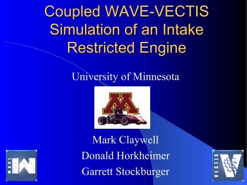
<strong>Coupled</strong> WAVE-VECTIS<br />
VECTIS<br />
<strong>Simulation</strong> <strong>of</strong> an Intake<br />
<strong>Restricted</strong> <strong>Engine</strong><br />
University <strong>of</strong> Minnesota<br />
Mark Claywell<br />
Donald Horkheimer<br />
Garrett Stockburger
University <strong>of</strong> Minnesota Formula SAE 2<br />
Agenda<br />
• Background<br />
• Project motivation<br />
• Why couple WAVE &<br />
VECTIS?<br />
• Model preparation<br />
• Comparison <strong>of</strong> two<br />
intake manifold<br />
geometries<br />
Top Feed 14,000 RPM
University <strong>of</strong> Minnesota Formula SAE 3<br />
Background<br />
• <strong>Engine</strong> is used in a small open wheeled<br />
racecar for the Formula SAE student<br />
competition.<br />
• Formula SAE dictates the use <strong>of</strong> an intake<br />
restrictor with a diameter <strong>of</strong> 20mm (with<br />
gasoline) or 19mm (with E-85).<br />
• Intake restrictor poses greatest impact and<br />
challenge to improving engine<br />
performance.<br />
Diffuser<br />
Throat<br />
Nozzle<br />
Throttle<br />
• <strong>Engine</strong> Specifications:<br />
– Four Cylinder, Four stroke<br />
– 600cc Displacement<br />
– 15,500 rpm redline<br />
– Bore = 65.5mm, Stroke = 44.5mm<br />
– 4-2-1 Exhaust Header<br />
– Sequential Port Fuel Injection (student<br />
calibrated)<br />
– DOHC, 4 valves per cylinder<br />
– Compression Ratio = 12.4:1<br />
– Fuel – Gasoline, 100 Octane
University <strong>of</strong> Minnesota Formula SAE 4<br />
Project Motivation<br />
• Effect <strong>of</strong> plenum geometry on restrictor performance.<br />
– Is there significant pressure recovery after the restrictor?<br />
– Does the plenum geometry play a role on restrictor<br />
performance?<br />
– Where to place flow bends?<br />
• Study 3D flow effects within intake manifold.<br />
• How <strong>of</strong>ten during the cycle is the flow really choked?<br />
• Achieve a better general understanding <strong>of</strong> the flow<br />
through the restrictor and intake manifold.<br />
• Improve WAVE model through pressure loss coefficients.
University <strong>of</strong> Minnesota Formula SAE 5<br />
Why Couple WAVE to VECTIS?<br />
• True 3D geometry is properly<br />
captured.<br />
• <strong>Coupled</strong> simulation avoids<br />
potentially misleading steady state<br />
CFD solutions.<br />
• Flow effects and pressure pulses are<br />
more accurately represented in their<br />
true 3D nature.<br />
Isosurface – Absolute Pressure<br />
Top Feed @ 14,000 RPM<br />
• Less empirical data gathering<br />
compared to modeling <strong>of</strong> a 1D<br />
intake geometry.<br />
• Better data visualization with CFD.<br />
• No flow separation possible in<br />
WAVE.<br />
• Better prediction <strong>of</strong> volumetric<br />
efficiency imbalances from<br />
cylinder to cylinder.
University <strong>of</strong> Minnesota Formula SAE 6<br />
WAVE – VECTIS Preparation & Run Process<br />
• Generate WAVE only model <strong>of</strong> the engine.<br />
– Run over full rpm range.<br />
• Import, Prepare, & Mesh CAD Geometry.<br />
• Link WAVE model to VECTIS using<br />
specialized external CFD orifice.<br />
• Move Fuel injector position into WAVE<br />
only portion <strong>of</strong> model.<br />
– Issue <strong>of</strong> modeling fuel spray in CFD is<br />
avoided.<br />
• Run coupled WAVE-VECTIS simulation.<br />
– Run at only one rpm point at a time.<br />
– Run multiple cycles to convergence.<br />
14,000 RPM 11,500 RPM<br />
Typical <strong>Wave</strong>-<strong>Vectis</strong> Cycle Output
Specific Challenges <strong>of</strong> Restrictor<br />
Imposed on WAVE– VECTIS Solution<br />
• High RPM & High Valve<br />
Overlap<br />
– More cycles generally<br />
required to converge as<br />
rpm increases.<br />
– High rpm <strong>of</strong> greatest<br />
interest on investigating<br />
choked restrictor flow.<br />
• In order to capture high flow velocities (supersonic) at locations with<br />
small geometry, requires…<br />
– Small time step be taken to keep Courant number reasonable even<br />
with implicit solution method.<br />
– 0.100 to .125 CAD time step at 14,000 rpm.<br />
University <strong>of</strong> Minnesota Formula SAE 7
Top/Center Feed Style Intake Manifolds<br />
Sectional View<br />
Inlet Box<br />
• Manifolds designed to differ in manifold shape only.<br />
– Same Restrictor and Inlet Geometry.<br />
– Equal Manifold Volume – between restrictor and intake<br />
runners (shaded section represents equal volumes).<br />
– Runners equal in length, diameter, and taper for both<br />
manifolds.<br />
• Both manifolds incorporate a 55° bend somewhere along the<br />
flow path.<br />
• Atmospheric inlet box, with volume = 4.1 liters.<br />
• Inlet and outlet boundaries selected where flow is<br />
predominantly one dimensional.<br />
Top Feed<br />
Top Feed – Bent Runners<br />
University <strong>of</strong> Minnesota Formula SAE 8
Volumetric Efficiency: WAVE vs. <strong>Coupled</strong><br />
University <strong>of</strong> Minnesota Formula SAE 9<br />
• Spread <strong>of</strong> volumetric efficiency values are greater with WAVE -VECTIS.<br />
• Good agreement between WAVE & WAVE-VECTIS for cylinder order and<br />
grouping <strong>of</strong> volumetric efficiencies.<br />
• Cylinder grouping: 1&4 / 2&3
Absolute Average Deviation <strong>of</strong> Volumetric Efficiency<br />
• Used as variable to assess VE spread among different<br />
manifold designs.<br />
• Better indication <strong>of</strong> VE spread than standard<br />
deviation.<br />
• WAVE-VECTIS typically shows higher AAD <strong>of</strong> VE.<br />
• Benefits <strong>of</strong> low AAD <strong>of</strong> VE<br />
– Reduced acoustical order content at intake and exhaust<br />
orifices.<br />
– Less time spent calibrating fuel and ignition changes<br />
for individual cylinders. Better overall calibration.<br />
AAD<br />
=<br />
1<br />
N<br />
N<br />
∑<br />
i=<br />
1<br />
x i<br />
− x<br />
University <strong>of</strong> Minnesota Formula SAE 10
University <strong>of</strong> Minnesota Formula SAE 11<br />
Time Averaged Data<br />
• Time averaged data used to help<br />
understand general flow<br />
characteristics <strong>of</strong> an intake.<br />
• Simplifies post-processing but<br />
introduces additional challenges.<br />
Top Feed 14,000 RPM
University <strong>of</strong> Minnesota Formula SAE 12<br />
Diffuser Flow Separation (Time Averaged)<br />
Top Feed - Post Diffuser Bend<br />
Top Feed - Bent Runners<br />
11,500<br />
RPM<br />
All scale maximums = 360 m/s<br />
14,000<br />
RPM
Peak Shear Stresses and Frictional Losses<br />
(Time Averaged)<br />
Top Feed with post diffuser bend at 14,000 RPM<br />
Top Feed with bent runners at 14,000 RPM<br />
University <strong>of</strong> Minnesota Formula SAE 13
University <strong>of</strong> Minnesota Formula SAE 14<br />
Using Shear Stress to Analyze<br />
Flow Bend Separation<br />
14,000 RPM
University <strong>of</strong> Minnesota Formula SAE 15<br />
k-ε Closure Model: Turbulence<br />
Generation Along Diffuser<br />
Throat
University <strong>of</strong> Minnesota Formula SAE 16<br />
Choked Flow Analysis <strong>of</strong> Maximum<br />
Volumetric Efficiency Potential<br />
• Maximum volumetric<br />
efficiency found by choked<br />
steady-state isentropic<br />
analysis<br />
V&<br />
choked<br />
=<br />
A<br />
*<br />
throat<br />
⎛ 2 ⎞<br />
γ ⎜ ⎟<br />
⎝ γ + 1⎠<br />
ρ<br />
0<br />
( γ + 1) ( γ −1)<br />
p ρ<br />
0<br />
0<br />
V&<br />
nom<br />
1<br />
.<br />
= * Displacement * CyclesPerSecond<br />
2<br />
V.<br />
E<br />
. max<br />
=<br />
V&<br />
V&<br />
choked<br />
nom.
University <strong>of</strong> Minnesota Formula SAE 17<br />
Mach Number Over One Cycle<br />
Near Restrictor Throat - 14,000 RPM<br />
Top Feed Intake Manifold with<br />
Post Diffuser Bend<br />
Top Feed Intake Manifold with<br />
Bent Runners<br />
• Choked ~59.7% <strong>of</strong> the cycle • Choked ~ 60.2% <strong>of</strong> the cycle<br />
• Virtually no impact on percentage <strong>of</strong> cycle choked between intake manifold geometries.<br />
• Near identical amount <strong>of</strong> supersonic flow in the diffuser. Shock-losses are <strong>of</strong> similar<br />
magnitude.
Total Pressure Drop Across Restrictor (Time Averaged)<br />
University <strong>of</strong> Minnesota Formula SAE 18<br />
• Differences in total pressure drop across restrictor did not correlate with volumetric<br />
efficiency performance <strong>of</strong> engine.<br />
• Differences in manifold geometry had
University <strong>of</strong> Minnesota Formula SAE 19<br />
Packaging and Performance<br />
Compromise<br />
Bent Runners: 100 Times Greater Re<br />
p<br />
+<br />
ρ V<br />
1 2<br />
2 2 2 2<br />
P . R.<br />
=<br />
=<br />
1 2<br />
p1<br />
+ 2 ρ1V<br />
1<br />
p<br />
p<br />
o2<br />
o1<br />
• Very little difference in pressure<br />
losses for different packaging<br />
concepts.<br />
• Bent runners should <strong>of</strong>fer better<br />
fuel targeting <strong>of</strong> valve.
Conclusions<br />
• WAVE is a very good tool by itself.<br />
– Good prediction <strong>of</strong> individual cylinder volumetric efficiency rankings<br />
even with one dimensional assumptions.<br />
– Still need WAVE to understand full rpm range intake wave dynamics<br />
and tuning effects. Quick solution times.<br />
• WAVE-VECTIS is excellent for getting a good understanding <strong>of</strong> actual<br />
pressure losses and their sources. Skin friction, turbulence generation,<br />
and separation losses can be analyzed.<br />
• Differences in intake manifold geometry had little impact on diffuser<br />
performance.<br />
• Small differences in total pressures losses did not immediately correlate<br />
to differences in engine volumetric efficiency.<br />
• Flow through restrictor is not completely choked even at 90% <strong>of</strong> engine<br />
redline.<br />
• Very small variations in engine performance for different placements <strong>of</strong><br />
flow bend to meet packaging requirements, from a flow loss standpoint.<br />
• Placement <strong>of</strong> bends can still have a large impact on intake tuning.<br />
University <strong>of</strong> Minnesota Formula SAE 20
University <strong>of</strong> Minnesota Formula SAE 21<br />
Acknowledgements<br />
• <strong>Ricardo</strong> Sponsorship and Support - Karl John,<br />
Patrick Niven, Enrico Bradamante, and Denise Rowe<br />
• University <strong>of</strong> Minnesota Supercomputer Institute -<br />
Dr. H. Birali Runesha and Support Staff<br />
• University <strong>of</strong> Minnesota SAE Chapter - Dr. Patrick Starr<br />
and Dr. David Kittleson<br />
• University <strong>of</strong> Mankato, Mechanical <strong>Engine</strong>ering -<br />
Dr. Bruce Jones
University <strong>of</strong> Minnesota Formula SAE 22<br />
Recommended Reading<br />
• Casey, M. and Wintergerste, T. (Eds.). ERCOFTAC Special Interest Group on “Quality and Trust<br />
in Industrial CFD”: Best Practice Guidelines Version 1. Brussels, Belgium: European Research<br />
Community on Flow, Turbulence and Combustion, 2000<br />
• Homann, F. “The Effect <strong>of</strong> High Viscosity on the Flow Around a Cylinder and Around A Sphere”<br />
NACA-TM-1334<br />
• Issa, R. I. “Rise <strong>of</strong> Total Pressure in Frictional Flow” AIAA Journal 1995, Vol. 33, No. 4, pp. 772-<br />
774<br />
• Pianko, M. and Wazelt, F. Suitable Averaging Techniques in Non-Uniform Internal Flow Propulsion<br />
and Energetics Panel Working Group 14, AGARD-AR-182, 1983<br />
• Roache, P. J. “Error Bars for CFD”, AIAA 2003-408<br />
• Roache, P. J. Verification and Validation in Computational Science and <strong>Engine</strong>ering. Albuquerque,<br />
NM: Hermosa Publishers. 1998<br />
• Sinclair, R., Strauss, T., and Schindler, P. “Code Coupling, a New Approach to Enhance CFD<br />
Analysis <strong>of</strong> <strong>Engine</strong>s” SAE 2000-01-0660<br />
• Gheorghiu, V., “Higher Accuracy through Combining <strong>of</strong> Quasi-3D (Instead <strong>of</strong> 1D) with True-3D<br />
Manifold Flow Models During the <strong>Simulation</strong> <strong>of</strong> ICE Gas Exchange Processes”, SAE 2001-01-1913<br />
• Wyatt, D. D. “Analysis <strong>of</strong> Errors Introduced By Several Methods <strong>of</strong> Weighting Non-Uniform Duct<br />
Flow” NACA-TN-3400, 1955<br />
• Smith, A. J. Ward, Pressure Losses in Ducted Flows, Butterworth, 1971


