Ready Bender Heron 10_10_05 - Danly (U K)
Ready Bender Heron 10_10_05 - Danly (U K)
Ready Bender Heron 10_10_05 - Danly (U K)

You also want an ePaper? Increase the reach of your titles
YUMPU automatically turns print PDFs into web optimized ePapers that Google loves.
<strong>Ready</strong> <strong>Bender</strong> <strong>Heron</strong> <strong>10</strong>_<strong>10</strong>_<strong>05</strong> <strong>10</strong>/<strong>10</strong>/<strong>05</strong> 2:37 PM Page 12<br />
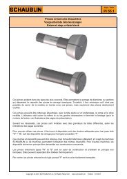
<strong>Bender</strong> Location<br />
Design Formulas<br />
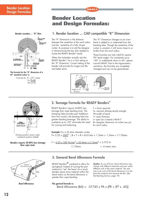
<strong>Bender</strong> Location ... “K” Dim.<br />
<strong>Bender</strong> Location<br />
and Design Formulas:<br />
1. <strong>Bender</strong> location ... CAD compatible “K” Dimension<br />
3° OVERBEND<br />
The formula for the “K” dimension of a<br />
87° standard rocker is:<br />
Formula for ‘A’ = 87°,rocker<br />
K= PT+PR<br />
Tan (A/2)<br />
The “K” Dimension is the distance<br />
between the centerline of the anvil radius<br />
and the centerline of a fully closed<br />
rocker. Its purpose is to aid the designer<br />
in dimensioning the key slots needed to<br />
locate the READY <strong>Bender</strong> ® easily.<br />
When the toolmaker actually sets the<br />
READY <strong>Bender</strong> ® , he is in fact setting to<br />
the “K” Dimension. Correct setting of the<br />
bender will provide for longer tool life<br />
and better parts.<br />
The “K” Dimension changes as an overbend<br />
is added to or subtracted from the<br />
bending lobe. Though the centerline of the<br />
rocker is constant, it will move closer to or<br />
further from the anvil radius.<br />
These formulas are only valid for square<br />
90° bend angles. For overbends up to<br />
120° or underbends down to 60°, please<br />
consult DANLY. Due to the trigonometric<br />
variations, the formulas are completely<br />
changed and can not be generalized.<br />
87°<br />
Angle A: 87°<br />
Standard<br />
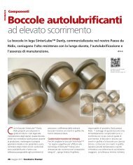
2. Tonnage Formula for READY <strong>Bender</strong>s ®<br />
T<br />
T<br />
READY <strong>Bender</strong>s ® require 50-80% less<br />
tonnage than wipe bending tools. The<br />
clamping lobe provides part holddown<br />
from first contact, the bending lobe has<br />
greater bending leverage. The ability to<br />
overbend up to 120° eliminates the need<br />
for coining and bottoming.<br />
F = force required<br />
S= nominal ultimate tensile strength<br />
W=width of bend<br />
T= stock thickness<br />
L= span (as a beam) L=B+R+T<br />
B= designer dimension of rocker (see p6)<br />
R= anvil radius<br />
(Clamp position shown solid,<br />
overbend position dotted)<br />
<strong>Bender</strong>s require 50-80% less tonnage<br />
than wipe tools.<br />
Example: For a 25.4mm diameter rocker<br />
F= 2.25 x SWT 2 ; B + T + R = 8.61mm + 1.5mm + 1.5mm = 11.76mm<br />
L<br />
F = 2.25 x 345 N/mm 2 x 25.4mm x (1.5mm) 2 = 3.772 N<br />
11.76mm<br />
= .4 metric tons<br />
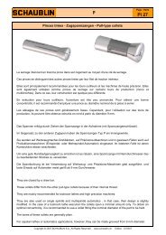
3. General Bend Allowance Formula<br />
READY <strong>Bender</strong>s ® overbend to allow for<br />
springback instead of coining the part<br />
material to “set” the bend. As a result,<br />
benders leave more material within the<br />
bend radius so the bend allowance is<br />
greater than wipe bending.<br />
Caution. As we all know, bend allowance may<br />
change with different materials and even within<br />
different coils of the same material. The only<br />
way to be sure of the bend allowance is to test<br />
bend the material and measure the BA. (See<br />
Test Bending Service, page 19).<br />
Bend Allowance<br />
The general formula is:<br />
Bend Allowance (BA) = .01745 x PA x [PR + (PT x .43)]<br />
12