
Create successful ePaper yourself
Turn your PDF publications into a flip-book with our unique Google optimized e-Paper software.
HYDROCAM ®<br />
– H1 Pump<br />
The H1 pump is aviable in six standard<br />
sizes. Each pump has four ports to activate<br />
up to four H2 units. The quality, size and<br />
stroke lenght of the H2 units hosed to each<br />
pump determines the size and oil volume<br />
of the pump needed. Pumps can be up to<br />
six feet away from H2 units.<br />
This allows you to free up critical die space<br />
and balance die loads.<br />
Piston rod travel<br />
Piston rod travel controls oil volume going<br />
to H2 unit(s). Our selection example on<br />
page 5 provides you the formulas for<br />
calculation.<br />
Multiple H2 units activated by a common<br />
pump will effect piston rod travel, find the<br />
quick select chart on page 4.<br />
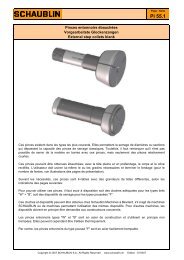
Optional stroke gauge ring<br />
Used as a visual gauge to assist in set-up.<br />
Ring is located on top pf pump boby and<br />
made to the appropriate height based upon<br />
piston rod travel calculation. This stroke<br />
gauge ring is not a stop block. See quick<br />
select chart on page 4 and calculate<br />
example on page 5 how to calculate.<br />
Mounting Suggestions:<br />
• The piston rod must always face up,<br />
perpendicular to ram/driver.<br />
Always activate piston rod with driver<br />
that is larger in diameter than the piston<br />
rod.<br />
• Driver may need to be custom ground<br />
to exact working height during<br />
HYDROCAM ® system set-up.<br />
• Locate pump higher in elevation than<br />
all H2 units it activates.<br />
• Specify hose lenght and allow for safe<br />
access from pump to H2 unit(s).<br />
Always use stop blocks.<br />
• Die storage blocks are recommended.<br />
Never store pump with piston rod<br />
depressed.<br />
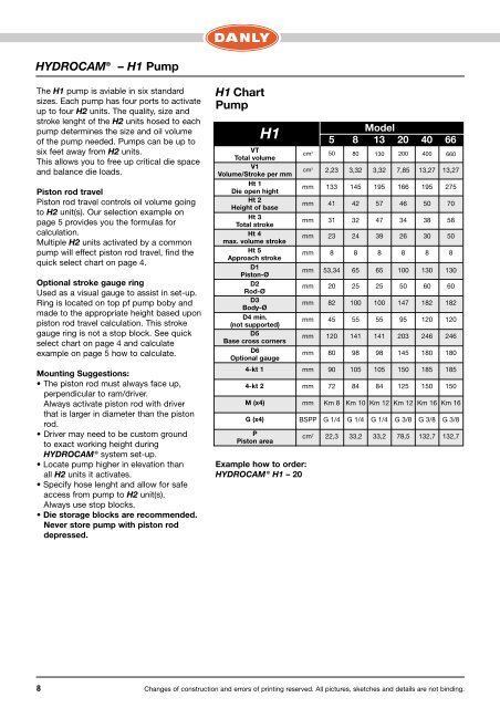
H1 Chart<br />
Pump<br />
VT<br />
Total volume<br />
V1<br />
Volume/Stroke per mm<br />
Ht 1<br />
Die open hight<br />
Ht 2<br />
Height of base<br />
Ht 3<br />
Total stroke<br />
Ht 4<br />
max. volume stroke<br />
Ht 5<br />
Approach stroke<br />
D1<br />
Piston-Ø<br />
D2<br />
Rod-Ø<br />
D3<br />
Body-Ø<br />
D4 min.<br />
(not supported)<br />
D5<br />
Base cross corners<br />
D6<br />
Optional gauge<br />
4-kt 1<br />
4-kt 2<br />
M (x4)<br />
G (x4)<br />
H1<br />
P<br />
Piston area<br />
Example how to order:<br />
HYDROCAM ® H1 – 20<br />
Model<br />
5 8 13 20 40 66<br />
cm 3 50 80 130 200 400 660<br />
cm 3 2,23 3,32 3,32 7,85 13,27 13,27<br />
mm 133 145 195 166 195 275<br />
mm 41 42 57 46 50 70<br />
mm 31 32 47 34 38 58<br />
mm 23 24 39 26 30 50<br />
mm 8 8 8 8 8 8<br />
mm 53,34 65 65 100 130 130<br />
mm 20 25 25 50 60 60<br />
mm 82 100 100 147 182 182<br />
mm 45 55 55 95 120 120<br />
mm 120 141 141 203 246 246<br />
mm 80 98 98 145 180 180<br />
mm 90 105 105 150 185 185<br />
mm 72 84 84 125 150 150<br />
mm Km 8 Km 10 Km 12 Km 12 Km 16 Km 16<br />
BSPP G 1/4 G 1/4 G 1/4 G 3/8 G 3/8 G 3/8<br />
cm 2 22,3 33,2 33,2 78,5 132,7 132,7<br />
8 Changes of construction and errors of printing reserved. All pictures, sketches and details are not binding.