GX-8000 User Maintenance Manual - RKI Instruments
GX-8000 User Maintenance Manual - RKI Instruments
GX-8000 User Maintenance Manual - RKI Instruments

Create successful ePaper yourself
Turn your PDF publications into a flip-book with our unique Google optimized e-Paper software.
H4E-0050<br />
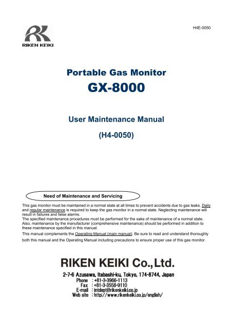
Portable Gas Monitor<br />
<strong>GX</strong>-<strong>8000</strong><br />
<strong>User</strong> <strong>Maintenance</strong> <strong>Manual</strong><br />
(H4-0050)<br />
Need of <strong>Maintenance</strong> and Servicing<br />
This gas monitor must be maintained in a normal state at all times to prevent accidents due to gas leaks. Daily<br />
and regular maintenance is required to keep the gas monitor in a normal state. Neglecting maintenance will<br />
result in failures and false alarms.<br />
The specified maintenance procedures must be performed for the sake of maintenance of a normal state.<br />
Also, maintenance by the manufacturer (comprehensive maintenance) should be performed in addition to<br />
these maintenance specified in this manual.<br />
This manual complements the Operating <strong>Manual</strong> (main manual). Be sure to read and understand thoroughly<br />
both this manual and the Operating <strong>Manual</strong> including precautions to ensure proper use of this gas monitor.
1 <strong>Maintenance</strong> Intervals and Items<br />
1<br />
<strong>Maintenance</strong> Intervals and<br />
Items<br />
• Daily maintenance: Perform maintenance before beginning to work.<br />
• Monthly maintenance: Perform alarm test once a month.<br />
• Regular maintenance: Perform a maintenance once or more for every six months to maintain the<br />
performance as a safety unit.<br />
<strong>Maintenance</strong><br />
item<br />
Battery level<br />
check<br />
Concentration<br />
display check<br />
Flow rate check<br />
<strong>Maintenance</strong> content<br />
Daily<br />
maintenance<br />
Monthly<br />
maintenance<br />
Regular<br />
maintenance<br />
Check that the battery level is sufficient. ◦ ◦ ◦<br />
Make the gas monitor draw in fresh air. Check<br />
that the concentration display value is zero (or<br />
20.9 vol% on the oxygen deficiency meter).<br />
When the reading is incorrect, perform the zero<br />
adjustment (fresh air adjustment) after ensuring<br />
that no other gases exist around it.<br />
See the flow rate indicator to check for<br />
abnormalities.<br />
◦ ◦ ◦<br />
◦ ◦ ◦<br />
Filter check Check the dust filter for dust or clogging. ◦ ◦ ◦<br />
Alarm test<br />
Span adjustment<br />
Check the alarm lamp and buzzer for normal<br />
operation by using the alarm test function.<br />
Perform the span adjustment by using the<br />
calibration gas.<br />
◦ ◦<br />
Gas alarm check Check the gas alarm by using the calibration gas. ◦<br />
◦<br />
<strong>GX</strong>-<strong>8000</strong> - 2 -
2 Regular <strong>Maintenance</strong> Mode<br />
2<br />
Regular <strong>Maintenance</strong> Mode<br />
Regular maintenance mode is an operation (adjustment) mode in which span adjustment and setup such as<br />
change of alarm setpoints can be performed.<br />
WARNING<br />
After the adjustment is completed, do not forget to return to the detection mode.<br />
(If the gas monitor remains in the regular maintenance mode, it does not automatically return to the<br />
detection mode.)<br />
The regular maintenance mode comes in two types: Calibration and maintenance modes. To enter the<br />
calibration mode, press the DISPLAY switch with the switch pressed in the detection mode and release<br />
them when the buzzer sounds. To enter the maintenance mode, press the POWER switch with the and<br />
switches pressed at power-on and release them when the buzzer sounds. The maintenance mode is<br />
password-protected. The input of a password is needed in the beginning.<br />
- 3 - <strong>GX</strong>-<strong>8000</strong>
2 Regular <strong>Maintenance</strong> Mode<br />
The regular maintenance mode has the menus shown below.<br />
Mode Item LCD display Details<br />
Calibration Fresh air adjustment AIR CAL Perform the fresh air adjustment. *<br />
mode Zero adjustment for<br />
high-concentration<br />
combustible gases<br />
VOLZ.CAL Perform the zero adjustment for<br />
high-concentration combustible<br />
gases.<br />
<strong>Maintenance</strong><br />
mode<br />
Simultaneous span<br />
adjustment for all channels<br />
Span adjustment for each<br />
channel<br />
AUTO CAL<br />
ONE CAL<br />
Perform the span adjustment<br />
simultaneously for all channels.<br />
Perform the span adjustment for<br />
each channel.<br />
Bump test BUMP Perform the bump test. **<br />
Exit calibration mode NORMAL Exit the calibration mode and **<br />
return to the detection mode.<br />
Date/time setting DATE Set the date and time.<br />
Fresh air adjustment AIR CAL Perform the fresh air adjustment. *<br />
Zero adjustment for VOL Z.CAL Perform the zero adjustment for<br />
high-concentration<br />
high-concentration combustible<br />
combustible gases<br />
gases.<br />
Simultaneous span<br />
adjustment for all channels<br />
Span adjustment for each<br />
channel<br />
AUTO CAL<br />
ONE CAL<br />
Perform the span adjustment<br />
simultaneously for all channels.<br />
Perform the span adjustment for<br />
each channel.<br />
Bump test BUMP Perform the bump test. ***<br />
Alarm setting ALARM-P Change the alarm setpoint value.<br />
Bump test setting BUMP-SET Set the bump test. ***<br />
Beep setting BEEP SET Set the confirmation beep<br />
operation.<br />
***<br />
Exit maintenance mode START Exit the maintenance mode and<br />
enter the detection mode.<br />
* mark indicates items that can be operated (adjusted) in other modes such as<br />
[Detection mode] than the regular maintenance mode. Note that operation can<br />
be performed in any mode.<br />
** mark indicates the menus in the calibration modes available in the overseas<br />
specification: AUTO CAL, ONE CAL, BUMP, and NORMAL.<br />
*** mark indicates the items not available in the Japanese specifications.<br />
NOTE<br />
If any mode that is not described in this manual or Operating <strong>Manual</strong> (main manual) (any mode but the regular<br />
maintenance mode) is entered by mistake, turn off the power once and try again.<br />
**<br />
**<br />
<strong>GX</strong>-<strong>8000</strong> - 4 -
2 Regular <strong>Maintenance</strong> Mode<br />
<br />
In the detection mode, keep pressed and press<br />
the DISPLAY switch. When the buzzer beeps,<br />
release the switches.<br />
Calibration mode<br />
AIR CAL<br />
Perform the fresh air adjustment.<br />
Fresh air<br />
adjustment<br />
=> P16<br />
VOLZ.CAL<br />
Perform the zero adjustment for<br />
high-concentration combustible gases.<br />
AUTO CAL<br />
Perform the span adjustment simultaneously for all<br />
channels.<br />
(Set the span gas concentration in advance and<br />
make adjustment at once.)<br />
Zero adjustment<br />
for highconcentration<br />
combustible<br />
gases<br />
=> P20<br />
Simultaneous<br />
span adjustment<br />
for all channels<br />
=> P18<br />
ONE CAL<br />
Perform the span adjustment for each channel.<br />
(While gas is supplied, perform span adjustment<br />
using UP/DOWN.)<br />
Span adjustment<br />
for each channel<br />
=> P19<br />
BUMP<br />
Perform the bump test.<br />
Bump test<br />
=> P6<br />
NORMAL<br />
Exit the calibration mode.<br />
Detection mode<br />
- 5 - <strong>GX</strong>-<strong>8000</strong>
2 Regular <strong>Maintenance</strong> Mode<br />
<br />
Required equipment/material<br />
• Bump test gas (collected in a gas sampling bag)<br />
Connection<br />
Connect the equipment as shown below to perform the bump test.<br />
Gas sampling probe<br />
(with a tube)<br />
GAS IN<br />
Gas<br />
sampling<br />
bag<br />
GAS OUT<br />
(Open)<br />
<strong>GX</strong>-<strong>8000</strong><br />
main unit<br />
WARNING<br />
About the bump test gas<br />
The bump test gas is a hazardous gas (toxic, oxygen deficient, etc.). Handle the gas and related jigs and<br />
tools with due care (e.g., the gas must not be inhaled or the gas sampling bag must not have any hole).<br />
About the place for span adjustment<br />
• Perform span adjustment where no silicon, organic solvent, spray can gases, etc. are used.<br />
• Perform span adjustment indoors at normal temperature without remarkable fluctuation (within ±5°C).<br />
• Perform span adjustment in an exhaust booth.<br />
CAUTION<br />
The GAS OUT side of the pipe must be left open without any pipe connected. A supplied gas must be<br />
discharged to a safe place.<br />
<strong>GX</strong>-<strong>8000</strong> - 6 -
2 Regular <strong>Maintenance</strong> Mode<br />
BUMP<br />
Press the ENTER switch.<br />
The bump test gas concentration is displayed.<br />
The concentration of the prepared test gas<br />
must be consistent with the displayed test gas<br />
concentration.<br />
To change the test gas concentration value,<br />
change the value in span adjustment menu.<br />
The test gas concentration is set to the same<br />
value as the span gas concentration.<br />
Simultaneous span adjustment for all channels<br />
=> P18<br />
Supply the test gas and press ENTER.<br />
BUMP and APPLY are displayed alternately,<br />
and the countdown is started.<br />
Supply the<br />
test gas.<br />
NOTE<br />
Only on TYPE-A and TYPE-E,<br />
every time the or switch<br />
is pressed, the concentration<br />
of the span gas for<br />
high-concentration<br />
combustible gases is<br />
displayed alternately.<br />
Go to (1) if all the<br />
channels are Pass in<br />
about 30 seconds.<br />
Go to (2) if any of the<br />
channels is Fail.<br />
(1)<br />
<br />
The result is displayed in about 30 seconds.<br />
Stop supplying the gas.<br />
The results and values are displayed<br />
alternately every time the or switch is<br />
pressed.<br />
P: Pass, F: Fail<br />
After checking the result, press ENTER. The<br />
gas monitor returns to the calibration mode<br />
menu.<br />
Return to BUMP.<br />
Stop supplying<br />
the test gas.<br />
- 7 - <strong>GX</strong>-<strong>8000</strong>
2 Regular <strong>Maintenance</strong> Mode<br />
(2)<br />
Continue<br />
supplying the<br />
test gas.<br />
<br />
Continue supplying the gas. The result is not<br />
displayed, and the span adjustment is<br />
automatically started. CAL and APPLY are<br />
displayed alternately, and the countdown is<br />
started.<br />
The span adjustment is started in about 30<br />
seconds, and the result is displayed. Left: Test<br />
result, Right: Adjustment result (P: Pass, F:<br />
Fail)<br />
The results (P or F) bump test result<br />
values span adjustment result values are<br />
displayed alternately every time the or <br />
switch is pressed. Stop supplying the gas.<br />
After checking the result, press ENTER. The<br />
gas monitor returns to the calibration mode<br />
menu.<br />
Return to BUMP.<br />
Stop supplying<br />
the test gas.<br />
NOTE<br />
If "F" (Fail) is displayed after the span adjustment, replace the sensor with a new one.<br />
<strong>GX</strong>-<strong>8000</strong> - 8 -
2 Regular <strong>Maintenance</strong> Mode<br />
<br />
The maintenance mode includes setting menus which are usually not used. Be careful not to change these<br />
settings by mistake. It is recommended that setting changes should be recorded in a log.<br />
Keep the and switches pressed and<br />
press the POWER switch. When the buzzer<br />
beeps, release the switches.<br />
The input field blinks. Press the or switch<br />
to select a number and press ENTER to<br />
confirm it. Enter four digits from the left.<br />
Password: 0008<br />
Regular maintenance mode<br />
DATE<br />
Set the date and time.<br />
Date/time setting<br />
=> P11<br />
AIR CAL<br />
Perform the fresh air adjustment.<br />
Fresh air<br />
adjustment<br />
=> P16<br />
VOL Z.CAL<br />
Perform the zero adjustment for<br />
high-concentration combustible gases.<br />
AUTO CAL<br />
Perform the span adjustment simultaneously<br />
for all channels.<br />
(Set the span gas concentration in advance<br />
and make adjustment at once.)<br />
Zero adjustment<br />
for highconcentration<br />
combustible<br />
gases<br />
=> P20<br />
Simultaneous<br />
span adjustment<br />
for all channels<br />
=> P18<br />
ONE CAL<br />
Perform the span adjustment for each channel.<br />
(While gas is supplied, perform span<br />
adjustment using UP/DOWN.)<br />
Span adjustment<br />
for each channel<br />
=> P19<br />
- 9 - <strong>GX</strong>-<strong>8000</strong>
2 Regular <strong>Maintenance</strong> Mode<br />
BUMP<br />
Perform the bump test.<br />
Bump test<br />
=> P6<br />
ALARM-P<br />
Set the alarm setpoint.<br />
Alarm setpoint<br />
setting<br />
=> P12<br />
BUMP-SET<br />
Set the bump test.<br />
Bump test<br />
settings<br />
=> P13<br />
BEEP SET<br />
Set whether or not to perform the confirmation<br />
beep operation.<br />
Press the or switch to select ON or OFF<br />
and press the ENTER switch to confirm it.<br />
START<br />
Exit the maintenance mode.<br />
Press ENTER to<br />
enter the<br />
detection mode.<br />
<strong>GX</strong>-<strong>8000</strong> - 10 -
2 Regular <strong>Maintenance</strong> Mode<br />
<br />
Set the date/time.<br />
DATE<br />
Press the ENTER switch.<br />
The input field blinks. Enter the year, month, day,<br />
hour, and minute in this order. Press the or <br />
switch to adjust the date and time and press the<br />
ENTER switch to enter it.<br />
(The figure on the right shows an example of<br />
input for 2011/01/07 19:32.)<br />
As soon as the last part (minute) is entered, the<br />
date/time setting is confirmed. After END is<br />
displayed, the gas monitor automatically returns<br />
to the maintenance mode menu.<br />
Return to DATE.<br />
- 11 - <strong>GX</strong>-<strong>8000</strong>
2 Regular <strong>Maintenance</strong> Mode<br />
<br />
Set the alarm setpoint.<br />
ALARM-P<br />
Press the ENTER switch.<br />
The alarm setpoint setting selection menu is<br />
displayed.<br />
Press the or switch to display a target gas for<br />
which the alarm setpoint should be set. Every time<br />
the or switch is pressed, the target gas is<br />
changed (in the order of Combustible, O2, H2S, CO,<br />
and ESCAPE).<br />
While a desired target gas is selected, press the<br />
Enter switch to cause the alarm setpoint display<br />
to blink, prompting for input.<br />
Press the or switch to change an alarm setpoint<br />
value. Next, press the ENTER switch to enter it.<br />
Continue to set WARNING, ALARM, STEL, and TWA<br />
in this order. (Set the STEL and TWA alarms only for<br />
CO and H 2 S.)<br />
Change the last item and press the ENTER switch.<br />
After the changed settings are confirmed and END is<br />
displayed, the gas monitor automatically returns to<br />
the alarm setpoint setting selection menu (*). Repeat<br />
the same procedure to set other target gases.<br />
When the alarm setpoint setting is completed, press<br />
the or switch until ESCAPE is displayed. Press<br />
the ENTER switch to return to the maintenance mode<br />
menu.<br />
Return to ALARM-P.<br />
<strong>GX</strong>-<strong>8000</strong> - 12 -
2 Regular <strong>Maintenance</strong> Mode<br />
<br />
Check and set the setting items related to the bump test.<br />
BUMP-SET<br />
Press the ENTER switch.<br />
Press the or switch to display a target setting<br />
item to be checked or set.<br />
The test time is displayed.<br />
Press the ENTER switch. The numeric display<br />
blinks, prompting for input. Press the or switch<br />
to enter introduction time. Press the ENTER switch<br />
to confirm it. The figure on the right shows an<br />
example of 30 seconds.<br />
(Test time: 30, 45, 60, or 90 seconds)<br />
The test pass tolerance range is displayed.<br />
Press the ENTER switch. The numeric display blinks,<br />
prompting for input. Press the or switch to enter<br />
a range. Press the ENTER switch to confirm it.<br />
The figure on the right shows an example of range<br />
within ±30%.<br />
(Pass range: Within ±10%, ±20%, ±30%, ±40%, or<br />
±50%)<br />
The adjustment time after test fail is displayed.<br />
Press the ENTER switch. The numeric display blinks,<br />
prompting for input. Press the or switch to enter<br />
adjustment time. Press the ENTER switch to confirm<br />
it. The figure on the right shows an example of 60<br />
seconds.<br />
Whether or not to enable automatic adjustment after<br />
test fail is displayed.<br />
Press the ENTER switch. The ON (OFF) display<br />
blinks, prompting for input. Press the or switch<br />
to select ON or OFF. Next, press the ENTER switch<br />
to confirm it. ON: Automatic adjustment enabled<br />
OFF:Automatic adjustment disabled The figure on<br />
the right shows an example of ON setting.<br />
When the setting is completed, press the or <br />
switch until ESCAPE is displayed. Press the ENTER<br />
switch to return to the maintenance mode menu.<br />
Return to BUMP-SET.<br />
- 13 - <strong>GX</strong>-<strong>8000</strong>
3 Span Adjustment 3-1. Preparation for span adjustment<br />
3<br />
Span Adjustment<br />
3-1. Preparation for span adjustment<br />
Required equipment/material<br />
• Zero adjustment gas for high-concentration combustible gases (collected in a gas sampling bag)<br />
• Span adjustment gas (collected in a gas sampling bag)<br />
• Stopwatch<br />
Connection<br />
Connect the equipment as shown below to perform the span adjustment.<br />
Gas sampling probe<br />
(with a tube)<br />
GAS IN<br />
Gas<br />
sampling<br />
bag<br />
GAS OUT<br />
(Open)<br />
<strong>GX</strong>-<strong>8000</strong><br />
main unit<br />
WARNING<br />
About the span adjustment gas<br />
The span adjustment gas is a hazardous gas (toxic, oxygen deficient, etc.). Handle the gas and<br />
related jigs and tools with due care (e.g., the gas must not be inhaled or the gas sampling bag must<br />
not have any hole).<br />
About the place for span adjustment<br />
• Perform span adjustment where no silicon, organic solvent, spray can gases, etc. are used.<br />
• Perform span adjustment indoors at normal temperature without remarkable fluctuation (within ±5°C).<br />
• Perform span adjustment in an exhaust booth.<br />
CAUTION<br />
The GAS OUT side of the pipe must be left open without any pipe connected. A supplied gas must be<br />
discharged to a safe place.<br />
<strong>GX</strong>-<strong>8000</strong> - 14 -
3-1. Preparation for span adjustment 3 Span Adjustment<br />
<br />
Perform adjustment using the procedure shown below.<br />
(1) Fresh air adjustment (AIR CAL) *1<br />
Warm up the gas monitor for 60 minutes or longer before performing the fresh air<br />
adjustment to ensure more accurate adjustment.<br />
(2) Span adjustment (AUTO CAL or ONE CAL) *1<br />
The gases may be introduced in random order.<br />
• Combustible gas (%LEL)<br />
• O 2 gas *1<br />
• CO gas<br />
• H 2 S gas<br />
(3) Zero adjustment for high-concentration combustible gases (VOL Z.CAL) (only TYPE-A, E) *1<br />
• N 2 gas<br />
(4) Span adjustment for high-concentration combustible gases (AUTO CAL or ONE CAL) (only<br />
TYPE-A, E) *1<br />
• Combustible gas (vol%)<br />
End of span adjustment<br />
WARNING<br />
When the fresh air adjustment is performed in the atmosphere, check the atmosphere for freshness<br />
before beginning the adjustment. If other gases exist, the adjustment cannot be performed properly,<br />
thus leading to dangers when the gas leaks.<br />
CAUTION<br />
Only Type-A, E<br />
*1 Perform adjustment in the following order: "fresh air adjustment, span adjustment, zero adjustment<br />
for high-concentration combustible gases, and span adjustment for high-concentration combustible<br />
gases.<br />
The sensor for high-concentration combustible gases has different outputs depending on whether the<br />
base gas is air or N2. Performing adjustment in any different order than the above adversely<br />
influences the reading taken when a combustible gas (vol%) is drawn in.<br />
NOTE<br />
Before starting the adjustment, let the gas monitor draw the gas and wait until the readings are stabilized.<br />
- 15 - <strong>GX</strong>-<strong>8000</strong>
3 Span Adjustment 3-2. Fresh air adjustment<br />
3-2. Fresh air adjustment<br />
WARNING<br />
When the fresh air adjustment is performed in the atmosphere, check the atmosphere for freshness<br />
before beginning the adjustment. If other gases exist, the adjustment cannot be performed properly,<br />
thus leading to dangers when the gas leaks.<br />
NOTE<br />
If the existence of other gases in the atmosphere is suspected before performing the fresh air adjustment,<br />
collect fresh air in the gas sampling bag and perform the adjustment using a gas supply adapter in the same<br />
way as for the span adjustment.<br />
<strong>GX</strong>-<strong>8000</strong> - 16 -
3-2. Fresh air adjustment 3 Span Adjustment<br />
AIR CAL<br />
Press the ENTER switch.<br />
The current concentration readings of the gases are<br />
displayed. Press the AIR switch when they are<br />
stabilized.<br />
When the AIR switch is pressed, HOLD AIR is<br />
displayed. Keep pressing the switch until RELEASE<br />
is displayed.<br />
Release the AIR switch.<br />
* Only on TYPE-A and TYPE-E, a 30-second<br />
countdown is started. No countdown is started on<br />
other types.<br />
After the fresh air adjustment is successfully<br />
completed and END is displayed, the gas monitor<br />
automatically returns to the menu.<br />
Return to AIR CAL.<br />
- 17 - <strong>GX</strong>-<strong>8000</strong>
3 Span Adjustment 3-3. Span adjustment<br />
3-3. Span adjustment<br />
<br />
AUTO CAL<br />
Press the ENTER switch.<br />
The span gas concentration is displayed.<br />
It needs to be consistent with the concentration of<br />
the prepared span gas. To change the value, press<br />
the and DISPLAY switches simultaneously.<br />
The span gas concentration setting menu is<br />
displayed.<br />
Press the or switch to display a target gas for<br />
which the span gas concentration should be<br />
changed. Every time AIR is pressed, the target gas<br />
is changed (in the order of Combustible, O2, H2S,<br />
CO, and ESCAPE).<br />
<br />
[Setting repeated for each gas]<br />
While a desired target gas is selected, press the<br />
ENTER switch to cause the span gas<br />
concentration display to blink, prompting for input.<br />
Press the or switch to change the span gas<br />
concentration setting.<br />
After the ENTER switch is pressed to confirm the<br />
changed setting and END is displayed, the gas<br />
monitor automatically returns to the span gas<br />
concentration setting menu. Repeat the same<br />
procedure to set other target gases.<br />
When all of the span gas concentration setting is<br />
completed, press the ▲ or ▼ switch until<br />
ESCAPE is displayed. Press ENTER to return to<br />
the original screen.<br />
While the span gas concentration is displayed,<br />
press the MODE switch to cause AUTO CAL to<br />
blink and display the current concentration<br />
readings (prompting for supply). Prepare and<br />
supply the span gas.<br />
NOTE<br />
The changed value is saved.<br />
From next time, the changed<br />
value is displayed in the<br />
beginning.<br />
Supply the span<br />
gas.<br />
In 60 seconds after supplying the span gas when<br />
the readings are stabilized, press the ENTER<br />
switch to perform adjustment.<br />
After the adjustment is successfully completed and<br />
PASS is displayed, the gas monitor automatically<br />
returns to the menu. Stop supplying the gas.<br />
Return to AIR CAL.<br />
Stop supplying<br />
the span gas.<br />
<strong>GX</strong>-<strong>8000</strong> - 18 -
3-3. Span adjustment 3 Span Adjustment<br />
<br />
ONE CAL<br />
Press the ENTER switch.<br />
The span adjustment selection menu is displayed.<br />
Press the or switch to display a target gas for<br />
which the span adjustment should be performed.<br />
Every time the or switch is pressed, the target<br />
gas is changed (in the order of Combustible, O2,<br />
H2S, CO, and ESCAPE).<br />
While a desired target gas is selected, press the<br />
ENTER switch to cause the concentration display to<br />
blink and display the current concentration readings<br />
(prompting for supply). Prepare and supply the span<br />
gas.<br />
Supply the span<br />
gas.<br />
In 60 seconds after supplying the span gas when the<br />
readings are stabilized, press the or switch to<br />
adjust to the gas concentration.<br />
Press the ENTER switch to adjust it.<br />
After END is displayed, the gas monitor automatically<br />
returns to the span adjustment for each channel<br />
menu (*). Stop supplying the gas.<br />
Repeat the same procedure to adjust other target<br />
gases.<br />
Stop supplying<br />
the span gas.<br />
When all of the span adjustment is completed, press<br />
the or switch until ESCAPE is displayed.<br />
Press the ENTER switch to return to the menu.<br />
Return to ONE CAL.<br />
- 19 - <strong>GX</strong>-<strong>8000</strong>
3 Span Adjustment 3-3. Span adjustment<br />
(Only TYPE-A, E)<br />
VOL Z.CAL<br />
Press the ENTER switch.<br />
The VOL Z.CAL display blinks. Until the combustible<br />
gas range switches to VOL%, the combustible gas<br />
concentration is displayed as ---.<br />
The current concentration readings of the<br />
combustible gas and oxygen are displayed<br />
(prompting for supply). Prepare and supply the zero<br />
gas.<br />
Supply the zero<br />
gas.<br />
In about 60 seconds after supplying the zero gas<br />
when the readings are stabilized, press the ENTER<br />
switch to perform adjustment.<br />
After the zero adjustment is successfully completed<br />
and END is displayed, the gas monitor automatically<br />
returns to the menu.<br />
Return to VOL Z.CAL<br />
Stop supplying<br />
the zero gas.<br />
<strong>GX</strong>-<strong>8000</strong> - 20 -
4 Replacement of Consumable Parts<br />
4<br />
Replacement of<br />
Consumable Parts<br />
<br />
(1) Loosen the four screws on the sensor cover and remove the sensor cover.<br />
(2) Remove the sensor rubber seal.<br />
Take care not to damage the sensor rubber seal and the seal surface inside the sensor cover that<br />
comes into contact with the rubber seal.<br />
Sensor<br />
cover<br />
Captive screws<br />
(four)<br />
Sensor rubber seal<br />
Peel it off if it sticks to the sensor<br />
cover.<br />
(3) Replace the sensor.<br />
Pay attention to the installation direction of the sensors.<br />
Check that the pins of the sensors are inserted firmly all the way (that the sensors have equal heights).<br />
Also, replace the rubber seals as required.<br />
Handle the rubber seals with care because any damage on them will impair the waterproof property.<br />
H 2 S sensor<br />
O 2 sensor<br />
NC (%LEL) sensor<br />
CO sensor<br />
TE(vol%) sensor<br />
<strong>GX</strong>-<strong>8000</strong> - 21 -
4 Replacement of Consumable Parts<br />
(4) Using an opposite procedure to the above, install the sensor rubber seal and fix the sensor cover.<br />
Screw tightening torque: 5 to 5.5 kgf・cm (49 to 54 N・cm)<br />
Sensor<br />
rubber seal<br />
Install the rubber seal<br />
so that the concave<br />
part covers the sensor.<br />
Install the sensor cover<br />
horizontally so as not<br />
to warp the sensor<br />
rubber seal.<br />
Sensor<br />
<br />
For the stable operation of the gas monitor and safety, a qualified service engineer is required to take care<br />
of replacement of the parts that requires high expertise. Please contact RIKEN KEIKI.<br />
<strong>GX</strong>-<strong>8000</strong> - 22 -
Warranty Policy<br />
RIKEN KEIKI CO., LTD., warrants gas alarm equipment sold by us to be free from defects in materials,<br />
workmanship, and performance for a period of one year from date of shipment from RIKEN KEIKI CO., LTD.,<br />
Inc. Any parts found defective within that period will be repaired or replaced, at our option, free of charge.<br />
This warranty does not apply to those items which by their nature are subject to deterioration or<br />
consumption in normal service, and which must be cleaned, repaired, or replaced on a routine basis.<br />
Warranty is voided by abuse including mechanical damage, alteration, rough handling, or repair procedures<br />
not in accordance with the operator’s manual. This warranty indicates the full extent of our liability, and we<br />
are not responsible for removal or replacement costs, local repair costs, transportation costs, or contingent<br />
expenses incurred without our prior approval.<br />
THIS WARRANTY IS EXPRESSLY IN LIEU OF ANY AND ALL OTHER WARRANTIES AND<br />
REPRESENTATIONS, EXPRESSED OR IMPLIED, AND ALL OTHER OBLIGATIONS OR LIABILITIES<br />
ON THE PART OF RIKEN KEIKI CO., LTD., INCLUDING BUT NOT LIMITED TO, THE WARRANTY OF<br />
MERCHANTABILITY OR FITNESS FOR A PARTICULAR PURPOSE. IN NO EVENT SHALL RIKEN<br />
KEIKI CO., LTD., BE LIABLE FOR INDIRECT, INCIDENTAL, OR CONSEQUENTIAL LOSS OR<br />
DAMAGE OF ANY KIND CONNECTED WITH THE USE OF ITS PRODUCTS OR FAILURE OF ITS<br />
PRODUCTS TO FUNCTION OR OPERATE PROPERLY.<br />
This warranty covers instruments and parts sold to users by authorized distributors, dealers, and<br />
representatives as appointed by RIKEN KEIKI CO., LTD.<br />
We do not assume indemnification for any accident or damage caused by the operation of this gas monitor,<br />
and our warranty is limited to the replacement of parts or our complete goods.<br />
- 23 - <strong>GX</strong>-<strong>8000</strong>