Bioscreening, Biophotonics, and Micromanipulation - Research ...
Bioscreening, Biophotonics, and Micromanipulation - Research ...
Bioscreening, Biophotonics, and Micromanipulation - Research ...

Create successful ePaper yourself
Turn your PDF publications into a flip-book with our unique Google optimized e-Paper software.
Chapter 12. <strong>Bioscreening</strong>, <strong>Biophotonics</strong>, <strong>and</strong> <strong>Micromanipulation</strong><br />
<strong>Bioscreening</strong>, <strong>Biophotonics</strong>, <strong>and</strong> <strong>Micromanipulation</strong><br />
Academic <strong>and</strong> <strong>Research</strong> Staff<br />
Prof. Mehmet Fatih Yanik<br />
<strong>Research</strong> Affiliates<br />
Dr. Fei Zeng<br />
Graduate Students<br />
Christopher Rohde, Matthew Angel, Ricardo Gonzalez, Mark Scott, Zachary Wisner-Gross,<br />
Naiyan Chen, Peter Chiarelli, Billy Putnams<br />
Undergraduate Students<br />
Cankutan Hasar, Albert Lee, Am<strong>and</strong>a D. Gaudreau<br />
Sponsors: MIT, RLE, NIH Director’s New Innovator Award, US Air Force - Lincoln Laboratory,<br />
David <strong>and</strong> Lucille Packard Foundation.<br />
We are a new group established in September 2006. The recent facilities we built are an<br />
optics/microfluidics laboratory including custom-made femtosecond laser microsurgery, twophoton<br />
imaging <strong>and</strong> optical tweezer technologies, microfluidic instrumentation <strong>and</strong> research<br />
microscopes; a wet lab for molecular biology, polymer chemistry, <strong>and</strong> microfluidic assembly; <strong>and</strong><br />
a tissue room for culturing cell lines, primary neurons as well as embryonic stem cell derived<br />
neurons.<br />
Project 1. On-chip High-throughput Small-Animal Screening Technology<br />
The goal of this project is to develop high-throughput technologies to perform genome-wide<br />
genetic <strong>and</strong> drug screens on the small-animal model called C. elegans.<br />
Existing large vertebrate animal models currently cannot be used in high-throughput assays for<br />
rapid identification of new genes <strong>and</strong> drug targets because of the size <strong>and</strong> complexity of the<br />
instrumentation with which these models are studied. In recent years, the advantages of using<br />
small invertebrate animals as model systems for human disease have become increasingly<br />
apparent, <strong>and</strong> have resulted in two Nobel Prizes in Physiology <strong>and</strong> Medicine during the last five<br />
years for studies conducted on the nematode C. elegans. The availability of a wide array of<br />
species-specific genetic techniques, along with the worm’s transparency, <strong>and</strong> its ability to grow in<br />
minute volumes make C. elegans an extremely powerful model organism.<br />
However, since the first studies on C. elegans in the early 1960s, little has changed in how<br />
scientists manipulate this tiny organism by manually picking, sorting, <strong>and</strong> transferring individual<br />
worms. As a result, large-scale assays such as mutagenesis <strong>and</strong> RNAi screens (1-3) can take<br />
months or even years to complete manually. Currently, high-throughput C. elegans assays are<br />
performed by adapting techniques developed for screening cell lines, such as flow-through<br />
sorters <strong>and</strong> microplate readers (4-6). Due to the significant limitations of these methods, highthroughput<br />
small-animal studies either have to be dramatically simplified before they can be<br />
automated or cannot be conducted at all.<br />
We recently developed the key components of the first integrated, whole-animal, high-throughput<br />
sorting <strong>and</strong> large-scale screening platform for drug <strong>and</strong> genetic assays with sub-cellular<br />
resolution using microfluidic devices. Although microfluidics have previously been used to<br />
perform novel assays on C. elegans, so far research has been limited to specific applications<br />
such as generation of oxygen gradients (7), worm culturing/monitoring during spaceflight (8),<br />
optofluidic imaging (9) <strong>and</strong> maze exploration (10). We have designed three microfluidic devices<br />
12-1
Chapter 12. <strong>Bioscreening</strong>, <strong>Biophotonics</strong>, <strong>and</strong> <strong>Micromanipulation</strong><br />
that can be combined in various configurations to allow a multitude of complex high-throughput<br />
assays: 1. a small-animal sorter for sorting live animals according to sub-cellular features, 2. an<br />
array of microfluidic chambers for simultaneous incubation, immobilization, sub-cellular-resolution<br />
imaging <strong>and</strong> independent screening of many animals on a single chip, <strong>and</strong> 3. a microfluidic<br />
interface to large-scale multi-well-format libraries that also functions as a multiplexed animal<br />
dispenser.<br />
The microfluidic devices that we fabricated consist of flow <strong>and</strong> control layers made from flexible<br />
polymers (11). The flow-layers contain micro-channels for manipulating C. elegans, immobilizing<br />
them for imaging, <strong>and</strong> delivery of media <strong>and</strong> reagents. The flow-layers also contain microchambers<br />
for incubating the animals. The control-layers consist of micro-channels that when<br />
pressurized, flex a membrane into the flow channels, blocking or redirecting the flow (12).<br />
Animals in the flow lines can be imaged through a transparent glass substrate.<br />
On-Chip High-Throughput Sorting<br />
inlet<br />
suction<br />
C<br />
A<br />
B<br />
E<br />
F<br />
collection<br />
D<br />
circulator<br />
wash<br />
suction<br />
waste/circulator<br />
Steps<br />
A<br />
B<br />
C<br />
D<br />
E<br />
F<br />
Valve Cross-Section<br />
1 (clean)<br />
0<br />
1<br />
0<br />
0<br />
1<br />
0<br />
flow<br />
control<br />
glass<br />
open (1) closed (0)<br />
2 (capture)<br />
3 (wash)<br />
4 (isolate)<br />
5 (immobilize)<br />
1<br />
0<br />
0<br />
0<br />
0<br />
1<br />
1<br />
1<br />
1<br />
1<br />
1<br />
0<br />
0<br />
0<br />
1<br />
1<br />
1<br />
1<br />
0<br />
0<br />
0<br />
0<br />
0<br />
0<br />
6 (collect)<br />
0<br />
1<br />
0<br />
0<br />
1/0<br />
0/1<br />
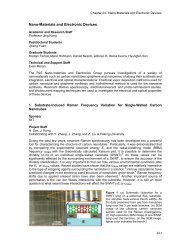
Fig 1. Microfluidic worm-sorter layout <strong>and</strong> operation. The sorter consists of control channels <strong>and</strong> valves<br />
(grey) that direct the flow of worms in the flow channels in different directions. The valves are labeled with<br />
the letters “A” through “F” in the layout, <strong>and</strong> the actuation order of valves is listed in the table. A value of 1<br />
represents an open valve, while a value of 0 represents a closed valve, as illustrated in the bottom-left box.<br />
The steps taken to sort each worm are as follows: “CLEAN”: The immobilization chamber is cleaned,<br />
“CAPTURE”: A worm is captured in the chamber by suction via the top channel while the lower suction<br />
channels are inactive, “WASH”: The chamber is washed to flush any other worms in the chamber (blue line)<br />
towards the waste or the circulator, “ISOLATE”: The chamber is isolated from all of the channels,<br />
“IMMOBILIZE”: The worm is released from the top suction channel, <strong>and</strong> is restrained by the lower suction<br />
channels, The image acquisition <strong>and</strong> processing are performed, “COLLECT”: The worm is either collected or<br />
directed to the waste, depending on its phenotype.<br />
Sorters enable rapid selection of organisms with phenotypes of interest for a variety of assays<br />
including genetic <strong>and</strong> drug screens, <strong>and</strong> also for reducing phenotypic variability in large-scale<br />
assays. Existing small-animal sorters such as the BIOSORT/COPAS machine use a flow-through<br />
technique similar to the fluorescence-activated cell sorter (FACS) technology. These systems can<br />
capture <strong>and</strong> analyze only one-dimensional intensity profiles of the animals being sorted, <strong>and</strong> as a<br />
result, three-dimensional cellular <strong>and</strong> sub-cellular features cannot be resolved (13). To address<br />
this problem, <strong>and</strong> to achieve on-chip integration, we have developed the animal sorter shown in<br />
12-2 RLE Progress Report 149
Chapter 12. <strong>Bioscreening</strong>, <strong>Biophotonics</strong>, <strong>and</strong> <strong>Micromanipulation</strong><br />
Fig. 1. Animals enter the chip through the inlet channel, <strong>and</strong> can be continuously re-circulated. A<br />
single worm is captured in an immobilization chamber via suction by a micro-channel held at a<br />
low pressure. The use of a single suction channel eliminates the problem of simultaneously<br />
capturing multiple animals. While the captured animal is held in the immobilization chamber, all<br />
the other animals in the chamber are removed by flushing with media from a side channel. This<br />
step ensures that only a single animal is isolated even when the concentration of worms is high.<br />
The animals that are flushed in our present design could be recirculated for screening if needed.<br />
Next, valves are closed to isolate the chamber containing the single worm from the rest of the<br />
chip. The captured worm is then released from the single suction channel <strong>and</strong> re-captured by an<br />
array of suction channels to restrain it in a straight position. At this stage, the worm can be<br />
imaged through the transparent glass substrate using high-resolution optics for phenotype<br />
analysis (Fig. 2). The chip is designed to allow both morphological details <strong>and</strong> fluorescence<br />
markers to be detected with white-light <strong>and</strong> epi-fluorescence imaging with sub-cellular resolution<br />
(Fig. 2). 3D cross-sectioning by two-photon microscopy could also be used at the expense of<br />
sorting speed. Following image acquisition <strong>and</strong> processing, the captured worm can be released<br />
<strong>and</strong> directed to the appropriate collection channels according to its phenotype. A movie showing<br />
the device operation is available at www.rle.mit.edu/yanik/.<br />
A inlet B C<br />
valves<br />
suction<br />
wash<br />
suction<br />
ALMR<br />
PVM<br />
AVM<br />
ALML<br />
PLMR<br />
waste<br />
PLML<br />
collection<br />
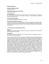
Fig 2. (a) Image of the on-chip sorter described in Fig. 1 (scale bar 500μm). (b) A single worm is shown<br />
trapped by multiple suction channels. A combined white-light <strong>and</strong> fluorescence image is taken by a cooled<br />
CCD camera (Roper Scientific) with 6.5μm pixels <strong>and</strong> a 100ms exposure time through a 0.45 NA 10x<br />
objective lens with (Nikon). mec-4::GFP-expressing touch neurons <strong>and</strong> their processes are clearly visible<br />
(scale bar 10μm). (c) The touch neurons PLML/R <strong>and</strong> ALML/R (L, left; R, right) extend processes along the<br />
anterior <strong>and</strong> posterior half of the worm <strong>and</strong> contribute to mechanosensation in these regions. The cell bodies<br />
are shown as black dots.<br />
The microfluidic chips have flow <strong>and</strong> control layers, <strong>and</strong> are permanently bonded onto glass<br />
substrates to allow optical access. Flow layers are made by casting a room-temperaturevulcanizing<br />
dimethylsiloxane polymer (RTV615, GE Silicones) using a mold consisting of a<br />
patterned layer of positive photoresist (SIPR-7123, Shin-Etsu) on a silicon wafer. Flow-layer<br />
channels are 250-500μm wide, <strong>and</strong> 80-110μm high. The channels are rounded by reflowing the<br />
developed photoresist at 150°C. In the current design, the flow layer is made from a mold with a<br />
single photoresist layer that defines suction channels that are 40μm high <strong>and</strong> 50μm wide after<br />
reflow, which allows capturing of adult worms. In order to capture juvenile worms, a two layer<br />
photoresist mold could be used to make smaller suction channels. Control layers are made by<br />
casting from a mold consisting of a patterned layer of negative photoresist (SU-8 2075,<br />
Microchem) on a silicon wafer. Control channels are 70-80μm high, <strong>and</strong> the membrane that<br />
separates the two layers is 10-20μm thick. PDMS chips cost significantly less than current flowthrough<br />
animal-screening machines, <strong>and</strong> can be easily incorporated into a variety of microscopy<br />
systems.<br />
12-3
Chapter 12. <strong>Bioscreening</strong>, <strong>Biophotonics</strong>, <strong>and</strong> <strong>Micromanipulation</strong><br />
The speed of the sorter depends on the actuation speed of the valves, the concentration of<br />
animals at the input, the flow speed of the worms, <strong>and</strong> the image acquisition <strong>and</strong> processing<br />
times. The technique of immobilizing worms by lowering pressure in a micro-channel is fast<br />
because the actuation speed of the valves is less than 30 milliseconds. Due to the continuous recirculation<br />
at the input, animals can be flowed at high concentration without clogging the chip.<br />
The speed of image acquisition <strong>and</strong> recognition of sub-cellular features is fundamentally limited<br />
by the fluorescence signal-to-noise ratio <strong>and</strong> the complexity of the features being recognized. The<br />
entire worm can be imaged in a single frame using a low magnification, high-NA objective lens.<br />
Cellular <strong>and</strong> sub-cellular features (touch-neuron axons etc.) can be detected by wide-field epifluorescence<br />
where the exposure times are limited by the brightness of the fluorescent markers.<br />
Using a cooled CCD camera, we are able to perform image acquisition at speeds exceeding one<br />
frame every hundred milliseconds when imaging neurons labeled with green fluorescent protein<br />
(GFP). As a result of these features, this design can allow sorting of worms at high speeds.<br />
Large-Scale Time-Lapse Assays with Sub-cellular Resolution<br />
Time-lapse imaging is important for a variety of assays including drug <strong>and</strong> genetic screens.<br />
Currently, high-throughput time-lapse studies on small animals are done in multi-well plates by<br />
automated fluorescence microplate readers (4). Since the animals swim inside the wells, only<br />
average fluorescence is obtained from each well, <strong>and</strong> cellular <strong>and</strong> sub-cellular details cannot be<br />
imaged. Although anesthesia can be used to immobilize the animals, they cannot be kept under<br />
anesthesia for more than a few hours, <strong>and</strong> cannot be anesthetized frequently. Furthermore, the<br />
effect of anesthesia on many biological processes remains uncharacterized. Another limitation of<br />
current multi-well plates is the loss of animals that occurs during media exchange. To address<br />
these problems, we designed the microfluidic-chamber device shown in Fig. 3a for worm<br />
incubation <strong>and</strong> for continuous imaging at sub-cellular resolution. Sorted worms can be delivered<br />
to the chambers by opening valves via multiplexed control lines as described in (14). The<br />
pressure in the control lines is switched on <strong>and</strong> off with external electronically controlled valves<br />
(Numatics TM series actuators). Since the number of control lines required to independently<br />
Valves<br />
A<br />
B<br />
C<br />
D<br />
neuron<br />
Control<br />
lines<br />
Microchambers<br />
address N incubation chambers scales only with log(N) (14), micro-chamber chips based on this<br />
design can be readily scaled for large-scale screening applications. Due to the millimeter scale of<br />
the micro-chambers, hundreds of micro-chambers could be integrated on a single chip. Each<br />
incubation chamber contains posts arranged in an arc. To image animals, a flow is used to push<br />
the animals towards the posts (Fig. 3b-3c). This flow restrains the animals for sub-cellular<br />
imaging. The circular arrangement of the posts reduces the size of the chambers, <strong>and</strong> also<br />
positions the animals in a well-defined geometry to reduce the complexity <strong>and</strong> processing time of<br />
image recognition algorithms. The media in the chambers can be exchanged through the<br />
microfluidic channels for complex screening strategies. Thus, precisely timed exposures to<br />
biochemicals (e.g. drugs/RNAi) can be performed, which is useful both for identifying<br />
mechanisms that rely on the action of more than one compound, <strong>and</strong> for combinatorial assays<br />
involving multiple drug targets. The use of microfluidic technology also reduces the cost of wholeanimal<br />
assays by reducing the required volumes of compounds.<br />
12-4 RLE Progress Report 149
Chapter 12. <strong>Bioscreening</strong>, <strong>Biophotonics</strong>, <strong>and</strong> <strong>Micromanipulation</strong><br />
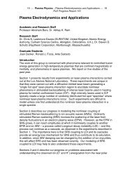
Fig 3. Micro-chamber chip for large-scale screening. (a) Inputs to the chambers are controlled through<br />
multiplexed control lines <strong>and</strong> valves. The same inputs can be used to deliver both worms <strong>and</strong> compounds by<br />
flushing the lines with clean media (scale bar 500μm). (b) A special micro-chamber geometry that consists of<br />
circularly arranged micro-posts can be used to restrain the worms quickly in a well defined geometry without<br />
using anesthetics by applying a gentle flow (scale bar 250μm). (c) High-resolution images can be taken<br />
through the glass substrate of the chip. The GFP-labeled fluorescent touch-neuron image was taken with a<br />
white-light background to show a micro-post (scale bar 25μm). (Images are taken in different devices using<br />
stereo <strong>and</strong> inverted fluorescence microscopes)<br />
Microfluidic Multi-Well-Plate Interface Chip for Compound-Library Delivery <strong>and</strong> Multiplexed<br />
Animal Dispensing<br />
Control Layer<br />
Membrane<br />
Flow Layer<br />
Suction/Dispense<br />
output<br />
control lines<br />
Multi-well Plate<br />
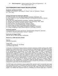
Fig 4. Design for delivery of compounds from st<strong>and</strong>ard multi-well plates to microfluidic devices. A<br />
microfluidic chip loads compounds from 96/384 well plates by aspiration through micro-bore tubing. A<br />
microfluidic multiplexer circuit directs one compound at a time to a serial output, which can be connected to<br />
our micro-chamber screening chip. The micro-chamber chips each have a similar multiplexer circuit [14] to<br />
sort <strong>and</strong> deliver compounds to individual chambers.<br />
Interfacing microfluidics to existing large-scale RNAi <strong>and</strong> drug libraries in st<strong>and</strong>ard multi-well<br />
plates represents a significant challenge. It is impractical to deliver compounds to thous<strong>and</strong>s of<br />
micro-chambers on a single chip through thous<strong>and</strong>s of external fluidic connectors. To address<br />
this problem, we designed the microfluidic interface chip shown in Fig. 4. The device consists of<br />
an array of aspiration tips that can be lowered into the wells of micro-well plates. The chip is<br />
designed to allow minute amounts of library compounds to be collected from the wells by suction,<br />
routed through multiplexed flow lines one at a time, <strong>and</strong> delivered to the single output of the<br />
device. The output of the interface chip could then be connected to our microfluidic-chamber<br />
device for sequential delivery of compounds to each micro-chamber. Combining this multi-wellplate<br />
interface chip with existing robotic multi-well-plate h<strong>and</strong>lers will allow large libraries to be<br />
delivered to microfluidic chips. The same device could also be used to dispense worms into multiwell<br />
plates, simply by running it in reverse.<br />
12-5
Chapter 12. <strong>Bioscreening</strong>, <strong>Biophotonics</strong>, <strong>and</strong> <strong>Micromanipulation</strong><br />
Large-scale Integration <strong>and</strong> Assay Strategies<br />
A<br />
sorter<br />
dispenser<br />
B<br />
sorter<br />
chambers<br />
circulator<br />
…<br />
…<br />
imaging<br />
….<br />
………<br />
multi-well interface<br />
imaging / surgery<br />
multi-well<br />
…<br />
….<br />
………<br />
RNAi/drug library<br />
Fig 5. Possible combinations of our microfluidic technologies for large-scale high-throughput assays. (a)<br />
High-speed phenotype screens (ex: following genetic mutagenesis) can be performed at cellular or subcellular<br />
resolution by cascading the microfluidic sorter with the multi-well dispenser. (b) Large-scale<br />
RNAi/drug screens can be performed by delivering st<strong>and</strong>ard multi-well-plate libraries to the microfluidic<br />
screening chambers via the multi-well interface chips.<br />
Since our sorter <strong>and</strong> micro-chambers are designed to immobilize <strong>and</strong> release animals repeatedly<br />
in less than one hundred milliseconds, the on-chip screening technology that we introduced here<br />
will allow high-throughput whole-animal assays at sub-cellular resolution <strong>and</strong> with time-lapse<br />
imaging. It will be possible to automate a variety of assays by combining our devices in different<br />
configurations: Mutagenesis screens could be performed using our microfluidic sorter in<br />
combination with our microfluidic dispenser to dispense sorted animals at high speeds into the<br />
wells of multi-well plates (Fig. 5a). Large-scale RNAi <strong>and</strong> drug screens with time-lapse imaging<br />
could be performed by combining our sorter, integrated micro-chambers, <strong>and</strong> multi-well-plate<br />
interface chips as shown in Fig. 5b: Although C. elegans is self-fertilizing, <strong>and</strong> has perhaps the<br />
lowest phenotypic variability among multi-cellular organisms (4), variations among assayed<br />
animals are still present, reducing the robustness of current large-scale screens. Sorting<br />
technology can be used to select animals with similar phenotypes (such as fluorescent marker<br />
expression levels) prior to large-scale assays to significantly reduce initial phenotypic variations<br />
(Fig. 5b) (4,15). Our micro-chamber technology could be used with feature-extraction algorithms<br />
to screen thous<strong>and</strong>s of animals on a single chip. An interface to multi-well plates can be used to<br />
deliver large compound libraries to our micro-chambers.<br />
Project 2. Study of neural regeneration in the small-animal model C. elegans using<br />
femtosecond laser nano-surgery<br />
Recently, we demonstrated femtosecond-laser microsurgery in C. elegans as a precise <strong>and</strong><br />
reproducible injury model to study neural degeneration <strong>and</strong> regeneration in vivo (16,17). Since C.<br />
elegans is a genetically amenable organism, we will study factors affecting neural degeneration<br />
<strong>and</strong> regeneration following injury, for the first time on entire genome scale. We have recently built<br />
three femtosecond laser microsurgery setups (Fig. 6). The immobilization technique described in<br />
12-6 RLE Progress Report 149
Chapter 12. <strong>Bioscreening</strong>, <strong>Biophotonics</strong>, <strong>and</strong> <strong>Micromanipulation</strong><br />
Project 1 will allow us to hold the worms still during such precision microsurgical operations, <strong>and</strong><br />
perform time-lapse imaging at sub-cellular resolution following surgery.<br />
CCD<br />
UV<br />
modulator<br />
femtosecond laser<br />
Fig 6. Femtosecond laser microsurgery setup we recently built.<br />
We are also developing automation, pattern recognition <strong>and</strong> image analysis algorithms to<br />
automate <strong>and</strong> quantify our studies. Fig. 7 shows a feature-extracted image of a worm acquired at<br />
cellular resolution after performing femtosecond-laser microsurgery. Time series of such images<br />
could be used to measure growth-cone movement rates, the direction of outgrowth relative to the<br />
original trajectory, <strong>and</strong> the degree of branching for high-throughput, whole-animal studies of<br />
neural degeneration <strong>and</strong> regeneration following injury. Since the immobilized animals are<br />
physiologically active <strong>and</strong> not anesthetized, their neural activity patterns can potentially be<br />
imaged at cellular resolution using genetically encoded optical probes.<br />
ALMR<br />
ALML<br />
AVM<br />
Fig 7. Femtosecond-laser microsurgery of axons. Left panel: Fluorescence images of mec4::GFP-labeled<br />
touch neurons (ALMR, ALML, AVM). Femtosecond-laser microsurgery is performed on the target process<br />
with 100fs, 3nJ pulses at a repetition rate of 80MHz. Right panel: Cell bodies <strong>and</strong> neural processes identified<br />
after edge detection <strong>and</strong> feature extraction (scale bar 5μm). Color coding shows individual cell bodies,<br />
neural processes, <strong>and</strong> the laser cut. Feature extraction was performed by thresholding to first identify<br />
cellular features <strong>and</strong> then, combined with a Canny edge detection algorithm, to identify the outline of neural<br />
processes.<br />
Project 3. Rapid Generation of Complex Neural Circuits <strong>and</strong> Scaffolds<br />
We are currently developing technologies for rapid generation of complex neural circuits <strong>and</strong><br />
scaffolds in 2- <strong>and</strong> 3-dimensions.<br />
References:<br />
1. Kamath, R. S., Fraser, A. G., Dong, Y., Poulin, G., Durbin., R., Gotta, M., Kanapin, A., Le Bot,<br />
N., Moreno, S., Sohrmann, M., Welchman, D. P., Zipperlen, P. & Ahringer, J. (2003) Nature 421,<br />
231-7.<br />
12-7
Chapter 12. <strong>Bioscreening</strong>, <strong>Biophotonics</strong>, <strong>and</strong> <strong>Micromanipulation</strong><br />
2. Simmer, F., Moorman, C., van der Linden, A. M., Kuijk, E., van den Berghe, P. V., Kamath, R.<br />
S., Fraser, A. G., Ahringer, J., & Plasterk, R. H. (2003). PLoS Biol 1, E12.<br />
3. Sieburth, D., Ch'ng, Q., Dybbs, M., Tavazoie, M., Kennedy, S., Wang, D., Dupuy, D., Rual, J.<br />
F., Hill, D. E., Vidal, M., Ruvkun, G., <strong>and</strong> Kaplan, J. M. (2005). Nature 436, 510-517.<br />
4. Kaletta T., Butler L., Bogaert T. (2003) Model Organisms in Drug Discovery (John Wiley &<br />
Sons Ltd., West Sussex, UK).<br />
5. Kaletta, T., & Hengartner, M. O. (2006) Nat Rev Drug Discov 5, 387-398.<br />
6. Segalat, L. (2007) ACS Chem Biol. 2, 231-236.<br />
7. Gray, J. M., Karow, D. S., Lu, H., Chang, A. J., Chang, J. S., Ellis, R. E., Marletta, M. A. &<br />
Bargmann, C. I., (2004) Nature 430, 317-322.<br />
8. Lange, D., Storment, C., Conley, C. & Kovacs, G. (2005) Sensor Actuator B Chem, 107, 904-<br />
914.<br />
9. Heng, X, Erickson, D., Baugh, L. R., Yaqoob, Z., Sternberg, P. W., Psaltis, D. & Yang, C.<br />
(2006) Lab Chip, 6, 1274–1276.<br />
10. Qin, J. & Wheeler, A. R. (2007) Lab Chip, 7, 186-192.<br />
11. Duffy, D. C., McDonald, J. C., Schueller, O. J. A. & Whitesides, G. (1998) Analytical<br />
Chemistry 70, 4974-4984.<br />
12. Unger, M. A., Chou, H-P., Thorsen, T., Scherer, A. & Quake, S. (2000) Science 288, 113-116.<br />
13. Dupuy D. et. al. (2007) Nature Biotechnology 25, 663-668.<br />
14. Melin, J. & Quake, S. (2007) Annu. Rev. Biophys. Biomol. Struct. 36, 213-231.<br />
15. Zhang, J. H., Chung, T. D. & Oldenburg, K. R. (1999) J. Biomol Screen. 4, 67-73.<br />
16. Yanik, M. F., Cinar, H., Cinar, H. N., Chisholm, A., Jin, Y. & Ben-Yakar, A. (2004) Nature 432,<br />
822.<br />
17. Yanik, M. F., Cinar, H., Cinar, H. N., Chisholm, A., Jin, Y. & Ben-Yakar, A. (2006) IEEE<br />
Journal of Quantum Electronics 12, 1283-1291.<br />
12-8 RLE Progress Report 149